Electronically controlled negative resistance based on translinear ...
Electronically controlled negative resistance based on translinear ...
Electronically controlled negative resistance based on translinear ...

Create successful ePaper yourself
Turn your PDF publications into a flip-book with our unique Google optimized e-Paper software.
<str<strong>on</strong>g>Electr<strong>on</strong>ically</str<strong>on</strong>g> <str<strong>on</strong>g>c<strong>on</strong>trolled</str<strong>on</strong>g> <str<strong>on</strong>g>negative</str<strong>on</strong>g> <str<strong>on</strong>g>resistance</str<strong>on</strong>g><br />
<str<strong>on</strong>g>based</str<strong>on</strong>g> <strong>on</strong> <strong>translinear</strong> circuits<br />
Wiwat Kiran<strong>on</strong>, Chariya Loescharataramdee, Naruemol Kiatwarin and Pramote Wardkein<br />
Faculty of Engineering and Research Center for Communicati<strong>on</strong>s and Informati<strong>on</strong> Technology (ReCCIT)<br />
King M<strong>on</strong>gkut’s Institute of Technology Ladkrabang, Bangkok 10520, Thailand<br />
Ph<strong>on</strong>e: (662)3269968 Ext. 109, Fax: (662)7392398, Email: klchariy@kmitl.ac.th<br />
Abstract<br />
This paper presents a novel design of <str<strong>on</strong>g>negative</str<strong>on</strong>g><br />
<str<strong>on</strong>g>resistance</str<strong>on</strong>g> <str<strong>on</strong>g>based</str<strong>on</strong>g> <strong>on</strong> <strong>translinear</strong> circuits. The <str<strong>on</strong>g>resistance</str<strong>on</strong>g> is<br />
electr<strong>on</strong>ically tunable. Hence applicati<strong>on</strong>s of the proposed<br />
<str<strong>on</strong>g>negative</str<strong>on</strong>g> resistor are practically c<strong>on</strong>venient. In additi<strong>on</strong>, the<br />
circuit offers an advantageous feature of compensati<strong>on</strong> for<br />
temperature sensitivity. Simulati<strong>on</strong> results are obtained to<br />
show validity of the theoretical analysis.<br />
V A<br />
I O<br />
I C2<br />
I A<br />
Q 1<br />
Q 2<br />
A<br />
B<br />
Q 3 Q 4<br />
I B<br />
V B<br />
1. Introducti<strong>on</strong><br />
I O<br />
I C4<br />
Negative <str<strong>on</strong>g>resistance</str<strong>on</strong>g> is very useful in various<br />
applicati<strong>on</strong>s in instrumentati<strong>on</strong>, circuit designs and signal<br />
processing. One familiar applicati<strong>on</strong> is to use <str<strong>on</strong>g>negative</str<strong>on</strong>g><br />
<str<strong>on</strong>g>resistance</str<strong>on</strong>g> for impedance matching or improving the quality<br />
factor of an inductor or a res<strong>on</strong>ant circuit [1]. Negative<br />
<str<strong>on</strong>g>resistance</str<strong>on</strong>g> can be used to help set up the oscillatory<br />
c<strong>on</strong>diti<strong>on</strong>s in an oscillator circuit. The use of <str<strong>on</strong>g>negative</str<strong>on</strong>g><br />
<str<strong>on</strong>g>resistance</str<strong>on</strong>g> al<strong>on</strong>g with an integrator helps boost linearity in<br />
integrati<strong>on</strong> process [2].<br />
There are many papers presenting the designs of<br />
<str<strong>on</strong>g>negative</str<strong>on</strong>g> <str<strong>on</strong>g>resistance</str<strong>on</strong>g> <str<strong>on</strong>g>based</str<strong>on</strong>g> <strong>on</strong> variety of techniques. Some<br />
designs directly generate <str<strong>on</strong>g>negative</str<strong>on</strong>g> input impedance [3-5].<br />
Others rely <strong>on</strong> <str<strong>on</strong>g>negative</str<strong>on</strong>g> impedance c<strong>on</strong>verters and <str<strong>on</strong>g>negative</str<strong>on</strong>g><br />
impedance inverters [6]. However, to the best of the authors’<br />
knowledge there has been no attempt made to design<br />
electr<strong>on</strong>ically tunable <str<strong>on</strong>g>negative</str<strong>on</strong>g> <str<strong>on</strong>g>resistance</str<strong>on</strong>g> with a <strong>translinear</strong><br />
implementati<strong>on</strong>. Hence it is the aim of this paper to present<br />
a new development of designing electr<strong>on</strong>ically <str<strong>on</strong>g>c<strong>on</strong>trolled</str<strong>on</strong>g><br />
<str<strong>on</strong>g>negative</str<strong>on</strong>g> <str<strong>on</strong>g>resistance</str<strong>on</strong>g> <str<strong>on</strong>g>based</str<strong>on</strong>g> <strong>on</strong> <strong>translinear</strong> circuits. The design<br />
also has the capability to compensate for changes in<br />
temperature. Not <strong>on</strong>ly that the proposed circuit is suitable<br />
for IC implementati<strong>on</strong> but electr<strong>on</strong>ically tunable feature<br />
makes it appealing for practical applicati<strong>on</strong>s. Simulati<strong>on</strong><br />
results obtained c<strong>on</strong>firm the validity of the theoretical<br />
analysis of the proposed design, that is, <str<strong>on</strong>g>negative</str<strong>on</strong>g> <str<strong>on</strong>g>resistance</str<strong>on</strong>g><br />
with changes in temperature compensated for has been<br />
successfully generated and applied in a res<strong>on</strong>ant circuit in<br />
order to improve its quality factor.<br />
2. Circuit descripti<strong>on</strong><br />
The floating <str<strong>on</strong>g>negative</str<strong>on</strong>g> resistor proposed in the paper<br />
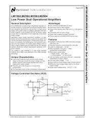
relies <strong>on</strong> the basic <strong>translinear</strong> cell shown in Fig. 1. This is<br />
the same element that Fabre and Member [7] used as a<br />
voltage follower at the fr<strong>on</strong>t end of a current c<strong>on</strong>veyor.<br />
Fig. 1 Basic <strong>translinear</strong> element.<br />
Assume all the standard <strong>translinear</strong> c<strong>on</strong>diti<strong>on</strong>s with respect<br />
to temperature and area juncti<strong>on</strong>s [11], the analysis of the<br />
circuit in Fig. 1 can be described in the following. First, the<br />
base-emitter voltage of Q 2 is found from<br />
V<br />
V<br />
be2<br />
= be1<br />
+ V<br />
A<br />
−V<br />
Using the approximati<strong>on</strong> of the collector current and baseemitter<br />
voltage [8] gives the following collector current of<br />
Q 2<br />
where<br />
I<br />
C2<br />
<br />
= I<br />
=<br />
s<br />
I s e<br />
e<br />
( V<br />
V<br />
V<br />
be1 + A −<br />
T<br />
V<br />
T<br />
B<br />
B<br />
⎛ ⎛ I ⎞<br />
O<br />
VT<br />
VA<br />
VB<br />
I ⎟ ⎞<br />
⎜<br />
ln<br />
⎜<br />
⎟+<br />
−<br />
⎝ ⎝ s ⎠ ⎠<br />
V<br />
V<br />
AB<br />
= VT<br />
(1)<br />
I o e<br />
I s is the reverse saturati<strong>on</strong> of the juncti<strong>on</strong><br />
V T is the thermal voltage<br />
V<br />
AB<br />
= V<br />
A<br />
−V<br />
B<br />
)
In the same manner, the collector current of Q 4 is given by<br />
Therefore,<br />
I<br />
−V<br />
AB<br />
C4 = Ioe<br />
VT<br />
(2)<br />
I<br />
B<br />
= I<br />
Meanwhile, it is not hard to see that<br />
=<br />
I A = 0<br />
− I<br />
C2 C4<br />
⎛V<br />
Io<br />
sinh<br />
⎜<br />
⎝ V<br />
⎞<br />
⎟<br />
⎠<br />
2<br />
AB<br />
(3)<br />
T<br />
The dashed-box c<strong>on</strong>tained in Fig. 2 c<strong>on</strong>sists of a<br />
compound <strong>translinear</strong> cell resulted from c<strong>on</strong>necting two<br />
identical elements of Fig. 1. The current I generated in the<br />
cell is<br />
I<br />
=<br />
⎛V<br />
sinh<br />
⎜<br />
⎝ 2V<br />
⎞<br />
⎟<br />
⎠<br />
2 Io<br />
AB<br />
(4)<br />
T<br />
This current is mirrored to node A and B with<br />
I<br />
AB<br />
= −<br />
⎛V<br />
sinh<br />
⎜<br />
⎝ 2V<br />
⎞<br />
⎟<br />
⎠<br />
2 Io<br />
AB<br />
(5)<br />
T<br />
Expanding the hyperbolic sine term in (5) with the Taylor’s<br />
series. Then with the assumpti<strong>on</strong> that V AB
Since Q 5 , Q 6 , Q 7 and Q 8 compose a current mirror circuit,<br />
I a = I<br />
The current expressed in (9) can then be written as<br />
I<br />
b<br />
=<br />
2I<br />
R<br />
ICID<br />
⎛V<br />
sinh<br />
⎜<br />
⎝V<br />
S<br />
T<br />
⎞<br />
⎟<br />
⎠<br />
(10)<br />
Simulati<strong>on</strong> results with variati<strong>on</strong> of temperature are<br />
shown in Fig. 5. Fig. 5(a) shows the simulati<strong>on</strong> results of<br />
the <str<strong>on</strong>g>negative</str<strong>on</strong>g> <str<strong>on</strong>g>resistance</str<strong>on</strong>g> generator without temperature<br />
compensati<strong>on</strong>. This is the part illustrated in the dashed-box<br />
of Fig. 4. While Fig. 5(b) shows the simulati<strong>on</strong> results of<br />
the complete versi<strong>on</strong> of the proposed <str<strong>on</strong>g>negative</str<strong>on</strong>g> <str<strong>on</strong>g>resistance</str<strong>on</strong>g><br />
with temperature compensati<strong>on</strong>, that is, the whole Fig. 4.<br />
Again if V S
Ω, 0.1 mH, and 1 nF respectively. Varying I R so as to get<br />
various values of the <str<strong>on</strong>g>negative</str<strong>on</strong>g> <str<strong>on</strong>g>resistance</str<strong>on</strong>g>. The frequency<br />
resp<strong>on</strong>se of the loop-current is shown in Fig. 7.<br />
V in<br />
R -R L<br />
Fig. 6 Bandpass filter with <str<strong>on</strong>g>negative</str<strong>on</strong>g> <str<strong>on</strong>g>resistance</str<strong>on</strong>g> to improve<br />
the quality factor.<br />
Fig. 7 Frequency resp<strong>on</strong>se of the loop current.<br />
It is clearly seen that the quality factor of the circuit can be<br />
improved by adjusting the bias current I b such that the total<br />
<str<strong>on</strong>g>resistance</str<strong>on</strong>g> in the circuit is decreasing.<br />
I C<br />
C<br />
the theoretical analysis. The proposed <str<strong>on</strong>g>negative</str<strong>on</strong>g> <str<strong>on</strong>g>resistance</str<strong>on</strong>g><br />
has also been successfully applied to improve the quality<br />
factor of a res<strong>on</strong>ant circuit. In additi<strong>on</strong>, electr<strong>on</strong>ically<br />
<str<strong>on</strong>g>c<strong>on</strong>trolled</str<strong>on</strong>g> positive <str<strong>on</strong>g>resistance</str<strong>on</strong>g> can be easily c<strong>on</strong>structed by<br />
simple modificati<strong>on</strong> to the proposed circuit. Since the<br />
design relies exclusively <strong>on</strong> the use of transistors, it is highly<br />
suitable for IC implementati<strong>on</strong>.<br />
REFERENCES<br />
[1] M. Lapinoja and T. Rahk<strong>on</strong>en, “An Active Tuning and<br />
Impedance Matching Element,” Proc. ISCAS/IEEE,<br />
1998, pp. I-559-I-562.<br />
[2] S. Takagi and N. Fujii, “Novel highly linear MOS<br />
integrator using a <str<strong>on</strong>g>negative</str<strong>on</strong>g> impedance c<strong>on</strong>vertor<br />
(NIC),” Electr<strong>on</strong>. Lett., vol. 30, no. 10, pp. 746-748,<br />
May. 1994.<br />
[3] L. O. Chua, “Bipolar-JFET-MOSFET Negative<br />
Resistance Devices,” IEEE Trans. Circuits Syst., vol.<br />
CAS-32, no. 1, pp. 46-61, Jan 1985.<br />
[4] H. Takagi and G. Kano, “Complementary JFET<br />
Negative <str<strong>on</strong>g>resistance</str<strong>on</strong>g> devices,” IEEE J.Solid-state<br />
circuit, vol. SC-10, pp. 509-515, Dec. 1975.<br />
[5] K. Lehovec and R. Zuleeg, “Negative <str<strong>on</strong>g>resistance</str<strong>on</strong>g> of a<br />
modifided insulated-gate field-effect transistor,”<br />
Proc.IEEE, vol. 62, pp. 1163-1165, Aug. 1974.<br />
[6] C. Toumazou and F. J. Lidgey, “Current-C<strong>on</strong>veyor<br />
Basic and Applicati<strong>on</strong>s,” ISCAS’94, pp. 569-585, 1994.<br />
[7] A. Fabre, O. Saaid, F. Wiest and C. Boucher<strong>on</strong>, “High-<br />
Frequency High-Q BiCMOS current-Mode Bandpass<br />
Filter and Mobile Communicati<strong>on</strong> Applicati<strong>on</strong>,” IEEE<br />
J. Solid-State Circuits, vol. 33, pp. 614-625, Apr. 1998.<br />
[8] A. S. Sedra and K. C. Smith, Microelectr<strong>on</strong>ic Circuits.<br />
Oxford University Press, Inc., 1991.<br />
[9] D. R. Frey, “Log-domain filtering: an approach to<br />
current mode filtering,” IEE Proc. G, vol. 140, pp.<br />
406-416, Dec.1993.<br />
[10] W. Surakamp<strong>on</strong>torn, V. Riewruja, K. Kumwachara and<br />
C. F<strong>on</strong>gsamut, “Temperature compensati<strong>on</strong> of<br />
<strong>translinear</strong> current c<strong>on</strong>veyor and OTA,” Electr<strong>on</strong>. Lett.,<br />
vol. 34, no. 8, pp. 707-709, Apr. 1998.<br />
[11] A. Fabre, “New formulati<strong>on</strong>s to describe <strong>translinear</strong><br />
mixed cells accurately,” IEE Proc.-Circuits Devices<br />
Syst., vol. 141, no.3, Jun 1994.<br />
4. Discussi<strong>on</strong> remarks and C<strong>on</strong>clusi<strong>on</strong>s<br />
This paper presents a new design of floating<br />
<str<strong>on</strong>g>negative</str<strong>on</strong>g> <str<strong>on</strong>g>resistance</str<strong>on</strong>g> <str<strong>on</strong>g>based</str<strong>on</strong>g> <strong>on</strong> <strong>translinear</strong> circuits. The<br />
<str<strong>on</strong>g>negative</str<strong>on</strong>g> <str<strong>on</strong>g>resistance</str<strong>on</strong>g> is successfully generated with linear<br />
performance obtained for the voltage range of + 2V T .<br />
Outside this range, the <str<strong>on</strong>g>negative</str<strong>on</strong>g> <str<strong>on</strong>g>resistance</str<strong>on</strong>g> becomes<br />
n<strong>on</strong>linear. The <str<strong>on</strong>g>resistance</str<strong>on</strong>g> is also electr<strong>on</strong>ically tunable and<br />
temperature dependence compensated for. Simulati<strong>on</strong><br />
results show that the circuit operati<strong>on</strong> is in agreement with