510Sr owner's manual cover 24Oct10 - Diamondback Fitness
510Sr owner's manual cover 24Oct10 - Diamondback Fitness
510Sr owner's manual cover 24Oct10 - Diamondback Fitness

Create successful ePaper yourself
Turn your PDF publications into a flip-book with our unique Google optimized e-Paper software.
14<br />
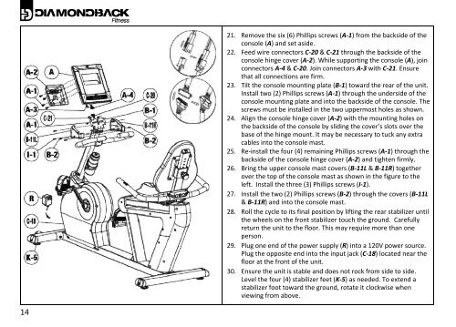
21. Remove the six (6) Phillips screws (A‐1) from the backside of the<br />
console (A) and set aside.<br />
22. Feed wire connectors C‐20 & C‐21 through the backside of the<br />
console hinge <strong>cover</strong> (A‐2). While supporting the console (A), join<br />
connectors A‐4 & C‐20. Join connectors A‐3 with C‐21. Ensure<br />
that all connections are firm.<br />
23. Tilt the console mounting plate (B‐1) toward the rear of the unit.<br />
Install two (2) Phillips screws (A‐1) through the underside of the<br />
console mounting plate and into the backside of the console. The<br />
screws must be installed in the two uppermost holes as shown.<br />
24. Align the console hinge <strong>cover</strong> (A‐2) with the mounting holes on<br />
the backside of the console by sliding the <strong>cover</strong>’s slots over the<br />
base of the hinge mount. It may be necessary to tuck any extra<br />
cables into the console mast.<br />
25. Re‐install the four (4) remaining Phillips screws (A‐1) through the<br />
backside of the console hinge <strong>cover</strong> (A‐2) and tighten firmly.<br />
26. Bring the upper console mast <strong>cover</strong>s (B‐11L & B‐11R) together<br />
over the top of the console mast as shown in the figure to the<br />
left. Install the three (3) Phillips screws (I‐1).<br />
27. Install the two (2) Phillips screws (B‐2) through the <strong>cover</strong>s (B‐11L<br />
& B‐11R) and into the console mast.<br />
28. Roll the cycle to its final position by lifting the rear stabilizer until<br />
the wheels on the front stabilizer touch the ground. Carefully<br />
return the unit to the floor. This may require more than one<br />
person.<br />
29. Plug one end of the power supply (R) into a 120V power source.<br />
Plug the opposite end into the input jack (C‐18) located near the<br />
floor at the front of the unit.<br />
30. Ensure the unit is stable and does not rock from side to side.<br />
Level the four (4) stabilizer feet (K‐5) as needed. To extend a<br />
stabilizer foot toward the ground, rotate it clockwise when<br />
viewing from above.