Instruction Sheet - Laser alignment tool for Flo-Dar - Hachflow
Instruction Sheet - Laser alignment tool for Flo-Dar - Hachflow
Instruction Sheet - Laser alignment tool for Flo-Dar - Hachflow

Create successful ePaper yourself
Turn your PDF publications into a flip-book with our unique Google optimized e-Paper software.
<strong>Instruction</strong> <strong>Sheet</strong><br />
DOC306.53.00817<br />
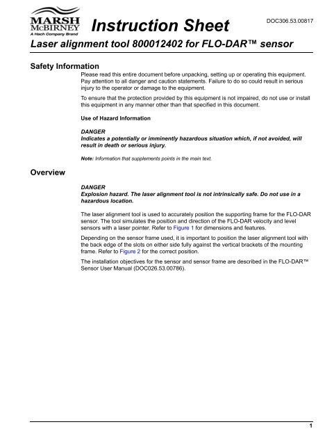
<strong>Laser</strong> <strong>alignment</strong> <strong>tool</strong> 800012402 <strong>for</strong> FLO-DAR sensor<br />
Safety In<strong>for</strong>mation<br />
Please read this entire document be<strong>for</strong>e unpacking, setting up or operating this equipment.<br />
Pay attention to all danger and caution statements. Failure to do so could result in serious<br />
injury to the operator or damage to the equipment.<br />
Overview<br />
To ensure that the protection provided by this equipment is not impaired, do not use or install<br />
this equipment in any manner other than that specified in this document.<br />
Use of Hazard In<strong>for</strong>mation<br />
DANGER<br />
Indicates a potentially or imminently hazardous situation which, if not avoided, will<br />
result in death or serious injury.<br />
Note: In<strong>for</strong>mation that supplements points in the main text.<br />
DANGER<br />
Explosion hazard. The laser <strong>alignment</strong> <strong>tool</strong> is not intrinsically safe. Do not use in a<br />
hazardous location.<br />
The laser <strong>alignment</strong> <strong>tool</strong> is used to accurately position the supporting frame <strong>for</strong> the FLO-DAR<br />
sensor. The <strong>tool</strong> simulates the position and direction of the FLO-DAR velocity and level<br />
sensors with a laser pointer. Refer to Figure 1 <strong>for</strong> dimensions and features.<br />
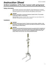
Depending on the sensor frame used, it is important to position the laser <strong>alignment</strong> <strong>tool</strong> with<br />
the back edge of the slots on either side fully against the vertical brackets of the mounting<br />
frame. Refer to Figure 2 <strong>for</strong> the correct position.<br />
The installation objectives <strong>for</strong> the sensor and sensor frame are described in the FLO-DAR<br />
Sensor User Manual (DOC026.53.00786).<br />
1
<strong>Laser</strong> <strong>alignment</strong> <strong>tool</strong> 800012402 <strong>for</strong> FLO-DAR sensor<br />
Figure 1 <strong>Laser</strong> <strong>alignment</strong> <strong>tool</strong> dimensions and features<br />
1 Bubble level 3 <strong>Laser</strong> pointer<br />
2 Level position slot <strong>for</strong> laser pointer 4 Velocity position slot <strong>for</strong> laser pointer<br />
Figure 2 <strong>Laser</strong> <strong>alignment</strong> <strong>tool</strong> on frame<br />
1 Frame <strong>for</strong> <strong>Flo</strong>-<strong>Dar</strong> sensor with extended range depth sensor<br />
2 Standard frame<br />
2
<strong>Laser</strong> <strong>alignment</strong> <strong>tool</strong> 800012402 <strong>for</strong> FLO-DAR sensor<br />
Velocity sensor frame adjustment<br />
1. Snap the laser pointer in the velocity position (see Figure 1) of the <strong>alignment</strong> <strong>tool</strong>.<br />
Make sure the laser pointer is fully seated in the slot.<br />
2. Position the <strong>alignment</strong> <strong>tool</strong> on the frame as shown in Figure 2.<br />
3. With the frame clamp bolts loosened enough to allow adjustment but tight enough to<br />
hold in position, level the frame with the bubble level.<br />
Note: If the pipe is not level and has a slope of 2 degrees or more, align the sensor to be parallel<br />
with the surface of the water.<br />
4. Turn the laser pointer on. Adjust the frame so that the laser beam just passes below<br />
the crown of the pipe as shown in Figure 3.<br />
Note: A sheet of paper can be applied across the upper face of the pipe as a reflective surface. This<br />
is useful to show the elevation of the laser beam below the pipe crown.<br />
1 Replace 2-¼ in. spacer with cut lengths of 12 in. spacer<br />
as necessary<br />
Figure 3 Velocity sensor adjustments<br />
2 <strong>Laser</strong> pointer in the velocity sensor position 4 Paper<br />
3 For <strong>Flo</strong>-<strong>Dar</strong> sensors without the SVS option, adjust this<br />
dimension as necessary<br />
3
<strong>Laser</strong> <strong>alignment</strong> <strong>tool</strong> 800012402 <strong>for</strong> FLO-DAR sensor<br />
Level sensor frame adjustment<br />
Note: The purpose of this adjustment is to center the level sensor over the flow. This adjustment also<br />
affects the velocity position.<br />
1. Snap the laser pointer in the level position (see Figure 1) of the <strong>alignment</strong> <strong>tool</strong>. Make sure<br />
the laser pointer is fully seated in the slot.<br />
2. Position the <strong>alignment</strong> <strong>tool</strong> on the frame as shown in Figure 2.<br />
3. Turn the laser pointer on. Adjust the frame so that the laser beam is in the center of the<br />
flow (pipe). Use a tape measure to find the center. Side to side movement and rotation<br />
along the long axis of the frame will center the beam as shown in Figure 4.<br />
4. Examine the velocity sensor position again and adjust if necessary.<br />
5. When the bubble level is centered and the velocity and level sensor adjustments are<br />
complete, tighten all bolts.<br />
Note: If the pipe is not level and has a slope of 2 degrees or more, align the sensor to be parallel with the<br />
surface of the water.<br />
Figure 4 Level sensor adjustments<br />
1 <strong>Laser</strong> pointer in the level sensor position<br />
© Hach Company, 2007. All rights reserved. Printed in the U.S.A. Edition 1, December 2007