FL900 Series Manual - English EU - Hachflow
FL900 Series Manual - English EU - Hachflow
FL900 Series Manual - English EU - Hachflow

You also want an ePaper? Increase the reach of your titles
YUMPU automatically turns print PDFs into web optimized ePapers that Google loves.
DOC026.52.80015<br />
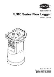
<strong>FL900</strong> <strong>Series</strong> Flow Logger<br />
08/2013, Edition 6<br />
User <strong>Manual</strong>
Table of Contents<br />
Specifications..............................................................................................................3<br />
General information..................................................................................................5<br />
Safety information........................................................................................................6<br />
Use of hazard information....................................................................................6<br />
Precautionary labels.............................................................................................6<br />
Confined space precautions.................................................................................7<br />
Certification..................................................................................................................7<br />
Wi-Fi devices...............................................................................................................8<br />
Country-specific approval for Wi-Fi devices.........................................................8<br />
Certification...........................................................................................................9<br />
Product overview.........................................................................................................9<br />
Product components .................................................................................................11<br />
Apply power to the Logger .................................................................................12<br />
Install the batteries.....................................................................................................12<br />
Attach an external power supply (optional)................................................................14<br />
System startup..........................................................................................................15<br />
Install the Flo-Ware <strong>FL900</strong> Driver..............................................................................15<br />
Attach the logger to the computer..............................................................................15<br />
Attach a sensor or external devices to the logger......................................................16<br />
Attach an external module.........................................................................................17<br />
Attach a sampler........................................................................................................17<br />
User interface ...........................................................................................................18<br />
Program a unit equipped with a modem........................................................18<br />
Set up the wireless account.......................................................................................18<br />
Install a SIM card (GPRS only)........................................................................... 19<br />
Set up a GPRS modem-based account.............................................................21<br />
Attach an antenna (wireless option)...................................................................21<br />
Add the logger to the FSDATA Server...............................................................21<br />
Configure Flo-Ware for remote communication.................................................. 22<br />
Verify the telemetry (wireless option).................................................................23<br />
Verify the telemetry with Flo-Ware.....................................................................24<br />
Troubleshooting telemetry..................................................................................24<br />
Use the mobile SMS option................................................................................24<br />
Modbus communication.......................................................................................25<br />
Basic setup.................................................................................................................25<br />
Make a basic logger program....................................................................................25<br />
Calibrate the sensor with the Cal Wizard...................................................................26<br />
Site installation ........................................................................................................27<br />
Hang from a cable.....................................................................................................27<br />
Install on a wall bracket.............................................................................................27<br />
Maintenance ..............................................................................................................27<br />
Clean the instrument..................................................................................................28<br />
Replace the batteries.................................................................................................28<br />
Replace the desiccant...............................................................................................28<br />
1
Table of Contents<br />
Troubleshooting ......................................................................................................28<br />
Communication failure...............................................................................................29<br />
Replacement parts and accessories...............................................................29<br />
2
Specifications<br />
Specifications are subject to change without notice.<br />
Specification<br />
Dimensions (W x D x H)<br />
Enclosure<br />
Environmental rating<br />
Weight (model <strong>FL900</strong>)<br />
Operating temperature<br />
Storage temperature<br />
Power requirements<br />
Battery life<br />
Details<br />
25.4 x 22 x 40 cm (10.0 x 8.7 x 16.0 in.)<br />
PC/ABS structural foam<br />
NEMA 6P/IP68 (24 hours at 1.8 m (6 ft) submersion)<br />
4.5 kg (10 lb) with no batteries, 6.3 kg (14 lb) with 2 batteries and 8.2 kg (18 lb)<br />
with 4 batteries<br />
–18 to 60 ºC (0 to 140 ºF) at 95% RH<br />
–40 to 60 ºC (–40 to 140 ºF)<br />
8 to 18 VDC from batteries or external power source, 2.5 W max<br />
Varies with sensor type, logging intervals, telemetry and environment.<br />
For a 15 minute logging interval, with no modem, four 6 V lantern batteries at<br />
room temperature:<br />
• Flo-tote 3 sensor 306 days<br />
• Area Velocity sensor with AV9000 Analyzer 296 days<br />
• Flo-Dar sensor 185 days<br />
• Ultrasonic sensor 456 days<br />
Note: For longer deployments use with Long Life Battery, PN 8542900.<br />
Installation category<br />
Protection class<br />
I<br />
III<br />
Pollution degree 1<br />
Sensor ports<br />
1, 2 or 4 ports<br />
Primary devices Contains algorithms to support the primary devices that are shown in Table 1.<br />
Connectors<br />
Datalog channels<br />
Alarms<br />
Stainless steel connectors<br />
16 maximum<br />
Maximum of 16 channel alarms with high/high, high, low, low/low options.<br />
System alarms include low battery, low RTC battery, low slate memory, slate<br />
memory full, sensor time out, sensor ID.<br />
Alarm actions Start the sampler, change the log interval, change the call interval, send an e-<br />
mail or a text message (SMS) from logger or server.<br />
Logging intervals<br />
1, 2, 3, 4, 5, 6, 10, 12, 15, 20, 30 or 60 minutes<br />
Primary and secondary intervals for dynamic logging<br />
Data storage<br />
Event log: 1000 events maximum in non-volatile flash memory<br />
Sample history: 2000 sample events maximum in non-volatile flash memory<br />
Datalog: 325,000 data points; 1128 days for 3 channels at 15-minute log<br />
intervals<br />
PC communication<br />
USB<br />
RS232 (Baud rates: 9600, 19200, 38400, 57600, 115200)<br />
Remote communication<br />
(optional)<br />
Wireless modem; CDMA2000 1xRTT or GPRS<br />
<strong>English</strong> 3
Specification<br />
Protocols<br />
Details<br />
Modbus RTU<br />
Mobile-Terminated SMS<br />
Mobile-Originated SMS<br />
Timebase accuracy<br />
Supported sensors<br />
Sampler interface<br />
Certifications<br />
±0.002%, synchronized every 24 hours with server software and modem<br />
Flo-Dar, Flo-Dar with SVS, Flo-Tote, Rain Gauge, Ultrasonic, Submerged Area<br />
Velocity 1 , Sigma 950 1<br />
Compatible with Sigma 900 Standard, Sigma 900 Max and Hach SD900 to<br />
support set point sampling, flow-pacing and sample history logging<br />
Logger: CE<br />
Optional AC power supply: UL/CSA standards (cETLus)/CE<br />
Modems: FCC, NB, IC, others may be available—contact the manufacturer for<br />
more information.<br />
Warranty<br />
1 year<br />
1 This device attaches through an external module. Refer to External devices on page 30.<br />
Primary devices Type Details<br />
Table 1 Primary devices supported<br />
Weir V-notch 22.5–120 ° notch<br />
Contracted<br />
rectangular<br />
Non-contracted<br />
rectangular<br />
Cipolletti<br />
Compound V-notch<br />
ThelMar<br />
22.5–120 ° notch, 0–61 cm (0–24 in.) notch height, contracted and<br />
non-contracted<br />
6, 8, 10, 12 and 15 in.<br />
Nozzles Kennison 6, 8, 10, 12, 16, 20, 24, 30 or 36 in. diameter, half and not half<br />
California Pipe<br />
91 cm (36 in.) diameter and less<br />
4 <strong>English</strong>
Primary devices Type Details<br />
Table 1 Primary devices supported (continued)<br />
Flumes Parshall 1, 2, 3, 6, 9, 12, 18, 24, 30, 36, 48, 60, 72, 84, 96, 108, 120, 144,<br />
180, 240, 300, 360, 480 and 600 in. throat width<br />
Palmer-Bowlus<br />
Leopold-Lagco<br />
HS<br />
H<br />
HL<br />
Trapezoidal<br />
Cutthroat<br />
RBC<br />
4, 6, 8, 10, 12, 15, 18, 21, 24, 27, 30, 36, 42, 48, 60 and 72 in.<br />
flume<br />
4, 6, 8, 10, 12, 15, 18, 20, 21, 24, 27, 30, 36, 42, 48, 54, 60, 66 and<br />
72 in. pipe diameter<br />
0.4, 0.6, 0.8 and 1.0 ft flume<br />
0.5, 0.75, 1.0, 1.5, 2, 2.5, 3 and 4.5 ft flume<br />
3 ft and 4 ft flume<br />
12 in. 45 ° SRCRC, 2 in. 45 ° WSC, 8 in. 60 ° V, small 60° V, large<br />
60 ° V and extra large 60 ° V<br />
1, 2, 3, 4, 6, 8, 12, 16, 24, 48 and 72 in. throat width, 8, 36, 54 and<br />
108 in. length of rectangular cutthroat<br />
50, 75, 100, 150 and 200 mm flume<br />
Montana 1, 2, 3, 6, 9, 12, 18, 24, 30, 36, 48, 60, 72, 84, 96, 108, 120, 144,<br />
180, 240, 300, 360, 480 and 600 in. throat width<br />
British Rectangular 1, 2, 3, 6, 9, 12, 18, 24, 30, 36, 48, 60, 72, 84, 96, 108, 120, 144,<br />
180, 240, 300, 360, 480 and 600 in. throat width<br />
San Dimas<br />
More than 0 in. flume<br />
Manning equations Circular More than 0 in. diameter, 0–1.0 slope, 0.0010–0.75 roughness<br />
coefficient<br />
Rectangular<br />
Trapezoidal<br />
U-shape<br />
More than 0 in. width, more than 0 in. height of the channel,<br />
0–1.0 slope, 0.0010–0.75 roughness coefficient<br />
More than 0 in. bottom width, more than 0 in. height of the<br />
trapezoidal part of the channel, more than 0 in. top width,<br />
0–1.0 slope, 0.0010–0.75 roughness coefficient<br />
More than 0 in. diameter, more than diameter/2 in. channel height,<br />
0–1.0 slope, 0.0010–0.75 roughness coefficient<br />
Area velocity<br />
Circular<br />
Rectangular<br />
Trapezoidal<br />
U-shape<br />
Level area table<br />
60-point table<br />
Tables Head flow 60-point table<br />
General information<br />
In no event will the manufacturer be liable for direct, indirect, special, incidental or consequential<br />
damages resulting from any defect or omission in this manual. The manufacturer reserves the right to<br />
make changes in this manual and the products it describes at any time, without notice or obligation.<br />
Revised editions are found on the manufacturer’s website.<br />
<strong>English</strong> 5
Safety information<br />
N O T I C E<br />
The manufacturer is not responsible for any damages due to misapplication or misuse of this product including,<br />
without limitation, direct, incidental and consequential damages, and disclaims such damages to the full extent<br />
permitted under applicable law. The user is solely responsible to identify critical application risks and install<br />
appropriate mechanisms to protect processes during a possible equipment malfunction.<br />
Please read this entire manual before unpacking, setting up or operating this equipment. Pay<br />
attention to all danger and caution statements. Failure to do so could result in serious injury to the<br />
operator or damage to the equipment.<br />
Make sure that the protection provided by this equipment is not impaired. Do not use or install this<br />
equipment in any manner other than that specified in this manual.<br />
Use of hazard information<br />
D A N G E R<br />
Indicates a potentially or imminently hazardous situation which, if not avoided, will result in death or serious injury.<br />
W A R N I N G<br />
Indicates a potentially or imminently hazardous situation which, if not avoided, could result in death or serious<br />
injury.<br />
C A U T I O N<br />
Indicates a potentially hazardous situation that may result in minor or moderate injury.<br />
N O T I C E<br />
Indicates a situation which, if not avoided, may cause damage to the instrument. Information that requires special<br />
emphasis.<br />
Precautionary labels<br />
Read all labels and tags attached to the instrument. Personal injury or damage to the instrument<br />
could occur if not observed. A symbol on the instrument is referenced in the manual with a<br />
precautionary statement.<br />
This is the safety alert symbol. Obey all safety messages that follow this symbol to avoid potential<br />
injury. If on the instrument, refer to the instruction manual for operation or safety information.<br />
This symbol indicates that a risk of electrical shock and/or electrocution exists.<br />
This symbol indicates the presence of devices sensitive to Electro-static Discharge (ESD) and<br />
indicates that care must be taken to prevent damage with the equipment.<br />
This symbol indicates radio waves.<br />
Electrical equipment marked with this symbol may not be disposed of in European public disposal<br />
systems after 12 August of 2005. In conformity with European local and national regulations (<strong>EU</strong><br />
Directive 2002/96/EC), European electrical equipment users must now return old or end-of-life<br />
equipment to the Producer for disposal at no charge to the user.<br />
Note: For return for recycling, please contact the equipment producer or supplier for instructions on how to return endof-life<br />
equipment, producer-supplied electrical accessories, and all auxiliary items for proper disposal.<br />
6 <strong>English</strong>
Confined space precautions<br />
D A N G E R<br />
Explosion hazard. Training in pre-entry testing, ventilation, entry procedures, evacuation/rescue<br />
procedures and safety work practices is necessary before entering confined spaces.<br />
The information that follows is supplied to help users understand the dangers and risks that are<br />
associated with entry into confined spaces.<br />
On April 15, 1993, OSHA's final ruling on CFR 1910.146, Permit Required Confined Spaces, became<br />
law. This standard directly affects more than 250,000 industrial sites in the United States and was<br />
created to protect the health and safety of workers in confined spaces.<br />
Definition of a confined space:<br />
A confined space is any location or enclosure that has (or has the immediate potential for) one or<br />
more of the following conditions:<br />
• An atmosphere with an oxygen concentration that is less than 19.5% or more than 23.5% and/or a<br />
hydrogen sulfide (H 2 S) concentration that is more than 10 ppm.<br />
• An atmosphere that can be flammable or explosive due to gases, vapors, mists, dusts or fibers.<br />
• Toxic materials which upon contact or inhalation can cause injury, impairment of health or death.<br />
Confined spaces are not designed for human occupancy. Confined spaces have a restricted entry<br />
and contain known or potential hazards. Examples of confined spaces include manholes, stacks,<br />
pipes, vats, switch vaults and other similar locations.<br />
Standard safety procedures must always be obeyed before entry into confined spaces and/or<br />
locations where hazardous gases, vapors, mists, dusts or fibers can be present. Before entry into a<br />
confined space, find and read all procedures that are related to confined space entry.<br />
Certification<br />
Canadian Radio Interference-Causing Equipment Regulation, IECS-003, Class A:<br />
Supporting test records reside with the manufacturer.<br />
This Class A digital apparatus meets all requirements of the Canadian Interference-Causing<br />
Equipment Regulations.<br />
Cet appareil numérique de classe A répond à toutes les exigences de la réglementation canadienne<br />
sur les équipements provoquant des interférences.<br />
FCC Part 15, Class "A" Limits<br />
Supporting test records reside with the manufacturer. The device complies with Part 15 of the FCC<br />
Rules. Operation is subject to the following conditions:<br />
1. The equipment may not cause harmful interference.<br />
2. The equipment must accept any interference received, including interference that may cause<br />
undesired operation.<br />
Changes or modifications to this equipment not expressly approved by the party responsible for<br />
compliance could void the user's authority to operate the equipment. This equipment has been tested<br />
and found to comply with the limits for a Class A digital device, pursuant to Part 15 of the FCC rules.<br />
These limits are designed to provide reasonable protection against harmful interference when the<br />
equipment is operated in a commercial environment. This equipment generates, uses and can<br />
radiate radio frequency energy and, if not installed and used in accordance with the instruction<br />
manual, may cause harmful interference to radio communications. Operation of this equipment in a<br />
residential area is likely to cause harmful interference, in which case the user will be required to<br />
correct the interference at their expense. The following techniques can be used to reduce<br />
interference problems:<br />
<strong>English</strong> 7
1. Disconnect the equipment from its power source to verify that it is or is not the source of the<br />
interference.<br />
2. If the equipment is connected to the same outlet as the device experiencing interference, connect<br />
the equipment to a different outlet.<br />
3. Move the equipment away from the device receiving the interference.<br />
4. Reposition the receiving antenna for the device receiving the interference.<br />
5. Try combinations of the above.<br />
Wi-Fi devices<br />
N O T I C E<br />
Network and access point security is the responsibility of the customer that uses the wireless instrument. The<br />
manufacturer will not be liable for any indirect, special, incidental or consequential damages caused by a breach<br />
in network security.<br />
Country-specific approval for Wi-Fi devices<br />
C A U T I O N<br />
Electromagnetic radiation hazard. Make sure that the antenna is kept at a minimum distance of 20 cm<br />
(7.9 in.) from all personnel in normal use. The antenna cannot be co-located or operated in conjunction<br />
with any other antenna or transmitters.<br />
Products with the wireless option contain a modular RF Wi-Fi device and are approved as a modular<br />
device under a TCB Grant of Authorization.<br />
Modem MTSMC-C1-GP (CDMA):<br />
• United States FCC ID: AU792U09G17825<br />
• Canada IC ID: 125A-034<br />
Modem MTSMC-G2-IP (GSM):<br />
• United States FCC: AU792U09D24824<br />
• Canada IC ID: 125A-0033<br />
Country ISO31662 letter code Country ISO31662 letter code<br />
Austria AT Poland PL<br />
Belgium BA Portugal PT<br />
Denmark DK Spain ES<br />
Finland FI Sweden SE<br />
France FR United Kingdom GB<br />
Germany DE Iceland IS<br />
Greece GR Norway NO<br />
Hungary HU Switzerland CH<br />
Ireland IE Turkey TR<br />
Italy IT Netherlands NL<br />
Mexico MX — —<br />
Regulatory RF device approvals<br />
Modem MTSMC-C1-GP (CDMA):<br />
• FCC: Approved as a Modular Device under a TCB Grant of Authorization. FCC ID:<br />
AU792U09G17825<br />
8 <strong>English</strong>
• IC: Approved as a Modular Device under Certificat D'Acceptabilite' Technique C-REL ID:<br />
125A-034<br />
Modem MTSMC-G2-IP (GSM):<br />
• FCC: Approved as a Modular Device under a TCB Grant of Authorization. FCC ID:<br />
AU792U09D24824<br />
• IC: Approved as a Modular Device under Certificat D'Acceptabilite' Technique C-REL ID:<br />
125A-0033<br />
Opinion: Compliant under the R&TTE Directive 1999/5/EC to the essentials requirements of Article<br />
3.2 according to the assessment procedures in Article 10(5) and Annex IV for (class-2 equipment)<br />
and marked as CE1177.<br />
Certification<br />
The device complies with Part 15 of the FCC Rules and Industry Canada license-exempt RSS<br />
standard(s). Operation is subject to the following conditions:<br />
1. The equipment may not cause harmful interference.<br />
2. The equipment must accept any interference received, including interference that may cause<br />
undesired operation.<br />
Changes or modifications to this wireless communication equipment not expressly approved by the<br />
party responsible for compliance could void the user's authority to operate the equipment. Any<br />
change to the equipment will void the Industry Canada certification and FCC grant.<br />
Product overview<br />
The <strong>FL900</strong> series flow loggers are used in open-channel flow monitoring studies such as inflow &<br />
infiltration (I&I), combined sewer overflow (CSO), capacity and planning and storm water runoff<br />
monitoring.<br />
Data is collected from attached sensors and logged for future retrieval. The sensors can be added or<br />
changed in the field. Depending on the model, up to four sensors can be connected. The data can be<br />
retrieved directly through a USB or RS232 cable or remotely through a wireless network with Flo-<br />
Ware desktop software and FSDATA server software. Refer to Figure 1. The <strong>FL900</strong> <strong>Series</strong> loggers<br />
can also connect to an external power source, rain gauge or be used to pace a Sigma sampler.<br />
The wireless option and the number of available connectors varies with the model of the logger.<br />
Refer to Figure 2 and Figure 3.<br />
<strong>English</strong> 9
Figure 1 System overview with wireless option<br />
Figure 2 Connectors—side 1<br />
1 Sensor (all models) 3 Computer—USB or RS232 cable (all models)<br />
2 Sensor (FL902, FL904 only) 4 Auxiliary—external power or sampler (all but <strong>FL900</strong>)<br />
10 <strong>English</strong>
Figure 3 Connectors—side 2<br />
1 Sensor (FL904 only) 3 Antenna option (all but <strong>FL900</strong>)<br />
2 Sensor (FL904 only) 4 Rain gauge (all but <strong>FL900</strong>)<br />
Product components<br />
Make sure that all components have been received. Refer to Figure 4. If any items are missing or<br />
damaged, contact the manufacturer or a sales representative immediately.<br />
Figure 4 <strong>FL900</strong> series logger components<br />
1 Logger 3 D-ring with threaded lock<br />
2 Cable, suspension 4 Batteries, 6 V alkaline (4x)<br />
<strong>English</strong> 11
Apply power to the Logger<br />
Install the batteries<br />
W A R N I N G<br />
Explosion hazard. Incorrect battery installation can cause the release of explosive gases. Be sure that<br />
the batteries are of the same approved chemical type and are inserted in the correct orientation. Do not<br />
mix new and used batteries.<br />
W A R N I N G<br />
Fire hazard. Battery substitution is not permitted. Use only alkaline batteries.<br />
N O T I C E<br />
Do not over-tighten the cover. Tighten until the cover just touches the O-ring, then tighten one-quarter to one-half<br />
turn maximum from O-ring contact. Keep the O-ring lubricated with silicone grease.<br />
The instrument can use two or four 6 V batteries for power. Use two batteries for short-term use or<br />
four batteries for long-term use (for battery life, refer to Specifications on page 3). When only two<br />
batteries are used, put both batteries on the same side of the compartment (A-A or B-B). Refer to the<br />
illustrated steps that follow.<br />
Changes in temperature and pressure can cause the battery compartment cover to be difficult to<br />
remove by hand. If this occurs, a tool can be used to remove the cover (Figure 5).<br />
Figure 5 Battery cover removal<br />
12 <strong>English</strong>
1 2<br />
3<br />
<strong>English</strong> 13
Attach an external power supply (optional)<br />
W A R N I N G<br />
Potential explosion hazard. The instrument is not approved for use in hazardous locations.<br />
The instrument can be powered by an external long-life battery, an SD900 power supply or other<br />
source that can supply power in the specified range (refer to Specifications on page 3 and<br />
Replacement parts and accessories on page 29). If the logger has both external power and internal<br />
batteries, the internal batteries are used as an auxiliary power supply. When the external power falls<br />
below approximately 9 V, the internal batteries supply power until the voltage from the external<br />
source is above 9 V.<br />
1. Install the external power source in a safe location near the logger. Be sure to obey all safety<br />
precautions for the power supply.<br />
2. Attach the cable from the power source to the AUX connector on the logger (Figure 6).<br />
3. Apply power to the power source, if applicable.<br />
Figure 6 External power options<br />
1 2-conductor power cable (Figure 7) 3 SD900 power supply<br />
2 Power adapter cable 4 Long-life battery<br />
14 <strong>English</strong>
Figure 7 2-conductor power cable wiring<br />
1 Power—#16 AWG red 2 Common—#16 AWG black<br />
System startup<br />
Install the Flo-Ware <strong>FL900</strong> Driver<br />
Note: During driver installation this message will appear: "The following device has not passed the Windows Logo<br />
testing to verify its compatibility with Windows. Continuing your installation of this software may impair the correct<br />
operation of your system either immediately or in the future. Microsoft strongly recommends that you stop this<br />
installation now and contact the hardware vendor for software that has passed Windows Logo testing." Hach<br />
engineers have fully tested this product and determined that it is compatible with Windows. Press the "Continue<br />
anyway" button to finish the installation.<br />
Pre-requisite: Before the <strong>FL900</strong> logger is attached to a computer, make sure that Flo-Ware is<br />
installed on the computer.<br />
The <strong>FL900</strong> <strong>Series</strong> Driver must be installed on the PC to communicate with the logger. To find driver<br />
updates, refer to the Flo-Ware installation section.<br />
1. Find the link for the <strong>FL900</strong> <strong>Series</strong> Driver on the Flo-Ware CD or from the website<br />
http://www.hachflow.com/p_soft_floware_down.html<br />
2. Click on the link and run the application. The install wizard starts.<br />
3. Follow the on-screen instructions to install the driver. Use the recommended settings.<br />
Attach the logger to the computer<br />
Pre-requisite: Make sure that the <strong>FL900</strong> driver is installed on the computer.<br />
Connect only one logger to the computer.<br />
1. Attach the logger to the computer (Figure 8).<br />
2. When a USB cable is attached for the first time, the Found New Hardware wizard opens. Run the<br />
new hardware wizard to install the USB driver for the logger. When finished, the message “Your<br />
new hardware is installed and ready to use” is shown. In the event the wizard does not run or the<br />
install fails, contact Hach Flow Tech Support to assist with trouble shooting your specific<br />
operating system.<br />
<strong>English</strong> 15
Figure 8 Attach the logger to a computer<br />
Attach a sensor or external devices to the logger<br />
Pre-requisite: Make sure that the connection status is offline.<br />
W A R N I N G<br />
Sensor Hazardous Locations and RF Exposure Hazards. Some sensors have RF radiation exposure hazards and<br />
are used in explosive atmospheres. See sensor manual warnings and instructions before connecting a sensor to<br />
the logger.<br />
The number of sensors that can attach to the logger varies with the model of the logger. Some<br />
sensors must attach to an external module that is used as an interface between the sensor and the<br />
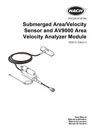
logger. Figure 10 shows the AV9000 Area Velocity Analyzer module on the side of the logger and the<br />
connection to a submerged area/velocity sensor.<br />
1. If the sensor cable has connectors on both ends, attach the cable to the sensor first.<br />
2. Attach the sensor (or module) to any SENSOR port on the logger (Figure 9 or Figure 10). Tighten<br />
the connector by hand.<br />
Note: For rain gauges, attach the sensor to the RAIN connector.<br />
3. If the sensor uses an external module, attach the module to the logger, then attach the sensor to<br />
the module (Figure 10).<br />
4. If the sensor cable has a desiccant hub, align the desiccant hub vertically and make sure that the<br />
air port points down (Figure 9).<br />
16 <strong>English</strong>
Figure 9 Attach a sensor to the logger<br />
Figure 10 Attach a sensor to an external module<br />
Attach an external module<br />
An external module must be used as an interface between some sensor types and the logger. The<br />
external module is mounted on the side of the logger (Figure 10 on page 17). Refer to the<br />
documentation that is supplied with the module for mounting instructions.<br />
Attach a sampler<br />
The logger can attach to a Sigma 900 Standard, Sigma 900 Max or Hach SD900 sampler for flowpaced<br />
and set point sampling. The sampler also supplies power to the logger and to attached<br />
<strong>English</strong> 17
sensors. Connect the auxiliary cable to the AUX port on the logger and to the auxiliary port on the<br />
sampler. To make a sampler program, refer to the documentation that is supplied with the sampler.<br />
User interface<br />
The indicators on the user interface show the status of the instrument and the modem. Refer to<br />
Figure 11 and Table 2.<br />
Figure 11 User interface<br />
1 Instrument without modem 2 Instrument with modem<br />
Indicator LED color Description<br />
Table 2 LED status indicators<br />
Green<br />
Red<br />
Green<br />
Red<br />
Flashes every 3 seconds during normal operation. Flashes every<br />
15 seconds during sleep mode.<br />
Flashes when an attached sensor does not agree with the logger<br />
program, an expected sensor is not found or the sensor operation has<br />
failed.<br />
Stays green during a call to the server.<br />
Flashes red if the call to the server failed.<br />
Program a unit equipped with a modem<br />
C A U T I O N<br />
Electromagnetic radiation hazard. Make sure that the antenna is kept at a minimum distance of 20 cm<br />
(7.9 in.) from all personnel in normal use. The antenna cannot be co-located or operated in conjunction<br />
with any other antenna or transmitters.<br />
For units without a modem, refer to Basic setup on page 25.<br />
Set up the wireless account<br />
Note: Adequate cellular coverage from the selected carrier must be verified for each site before a logger with a<br />
cellular modem is purchased.<br />
N O T I C E<br />
Network and access point security is the sole responsibility of the customer using the wireless instrument. The<br />
manufacturer will not be liable for any indirect, special, incidental or consequential damages caused by a breach<br />
in network security.<br />
When the logger has a modem, data can be sent from the logger to the internet for remote access.<br />
The user must first open an account with a mobile (wireless) provider. The instrument is then<br />
18 <strong>English</strong>
egistered to the data-hosting server (FSDATA), and the applicable communication settings are<br />
programmed into the logger with Flo-Ware. If the modem was activated at the factory, go to Add the<br />
logger to the FSDATA Server on page 21.<br />
Pre-requisite: Make sure that the logger, logger test certificate and antenna are nearby.<br />
Mobile (wireless) providers use CDMA or GPRS technology for data transmission.<br />
Note: For optimal troubleshooting, install the Flo-Ware driver, add the logger to the FSDATA server, and verify<br />
telemetry before visiting the deployment site.<br />
1. Gather your account information.<br />
a. Find the MEID number from the label.<br />
b. Find the modem carrier model from the label.<br />
2. Contact a wireless provider to start service on the modem. Request a data plan with a minimum<br />
10 MB of data per month and SMS. (SMS is optional but required to transmit alarm notifications<br />
to an email or mobile number).<br />
a. Give the MEID number to the provider. If requested, give the carrier model, also found on the<br />
transmitter label.<br />
b. Record the data number for the modem.<br />
3. Use the modem diagnostics in Flo-Ware to verify operation (refer to the Flo-Ware<br />
documentation).<br />
Figure 12 Transmitter Label Example (for Carrier Model and MEID number)<br />
Install a SIM card (GPRS only)<br />
N O T I C E<br />
Potential Instrument Damage. Delicate internal electronic components can be damaged by static<br />
electricity, resulting in degraded performance or eventual failure.<br />
N O T I C E<br />
The instrument enclosure can break if the cover screws are over-tightened. Tighten the cover screws by hand<br />
with a maximum torque of 2.0 Nm (20 in./lb). Make sure that the gasket is lubricated with grease.<br />
If the instrument contains a GPRS modem, a SIM card from the mobile carrier must be installed.<br />
Refer to the illustrated steps that follow.<br />
<strong>English</strong> 19
1 2<br />
3 4<br />
20 <strong>English</strong>
Set up a GPRS modem-based account<br />
Note: If requested, provide the IMEI and modem carrier model found on the transmitter label on the logger.<br />
1. Contact a wireless provider and request an activated SIM card with the following capabilities:<br />
a. GPRS data<br />
b. PIN disabled<br />
c. A minimum of 10 MB of data per month<br />
d. SMS (optional but required to transmit alarm notifications to an email or mobile number)<br />
2. Record the data number for the modem (APN number).<br />
3. Install the SIM card in the logger. Refer to Install a SIM card (GPRS only) on page 19.<br />
4. Use the modem diagnostics in Flo-Ware to verify operation (refer to the Flo-Ware<br />
documentation).<br />
Attach an antenna (wireless option)<br />
C A U T I O N<br />
Electromagnetic radiation hazard. Make sure that the antenna is kept at a minimum distance of 20 cm<br />
(7.9 in.) from all personnel in normal use. The antenna cannot be co-located or operated in conjunction<br />
with any other antenna or transmitters.<br />
An antenna can be attached to the instrument for wireless communication. Various antenna options<br />
are available. Refer to Replacement parts and accessories on page 29. Attach an antenna directly<br />
to the logger or attach an antenna cable to the ANTENNA connector (Figure 13).<br />
Figure 13 Attach Half-wave antenna<br />
Add the logger to the FSDATA Server<br />
Pre-requisite: Serial number of the logger<br />
<strong>English</strong> 21
Figure 14 Serial number location<br />
N O T I C E<br />
Be sure to enter the serial number and SVC correctly to prevent communication failure.<br />
1. Go to the website http://fsdata.hach.com to access the FSDATA server.<br />
2. Enter the user name and password:<br />
• User name—the default user name is the 8-digit customer ID number<br />
• Password—the default password is HachWebData<br />
3. Go to Instruments>Instrument Manager.<br />
4. Record the SVC (Server Verification Code) from the upper left corner of the screen:<br />
_______________________<br />
5. Click ADD NEW. The Add Instrument window opens.<br />
6. Enter the serial number (SN) of the logger (Figure 14).<br />
7. Select the Instrument Type.<br />
8. Select the Active check box and click OK. The instrument is shown in the Instrument Manager.<br />
Configure Flo-Ware for remote communication<br />
Pre-requisites: The logger must be attached to the computer. An account with a network provider<br />
must be set up, and the server must be configured.<br />
The settings for remote communication must be entered into Flo-Ware and then written to the logger.<br />
1. Open a communication session with the logger:<br />
a. Open Flo-Ware.<br />
b. In the Options panel, select <strong>FL900</strong> <strong>Series</strong> > Communications. The <strong>FL900</strong> series driver<br />
window opens.<br />
c. Click the CONNECT button . The Communications window opens.<br />
d. Select the port on the computer where the logger is attached (serial or USB) and click OK.<br />
Note: If the sensor mismatch message is shown, select "Create new program based on sensors<br />
connected."<br />
e. Make sure that the connection status shows Direct Connect-Online.<br />
2. Go to Programming>Site Information. Enter the information for the desired site. Select Time<br />
Zone.<br />
3. Click on Communications. Complete the Remote Settings information:<br />
Option<br />
CDMA, 1xRTT<br />
GPRS<br />
Description<br />
No additional configuration is necessary.<br />
Select the network provider and the modem frequency. (For US locations,<br />
850/1900 MHz. For outside the US, contact the provider for the modem<br />
frequency.) Enter the user name and password, if applicable.<br />
22 <strong>English</strong>
Option<br />
Primary Call Interval<br />
Secondary call interval<br />
Server Verification Code<br />
Description<br />
The frequency that the logger calls the server, not to exceed the logging interval.<br />
The frequency that the logger calls the server during an alarm condition.<br />
The account number that allows a connection to the server.<br />
4. Click WRITE TO LOGGER to save the settings. A message window is shown:<br />
Option<br />
Warning: all data<br />
will be lost.<br />
Continue?<br />
Set Logger Clock<br />
Description<br />
All data that is stored in the logger is erased when a program is written to the logger.<br />
To save the data, select No and download the data to a safe location. Select Yes to<br />
erase all data and update the logger with the new program.<br />
Synchronize to Computer Clock—the logger uses the date and time settings of the<br />
computer. Set Logger Clock—the logger uses the date and time settings that are set<br />
by the user. If the unit has a modem, the logger automatically uses the date and time<br />
settings of the server.<br />
A pop up screen will show success or failure.<br />
5. Go to Data Log Setup tab. Select data log channels and logging intervals.<br />
6. Click Write to Logger to save.<br />
Verify the telemetry (wireless option)<br />
The user can manually send a call to the server to make sure that the network communication is<br />
good.<br />
1. Temporarily attach the antenna to the logger to test the antenna and the cell coverage at the site<br />
location before installation.<br />
2. Touch the magnet to the call initiation target (Figure 15). The modem LED indicator changes to<br />
green.<br />
3. Look at the modem LED indicator during the call (45 to 90 seconds) and wait for a change:<br />
• LED goes off—the call to the server was successful.<br />
• LED flashes red—the call to the server failed.<br />
Note: If the connection failed, refer to Troubleshooting on page 28 for more information.<br />
<strong>English</strong> 23
Figure 15 Call the server<br />
1 Call initiation target 2 Magnet<br />
Verify the telemetry with Flo-Ware<br />
1. In Flo-Ware><strong>FL900</strong> Driver, select Diagnostics>Modem.<br />
2. Make sure the registration status is either home or roaming. If blank or "identify" is shown, the<br />
connection has failed.<br />
3. Adjust the antenna for optimum signal strength and quality.<br />
4. Click Call Server to make a call to the network.<br />
A pop up screen will indicate success or failure.<br />
Troubleshooting telemetry<br />
• Make sure the SVC is correct.<br />
• Make sure the serial number is registered and active on the host server.<br />
• Make sure the modem is enabled and the Hach IP address has been correctly entered.<br />
• If the problem persists, contact technical support.<br />
Use the mobile SMS option<br />
The <strong>FL900</strong> modem can be configured to send or receive SMS messages. Refer to the Flo-Ware<br />
documentation for configuration information.<br />
During a predefined alarm condition (e.g. battery or high level), an SMS message can be sent<br />
directly from the logger to an email address or a mobile telephone. This message is sent in addition<br />
to the alarm messages that are sent from the server.<br />
A mobile telephone can be used to send an SMS message to the logger (Table 3). The logger looks<br />
for new SMS messages during each call to the server. If the message requires a response from the<br />
server, the SMS message is forwarded from the logger to the server on the next call.<br />
Table 3 SMS message commands<br />
SMS Command<br />
CURR? or STATUS?<br />
SVC?<br />
SVC=XXXXXXXX<br />
Action<br />
Receive the current status of the <strong>FL900</strong> and any sensors connected to it<br />
Receive the current value of the Server Verification Code<br />
To set the current value of the Server Verification Code using a text message<br />
24 <strong>English</strong>
Modbus communication<br />
The Modbus protocol can be used for communication with this instrument. Attach an external<br />
network device, such as a PLC, to the RS232 interface on the instrument to read data as it is logged.<br />
Refer to the Modbus communications section of the Flo-Ware software documentation for more<br />
information.<br />
Note: Historical data cannot be read with Modbus communication.<br />
Basic setup<br />
The information in this manual can be used to make a simple program for the logger and to calibrate<br />
the sensors. Refer to the Flo-Ware documentation for advanced options. Complete the sections in<br />
the order that they are shown.<br />
Make a basic logger program<br />
A basic program must be written to the logger to specify the channels to be logged.<br />
1. Open a communication session with the logger:<br />
a. Open Flo-Ware.<br />
b. In the Options panel, select <strong>FL900</strong> <strong>Series</strong>>Communications. The <strong>FL900</strong> series driver window<br />
opens.<br />
c. Click the CONNECT button . The Communications window opens.<br />
d. Select the port on the computer where the logger is attached (serial or USB) and click OK.<br />
Note: If the sensor mismatch message is shown, select "Create new program based on sensors<br />
connected."<br />
e. Make sure that the connection status shows Direct Connect- Online.<br />
2. Complete the information in the Site Information menu:<br />
Option<br />
Site Identification<br />
Time Zone<br />
Description<br />
Enter a unique name for the site.<br />
Select the correct time zone for the site.<br />
3. Click on the Datalog Setup menu.<br />
4. Select the channels to be logged in the Select Datalog Channels section:<br />
a. Expand the tree for the Logger channel group. The Power Supply channel is always shown in<br />
this group. Logging the power supply will provide values for the battery level. An alarm could<br />
be set at a specific level to alert the account manager of a low level, thus prompting a field<br />
visit to change the batteries and prevent lost data. If the logger contains a port for a rain<br />
gauge, the Rain channel is also shown. To include a Logger channel in the datalog, select the<br />
check box next to the channel name.<br />
b. Expand the tree for each Port[1](Sensor Name) channel group to view the available channels<br />
for the sensor. If the check box next to Logger or Port[1] is selected, all of the channels in the<br />
group are automatically selected.<br />
c. To include a Sensor channel in the datalog, select the check box next to the channel name.<br />
The log channel count increases each time a channel is selected.<br />
Note: For loggers with multiple sensor ports, the port number is added to the channel name. For example,<br />
Velocity 3 is the velocity channel name for sensor port 3.<br />
<strong>English</strong> 25
5. To set the logging interval for a channel group:<br />
a. Click on the channel group name, for example Port1 (Flo-Dar). The logging intervals are<br />
shown.<br />
b. Select the interval from the drop-down list. The primary logging interval is used for normal<br />
operation. The secondary logging interval is used during alarm conditions.<br />
Note: The logging interval cannot be set for an individual sensor channel.<br />
6. Click WRITE TO LOGGER to save the settings. A message window is shown:<br />
Option<br />
Warning: all data<br />
will be lost.<br />
Continue?<br />
Set Logger Clock<br />
Description<br />
All data that is stored in the logger is erased when a program is written to the logger.<br />
To save the data, select No and download the data to a safe location. Select Yes to<br />
erase all data and update the logger with the new program.<br />
Synchronize to Computer Clock—the logger uses the date and time settings of the<br />
computer. Set Logger Clock—the logger uses the date and time settings that are set<br />
by the user. If the unit has a modem, the logger automatically uses the date time<br />
settings of the server.<br />
Calibrate the sensor with the Cal Wizard<br />
Pre-requisite: The logger must be connected to the computer and must be online for calibration.<br />
The sensor can be configured and calibrated with the calibration wizard. To calibrate the sensor<br />
manually, refer to the sensor manuals or Flo-Ware manual.<br />
1. Click the Programming tab.<br />
2. Click on Sensor Port[1] (sensor name).<br />
3. Click on the CAL WIZARD button. The Calibration Wizard window opens.<br />
4. Select the options on each screen. When the Calibration Complete screen is shown, click<br />
FINISH.<br />
5. Click WRITE TO LOGGER to save the settings. A message window is shown:<br />
Option<br />
Warning: all data<br />
will be lost,<br />
Continue?<br />
Set Logger Clock<br />
Description<br />
All data that is stored in the logger is erased when a program is written to the logger.<br />
To save the data, select No and download the data to a safe location. Select Yes to<br />
erase all data and update the logger with the new program.<br />
Synchronize to Computer Clock—the logger uses the date and time settings of the<br />
computer. Set Logger Clock—the logger uses the date and time settings that are set<br />
by the user. If the unit has a modem, the logger automatically uses the date and time<br />
settings of the server.<br />
The installation is complete. The Status light should flash green if the programming was successful.<br />
26 <strong>English</strong>
Site installation<br />
W A R N I N G<br />
Multiple hazards. Only qualified personnel must conduct the tasks described in this section of the<br />
document.<br />
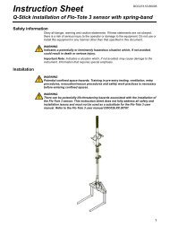
Hang from a cable<br />
N O T I C E<br />
Do not use the handles to hang the logger. The handles are not designed to hold the weight of the logger.<br />
The logger can hang from a cable for installation in an area such as a manhole.<br />
1. Connect a cable to the eye bolts on the top of the logger. Refer to Figure 16.<br />
2. Hang the cable from a strong support such as an optional spanner bar.<br />
Figure 16 Hang the logger from a cable<br />
Install on a wall bracket<br />
The logger can be attached to a wall, pole or ladder. Refer to the documents that are supplied with<br />
the hardware for installation instructions.<br />
Maintenance<br />
W A R N I N G<br />
Multiple hazards. Only qualified personnel must conduct the tasks described in this section of the<br />
document.<br />
<strong>English</strong> 27
W A R N I N G<br />
Biological hazard. Obey safety handling protocols and wear all of the personal protective equipment<br />
required when handling an instrument that may have come in contact with biological hazardous<br />
materials. Wash and decontaminate the instrument with a disinfectant soap solution and rinse with hot<br />
water before maintenance or shipping.<br />
C A U T I O N<br />
Electromagnetic radiation hazard. Make sure that the antenna is kept at a minimum distance of 20 cm<br />
(7.9 in.) from all personnel in normal use. The antenna cannot be co-located or operated in conjunction<br />
with any other antenna or transmitters.<br />
Clean the instrument<br />
Clean the exterior of the instrument with a moist cloth and a mild soap solution and then wipe the<br />
instrument dry.<br />
Replace the batteries<br />
Replace the batteries with the same type and rating. Refer to Install the batteries on page 12 and<br />
Specifications on page 3.<br />
Replace the desiccant<br />
The desiccant is located in the battery compartment. To remove the battery cover, refer to Install the<br />
batteries on page 12. The desiccant absorbs moisture from the air and prevents corrosion to the<br />
instrument components. The desiccant beads change color when they become saturated. Replace<br />
the desiccant when the beads change from a yellow to a green color (refer to Figure 17). As a best<br />
practice, replace the desiccant when the batteries are replaced.<br />
Figure 17 Desiccant replacement<br />
Troubleshooting<br />
If problems occur in the system, try to find whether the problem is with the sensor, the logger or the<br />
cable connections.<br />
• Examine all connections to the sensors. Make sure all connections are tight.<br />
• Remove and examine the sensor connectors for moisture. Clean and dry if necessary.<br />
• Examine the sensors for debris and remove the debris.<br />
• Examine the Event Log for problem events.<br />
28 <strong>English</strong>
Communication failure<br />
If a call was sent to the server but the connection failed, complete the following tasks:<br />
• Disconnect and apply power to the instrument.<br />
• Adjust the antenna to increase the signal strength.<br />
• Log on to the server and make sure that the serial number was entered correctly and that the SVC<br />
used for configuration was recorded correctly.<br />
• Make sure that the communication settings were entered correctly in the <strong>FL900</strong> driver window.<br />
• Connect the logger to the computer and open a communications session. In the <strong>FL900</strong> driver<br />
window, click on the Diagnostics tab and then the Modem menu. The Registration Status should<br />
be Home.<br />
• If there is no resolution, call technical support.<br />
Replacement parts and accessories<br />
Note: Product and Article numbers may vary for some selling regions. Contact the appropriate distributor or refer to<br />
the company website for contact information.<br />
Replacement parts<br />
Description<br />
Item no.<br />
Battery compartment cover 8524400<br />
Desiccant cap assembly (battery compartment desiccant) 8754900<br />
Desiccant tube assembly (battery compartment desiccant) 8535200<br />
Desiccant, replacement beads (1.5 can bulk) 8755500<br />
Eyebolts, 1/4–20 x 2.5-in. stainless steel 8535500<br />
Gasket, top cover 8533300<br />
Logger handle 8524200<br />
Lubricant, silicone 0.25 oz<br />
000298HY<br />
Magnet assembly 8537800<br />
O-ring for battery cover 8533400<br />
Cables<br />
Description<br />
Item no.<br />
Cable, external power, 2-wire, 9 ft 8528700<br />
Cable, external power, 2-wire, 25 ft 8528701<br />
Cable, communication, RS232 8528200<br />
Cable, communication, USB 8528300<br />
Cable, connect to sampler, 9 ft 8528400<br />
Cable, connect to sampler, 25 ft 8528401<br />
<strong>English</strong> 29
Power<br />
Description<br />
Item no.<br />
Battery, 6 V lantern<br />
11013M<br />
Battery, long-life alkaline 8542900<br />
Long-life alkaline battery pack top cap adapter and cable 8543000<br />
Cable, power supply adapter (3 pin to 7 pin) 8528600<br />
Power Supply, 110–120 VAC, US plug—requires 8528600 adapter cable<br />
8754500US<br />
Power Supply, 110–120 VAC, Australia plug—requires 8528600 adapter cable<br />
8754500AU<br />
Power Supply, 110–120 VAC, <strong>EU</strong> plug—requires 8528600 adapter cable<br />
8754500<strong>EU</strong><br />
Power Supply, 110–120 VAC, Italy plug—requires 8528600 adapter cable<br />
8754500IL<br />
Power Supply, 110–120 VAC, UK plug—requires 8528600 adapter cable<br />
8754500UK<br />
Mounting hardware<br />
Description<br />
Item no.<br />
Manhole Support Bracket/Spanner, 18–28 in. 9542<br />
Manhole Support Bracket/Spanner, 28–48 in. 9557<br />
Manhole Support Bracket, 18–27 in. 5713000<br />
Suspension Cable, 16 in. 8544300<br />
Suspension Cable, 30 in. and D-ring (standard) 4920<br />
Wall-mount Bracket with ladder hanger 8544500<br />
Wall-mount Bracket without ladder hanger 8542700<br />
Antennas<br />
Description<br />
Item no.<br />
Antenna, traffic-rated burial (824–960, 1850–1990 MHz) 8537600<br />
Antenna, half-wave (824–894, 1850–1990 MHz)—US 5228400<br />
Antenna, half-wave (870–960, 1710–1880 MHz)—<strong>EU</strong> 5255300<br />
Antenna, traffic-rated manhole lid (824–896, 1850–1990 MHz)—US 5255400<br />
Antenna, mini-wing (824–960, 1710–2170 MHz)—US 6241804<br />
Extension cable, 15 ft 5244000<br />
Extension cable, 70 ft 5249100<br />
External devices<br />
Description<br />
Item no.<br />
Rain Gauge with 100-ft cable 8542800<br />
Connector for Rain Gauge to <strong>FL900</strong> 8547700<br />
AV9000 Analyzer Module (required to attach a Submerged Area/Velocity Sensor) 8531300<br />
30 <strong>English</strong>
External devices (continued)<br />
Description<br />
Item no.<br />
IM9001 Interface Module (required to attach a Sigma 950 Flow Meter) 8549800<br />
For samplers, refer to www.hach.com for part numbers and accessories<br />
<strong>English</strong> 31
32 <strong>English</strong>
OTT Hydromet GmbH<br />
Ludwigstrasse 16<br />
87437 Kempten<br />
Tel. +49 (0)8 31 5617-0<br />
Fax +49 (0)8 31 5617-209<br />
info@ott.com<br />
www.ott.com<br />
OTT France<br />
Europarc de Pichaury – Bât. D2<br />
13799 Aix en Provence Cedex 3<br />
Tél. +33 (0)4 42 90 05 90<br />
Fax +33 (0)4 42 90 05 95<br />
info@ottfrance.fr<br />
www.ottfrance.com<br />
OTT HYDROMETRIE AG<br />
Obere Bahnhofstrasse 13<br />
5507 Mellingen<br />
Tel. +41 (0)56 470 64 34<br />
Fax +41 (0)56 491 21 06<br />
info@ott-schweiz.ch<br />
www.ott-schweiz.ch<br />
OTT Hydromet GmbH<br />
Branch office Austria<br />
Weidegut 76<br />
4223 Katsdorf<br />
Tel. +43 (0)7235 8899-8<br />
Fax +43 (0)7235 8899-1<br />
m.schinnerl@ott.com<br />
www.ott-austria.at<br />
OTT MedioAmbiente<br />
C/Teide, nº 5 - Planta Baja, Local nº 2<br />
Parque Empresarial La Marina<br />
28700 San Sebastián de los Reyes (Madrid)<br />
Tel. +34 (0)91 651 47 69<br />
Fax +34 (0)91 659 02 09<br />
info@ott-medioambiente.com<br />
www.ott-medioambiente.com<br />
OTT Hydrometry Ltd.<br />
Unit 2 Magnet Business Park<br />
14 High Hazels Road, Barlborough<br />
Chesterfield S43 4UZ<br />
Tel. +44 (0)1246 573 480<br />
Fax +44 (0)1246 813 873<br />
sales@ott-hydrometry.co.uk<br />
www.ott-hydrometry.co.uk<br />
© Hach Company/Hach Lange GmbH, 2013.<br />
All rights reserved.