Stormwater Manual - Pima County Flood Control District
Stormwater Manual - Pima County Flood Control District
Stormwater Manual - Pima County Flood Control District

Create successful ePaper yourself
Turn your PDF publications into a flip-book with our unique Google optimized e-Paper software.
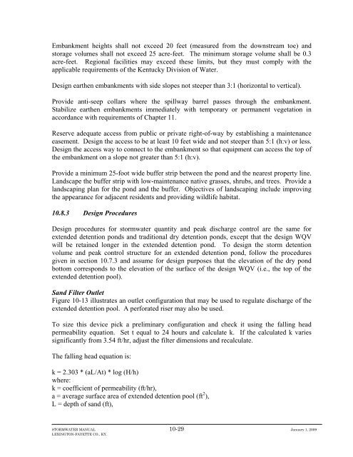
Embankment heights shall not exceed 20 feet (measured from the downstream toe) and<br />
storage volumes shall not exceed 25 acre-feet. The minimum storage volume shall be 0.3<br />
acre-feet. Regional facilities may exceed these limits, but they must comply with the<br />
applicable requirements of the Kentucky Division of Water.<br />
Design earthen embankments with side slopes not steeper than 3:1 (horizontal to vertical).<br />
Provide anti-seep collars where the spillway barrel passes through the embankment.<br />
Stabilize earthen embankments immediately with temporary or permanent vegetation in<br />
accordance with requirements of Chapter 11.<br />
Reserve adequate access from public or private right-of-way by establishing a maintenance<br />
easement. Design the access to be at least 10 feet wide and not steeper than 5:1 (h:v) or less.<br />
Design the access way to connect to the embankment so that equipment can access the top of<br />
the embankment on a slope not greater than 5:1 (h:v).<br />
Provide a minimum 25-foot wide buffer strip between the pond and the nearest property line.<br />
Landscape the buffer strip with low-maintenance native grasses, shrubs, and trees. Provide a<br />
landscaping plan for the pond and the buffer. Objectives of landscaping include improving<br />
the appearance for adjacent residents and providing wildlife habitat.<br />
10.8.3 Design Procedures<br />
Design procedures for stormwater quantity and peak discharge control are the same for<br />
extended detention ponds and traditional dry detention ponds, except that the design WQV<br />
will be retained longer in the extended detention pond. To design the storm detention<br />
volume and peak control structure for an extended detention pond, follow the procedures<br />
given in section 10.7.3 and assume for design purposes that the elevation of the dry pond<br />
bottom corresponds to the elevation of the surface of the design WQV (i.e., the top of the<br />
extended detention pool).<br />
Sand Filter Outlet<br />
Figure 10-13 illustrates an outlet configuration that may be used to regulate discharge of the<br />
extended detention pool. A perforated riser may also be used.<br />
To size this device pick a preliminary configuration and check it using the falling head<br />
permeability equation. Set t equal to 24 hours and calculate k. If the calculated k varies<br />
significantly from 3.54 ft/hr, adjust the filter dimensions and recalculate.<br />
The falling head equation is:<br />
k = 2.303 * (aL/At) * log (H/h)<br />
where:<br />
k = coefficient of permeability (ft/hr),<br />
a = average surface area of extended detention pool (ft 2 ),<br />
L = depth of sand (ft),<br />
STORMWATER MANUAL 10-29 January 1, 2009<br />
LEXINGTON-FAYETTE CO., KY.