BANDIT II C2C - Encore Networks
BANDIT II C2C - Encore Networks
BANDIT II C2C - Encore Networks

You also want an ePaper? Increase the reach of your titles
YUMPU automatically turns print PDFs into web optimized ePapers that Google loves.
encor<br />
! •<br />
enetworks TM<br />
Version A.1, January 2012<br />
© 2012 <strong>Encore</strong> <strong>Networks</strong>, Inc.<br />
All rights reserved.<br />
<strong>BANDIT</strong> <strong>II</strong> <strong>C2C</strong> Hardware Description and<br />
Specifications<br />
This chapter provides information on the hardware and specifications for the <strong>BANDIT</strong> <strong>II</strong><br />
<strong>C2C</strong>. See the following:<br />
• The <strong>BANDIT</strong> <strong>II</strong> <strong>C2C</strong> Chassis<br />
• <strong>BANDIT</strong> <strong>II</strong> <strong>C2C</strong> Specifications<br />
• Ventilation for <strong>BANDIT</strong> Products<br />
A.1 The <strong>BANDIT</strong> <strong>II</strong> <strong>C2C</strong> Chassis<br />
The <strong>BANDIT</strong> <strong>II</strong> <strong>C2C</strong> is available in a chassis with a hard plastic cover, or in an environmentally<br />
hardened chassis, with a metal cover. Hardened construction allows the <strong>BANDIT</strong> <strong>II</strong> <strong>C2C</strong> to operate<br />
over wide temperature ranges at sites that do not use environmental control.<br />
The <strong>BANDIT</strong> <strong>II</strong> <strong>C2C</strong> complies with the European Union’s directive on restriction of hazardous<br />
substances (ROHS). This directive places strict controls on pollutants, including the elimination<br />
of lead in the manufacturing process.<br />
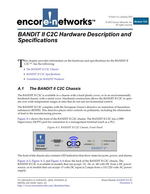
Figure A-1 shows the front of the <strong>BANDIT</strong> <strong>II</strong> <strong>C2C</strong> chassis. The <strong>BANDIT</strong> <strong>II</strong> <strong>C2C</strong> has a DB9<br />
Supervisory (SUPV) port for connection to a management terminal (such as a PC).<br />
Figure A-1. <strong>BANDIT</strong> <strong>II</strong> <strong>C2C</strong> Chassis, Front Panel<br />
The front of the chassis also contains LED indicators that show states for ports, power, and alarms.<br />
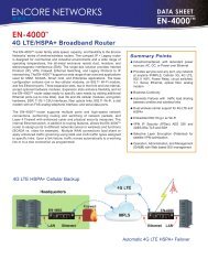
Figure A-2, Figure A-3, and Figure A-4 show the back of the <strong>BANDIT</strong> <strong>II</strong> <strong>C2C</strong> chassis. The<br />
<strong>BANDIT</strong> <strong>II</strong> <strong>C2C</strong> is available in models that can accept -12, -24, or -48 volts DC from a DC power<br />
source, or in models that can accept +5 volts DC input at 2 amps from a 110/220 volts AC power<br />
supply.<br />
For information on trademarks, safety, limitations of<br />
liability, and similar topics, see<br />
http://www.encorenetworks.com/disclaimer.htm.<br />
Home Module: <strong>BANDIT</strong> <strong>II</strong> <strong>C2C</strong><br />
Document A
Page 2<br />
<strong>BANDIT</strong> <strong>II</strong> <strong>C2C</strong> Module, Document A<br />
Figure A-2. <strong>BANDIT</strong> <strong>II</strong> <strong>C2C</strong> Chassis, 12V/24V DC Power, Rear Panel<br />
Figure A-3. <strong>BANDIT</strong> <strong>II</strong> <strong>C2C</strong> Chassis, 24V/48V DC Power, Rear Panel<br />
Figure A-4. <strong>BANDIT</strong> <strong>II</strong> <strong>C2C</strong> Chassis, AC Power, Rear Panel<br />
The following items are on the back of the <strong>BANDIT</strong> <strong>II</strong> <strong>C2C</strong> chassis:<br />
• Two ports for antennas for the cellular wireless card, for connection to a wireless network<br />
Note: A second antenna can provide diversity in data collection. This is helpful when<br />
radiofrequency signals might encounter barriers or interference, or when the signal<br />
level might be low.<br />
• A port for -12, -24, or -48 volts DC power source input or a port for a 110/220 volts AC<br />
power supply, converting power input to +5 volts DC at 2 amps<br />
• A DB25 serial port<br />
• An Ethernet port that can function as one of the following:<br />
- A WAN port, typically used as the network uplink to the host<br />
- A LAN port, typically used for the intranet connection
<strong>BANDIT</strong> <strong>II</strong> <strong>C2C</strong> Hardware Description and Specifications Page 3<br />
• An analog modem port<br />
Note: The <strong>BANDIT</strong> <strong>II</strong> <strong>C2C</strong> chassis also contains a wireless modem port (on the<br />
internal wireless card). However, because that port is internal, it cannot be seen on the<br />
back of the chassis. The internal wireless card can connect to a 2G, 3G, or 4G/LTE<br />
wireless network. External antennas support the wireless card.<br />
• One earth ground connection bolt<br />
For additional information, see the following:<br />
• Power Supply<br />
• Ports<br />
• LEDs<br />
A.1.1<br />
Power Supply<br />
The <strong>BANDIT</strong> <strong>II</strong> <strong>C2C</strong> is available in models that accept power from a DC power source at -12,<br />
-24, or -48 VDC or in models that accept power from an industry-standard autosensing 100/<br />
240 VAC adapter connected to an AC power source. The <strong>BANDIT</strong> <strong>II</strong> <strong>C2C</strong>’s AC power supply<br />
converts the AC input power to 5 VDC at 2 amps output for use by the <strong>BANDIT</strong> <strong>II</strong> <strong>C2C</strong><br />
chassis.<br />
A.1.2<br />
Ports<br />
See the following:<br />
• Supervisory Port<br />
• Modem Ports<br />
• Standard Network Ports<br />
A.1.2.1<br />
Supervisory Port<br />
A DB9 cable connects the <strong>BANDIT</strong> <strong>II</strong> <strong>C2C</strong>’s DB9 Supervisory port to the DB9 serial port of a<br />
computer functioning as a control console (such as a PC). The DB9 cable provides a direct<br />
connection to the <strong>BANDIT</strong> <strong>II</strong> <strong>C2C</strong>, for configuring and monitoring the device.<br />
After you give the <strong>BANDIT</strong> <strong>II</strong> <strong>C2C</strong> an IP address, you can decide whether to configure and<br />
monitor the <strong>BANDIT</strong> <strong>II</strong> <strong>C2C</strong> via a remote connection over the LAN or WAN. This frees the<br />
serial DB9 port to support data connections.<br />
For specifications of the DB9 serial port, see Section A.2.1.2.1, DB9 Supervisory Port, in<br />
<strong>BANDIT</strong> <strong>II</strong> <strong>C2C</strong> Specifications.<br />
A.1.2.2<br />
Modem Ports<br />
The <strong>BANDIT</strong> <strong>II</strong> <strong>C2C</strong> has two modem ports. The modem port on the back of the chassis uses<br />
a standard RJ11 connector. (For specifications of the RJ11 port, see RJ11 Modem Port in<br />
<strong>BANDIT</strong> <strong>II</strong> <strong>C2C</strong> Specifications.) The <strong>BANDIT</strong> <strong>II</strong> <strong>C2C</strong>’s other modem port is internal, on the<br />
wireless card inside the chassis.
Page 4<br />
<strong>BANDIT</strong> <strong>II</strong> <strong>C2C</strong> Module, Document A<br />
A.1.2.3<br />
Standard Network Ports<br />
Note: The <strong>BANDIT</strong>’s data ports can be configured in the software. The data rates for<br />
synchronous and asynchronous data ports are shown in Table A-9 and Table A-10 in<br />
<strong>BANDIT</strong> <strong>II</strong> <strong>C2C</strong> Specifications. See the following:<br />
• Ethernet Port<br />
• Serial Port<br />
• Wireless Port<br />
A.1.2.3.1<br />
Ethernet Port<br />
The <strong>BANDIT</strong> <strong>II</strong> <strong>C2C</strong> has one Ethernet port that can connect to a LAN or a WAN. A<br />
10-Base-T/100-Base-T Ethernet connection is implemented over unshielded twisted-pair<br />
(UTP) wire, using a standard RJ45 connector. Figure A-8 shows the RJ45 connector pins.<br />
Table A-8 lists the RJ45 pin configuration. Table A-4 shows the interface options for the<br />
Ethernet port.<br />
Also see Port Throughput.<br />
The Ethernet port has the following IP features:<br />
• Static routing<br />
• Standard RIP V1, V2 routing<br />
• Prioritization on Layers 2 and 3<br />
• DiffServ marking and classification for end-to-end prioritization<br />
• IP Quality of Service<br />
• Dynamic bandwidth allocation<br />
• 802.1q VLAN tagging<br />
• VRRP (RFC 3768)<br />
• Fragmentation and reassembly (MTU) LAN<br />
• DHCP server, client, relay; Bootp<br />
• SNMP, MIB <strong>II</strong><br />
• ARP; Proxy ARP<br />
• Routing over VPN tunnels<br />
• Dynamic split tunneling<br />
A.1.2.3.2<br />
Serial Port<br />
The <strong>BANDIT</strong> <strong>II</strong> <strong>C2C</strong> chassis has one DB25 serial port. See DB25 Serial Port in <strong>BANDIT</strong> <strong>II</strong> <strong>C2C</strong><br />
Specifications.<br />
Note: The DB9 Supervisory port is also a serial port. See Supervisory Port.<br />
A.1.2.3.3<br />
Wireless Port<br />
The <strong>BANDIT</strong> <strong>II</strong> <strong>C2C</strong> has one internal wireless port. The <strong>BANDIT</strong> <strong>II</strong> <strong>C2C</strong> can use a wireless<br />
card for 2G, 3G, or 4G/LTE transport.
<strong>BANDIT</strong> <strong>II</strong> <strong>C2C</strong> Hardware Description and Specifications Page 5<br />
A.1.3<br />
LEDs<br />
Light-emitting diodes (LEDs) on the front of the <strong>BANDIT</strong> <strong>II</strong> <strong>C2C</strong> chassis indicate states,<br />
connections, and activities. The following sections describe the LEDs.<br />
• General Status LEDs<br />
• Protocol Status LEDs<br />
A.1.3.1<br />
General Status LEDs<br />
The following general rules apply to the <strong>BANDIT</strong> products’ LEDs:<br />
• A lit green Power/Alarm LED indicates that the unit is being supplied with power.<br />
• Other lit green LEDs indicate that there is a connection to another device—for example,<br />
a terminal device, an Ethernet hub, a switch, or a cellular wireless tower.<br />
• A flashing LED indicates a special state, which may vary for each type of LED. See<br />
Table A-1 for information about blinking for specific LEDs.<br />
Table A-1 describes the LEDs on the <strong>BANDIT</strong> <strong>II</strong> <strong>C2C</strong> chassis.<br />
Table A-1. <strong>BANDIT</strong> <strong>II</strong> <strong>C2C</strong> General Status LED Definitions (Sheet 1 of 2)<br />
LED Color Description<br />
Power/Alarm Green<br />
Unit is receiving power.<br />
(System)<br />
Green blinking A port has an alarm or the system needs attention.<br />
Supervisory<br />
port<br />
LAN/WAN<br />
port<br />
CO Modem<br />
port<br />
Off<br />
Green<br />
Off<br />
Green<br />
Off<br />
Green<br />
Off<br />
Unit is not receiving power.<br />
Connection has been made to the management<br />
terminal (or to a network device, if the Supervisory<br />
port is used for data instead of management).<br />
There is no connection.<br />
Connection to the LAN or the WAN has been made.<br />
(That is, the <strong>BANDIT</strong> device is connected to another<br />
device that is powered on in the network.)<br />
There is no connection to the network.<br />
Check cables and check that connected devices have<br />
power.<br />
Connection to the analog device has been made.<br />
(The <strong>BANDIT</strong> device is acting as a modem to<br />
support an analog device.)<br />
There is no connection to the analog device.<br />
Check cables and check that connected devices have<br />
power.
Page 6<br />
<strong>BANDIT</strong> <strong>II</strong> <strong>C2C</strong> Module, Document A<br />
Table A-1. <strong>BANDIT</strong> <strong>II</strong> <strong>C2C</strong> General Status LED Definitions (Sheet 2 of 2)<br />
LED Color Description<br />
Cellular port Green Connection has been made to a wireless carrier.<br />
(Flashing)<br />
Off<br />
The cellular LED flashes one to five times to show<br />
signal strength. The number of flashes in a set is<br />
equivalent to the same number of bars displaying<br />
signal strength on a mobile phone.<br />
Flashes display in one of the following patterns:<br />
• A set of short flashes followed by a longer final<br />
flash indicates that connection to a cell tower has<br />
been authenticated. Sample flash pattern:<br />
_ _ _ _ ` _ _ _ _ ` _ _ _ _<br />
• A set of short flashes followed by a pause<br />
indicates that there is a signal from a cell tower<br />
but that the connection has not been<br />
authenticated. The device may need to be<br />
activated. Sample flash pattern:<br />
_ _ _ _ ` _ _ _ _ ` _ _ _ _<br />
The number of short flashes in a set indicates the<br />
signal strength. A long flash is not counted as part<br />
of the signal strength.<br />
Not activated. The device has not been<br />
authenticated for a wireless carrier and is not<br />
receiving a signal.<br />
A.1.3.2<br />
Protocol Status LEDs<br />
In addition to indicating general status, each port’s LED indicates conditions for the protocol<br />
configured on that port. Table A-2 describes the LEDs for protocols the <strong>BANDIT</strong> <strong>II</strong> <strong>C2C</strong><br />
supports.<br />
Table A-2. <strong>BANDIT</strong> <strong>II</strong> <strong>C2C</strong> Protocol Status LED Definitions (Sheet 1 of 2)<br />
Protocol<br />
Frame Relay<br />
Async Encapsulation<br />
Bit Sync Encapsulation<br />
Async/Sync PPP<br />
SLIP<br />
SDLC Emulation, Terminal 1<br />
SDLC Emulation, Host 1<br />
SDLC Routing<br />
Annex G<br />
Green LED<br />
If a Frame Relay Management protocol connection is up, the<br />
LED lights after 15–20 seconds. (If there is no connection, the<br />
LED remains unlit.)<br />
Characters, bidirectional TD/RD<br />
Frames in either direction<br />
Frames to/from port<br />
Frames to/from port<br />
Sending or receiving data<br />
The host has a transport layer connection with a terminal listed<br />
in the device table.<br />
Frames to/from port<br />
Good frames are passing through.
<strong>BANDIT</strong> <strong>II</strong> <strong>C2C</strong> Hardware Description and Specifications Page 7<br />
Table A-2. <strong>BANDIT</strong> <strong>II</strong> <strong>C2C</strong> Protocol Status LED Definitions (Sheet 2 of 2)<br />
Protocol<br />
Green LED<br />
Byte Sync Encapsulation Good frames are passing through.<br />
X.25 Level <strong>II</strong> connection exists.<br />
Telnet Terminal<br />
Data transfer in either direction<br />
1. When using spoofed protocols such as SDLC, both LEDs can light up at the same time. On a terminal<br />
unit, both LEDs may be lit if some terminals are responding and some are not. On a host unit, both LEDs<br />
may light up if some terminals are being polled and some are not.<br />
A.2 <strong>BANDIT</strong> <strong>II</strong> <strong>C2C</strong> Specifications<br />
This section lists the specifications for the <strong>BANDIT</strong> <strong>II</strong> <strong>C2C</strong> hardware. See the following:<br />
• Section A.2.1, Chassis Specifications<br />
• Section A.2.2, Management Support<br />
• Section A.2.3, Compliance<br />
Specifications are subject to change without notice.<br />
A.2.1<br />
Chassis Specifications<br />
The following sections cover the physical, power, and environmental specifications for the<br />
<strong>BANDIT</strong> <strong>II</strong> <strong>C2C</strong> chassis. See the following:<br />
• Section A.2.1.1, Physical Specifications<br />
• Section A.2.1.2, Ports and Pin Configurations<br />
• Section A.2.1.3, Power<br />
• Section A.2.1.4, Environmental Specifications<br />
A.2.1.1<br />
Physical Specifications<br />
The products in the <strong>BANDIT</strong> family are designed for quick and easy integration with other<br />
equipment in a typical networking environment. Table A-3 provides the physical<br />
specifications for the <strong>BANDIT</strong> <strong>II</strong> <strong>C2C</strong>.<br />
Table A-3. <strong>BANDIT</strong> <strong>II</strong> <strong>C2C</strong> Physical Specifications (Sheet 1 of 2)<br />
Item<br />
Installation Type<br />
Length<br />
Width<br />
Value<br />
Desktop/Shelf Model<br />
6.0 in. (15.24 cm)<br />
4.4 in. (11.18 cm)
Page 8<br />
<strong>BANDIT</strong> <strong>II</strong> <strong>C2C</strong> Module, Document A<br />
Table A-3. <strong>BANDIT</strong> <strong>II</strong> <strong>C2C</strong> Physical Specifications (Sheet 2 of 2)<br />
Item<br />
Height 1, 2<br />
Weight<br />
Value<br />
1.5 in. (3.81 cm)<br />
Less than 1 lb. (Less than 0.45 kg)<br />
1. The chassis must have adequate ventilation for cooling. There must be an open vertical space<br />
of 1 U (1.75 inches, or 44.45 mm) above the chassis, and there must be nothing between the chassis<br />
and the desk surface or shelf surface that the chassis feet rest on. Do not place anything on top of<br />
the chassis or under the chassis.<br />
2. When the height of the chassis feet is included, the chassis stands 0.03 inches (0.076 cm) taller,<br />
at 1.53 in. (3.886 cm).<br />
A.2.1.2<br />
Ports and Pin Configurations<br />
Table A-4 lists the port interfaces in the <strong>BANDIT</strong> <strong>II</strong> <strong>C2C</strong>. See the following for information<br />
about ports and pin configurations:<br />
◆ Section A.2.1.2.1, DB9 Supervisory Port<br />
◆ Section A.2.1.2.2, DB25 Serial Port<br />
◆ Section A.2.1.2.3, RJ11 Modem Port<br />
◆ Section A.2.1.2.4, RJ45 10-Base-T/100-Base-T Ethernet Port<br />
◆ Section A.2.1.2.5, Port Throughput<br />
◆ Section A.2.1.2.6, Port Speeds<br />
Table A-4. <strong>BANDIT</strong> <strong>II</strong> <strong>C2C</strong> Physical Interfaces and Connectivity (Sheet 1 of 2)<br />
Port Quantity Interface Connectivity<br />
Supervisory<br />
port<br />
Analog<br />
modem port<br />
1 DB9 RS232<br />
1 RJ11 Analog modem:<br />
• Bell103, Bell212, V.21, V.22, V.22bis,<br />
V.23, V.32, V.32bis, V.34<br />
•LS/GS<br />
•Polarity reversal<br />
• V.42 with error correction and<br />
MNP 2-4<br />
• V.42bis with Data Compression and<br />
MNPS<br />
Internal<br />
wireless<br />
port<br />
1 integrated cellular<br />
wireless modem<br />
2G, 3G, and 4G/LTE 1 cellular wireless<br />
data networks
<strong>BANDIT</strong> <strong>II</strong> <strong>C2C</strong> Hardware Description and Specifications Page 9<br />
Table A-4. <strong>BANDIT</strong> <strong>II</strong> <strong>C2C</strong> Physical Interfaces and Connectivity (Sheet 2 of 2)<br />
Port Quantity Interface Connectivity<br />
Ethernet<br />
port<br />
1 RJ45, 10/100 Base-T<br />
Ethernet, with<br />
automatic failover, to<br />
connect to LAN or<br />
WAN<br />
IP:<br />
• TCP, UDP/RTP Data Transport<br />
• TCP Port configuration<br />
•TCP Broadcast<br />
• RTP Packet Optimization<br />
• DLCI over IP configuration<br />
• Telnet (Client or Server)<br />
serial port 1 DB25, RS232 (256 kbps<br />
sync, 230 kbps async)<br />
Frame Relay:<br />
• Link Management<br />
- LMI, CCITT, Q.933 Annex A;<br />
- ANSI T1.617 Annex D<br />
• IP over Frame Relay<br />
• CIR Enforcement<br />
• Fragmentation FRF12<br />
• Fast Connection<br />
• Prioritization<br />
•Unicasting<br />
•Multicasting<br />
PPP, Multilink PPP:<br />
• Sync PPP<br />
•Async PPP<br />
• MLPPP<br />
•PAP<br />
•CHAP<br />
• IP over PPP<br />
IP: All standard IP features<br />
X.25: All standard X.25 features<br />
1. Consult manufacturer for availability.<br />
A.2.1.2.1<br />
DB9 Supervisory Port<br />
Figure A-5 identifies the pin locations for a female DB9 connector. Table A-5 lists the<br />
standard DB9 pin configuration.<br />
Figure A-5. Pin Locations for Female DB9 Serial Port
Page 10<br />
<strong>BANDIT</strong> <strong>II</strong> <strong>C2C</strong> Module, Document A<br />
Table A-5. DB9 Serial Port Pin Configuration<br />
Pin Number 1 (only DCE) Description<br />
EIA 2<br />
Signal<br />
1 DCD Data carrier detect<br />
2 RXD Received data<br />
3 TXD Transmitted data<br />
4 DTR Data terminal ready<br />
5 GND Signal ground<br />
7 RTS Request to send<br />
8 CTS Clear to send<br />
1. Unused pins are not listed.<br />
2. EIA = Electronic Industries Alliance<br />
A.2.1.2.2<br />
DB25 Serial Port<br />
Figure A-6 identifies the pin locations for a female DB25 connector.<br />
Note: On the <strong>BANDIT</strong> <strong>II</strong> <strong>C2C</strong>, you use the ELIOS software to set the DB25 serial port as<br />
DCE or DTE.<br />
Figure A-6. Pin Locations for Female DB25 Serial Port<br />
Table A-6 lists the pin configuration for the <strong>BANDIT</strong> <strong>II</strong> <strong>C2C</strong>’s standard DB25 port.<br />
Table A-6. DB25 Serial Port Pin Configuration<br />
Pin Number 1<br />
Pin 1<br />
EIA 2 Signal<br />
(DCE or<br />
DTE 3 )<br />
Description<br />
Shield (Earth Ground)<br />
Pin 2 TXD Transmitted data<br />
Pin 3 RXD Received data<br />
Pin 4 RTS Request to send<br />
Pin 5 CTS Clear to send<br />
Pin 6 DSR Data set ready<br />
Pin 7 GND Signal ground<br />
Pin 8 DCD Data carrier detect<br />
Pin 15 TXC Transmit clock<br />
Pin 17 RXC Receive clock<br />
Pin 20 DTR Data terminal ready<br />
Pin 24 SCTE External clock<br />
1. Unused pins are not listed.<br />
2. EIA = Electronic Industries Alliance<br />
3. You use the <strong>BANDIT</strong> <strong>II</strong> <strong>C2C</strong>’s ELIOS software to select DCE or DTE for this port.
<strong>BANDIT</strong> <strong>II</strong> <strong>C2C</strong> Hardware Description and Specifications Page 11<br />
A.2.1.2.3<br />
RJ11 Modem Port<br />
Figure A-7 shows the pin locations for the modem port. Table A-7 lists the pin configuration<br />
for the <strong>BANDIT</strong> <strong>II</strong> <strong>C2C</strong>’s RJ11 modem port.<br />
Figure A-7. Pin Locations for Female RJ11 Modem Port<br />
Table A-7. RJ11 Modem Port Pin Configuration<br />
Pin Number 2<br />
Function<br />
2 Ring<br />
3 Tip<br />
2. Unused pins are not listed.<br />
A.2.1.2.4<br />
RJ45 10-Base-T/100-Base-T Ethernet Port<br />
Figure A-8 shows the pin locations on an RJ45 Ethernet port. Table A-8 lists the pin<br />
configuration for the <strong>BANDIT</strong> <strong>II</strong> <strong>C2C</strong>’s 10/100-Base-T Ethernet ports.<br />
Note: The <strong>BANDIT</strong> <strong>II</strong> <strong>C2C</strong> senses the pin configuration at the remote end of the connection<br />
and sets its own pin configuration accordingly.<br />
Figure A-8. Pin Locations for Female RJ45 Ethernet Port<br />
Table A-8. RJ45 10-Base-T/100-Base-T Ethernet Port Pin Configuration<br />
Pin Set 1 Description 2<br />
Pin 1 and Pin 2<br />
Tx or Rx<br />
Pin 3 and Pin 6<br />
Rx or Tx<br />
1. Unused pins are not listed.<br />
2. The <strong>BANDIT</strong> <strong>II</strong> <strong>C2C</strong> Ethernet connectors are autosensing and will adjust to the signals<br />
from the device at the remote end of the connection.
Page 12<br />
<strong>BANDIT</strong> <strong>II</strong> <strong>C2C</strong> Module, Document A<br />
A.2.1.2.5<br />
Port Throughput<br />
The <strong>BANDIT</strong> <strong>II</strong> <strong>C2C</strong> chassis has the following system throughput:<br />
• Without encryption: 9,000 packets/second, with incoming and outgoing traffic at<br />
64 bytes/packet<br />
• With encryption and decryption: 1,800 packets/second, with incoming traffic at<br />
50 bytes/packet and outgoing traffic at 100 bytes/packet<br />
A.2.1.2.6<br />
Port Speeds<br />
For all serial ports, speeds of more than 230 kbps are not supported. The serial ports can<br />
support asynchronous speeds down to 50 bps.<br />
For all ports, the synchronous speed range is 2400 bps (2.4 kbps) to 256 kbps.<br />
Table A-9 and Table A-10 provide details for port speeds.<br />
Table A-9. Synchronous Port Speeds<br />
Synchronous (Bits/Second)<br />
256,000<br />
192,000<br />
128,000<br />
96,000<br />
64,000<br />
56,000<br />
48,000<br />
38,400<br />
19,200<br />
9,600<br />
4,800<br />
2,400<br />
Table A-10. Asynchronous Port Speeds<br />
Asynchronous (Bits/Second)<br />
230,400<br />
115,200<br />
57,600<br />
48,000<br />
38,400<br />
19,200<br />
9,600<br />
4,800<br />
2,400<br />
1,200<br />
600<br />
300<br />
200<br />
110<br />
50
<strong>BANDIT</strong> <strong>II</strong> <strong>C2C</strong> Hardware Description and Specifications Page 13<br />
A.2.1.3<br />
Power<br />
The <strong>BANDIT</strong> <strong>II</strong> <strong>C2C</strong> chassis accepts DC input power from a DC power source or from an<br />
external power supply that uses AC input.<br />
As shown in Table A-11, the DC power source can provide -12, -24, or -48 volts DC. The AC<br />
power supply accepts input power at 110 to 220 volts AC, 50 to 60 Hz, auto-ranging, and<br />
delivers 5 volts DC at 2 amps output to the <strong>BANDIT</strong> <strong>II</strong> <strong>C2C</strong> chassis.<br />
Table A-11. <strong>BANDIT</strong> <strong>II</strong> <strong>C2C</strong> Power Specifications<br />
Item<br />
<strong>BANDIT</strong> <strong>II</strong> <strong>C2C</strong> chassis with analog<br />
modem and integrated cellular<br />
modem<br />
• DC power supply<br />
• AC power supply 1<br />
Specification<br />
7.5 watt maximum<br />
-12 VDC,<br />
-24 VDC, or<br />
-48 VDC<br />
100 VAC to 240 VAC, 50 Hz to 60 Hz<br />
1. with external adapter to connect to AC outlet<br />
A.2.1.4<br />
Environmental Specifications<br />
Table A-12 provides the environmental specifications for the <strong>BANDIT</strong> <strong>II</strong> <strong>C2C</strong>.<br />
Table A-12. <strong>BANDIT</strong> <strong>II</strong> <strong>C2C</strong> Environmental Specifications<br />
Item Chassis or Card Range<br />
Operating Temperature<br />
Non-Operating (Storage)<br />
Temperature<br />
Industrially hardened<br />
chassis 1<br />
Commercial grade<br />
chassis 2<br />
Cellular wireless card<br />
All<br />
DC: -40°C to +85°C (-40°F to 185°F)<br />
AC: -30°C to +70°C (-22°F to 158°F)<br />
0°C to +50°C (32°F to 122°F)<br />
-40°C to +70°C (-40°F to 158°F)<br />
-40°C to +85°C (-40°F to 185°F)<br />
Humidity All 5% to 95%, non-condensing<br />
Altitude All Up to 10,000 ft. (up to 3,048 m)<br />
1. All <strong>BANDIT</strong> <strong>II</strong> <strong>C2C</strong> chassis that use -12, -24, or -48 V DC power sources are industrial grade.<br />
Some <strong>BANDIT</strong> <strong>II</strong> <strong>C2C</strong> chassis that use AC power sources are industrial grade.<br />
2. All commercial grade <strong>BANDIT</strong> <strong>II</strong> <strong>C2C</strong> chassis use AC power sources.
Page 14<br />
<strong>BANDIT</strong> <strong>II</strong> <strong>C2C</strong> Module, Document A<br />
A.2.2<br />
Management Support<br />
Table A-13. <strong>BANDIT</strong> <strong>II</strong> <strong>C2C</strong> Software Management<br />
Port<br />
Supervisory port<br />
WAN Ethernet port<br />
Management<br />
Local management via terminal emulation<br />
Remote management via Telnet or SNMP<br />
A.2.3<br />
Compliance<br />
The <strong>BANDIT</strong> <strong>II</strong> <strong>C2C</strong> complies with the North American Electric Reliability Corporation’s<br />
provisions for critical infrastructure protection (NERC CIP). The <strong>BANDIT</strong> <strong>II</strong> <strong>C2C</strong> also<br />
complies with the agency standards listed in Table A-14.<br />
Table A-14. <strong>BANDIT</strong> <strong>II</strong> <strong>C2C</strong> Standards Compliance<br />
Area<br />
Product Materials<br />
Electromagnetic<br />
Compatibility (EMC)<br />
Specification<br />
European ROHS<br />
FCC Part 15<br />
EN 55022: 1998<br />
EN 55024: 1998<br />
Product Safety UL/CSA 60950-1<br />
CAN/CSA-C22.2 No. 60950-1-03<br />
EN 60950-1<br />
A.3 Ventilation for <strong>BANDIT</strong> Products<br />
There must be sufficient space for ventilation and cooling around each chassis in the<br />
<strong>BANDIT</strong> product family. Guidelines for ventilation include the following:<br />
• Each desktop or tabletop chassis (for example, a <strong>C2C</strong> or a <strong>BANDIT</strong> <strong>II</strong> <strong>C2C</strong>) must sit on a<br />
smooth, flat, non-cloth, non-paper surface, so that there is adequate ventilation under the<br />
chassis.<br />
• There must be 1 U (1.75 inches) of empty space above and below each <strong>BANDIT</strong>, VSR, or<br />
RDU chassis installed in an equipment rack.<br />
• Do not place anything on top of any chassis.<br />
• Do not place anything against any chassis, and do not allow anything to rest against the<br />
chassis.