Protocols: Point-to-Point Protocol Configuration - Encore Networks
Protocols: Point-to-Point Protocol Configuration - Encore Networks
Protocols: Point-to-Point Protocol Configuration - Encore Networks

You also want an ePaper? Increase the reach of your titles
YUMPU automatically turns print PDFs into web optimized ePapers that Google loves.
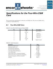
Page 2 <strong>Pro<strong>to</strong>cols</strong> Module, Document 6Router56K CSU/DSUFRAD56K CSU/DSUEthernet192.1.1.3192.1.1.2WorkstationFigure 6-1. PPP over a Dedicated Link• Remote Access via Dial-up Connection. In this scenario (Figure 6-2), users can access anoffice LAN via dial-up connections using a modem or a terminal adapter. The networkcould be a POTS network. If desired, the unit can then carry the PPP traffic over anyconnection <strong>to</strong> the ISP.ISPFrame RelayPPPMikeStandAlone PCNetworkPPPPPPFRADEthernetTIMLocal Area NetworkFigure 6-2. Remote Access via Dial-up Connection• Serving as RIP Interface. PPP can act as a RIP Interface <strong>to</strong> detect new routes from arouter (Figure 6-3).
<strong>Point</strong>-<strong>to</strong>-<strong>Point</strong> Pro<strong>to</strong>col <strong>Configuration</strong> Page 3Figure 6-3. PPP as RIP InterfaceHow <strong>to</strong> Configure PPPNote: To successfully route data through the unit, you must complete the IP Routing Table.See Section 1.1, Routing. And, <strong>to</strong> use IP routing, you must configure the local IP address. SeeSection 4.2, Identifying the BANDIT in the Network.Main Menu----------1) QuickStart Config Builder2) Typical <strong>Configuration</strong>s3) Advanced <strong>Configuration</strong>s4) ToolsV) View Current Unit StatusF) Cellular Fast ConnectL) Load Fac<strong>to</strong>ry DefaultsP) Load Plug and Play DefaultsW) Write <strong>Configuration</strong>R) Reset UnitX) eXit SessionS) StatisticsY) sYstem AdministrationEnter Choice :1 From the Main Menu, select Advanced <strong>Configuration</strong>s.❖ The Advanced <strong>Configuration</strong>s Menu is displayed.
Page 4 <strong>Pro<strong>to</strong>cols</strong> Module, Document 6Advanced <strong>Configuration</strong>s------------------------1) Physical <strong>Configuration</strong>s2) Data <strong>Configuration</strong>s3) Local Address4) Routing5) Global PathsEnter Choice :2 On the Advanced <strong>Configuration</strong>s Menu, select Data <strong>Configuration</strong>s.❖ The Logical Port Pro<strong>to</strong>col Menu is displayed.Logical Port Pro<strong>to</strong>col Attached To Port Interfaces------------------------------------------------------------------------C) Comm/Supervisor Comm/Sup DCEM) <strong>Point</strong>-<strong>to</strong>-<strong>Point</strong> MODEM INTERNALL) EtherNet DHCP Server 192.168.10.1 ETHERNETW) EtherNet DHCP Client 0.0.0.0 ETHERNETS) Frame Relay SERIALB) RDU/IDU Ports...1) Ports 1 <strong>to</strong> 202) Ports 21 <strong>to</strong> 403) Ports 41 <strong>to</strong> 604) Ports 61 <strong>to</strong> 75Enter Port :3 On the Logical Port Pro<strong>to</strong>col Menu, select a port.❖ The port’s Logical Port Attribute Menu is displayed.Serial PortLogical Port Attribute Menu----------------------------1) Pro<strong>to</strong>col : Frame Relay2) Global Paths3) Undefine Current Logical PortEnter Choice :CSU/DSU PortLogical Port Attribute Menu----------------------------1) Pro<strong>to</strong>col : <strong>Point</strong>-<strong>to</strong>-<strong>Point</strong>2) Global Paths3) Undefine Current Logical PortEnter Choice :
<strong>Point</strong>-<strong>to</strong>-<strong>Point</strong> Pro<strong>to</strong>col <strong>Configuration</strong> Page 5Ethernet PortLogical Port Attribute Menu----------------------------1) Pro<strong>to</strong>col : EtherNet2) DHCP Type : DHCP Client3) VLAN Tagging Parameters : No VLAN Tagging4) MAC Filters5) Undefine Current Logical PortEnter Choice :4 If the Logical Port Attribute Menu shows the Pro<strong>to</strong>col as <strong>Point</strong>-<strong>to</strong>-<strong>Point</strong>, go <strong>to</strong> Step 5.Otherwise, do the following:a On the Logical Port Attribute Menu, select Undefine Current Logical Port.❖ The Logical Port Attribute Menu is redisplayed, with pro<strong>to</strong>col undefined.Serial PortLogical Port Attribute Menu----------------------------1) Pro<strong>to</strong>col : UNDEFINED2) Global Paths3) Undefine Current Logical PortEnter Choice : 1CSU/DSU PortLogical Port Attribute Menu----------------------------1) Pro<strong>to</strong>col : <strong>Point</strong>-<strong>to</strong>-<strong>Point</strong>2) Global Paths3) Undefine Current Logical PortEnter Choice :Ethernet PortLogical Port Attribute Menu----------------------------1) Pro<strong>to</strong>col : UNDEFINED2) DHCP Type : DHCP Client3) VLAN Tagging Parameters : No VLAN Tagging4) MAC Filters5) Undefine Current Logical PortEnter Choice :b Then, on the Logical Port Attribute Menu, select Pro<strong>to</strong>col.❖ The list of pro<strong>to</strong>cols available for the port is displayed.
Page 6 <strong>Pro<strong>to</strong>cols</strong> Module, Document 6Serial PortLogical Port Pro<strong>to</strong>col Selection Menu-------------------------------------1) Frame Relay2) <strong>Point</strong>-<strong>to</strong>-<strong>Point</strong> (PPP)3) MultiLink PPP4) X.25+5) SDLC Routing6) SDLC 1490 <strong>Configuration</strong>7) Byte Sync Encapsulation8) ALC9) Bit Sync EncapsulationA) Asynchronous EncapsulationB) Serial Line IP (SLIP)C) Async Burroughs Poll/SelectD) Sync Burroughs Poll/SelectE) BisyncF) Telnet TerminalG) XXX PADH) X.42 SpoofingI) Diagnostic AsyncJ) CDCK) Voice/PCM EncapsulationEnter Choice : 2 <strong>Point</strong>-<strong>to</strong>-<strong>Point</strong>CSU/DSU PortLogical Port Pro<strong>to</strong>col Selection Menu-------------------------------------1) Frame Relay2) <strong>Point</strong>-<strong>to</strong>-<strong>Point</strong> (PPP)3) MultiLink PPP4) X.25+5) ALC6) Bit Sync Encapsulation7) X.42 Spoofing8) Diagnostic Async9) CDCA) Voice/PCM EncapsulationEnter ChoiceEthernet PortLogical Port Pro<strong>to</strong>col Selection Menu-------------------------------------1) PPPoE(PPP over Ethernet)2) ALC3) EtherNet <strong>Configuration</strong>4) X.42 Spoofing5) Diagnostic Async6) CDC7) Voice/PCM EncapsulationEnter Choice :
<strong>Point</strong>-<strong>to</strong>-<strong>Point</strong> Pro<strong>to</strong>col <strong>Configuration</strong> Page 7c On the port’s Logical Port Pro<strong>to</strong>col Selection Menu, select <strong>Point</strong>-<strong>to</strong>-<strong>Point</strong> (PPP) or, if thisis an Ethernet port (LAN or WAN) select PPPoE (<strong>Point</strong>-<strong>to</strong>-<strong>Point</strong> over Ethernet).❖ The PPP Config Parameters Menu is displayed.Serial PortPPP Config Parameters : SERIAL-------------------------------------1) Type : Synchronous PPP2) Synchronous Speed : 96003) IP Address <strong>Configuration</strong>4) LQM Moni<strong>to</strong>ring : Disable5) LQM Percentage : 706) LQM Timer : 1207) MRU : 15008) PPP Authentication <strong>Configuration</strong>Enter Choice : 1CSU/DSU PortPPP Config Parameters : EXPANSION-------------------------------------1) Type : Synchronous PPP2) Synchronous Speed : 96003) IP Address <strong>Configuration</strong>4) LQM Moni<strong>to</strong>ring : Disable5) LQM Percentage : 706) LQM Timer : 1207) MRU : 15008) PPP Authentication <strong>Configuration</strong>Enter Choice : 1Ethernet PortPPP Config Parameters : WAN-------------------------------------1) Type : PPP over Ethernet(PPPOE)2) IP Address <strong>Configuration</strong>3) LQM Moni<strong>to</strong>ring : Disable4) LQM Percentage : 705) LQM Timer : 1206) MRU : 14927) PPP Authentication <strong>Configuration</strong>Enter Choice :d Go <strong>to</strong> Step 6.5 Select Pro<strong>to</strong>col.❖ The PPP Config Parameters Menu is displayed. (See the screens under Step 4c.)6 On the PPP Config Parameters Menu, configure each item as needed, described inStep 7 through Step 14.
Page 8 <strong>Pro<strong>to</strong>cols</strong> Module, Document 67 Select Type. If this is an Ethernet port, the type specifies PPP over Ethernet. Otherwise,this parameter specifies whether the PPP connection is Asynchronous or Synchronous.Note: Some ports may allow only synchronous speeds or only asynchronous speeds.❖ If this is not an Ethernet port, the <strong>Point</strong>-<strong>to</strong>-<strong>Point</strong> Type Menu is displayed.Serial Port<strong>Point</strong>-<strong>to</strong>-<strong>Point</strong> Type-----------------1) Synchronous2) AsynchrounousEnter Choice :CSU/DSU Port<strong>Point</strong>-<strong>to</strong>-<strong>Point</strong> Type-----------------1) SynchronousEnter Choice : Invalid Pro<strong>to</strong>col value Entered!❖ If this is an Ethernet port, the following message is displayed. Then the PPP ConfigParameters Menu is redisplayed.Ethernet PortPPPoE is the only Valid Optiona On the <strong>Point</strong>-<strong>to</strong>-<strong>Point</strong> Type Menu, select Synchronous or Asynchronous connectiontype.Note: Some ports use only synchronous speeds or only asynchronous speeds.8 On the <strong>Point</strong>-<strong>to</strong>-<strong>Point</strong> Type Menu, select Synchronous Speed or Asynchronous Speed(depending on the menu display). This option allows you <strong>to</strong> specify a clock speed.❖ One of the following lists of speeds is displayed.Note: If you selected Synchronous in Substep a, only synchronous speeds aredisplayed. If you selected Asynchronous in Substep a, only asynchronous speeds aredisplayed.
<strong>Point</strong>-<strong>to</strong>-<strong>Point</strong> Pro<strong>to</strong>col <strong>Configuration</strong> Page 9SynchronousConfigure Synchronous Clock Speed----------------------------------1) 24002) 48003) 96004) 192005) 384006) 480007) 560008) 640009) 96000A) 128000B) 192000C) 256000D) 384000E) 512000F) 768000G) 1024000H) 1536000I) 2048000J) External(DTE)Enter Choice :AsynchronousConfigure Asynchronous Clock Speed-----------------------------------1) 502) 1103) 2004) 3005) 6006) 12007) 24008) 48009) 9600A) 19200B) 38400C) 48000D) 57600E) 115200F) 230400Enter Choice :a Select the speed you need.9 Select IP Address <strong>Configuration</strong>.❖ The PPP Interface IP Address menu is displayed.
Page 10 <strong>Pro<strong>to</strong>cols</strong> Module, Document 6PPP Interface IP Address : SERIAL----------------------------------------1) Negotiation Method : Get IP Addr Dynamically2) User Specified IP Address : N/AEnter Choice :a On this menu, select Negotiation Method.❖ The Negotiation Method Menu is displayed. On this menu, you determine themethod for negotiating IP address.Negotiation Method-------------------1) Get IP Addr Dynamically2) Negotiate User Specified IP Addr3) Do Not Negotiate IP AddrEnter Choice :b Do one of the following <strong>to</strong> set the address negotiation method the BANDIT will use.i Select Get IP Addr Dynamically.❖ The parameter setting is accepted, and the Negotiation Method Menu is redisplayed.Continue <strong>to</strong> Substep iv.ii Select Negotiate User Specified IP Addr.❖ The PPP Interface IP Address Menu is redisplayed.PPP Interface IP Address : SERIAL----------------------------------------1) Negotiation Method : User Specified IP Address2) User Specified IP Address : 0.0.0.0Enter Choice :• On the PPP Interface IP Address Menu, select User Specified IP Address.❖ The following prompt is displayed.User Specified IP Address (N.N.N.N) :• Type the IP address, and press the Enter Key.❖ The IP address is accepted, and the PPP Interface IP Address Menu is redisplayed.Continue <strong>to</strong> Substep c.
<strong>Point</strong>-<strong>to</strong>-<strong>Point</strong> Pro<strong>to</strong>col <strong>Configuration</strong> Page 11iii Select Do Not Negotiate IP Addr.❖ The port will not negotiate the address. The Negotiation Method Menu isredisplayed. Continue <strong>to</strong> Substep iv.iv When you have finished configuring parameters on the Negotiation Method Menu,press Escape <strong>to</strong> return <strong>to</strong> the PPP Interface IP Address Menu.c When you have finished configuring parameters on the PPP Interface IP Address Menu,press Escape <strong>to</strong> return <strong>to</strong> the PPP Config Parameters Menu.10 LQM (Link Quality Moni<strong>to</strong>ring). This option enables or disables Link QualityMoni<strong>to</strong>ring. The Link Quality Moni<strong>to</strong>ring (LQM) Pro<strong>to</strong>col tracks the quality of thepoint-<strong>to</strong>-point links. Each peer in the link maintains a count of the number of octets perpacket that are successfully transmitted or received. These counts are periodicallyexchanged between the peers in a Link Quality Report. Each side compares its owncount with the value received in the Link Quality Report transmitted by its peer and,based on these statistics, it calculates the link quality in terms of packet loss inpercentage. If this value exceeds the LQM percentage, the link is suspended and theNetwork Control Pro<strong>to</strong>col is brought down. While the link is suspended, LQM packetscontinue <strong>to</strong> pass between peers, moni<strong>to</strong>ring the status of the link. When the link hasregained stability, The Network Control Pro<strong>to</strong>col is permitted <strong>to</strong> begin negotiatingconnections again, and traffic can again be passed over the link. Do the following:a Select LQM.❖ The LQM Moni<strong>to</strong>ring Menu is displayed:LQM Moni<strong>to</strong>ring---------------1) Enable2) DisableEnter Choice :b On the LQM Moni<strong>to</strong>ring Menu, select Enable or Disable.❖ The system accepts the setting for LQM moni<strong>to</strong>ring, and the PPP Config ParametersMenu is redisplayed.11 LQM Percentage. This option specifies the maximum percentage of packets that maybe lost over an interval (LQM Timer) before the Network Control <strong>Pro<strong>to</strong>cols</strong> is broughtdown. Select LQM Percentage.❖ The following prompt is displayed:Enter LQM Acceptable Packet Loss Rate(in Percentage) :a Enter the percentage of packets that can be lost before the connection is brought down.❖ The setting is accepted, and the PPP Config Parameters Menu is redisplayed.
Page 12 <strong>Pro<strong>to</strong>cols</strong> Module, Document 612 LQM Timer. This option specifies the Line Quality Moni<strong>to</strong>ring Period. Select LQMTimer.❖ The following prompt is displayed:Enter Link Quality Report Period (10-300 seconds) :a Enter the number of seconds for the timer.❖ The setting is accepted, and the PPP Config Parameters Menu is redisplayed.13 Select MRU.❖ The following prompt is displayed:Enter Desired MRU value:a In general, leave this at the default value. Enter the size of the maximum receive unit(MRU) and press Enter.❖ The setting is accepted, and the PPP Config Parameters Menu is redisplayed.14 PPP Authentication <strong>Configuration</strong>. This option establishes parameters for theBANDIT <strong>to</strong> authenticate the peer on the opposite end of the link., <strong>to</strong> provide security.The BANDIT can act either as the authentica<strong>to</strong>r—the one verifying the peer’s accessrights—or as the end unit—the one whose access rights are being verified. When theBANDIT acts as the authentica<strong>to</strong>r, the Remote User Information Table specifies theusers who are allowed access <strong>to</strong> the BANDIT. When the BANDIT acts as the end unit,the user name and password are specified in the Local User Name and Password fields.Select PPP Authentication <strong>Configuration</strong>.❖ The PPP Authentication <strong>Configuration</strong> Menu is displayed.PPP Authentication <strong>Configuration</strong> : SERIAL------------------------------------------------1) Local User Name : encore2) Local User Password : *******3) Remote Authentication Pro<strong>to</strong>col : NONE4) Remote User InformationEnter Choice :a Local User Name. This option specifies a name that is sent when the local port is beingauthenticated by a remote system. This option also specifies the system/user namewhen the local user is the CHAP authentica<strong>to</strong>r.b Local User Password. This option specifies a password that is sent when the local portis being authenticated by a remote system.
<strong>Point</strong>-<strong>to</strong>-<strong>Point</strong> Pro<strong>to</strong>col <strong>Configuration</strong> Page 13c Remote Authentication Pro<strong>to</strong>col. This option specifies the authentication pro<strong>to</strong>colwhen this local port is the authentica<strong>to</strong>r. When you select this parameter, the RemoteAuthentication Pro<strong>to</strong>col Selection Menu is displayed.Remote Authentication Pro<strong>to</strong>col Selection1) CHAP2) PAP3) CHAP,PAP4) PAP,CHAP5) NONEEnter Choice :The following authentication pro<strong>to</strong>cols are supported:• Challenge Handshake Authentication Pro<strong>to</strong>col (CHAP)CHAP offers a secure method of authenticating the peer through a 3-way handshake.With this pro<strong>to</strong>col, the authentica<strong>to</strong>r sends a CHALLENGE message <strong>to</strong> the peer. Thepeer responds with a value that has been calculated through a hash function, using theCHALLENGE message and the password. The authentica<strong>to</strong>r then calculates a value aswell, based on the CHALLENGE message and the password, and compares its valuewith the one sent by the peer. If the values match, the remote peer is allowed access <strong>to</strong>the system. If they do not match, the connection is terminated.• Password Authentication Pro<strong>to</strong>col (PAP)PAP provides a simple way for the peer <strong>to</strong> establish its identity using a 2-wayhandshake. The peer end system sends its ID and password <strong>to</strong> the authentica<strong>to</strong>r. If theauthentica<strong>to</strong>r recognizes the ID/password pair, it allows the remote peer <strong>to</strong> access itssystem. If the authentica<strong>to</strong>r does not recognize the ID and password, it terminates thelink. Because the ID and password are sent over the link, this method is not secure.Note: On the Remote Authentication Pro<strong>to</strong>col Selection Menu, if you selectCHAP,PAP, CHAP is attempted first. If CHAP is not supported by the remote side,PAP is tried.If you select PAP,CHAP, PAP is attempted first. If PAP is not supported by the remoteside, CHAP is tried.d Select the pro<strong>to</strong>col you want the port <strong>to</strong> use.❖ The authentication method is accepted, and the PPP Authentication <strong>Configuration</strong>Menu is redisplayed.e Remote User Information. This option constructs a table that lists the remote usernames and passwords for access <strong>to</strong> this port on the BANDIT. This information is usedwhen the local port is the authentica<strong>to</strong>r and is receiving this information from a remotedevice. The information received is compared <strong>to</strong> the table entries. If there is a match,authentication succeeds and the connection is permitted. If there is a discrepancy,authentication fails, and PPP brings down the link.
Page 14 <strong>Pro<strong>to</strong>cols</strong> Module, Document 6Note: The BANDIT software maintains a separate <strong>Point</strong>-<strong>to</strong>-<strong>Point</strong> Remote UserInformation Table for each port.i If you wish <strong>to</strong> configure this table, select Remote User Information.❖ If there is a Remote User Information Table for this port, the table is displayed. Go <strong>to</strong>Sample PPP or PPPoE Remote User Information Table,❖ If there is no Remote User Information Table for this port, the following prompt isdisplayed.Empty PPP Remote User Information❖ Then the following prompt is displayed, <strong>to</strong> start a record in the table.Add PPP Remote User EntryEnter Remote User Name :ii Type the remote user name, and press the Enter key.❖ The following prompt is displayed.Enter Remote User Password :iii Type the password for this remote user name, and press the Enter key.❖ The following prompt is displayed.Re-Enter Remote User Password :iv Retype the same password (exactly as before) for this remote user name, and pressthe Enter key.❖ The following prompt is displayed.Entry Added❖ Then the following prompt is displayed, <strong>to</strong> start information for the next record in thetable.
<strong>Point</strong>-<strong>to</strong>-<strong>Point</strong> Pro<strong>to</strong>col <strong>Configuration</strong> Page 15Enter Remote User Name :v Do one of the following:• If you wish <strong>to</strong> enter another record for the table, return <strong>to</strong> Substep ii.• If all the new records have been entered for the table, press the Escape key.❖ The PPP Remote User Information Table is displayed.Sample PPP or PPPoE Remote User Information TableEntry Remote User Name Remote User Password1 cba ******Add, Modify, or Delete an Entry? (Enter A, M, or D):vi Do one of the following:• If you wish <strong>to</strong> change the table, press the a key, the m key, or the d key, and followthe on-screen instructions.• If there are no changes for the table, press the Escape key.❖ The following message is displayed.PPP Remote User Information Table Handling CompleteNote: Some pro<strong>to</strong>cols will not show the message, but instead display a Remote UserInformation Menu. To see the table again, select Remote User Information.Remote User Information------------------------1) Remote User InformationEnter Choice :vii Press Enter <strong>to</strong> return <strong>to</strong> the PPP Authentication <strong>Configuration</strong> Menu.f When you have finished configuring the PPP Authentication <strong>Configuration</strong> Menu,press Enter <strong>to</strong> return <strong>to</strong> the PPP Config Parameters Menu.15 When you have finished configuring the PPP Config Parameters Menu for this port,press Escape until you reach the Main Menu. Then Write (save) the configuration andReset the BANDIT.
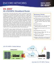
Page 16 <strong>Pro<strong>to</strong>cols</strong> Module, Document 66.2 MultiLink <strong>Point</strong>-<strong>to</strong>-<strong>Point</strong>With the vast amount of data being transmitted from one point <strong>to</strong> another, it is becomingmore common <strong>to</strong> link two sites <strong>to</strong>gether with multiple lines. Multi-link PPP (MLP) allowsseveral physical lines <strong>to</strong> be logically bound <strong>to</strong>gether so that they appear as one line. Thisallows two or more devices at the same site <strong>to</strong> use the additional bandwidth, whileincreasing cost-efficiency.When a unit that supports MLP detects impending congestion on one link, it can dial up asecond connection <strong>to</strong> temporarily add additional capacity. Multiple lines might also allowyou <strong>to</strong> purchase two 56 kbps links rather than one T1 link, so that you can transmit the sameamount of data for less money.Figure 6-4. Sample Network for PPP over ModemHow <strong>to</strong> Configure MLPNote: To successfully route data through the unit, you must complete the IP Routing Table.See Section 1.1, Routing. To use IP routing, you must enter the local IP address. SeeSection 4.2, Identifying the BANDIT in the Network.1 From the Main Menu, select Advanced <strong>Configuration</strong>s.
<strong>Point</strong>-<strong>to</strong>-<strong>Point</strong> Pro<strong>to</strong>col <strong>Configuration</strong> Page 17Main Menu----------1) QuickStart Config Builder2) Typical <strong>Configuration</strong>s3) Advanced <strong>Configuration</strong>s4) ToolsV) View Current Unit StatusF) Cellular Fast ConnectL) Load Fac<strong>to</strong>ry DefaultsP) Load Plug and Play DefaultsW) Write <strong>Configuration</strong>R) Reset UnitX) eXit SessionS) StatisticsY) sYstem AdministrationEnter Choice :❖ The Advanced <strong>Configuration</strong>s Menu is displayed.Advanced <strong>Configuration</strong>s------------------------1) Physical <strong>Configuration</strong>s2) Data <strong>Configuration</strong>s3) Local Address4) Routing5) Global PathsEnter Choice :2 On the Advanced <strong>Configuration</strong>s Menu, select Data <strong>Configuration</strong>s.❖ The Logical Port Pro<strong>to</strong>col Menu is displayed.Logical Port Pro<strong>to</strong>col Attached To Port Interfaces------------------------------------------------------------------------C) Comm/Supervisor Comm/Sup DCEM) <strong>Point</strong>-<strong>to</strong>-<strong>Point</strong> MODEM INTERNALL) EtherNet DHCP Server 192.168.10.1 ETHERNETW) EtherNet DHCP Client 0.0.0.0 ETHERNETS) Frame Relay SERIALB) RDU/IDU Ports...1) Ports 1 <strong>to</strong> 202) Ports 21 <strong>to</strong> 403) Ports 41 <strong>to</strong> 604) Ports 61 <strong>to</strong> 75Enter Port :3 On the Logical Port Pro<strong>to</strong>col Menu, select a port.❖ The port’s Logical Port Attribute Menu is displayed.
Page 18 <strong>Pro<strong>to</strong>cols</strong> Module, Document 6Logical Port Attribute Menu----------------------------1) Pro<strong>to</strong>col : <strong>Point</strong>-<strong>to</strong>-<strong>Point</strong>2) Global Paths3) Undefine Current Logical PortEnter Choice :4 On the Logical Port Attribute Menu, select Undefine Current Logical Port.❖ The Logical Port Attribute Menu is redisplayed, with pro<strong>to</strong>col undefined.Logical Port Attribute Menu----------------------------1) Pro<strong>to</strong>col : <strong>Point</strong>-<strong>to</strong>-<strong>Point</strong>2) Global Paths3) Undefine Current Logical PortEnter Choice :5 Then, on the Logical Port Attribute Menu, select Pro<strong>to</strong>col.❖ The list of pro<strong>to</strong>cols available for the port is displayed.Logical Port Pro<strong>to</strong>col Selection Menu-------------------------------------1) Frame Relay2) <strong>Point</strong>-<strong>to</strong>-<strong>Point</strong> (PPP)3) MultiLink PPP4) X.25+5) ALC6) Bit Sync Encapsulation7) X.42 Spoofing8) Diagnostic Async9) CDCA) Voice/PCM EncapsulationEnter Choice : 3 MultiLink <strong>Point</strong>-<strong>to</strong>-<strong>Point</strong>6 Select MultiLink PPP (Multilink <strong>Point</strong>-<strong>to</strong>-<strong>Point</strong>).❖ The MLP Config Parameters Menu is displayed.MLP Config Parameters : EXPANSION-------------------------------------1) Bundle <strong>Configuration</strong>Enter Choice : 1
<strong>Point</strong>-<strong>to</strong>-<strong>Point</strong> Pro<strong>to</strong>col <strong>Configuration</strong> Page 197 Select Bundle <strong>Configuration</strong>. This option specifies which ports should be combinedwithin this port for multiplexing.❖ The following menu is displayed:Bundle <strong>Configuration</strong> : EXPANSION------------------------------------1) MRRU : 30002) MP Header : MUST3) MemberLink TableEnter Choice :a Select MRRU. This option allows you <strong>to</strong> specify the maximum size of a reassembledpacket (Maximum Receive Reconstructed Unit or MRRU) on a multi-link port. If apacket exceeds the specified size, it is discarded.❖ The following prompt is displayed:Enter Desired MRRU Value :b Enter the desired value and press Enter.c Select MP Header and indicate whether the MP header must be included.MP Header---------1)MUST2)NOT-MUSTEnter Choice :d Select MemberLink Table. This item constructs a table listing the other ports thatshould be included in this multi-linked port. The Multi-link Pro<strong>to</strong>col performs loadbalancing by distributing the packets evenly among the member ports.❖ The following prompt is displayed.Enter Logical Member Port No:8 Type the letter or number of a port that has been configured for PPP.Note: These are ports that you have previously configured for PPP. For example, ifyou have configured the serial port for PPP, you can enter S. Or, if the CSU/DSU port,in an expansion slot, is configured for PPP, you can enter E here.❖ The following prompt is displayed.
Page 20 <strong>Pro<strong>to</strong>cols</strong> Module, Document 6Enter Logical Member Port No:9 Do one of the following:a If you wish <strong>to</strong> add another line <strong>to</strong> the bundle, return <strong>to</strong> Step 8.b If you have added all the lines you wish <strong>to</strong> bundle, press the Escape key.❖ The table is displayed.EntryPortNo1 MODEMAdd, Modify, or Delete an Entry? (Enter A, M, or D):c Press the Escape key <strong>to</strong> return <strong>to</strong> the Main Menu. Then Write (save) the configurationand Reset the BANDIT.Note: When a port configured for PPP is part of a bundle, authentication is ignored.6.3 <strong>Point</strong>-<strong>to</strong>-<strong>Point</strong> Pro<strong>to</strong>col over Frame RelayNote: For most parameters, default values are shown in brackets—for example, [value]. Toaccept a default value, press Enter.To configure PPP over Frame Relay, perform the following procedures:1 Configure a serial port for Frame Relay. See Routing with Frame Relay.2 Build a global path <strong>to</strong> the Frame Relay port. See Defining Global Paths.3 Configure a Logical Port for PPP over Frame Relay.If you want the BANDIT device <strong>to</strong> use Multilink PPP over Frame Relay, do the following:4 Perform Step 1 and Step 2 at least once, so that there is a Frame Relay port <strong>to</strong> carry PPP.5 Perform Step 3 for each PPPoFR line that you wish <strong>to</strong> include in the MultiLink PPPoFRbundle.6 Bundle the configured PPPoFR applications in<strong>to</strong> a Multilink PPPoFR application. SeeMultiLink <strong>Point</strong>-<strong>to</strong>-<strong>Point</strong>.Note: To successfully route data through the BANDIT device, you must complete the IPRouting Table; see Section 1.1, Routing. And, <strong>to</strong> use IP routing, you must configure the localIP address; see Section 4.2, Identifying the BANDIT in the Network.
<strong>Point</strong>-<strong>to</strong>-<strong>Point</strong> Pro<strong>to</strong>col <strong>Configuration</strong> Page 21How <strong>to</strong> Configure PPPoFRNote: This is a long procedure. For specific information, see the followingsubheadings:• Identifying the BANDIT Device• Configuring a Frame Relay Port• Configuring PPP over Frame Relay• Configuring Multilink PPP over Frame Relay• Configuring the IP Interface Table• Configuring the RIP Static Routing Table• Saving the <strong>Configuration</strong>1 Log in<strong>to</strong> the BANDIT.❖ The login message is displayed.**************************************************************** ** WARNING: You are accessing an actively moni<strong>to</strong>red system ** ** Unauthorized access prohibited! ** ** Disconnect IMMEDIATELY if you are not an authorized user ** ****************************************************************❖ Then the login password is requested.Enter Password: ********2 Type the login password and press Enter.Note: Consult your network administra<strong>to</strong>r for passwords. For default passwords, seeDefault Passwords.❖ The welcome message is displayed.WELCOME TO ENCORE PRODUCT -- BANDIT III, ELIOS Version:16631.F307Copyright ENCORE NETWORKS Inc., 2002-2010.❖ Then the Main Menu is displayed.
Page 22 <strong>Pro<strong>to</strong>cols</strong> Module, Document 6Main Menu----------1) QuickStart Config Builder2) Typical <strong>Configuration</strong>s3) Advanced <strong>Configuration</strong>s4) ToolsV) View Current Unit StatusF) Cellular Fast ConnectL) Load Fac<strong>to</strong>ry DefaultsP) Load Plug and Play DefaultsW) Write <strong>Configuration</strong>R) Reset UnitX) eXit SessionS) StatisticsY) sYstem AdministrationEnter Choice :Identifying the BANDIT Device3 On the Main Menu, select Typical <strong>Configuration</strong>s.❖ The Typical <strong>Configuration</strong>s Menu is displayed.Typical <strong>Configuration</strong>s Menu----------------------------1) System <strong>Configuration</strong>2) IP Interfaces3) IP Static Routes4) VPN Profiles5) IP/VPN Policies6) NAT Profiles7) DNS/DHCP Servers8) Configure Firewall9) IP QoS (Quality of Service)A) GPS Geo-FencingL) LAN : EtherNet No DHCP ETHERNETW) WAN : EtherNet No DHCP ETHERNETM) MODEM : <strong>Point</strong>-<strong>to</strong>-<strong>Point</strong> MODEM INTERNALS) SERIAL : Frame Relay SERIALE) EXPANSION : Frame Relay EXPANSION Dual T1/E1B) RDU/IDU Ports...P) More Ports...Enter Choice :4 Select System <strong>Configuration</strong>.❖ The menu <strong>to</strong> Configure System Parameters is displayed.
<strong>Point</strong>-<strong>to</strong>-<strong>Point</strong> Pro<strong>to</strong>col <strong>Configuration</strong> Page 23Configure System Parameters----------------------------1) System IP Address : 0.0.0.02) System Name :Enter Choice :5 On the menu <strong>to</strong> Configure System Parameters, select System IP Address.❖ The following prompt is displayed.Enter Local IP Address (N.N.N.N) :6 Type the BANDIT’s IP address and press Enter.Note: Get all IP addresses from your network administra<strong>to</strong>r.❖ The menu <strong>to</strong> Configure System Parameters is redisplayed, with the BANDIT’s IPaddress.Configure System Parameters----------------------------1) System IP Address : 10.1.1.12) System Name :Enter Choice :7 On the menu <strong>to</strong> Configure System Parameters, select System Name.❖ The following prompt is displayed.Enter Local BANDIT Name (Maximum 15 characters):8 Type a name for the BANDIT and press Enter.Note: The device name must be unique in the network. Get all device names fromyour network administra<strong>to</strong>r.❖ The menu <strong>to</strong> Configure System Parameters is redisplayed, with the BANDIT’s nameabove the menu.
Page 24 <strong>Pro<strong>to</strong>cols</strong> Module, Document 6BANDIT3_PPPConfigure System Parameters----------------------------1) System IP Address : 10.1.1.12) System Name : BANDIT3_PPPEnter Choice :9 Press Escape <strong>to</strong> return <strong>to</strong> the Typical <strong>Configuration</strong>s Menu.BANDIT3_PPPTypical <strong>Configuration</strong>s Menu----------------------------1) System <strong>Configuration</strong>2) IP Interfaces3) IP Static Routes4) VPN Profiles5) IP/VPN Policies6) NAT Profiles7) DNS/DHCP Servers8) Configure Firewall9) IP QoS (Quality of Service)A) GPS Geo-FencingL) LAN : EtherNet No DHCP ETHERNETW) WAN : EtherNet No DHCP ETHERNETM) MODEM : <strong>Point</strong>-<strong>to</strong>-<strong>Point</strong> MODEM INTERNALS) SERIAL : Frame Relay SERIALE) EXPANSION : Frame Relay EXPANSION Dual T1/E1B) RDU/IDU Ports...P) More Ports...Enter Choice :Configuring a Frame Relay Port10 On the Typical <strong>Configuration</strong>s Menu, select a port <strong>to</strong> carry the Frame Relay pro<strong>to</strong>col.Note: In this example, we select the Serial port.❖ The port’s Logical Port Attribute Menu is displayed.BANDIT3_PPPLogical Port Attribute Menu----------------------------1) Pro<strong>to</strong>col : Frame Relay2) Global Paths3) Undefine Current Logical PortEnter Choice :
<strong>Point</strong>-<strong>to</strong>-<strong>Point</strong> Pro<strong>to</strong>col <strong>Configuration</strong> Page 25Note: Because this port’s pro<strong>to</strong>col is Frame Relay, we do not need <strong>to</strong> undefine thelogical port and establish the Frame Relay pro<strong>to</strong>col. We need only <strong>to</strong> review the FrameRelay configuration.11 On the Logical Port Attribute Menu, select Pro<strong>to</strong>col.❖ The Frame Relay Management Parameters Menu is displayed.BANDIT3_PPPFrame Relay Management Parameters : SERIAL-------------------------------------------------1) Type : Synchronous Frame Relay2) Speed : 560003) Pro<strong>to</strong>col : Adaptive Management - User4) Value N1 : 65) Value N2 : 36) Value N3 : 47) Timer T1 : 108) Timer T2 : 159) Priority / CIR Enforcement : DisabledA) High <strong>to</strong> Medium Ratio : 4:1B) Medium <strong>to</strong> Low Ratio : 4:1C) DLCI CIR InformationD) FRF-12 Fragmentation : DisabledEnter Choice :12 If you wish <strong>to</strong> use a different value for a parameter, select that parameter and configureit with the new value.13 For this example, we do not need <strong>to</strong> reconfigure any parameters. Press the Escape key<strong>to</strong> return <strong>to</strong> the Logical Port Attribute Menu.BANDIT3_PPPLogical Port Attribute Menu----------------------------1) Pro<strong>to</strong>col : Frame Relay2) Global Paths3) Undefine Current Logical PortEnter Choice :14 On the Logical Port Attribute Menu, select Global Path, <strong>to</strong> set up a global path <strong>to</strong> thisFrame Relay port.❖ If there is a Global Path Table for this port, it is displayed. Otherwise, the followingprompt is displayed.Empty Global Path TableAdd Global Path Table EntryEnter Path Name (1 <strong>to</strong> 10 Characters): FRAME
Page 26 <strong>Pro<strong>to</strong>cols</strong> Module, Document 615 Type a name for this global path and press Enter. In this example, we type FRAME.Note: Global Path names are case-sensitive. FRAME, Frame, and frame are differentGlobal Path names.❖ A prompt asks for the DLCI for Frame Relay.Enter FR DLCI Number (16-1007) :16 Type the DLCI and press Enter.Note: Get Frame Relay DLCIs from your network administra<strong>to</strong>r.❖ A prompt presents more options for Frame Relay.Any Advanced Features ?(B - Backup Path H - Help)(U - FrameRelay UnicastingN - None) [N] :17 This example does not use advanced features. Press N (for None).❖ A prompt indicates that the record has been added <strong>to</strong> the Global Paths Table.Entry added.❖ Another prompt waits for the next record.To View the entry press ESC or To Add another entryEnter Path Name (1 <strong>to</strong> 10 Characters):18 Press Escape <strong>to</strong> see the Global Paths Table.Entry Path Name PathType Port DLCI----- ---------- -------- ------ -----1 FRAME FR PVC SERIAL 16Add, Modify, or Delete an Entry? (Enter A, M, or D):
<strong>Point</strong>-<strong>to</strong>-<strong>Point</strong> Pro<strong>to</strong>col <strong>Configuration</strong> Page 2719 Press Escape when you have finished reviewing the Global Paths Table.❖ The following prompt is displayed.Global Path Table Handling Complete❖ Then the port’s Logical Port Attribute Menu is redisplayed.BANDIT3_PPPLogical Port Attribute Menu----------------------------1) Pro<strong>to</strong>col : Frame Relay2) Global Paths3) Undefine Current Logical PortEnter Choice :20 Press Escape <strong>to</strong> return <strong>to</strong> the Typical <strong>Configuration</strong>s Menu.BANDIT3_PPPTypical <strong>Configuration</strong>s Menu----------------------------1) System <strong>Configuration</strong>2) IP Interfaces3) IP Static Routes4) VPN Profiles5) IP/VPN Policies6) NAT Profiles7) DNS/DHCP Servers8) Configure Firewall9) IP QoS (Quality of Service)A) GPS Geo-FencingL) LAN : EtherNet No DHCP ETHERNETW) WAN : EtherNet No DHCP ETHERNETM) MODEM : <strong>Point</strong>-<strong>to</strong>-<strong>Point</strong> MODEM INTERNALS) SERIAL : Frame Relay SERIALE) EXPANSION : Frame Relay EXPANSION Dual T1/E1B) RDU/IDU Ports...P) More Ports...Enter Choice :Configuring PPP over Frame Relay21 On the Typical <strong>Configuration</strong>s Menu, select More Ports.❖ The Typical <strong>Configuration</strong>s Menu for Logical Ports is displayed.
Page 28 <strong>Pro<strong>to</strong>cols</strong> Module, Document 6BANDIT3_PPPTypical <strong>Configuration</strong>s Menu----------------------------1) Ports 1 <strong>to</strong> 202) Ports 21 <strong>to</strong> 403) Ports 41 <strong>to</strong> 604) Ports 61 <strong>to</strong> 75Enter Choice :22 On the Typical <strong>Configuration</strong>s Menu for Logical Ports, select a port group—forexample, select Ports 1 <strong>to</strong> 20.❖ The Logical Port Pro<strong>to</strong>col Menu for the selected Logical Ports is displayed.BANDIT3_PPPLogical Port Pro<strong>to</strong>col Mapped To Port Interfaces------------------------------------------------------------------------1) UNDEFINED2) UNDEFINED3) UNDEFINED4) UNDEFINED5) UNDEFINED6) UNDEFINED7) UNDEFINED8) UNDEFINED9) UNDEFINED10) UNDEFINED11) UNDEFINED12) UNDEFINED13) UNDEFINED14) UNDEFINED15) UNDEFINED16) UNDEFINED17) UNDEFINED18) UNDEFINED19) UNDEFINED20) UNDEFINEDEnter Port :23 On the Logical Port Pro<strong>to</strong>col Menu, select a Logical Port <strong>to</strong> carry the Port-<strong>to</strong>-PortPro<strong>to</strong>col. (In this example, we select port 1.)❖ The port’s Logical Port Attribute Menu is displayed.BANDIT3_PPPLogical Port Attribute Menu----------------------------1) Pro<strong>to</strong>col : UNDEFINED2) Global Paths3) Undefine Current Logical PortEnter Choice :
<strong>Point</strong>-<strong>to</strong>-<strong>Point</strong> Pro<strong>to</strong>col <strong>Configuration</strong> Page 2924 On the Logical Port Attribute Menu, select Pro<strong>to</strong>col.❖ The Logical Port Pro<strong>to</strong>col Selection Menu is displayed.BANDIT3_PPPLogical Port Pro<strong>to</strong>col Selection Menu-------------------------------------1) Frame Relay2) PPPoF(PPP over FR)3) MultiLink PPP4) X.25+5) ALC6) Asynchronous Encapsulation7) Telnet Terminal8) XXX PAD9) X.42 SpoofingA) Diagnostic AsyncB) CDCC) Voice/PCM EncapsulationEnter Choice :25 On the Logical Port Pro<strong>to</strong>col Selection Menu, select PPPoF (PPP over FR).❖ The PPP Config Parameters Menu is displayed.BANDIT3_PPPPPP Config Parameters : Port 1-------------------------------------1) Type : PPP over Frame Relay(PPPOF)2) Frame Relay Global Path Name : 3) IP Address <strong>Configuration</strong>4) LQM Moni<strong>to</strong>ring : Disable5) LQM Percentage : 706) LQM Timer : 1207) MRU : 15008) PPP Authentication <strong>Configuration</strong>Enter Choice :26 On the PPP Config Parameters Menu, select Frame Relay Global Path Name.❖ A prompt is displayed for the global path <strong>to</strong> a Frame Relay port.Enter Path Name (1 <strong>to</strong> 10 Characters):27 Type the global path name for a configured Frame Relay port, and press Enter. (In thisexample, the global path name is FRAME.)❖ The PPP Config Parameters Menu is redisplayed, showing the global path name.
Page 30 <strong>Pro<strong>to</strong>cols</strong> Module, Document 6BANDIT3_PPPPPP Config Parameters : Port 1-------------------------------------1) Type : PPP over Frame Relay(PPPOF)2) Frame Relay Global Path Name : FRAME3) IP Address <strong>Configuration</strong>4) LQM Moni<strong>to</strong>ring : Disable5) LQM Percentage : 706) LQM Timer : 1207) MRU : 15008) PPP Authentication <strong>Configuration</strong>Enter Choice : 328 On the PPP Config Parameters Menu, select IP Address <strong>Configuration</strong>.❖ The PPP Interface IP Address Menu is displayed.BANDIT3_PPPPPP Interface IP Address : Port 1----------------------------------------1) Negotiation Method : Get IP Addr Dynamically2) User Specified IP Address : N/AEnter Choice : 129 On the PPP Interface IP Address Menu, select Negotiation Method.❖ The Negotiation Method Menu is displayed.Negotiation Method-------------------1) Get IP Addr Dynamically2) Negotiate User Specified IP Addr3) Do Not Negotiate IP AddrEnter Choice :30 On the Negotiation Method Menu, select Negotiate User Specified IP Addr.❖ The PPP Interface IP Address Menu is displayed again. Note that the User SpecifiedIP Address now has the value 0.0.0.0. We need <strong>to</strong> specify the IP address that will beused.
<strong>Point</strong>-<strong>to</strong>-<strong>Point</strong> Pro<strong>to</strong>col <strong>Configuration</strong> Page 31BANDIT3_PPPPPP Interface IP Address : Port 1----------------------------------------1) Negotiation Method : User Specified IP Address2) User Specified IP Address : 0.0.0.0Enter Choice : 231 On the redisplayed PPP Interface IP Address Menu, select User Specified IP Address.❖ The following prompt is displayed.User Specified IP Address (N.N.N.N) :32 Type the BANDIT’s IP address and press Enter.❖ The PPP Interface IP Address Menu is redisplayed, with the specified IP address.BANDIT3_PPPPPP Interface IP Address : Port 1----------------------------------------1) Negotiation Method : User Specified IP Address2) User Specified IP Address : 10.1.1.1Enter Choice :33 Press Escape until you return <strong>to</strong> the PPP Config Parameters Menu.BANDIT3_PPPPPP Config Parameters : Port 1-------------------------------------1) Type : PPP over Frame Relay(PPPOF)2) Frame Relay Global Path Name : FRAME3) IP Address <strong>Configuration</strong>4) LQM Moni<strong>to</strong>ring : Disable5) LQM Percentage : 706) LQM Timer : 1207) MRU : 15008) PPP Authentication <strong>Configuration</strong>Enter Choice : 334 To configure other items on the PPP Config Parameters Menu, see Step 10 (on page 11)through Step 14 in How <strong>to</strong> Configure PPP.35 After you have configured PPP for the BANDIT device, press Escape until you return<strong>to</strong> the Logical Port Pro<strong>to</strong>col Menu.
Page 32 <strong>Pro<strong>to</strong>cols</strong> Module, Document 6BANDIT3_PPPLogical Port Pro<strong>to</strong>col Mapped To Port Interfaces------------------------------------------------------------------------1) PPPoFR SERIAL2) UNDEFINED3) UNDEFINED4) UNDEFINED5) UNDEFINED6) UNDEFINED7) UNDEFINED8) UNDEFINED9) UNDEFINED10) UNDEFINED11) UNDEFINED12) UNDEFINED13) UNDEFINED14) UNDEFINED15) UNDEFINED16) UNDEFINED17) UNDEFINED18) UNDEFINED19) UNDEFINED20) UNDEFINEDEnter Port : 1036 Do one of the following:a If you wish <strong>to</strong> configure another Logical Port for PPP, select another port on the LogicalPort Pro<strong>to</strong>col Menu, and perform, Step 23 through Step 35 for that port.b When you have configured PPP as required for the BANDIT device, continue <strong>to</strong> Step 37.Configuring Multilink PPP over Frame RelayNote: How <strong>to</strong> Configure MLP (on page 16) presents a full procedure for Multilink PPP.37 On the Logical Port Pro<strong>to</strong>col Menu, select a port for Multilink PPP over Frame Relay.(In this example, we select Logical Port 10 <strong>to</strong> use Multilink PPP over Frame Relay.)❖ The selected port’s Logical Port Attribute Menu is displayed.BANDIT3_PPPLogical Port Attribute Menu----------------------------1) Pro<strong>to</strong>col : UNDEFINED2) Global Paths3) Undefine Current Logical PortEnter Choice : 138 On the Logical Port Attribute Menu, select Pro<strong>to</strong>col.❖ The port’s Logical Port Pro<strong>to</strong>col Selection Menu is displayed.
<strong>Point</strong>-<strong>to</strong>-<strong>Point</strong> Pro<strong>to</strong>col <strong>Configuration</strong> Page 33BANDIT3_PPPLogical Port Pro<strong>to</strong>col Selection Menu-------------------------------------1) Frame Relay2) PPPoF(PPP over FR)3) MultiLink PPP4) X.25+5) ALC6) Asynchronous Encapsulation7) Telnet Terminal8) XXX PAD9) X.42 SpoofingA) Diagnostic AsyncB) CDCC) Voice/PCM EncapsulationEnter Choice :39 On the Logical Port Pro<strong>to</strong>col Selection Menu, select Multilink PPP.❖ The MLP Config Parameters Menu is displayed.BANDIT3_PPPMLP Config Parameters : Port 10-------------------------------------1) Bundle <strong>Configuration</strong>Enter Choice : 140 On the MLP Config Parameters Menu, select Bundle <strong>Configuration</strong>.❖ The Bundle <strong>Configuration</strong> Menu is displayed.BANDIT3_PPPBundle <strong>Configuration</strong> : Port 10------------------------------------1) MRRU : 30002) MP Header : MUST3) MemberLink TableEnter Choice : 341 On the Bundle <strong>Configuration</strong> Menu, select MemberLink Table.❖ If this port does not yet have bundled ports, a prompt indicates that its table is empty.Empty Member Link Table
Page 34 <strong>Pro<strong>to</strong>cols</strong> Module, Document 6❖ Another prompt asks for the first Logical Port <strong>to</strong> bundle in<strong>to</strong> this multilink PPP port.Add Member Link EntryEnter Logical Member Port No:42 Type the Logical Port <strong>to</strong> add <strong>to</strong> the multilink PPP bundle, and press Enter.!Caution: At this prompt, add the value 20 <strong>to</strong> the number of the Logical Port you areentering. For example, for Logical Port 1, type 21. For Logical Port 54, type 74.❖ A prompt indicates that the port has been added <strong>to</strong> the bundle, and requests thenumber of the next port <strong>to</strong> add.Entry AddedEnter Logical Member Port No:43 Do one of the following:a If you wish <strong>to</strong> add another Logical Port (already configured for PPP), repeat Step 42.Note: For example, if you have already configured Logical Port 7 for PPP, you can addport 7 <strong>to</strong> the Multilink PPP bundle.b If you have finished adding Logical Ports <strong>to</strong> this Multilink PPP, press Escape.❖ A table is displayed, showing the Logical Ports bundled in<strong>to</strong> this Multilink PPP.Note: As anticipated, table entry 1 (for which we typed 21 in Step 42) displays LogicalPort 1.Entry PortNo1 Port 12 Port 7Add, Modify, or Delete an Entry? (Enter A, M, or D):44 When you have finished bundling the multilink PPP, press Escape.❖ A prompt indicates that the table is complete.MLP Member Table Handling Complete
<strong>Point</strong>-<strong>to</strong>-<strong>Point</strong> Pro<strong>to</strong>col <strong>Configuration</strong> Page 35❖ Then the Bundle <strong>Configuration</strong> Menu is redisplayed.BANDIT3_PPPBundle <strong>Configuration</strong> : Port 10------------------------------------1) MRRU : 30002) MP Header : MUST3) MemberLink TableEnter Choice :45 Press Escape <strong>to</strong> return <strong>to</strong> the MLP Config Parameters Menu.BANDIT3_PPP: Port 10-------------------------------------1) Bundle <strong>Configuration</strong>Enter Choice :46 Press Escape <strong>to</strong> return <strong>to</strong> the Logical Port Attribute Menu.BANDIT3_PPPLogical Port Attribute Menu----------------------------1) Pro<strong>to</strong>col : MultiLink <strong>Point</strong>-<strong>to</strong>-<strong>Point</strong>2) Global Paths3) Undefine Current Logical PortEnter Choice :47 On the Logical Port Attribute Menu, select Global Paths.❖ Because this port does not yet have a global path, its table is empty.Empty Global Path TableAdd Global Path Table Entry❖ A prompt requests global path name.Enter Path Name (1 <strong>to</strong> 10 Characters): MLPPP
Page 36 <strong>Pro<strong>to</strong>cols</strong> Module, Document 648 Type the global path name and press Enter.Note: This example uses the global path name MLPPP for this port.❖ A prompt indicates that the name has been accepted.Entry added.❖ Then a prompt asks for another entry.To View the entry press ESC or To Add another entryEnter Path Name (1 <strong>to</strong> 10 Characters):49 Press Escape <strong>to</strong> view this Global Paths Table.Entry Path Name PathType Port----- ---------- -------- ----1 MLPPP PORT TYPE Port 10Add, Modify, or Delete an Entry? (Enter A, M, or D):50 When you have finished reviewing the Global Paths Table for this port, press Escape.❖ A prompt indicates that the table is complete.Global Path Table Handling Complete❖ Then the port’s Logical Port Attribute Menu is redisplayed.BANDIT3_PPPLogical Port Attribute Menu----------------------------1) Pro<strong>to</strong>col : MultiLink <strong>Point</strong>-<strong>to</strong>-<strong>Point</strong>2) Global Paths3) Undefine Current Logical PortEnter Choice :51 Press Escape <strong>to</strong> return <strong>to</strong> the Logical Port Pro<strong>to</strong>col Menu.
<strong>Point</strong>-<strong>to</strong>-<strong>Point</strong> Pro<strong>to</strong>col <strong>Configuration</strong> Page 37BANDIT3_PPPLogical Port Pro<strong>to</strong>col Mapped To Port Interfaces------------------------------------------------------------------------1) PPPoFR SERIAL2) UNDEFINED3) UNDEFINED4) UNDEFINED5) UNDEFINED6) UNDEFINED7) UNDEFINED8) UNDEFINED9) UNDEFINED10) MultiLink PPP11) UNDEFINED12) UNDEFINED13) UNDEFINED14) UNDEFINED15) UNDEFINED16) UNDEFINED17) UNDEFINED18) UNDEFINED19) UNDEFINED20) UNDEFINEDEnter Port :52 Press Escape <strong>to</strong> return <strong>to</strong> the Typical <strong>Configuration</strong>s Menu for Logical Ports.BANDIT3_PPPTypical <strong>Configuration</strong>s Menu----------------------------1) Ports 1 <strong>to</strong> 202) Ports 21 <strong>to</strong> 403) Ports 41 <strong>to</strong> 604) Ports 61 <strong>to</strong> 75Enter Choice :53 Press Escape <strong>to</strong> return <strong>to</strong> the Typical <strong>Configuration</strong>s Menu.
Page 38 <strong>Pro<strong>to</strong>cols</strong> Module, Document 6BANDIT3_PPPTypical <strong>Configuration</strong>s Menu----------------------------1) System <strong>Configuration</strong>2) IP Interfaces3) IP Static Routes4) VPN Profiles5) IP/VPN Policies6) NAT Profiles7) DNS/DHCP Servers8) Configure Firewall9) IP QoS (Quality of Service)A) GPS Geo-FencingL) LAN : EtherNet No DHCP ETHERNETW) WAN : EtherNet No DHCP ETHERNETM) MODEM : <strong>Point</strong>-<strong>to</strong>-<strong>Point</strong> MODEM INTERNALS) SERIAL : Frame Relay SERIALE) EXPANSION : Frame Relay EXPANSION Dual T1/E1B) RDU/IDU Ports...P) More Ports...Enter Choice :Configuring the IP Interface Table54 On the Typical <strong>Configuration</strong>s Menu, select IP Interfaces.❖ If there are no records in the IP Interface Table, a message indicates that the table isempty.Empty IP Interface Table❖ Another message requests the IP address for the first record.Add IP Interface Table EntryEnter Interface IP Address (N.N.N.N or 0.0.0.0 = Unnumbered) :55 Type the IP address and press Enter.Note: The first IP address will be the IP address for this BANDIT device. In thisexample, that IP address is 10.1.1.1.❖ A prompt asks for the subnet mask.Enter Interface Subnet Mask (N.N.N.N or 255.255.255.0) : 255.255.255.0
<strong>Point</strong>-<strong>to</strong>-<strong>Point</strong> Pro<strong>to</strong>col <strong>Configuration</strong> Page 3956 If necessary, modify the subnet mask. Then press Enter.❖ A prompt requests the global path name for the record.Enter Path Name (1 <strong>to</strong> 10 Characters):57 Type the global path name that you entered (MLPPP, in Step 48) for the Multilink PPP,and press Enter.❖ A prompt asks for the next hop.Enter Next Hop Router Address. for Broadcast (N.N.N.N) :58 Type the IP address of the remote device (the destination), and press Enter.Note: In this example, the remote device uses the IP address 10.1.1.2.❖ A prompt requests the RIP mode. (The bracketed item at the end of the promptindicates the current mode.)Enter RIP Mode ((1) On) ((2) Send) ((3) Listen) ((4) Off), [4]:59 If necessary, change the RIP mode. Press Enter.❖ A prompt indicates the NAT configuration, if any, <strong>to</strong> use for this connection.Enter NAT <strong>Configuration</strong> Number ( 0 = None ), [None] :60 If necessary, change the NAT configuration number. (The default shown here is None.)Press Enter.❖ A prompt requests a backup IP address (for use by the BANDIT’s modem).Note: For most parameters, default values are shown in brackets—for example,[value]. To accept a default value, press Enter.For dynamic IP addresses, please use 0.0.0.1 = modem,0.0.0.2 = modem over SERIAL or 0.0.0.3 = modem over EXPANSION.Enter BackUp Interface IP Address, [None]:
Page 40 <strong>Pro<strong>to</strong>cols</strong> Module, Document 661 Type a backup IP address (or leave the item blank) and press Enter.❖ A prompt requests size of the maximum transmission unit (or maximum transferunit, MTU).Enter the MTU (256 <strong>to</strong> 1500)[1500] :62 Type the size of the MTU (in bytes) and press Enter.❖ Additional parameters request configuration. Type each value (or leave the valueblank) as appropriate, and press Enter.Enable Dynamic MTU adjustment based upon priorities?(Y/N), [N]:Enter remote ping address(N.N.N.N, 0.0.0.0 = NONE),[NONE]:Enable VRRP(Yes/No),[N]?:❖ When all the parameter values have been established, a message indicates that therecord has been added <strong>to</strong> the table. Then another messages requests information forthe next record.Entry AddedEnter Interface IP Address (N.N.N.N or 0.0.0.0 = Unnumbered) :63 Do one of the following:a If you need <strong>to</strong> add another record <strong>to</strong> the IP Interface Table, repeat Step 55 throughStep 62.b If there are no more records for the table, press Escape.❖ The IP Interface Table is displayed.
<strong>Point</strong>-<strong>to</strong>-<strong>Point</strong> Pro<strong>to</strong>col <strong>Configuration</strong> Page 41Entry IP Address Net Mask Gpt Name Next Router Mode MTU---- --------------- -------------- ------------ -------------- ------ ----1 10.1.1.1 255.255.255.0 MLPPP 10.1.1.2 Off 1500Add, Modify, or Delete an Entry? (Enter A, M, or D):64 When you have finished reviewing the IP Interface Table, press Escape.❖ A prompt indicates that the table is complete.IP interface Table Handling Complete❖ Then the Typical <strong>Configuration</strong>s Menu is redisplayed.BANDIT3_PPPTypical <strong>Configuration</strong>s Menu----------------------------1) System <strong>Configuration</strong>2) IP Interfaces3) IP Static Routes4) VPN Profiles5) IP/VPN Policies6) NAT Profiles7) DNS/DHCP Servers8) Configure Firewall9) IP QoS (Quality of Service)A) GPS Geo-FencingL) LAN : EtherNet No DHCP ETHERNETW) WAN : EtherNet No DHCP ETHERNETM) MODEM : <strong>Point</strong>-<strong>to</strong>-<strong>Point</strong> MODEM INTERNALS) SERIAL : Frame Relay SERIALE) EXPANSION : Frame Relay EXPANSION Dual T1/E1B) RDU/IDU Ports...P) More Ports...Enter Choice : 3Configuring the RIP Static Routing Table65 On the Typical <strong>Configuration</strong>s Menu, select IP Static Routes.❖ If the RIP Static Routing Table has no entries, the following message is displayed.Empty RIP Static Routing Table❖ Then another message asks for the first entry in the table.
Page 42 <strong>Pro<strong>to</strong>cols</strong> Module, Document 6Add RIP Static Table EntryEnter Destination IP Address / Network (N.N.N.N) :66 Press Enter <strong>to</strong> accept the default IP address 0.0.0.0.❖ A prompt requests the subnet mask.Enter Subnet Mask (N.N.N.N) :67 Press Enter <strong>to</strong> accept the default IP address 0.0.0.0.❖ A prompt requests the next hop’s IP address.Enter Next Hop Router Address (N.N.N.N or 0.0.0.0 = Unnumbered) : 10.1.1.268 Type the IP address of the remote router (the destination address), and press Enter.❖ A prompt requests the number of hops <strong>to</strong> the destination.Enter Number of Hops <strong>to</strong> destination : 2❖ A message indicates that the record has been added <strong>to</strong> the table. Then information forthe next record is requested.Entry AddedEnter Destination IP Address / Network (N.N.N.N) :Do one of the following:a If there are more records for the table, perform Step 66 through Step 68.b If there are no more records for the table, press Escape.❖ The RIP Static Table is displayed.
<strong>Point</strong>-<strong>to</strong>-<strong>Point</strong> Pro<strong>to</strong>col <strong>Configuration</strong> Page 43Entry IP Address Net Mask Next Router Path Name Hops1 0.0.0.0 0.0.0.0 10.1.1.2 n/a 2Add, Modify, or Delete an Entry? (Enter A, M, or D):69 When you have finished reviewing the table, press Escape.❖ The table completion message is displayed.RIP Static Table Handling Complete❖ Then the Typical <strong>Configuration</strong>s Menu is redisplayed.BANDIT3_PPPTypical <strong>Configuration</strong>s Menu----------------------------1) System <strong>Configuration</strong>2) IP Interfaces3) IP Static Routes4) VPN Profiles5) IP/VPN Policies6) NAT Profiles7) DNS/DHCP Servers8) Configure Firewall9) IP QoS (Quality of Service)A) GPS Geo-FencingL) LAN : EtherNet No DHCP ETHERNETW) WAN : EtherNet No DHCP ETHERNETM) MODEM : <strong>Point</strong>-<strong>to</strong>-<strong>Point</strong> MODEM INTERNALS) SERIAL : Frame Relay SERIALE) EXPANSION : Frame Relay EXPANSION Dual T1/E1B) RDU/IDU Ports...P) More Ports...Enter Choice :70 Press Escape until you reach the Main Menu.
Page 44 <strong>Pro<strong>to</strong>cols</strong> Module, Document 6BANDIT3_PPPMain Menu----------1) QuickStart Config Builder2) Typical <strong>Configuration</strong>s3) Advanced <strong>Configuration</strong>s4) ToolsV) View Current Unit StatusF) Cellular Fast ConnectL) Load Fac<strong>to</strong>ry DefaultsP) Load Plug and Play DefaultsW) Write <strong>Configuration</strong>R) Reset UnitX) eXit SessionS) StatisticsY) sYstem AdministrationEnter Choice : RSaving the <strong>Configuration</strong>71 On the Main Menu, select Reset Unit.❖ Prompts request continuation and passwords.72 Continue with the reset, and enter passwords as requested.Note: Get passwords from your network administra<strong>to</strong>r. For default passwords, seeDefault Passwords.❖ The configuration is saved, and the BANDIT device restarts. It is now reset <strong>to</strong> use thenew configuration.