BANDIT II? Hardware Description - Encore Networks
BANDIT II? Hardware Description - Encore Networks
BANDIT II? Hardware Description - Encore Networks
You also want an ePaper? Increase the reach of your titles
YUMPU automatically turns print PDFs into web optimized ePapers that Google loves.
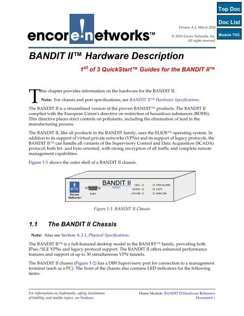
Page 2 <strong>BANDIT</strong> <strong>II</strong> <strong>Hardware</strong> Reference Module, Document 1• State of the cellular wireless port• State of the DB25 serial port• State of the LAN port• Power and alarm states• Supervisory DB9 port status• State of the WAN portThe <strong>BANDIT</strong> <strong>II</strong> can hold one internal wireless card for CDMA, EVDO CDMA, HSDPA,GPRS GSM, or EDGE GSM wireless networks. The wireless card for the <strong>BANDIT</strong> <strong>II</strong> includesan external antenna.Figure 1-2. <strong>BANDIT</strong> <strong>II</strong> Chassis, Front PanelThe <strong>BANDIT</strong> <strong>II</strong> can accept 12, 24, or 48 volts DC from a DC power source, or it can accept+5 volts DC input at 2 amps from its 110/220 volts AC power supply.Figure 1-3 through Figure 1-6 show the backs of the <strong>BANDIT</strong> <strong>II</strong> chassis models.Figure 1-3. <strong>BANDIT</strong> <strong>II</strong> Chassis, Rear Panel,for Connection to 110/220V AC Power SupplyFigure 1-4. <strong>BANDIT</strong> <strong>II</strong> Chassis, Rear Panel,for Connection to 12V DC Power Source
<strong>BANDIT</strong> <strong>II</strong> <strong>Hardware</strong> <strong>Description</strong> Page 3Figure 1-5. <strong>BANDIT</strong> <strong>II</strong> Chassis, Rear Panel,for Connection to 24V DC Power SourceFigure 1-6. <strong>BANDIT</strong> <strong>II</strong> Chassis, Rear Panel,for Connection to 48V DC Power SourceThe following items are on the back of the <strong>BANDIT</strong> <strong>II</strong> chassis:• A port for an antenna for the cellular wireless card, for connection to a wireless network• A port for 12, 24, or 48 volts DC power source input or a port for a 110/220 volts ACpower supply, converting power input to +5 volts DC at 2 amps• A DB25 serial port• A WAN port, typically used as the network uplink to the host• A LAN port• An earth ground connection bolt• A port (not currently used) for future use of a GPS antenna or a second cellular antennaNote: Also see <strong>BANDIT</strong> <strong>II</strong> <strong>Hardware</strong> Specifications.Warning: Always follow safety procedures when working with electrical equipment.See Basic Safety Guidelines.1.1.1 ThroughputThe <strong>BANDIT</strong> <strong>II</strong> chassis has the following system throughput:• LAN to WAN, without encryption: 9,000 packets/second, with incoming and outgoingtraffic at 64 bytes/packet• LAN to WAN, with encryption and decryption: 1,800 packets/second, with incomingtraffic at 50 bytes/packet and outgoing traffic at 100 bytes/packet
<strong>BANDIT</strong> <strong>II</strong> <strong>Hardware</strong> <strong>Description</strong> Page 51.1.4.1.2 The LAN Ethernet PortTable 1-2 shows the interface options for the LAN port.Table 1-2. LAN Port Interface OptionsStandard• <strong>BANDIT</strong> <strong>II</strong>: 10/100-Base-T, with an RJ45 connectorThe LAN Port has the following IP features:• Static routing• Standard RIP V1, V2 routing• Prioritization on Layers 2 and 3• DiffServ marking and classification for end-to-end prioritization• IP Quality of Service• Dynamic bandwidth allocation• 802.1q VLAN tagging• VRRP (RFC 3768)• Fragmentation and reassembly (MTU) LAN• DHCP server, client, relay; Bootp• SNMP, MIB <strong>II</strong>• ARP; Proxy ARP• Routing over VPN tunnels• Dynamic split tunneling1.1.4.2 Serial PortThe <strong>BANDIT</strong> <strong>II</strong> uses a DB25 serial port.Table 1-3 lists the <strong>BANDIT</strong> <strong>II</strong>’s DB25 serial port interface options. Table 1-4 lists the<strong>BANDIT</strong> <strong>II</strong>’s DB25 serial port protocol options. For the <strong>BANDIT</strong> <strong>II</strong>’s DB25 serial port pinconfiguration, see Table A-3. Use the <strong>BANDIT</strong> <strong>II</strong> software to set the DB25 serial port as DCEor DTE.Table 1-3. <strong>BANDIT</strong> <strong>II</strong> DB25 Serial Port Interface OptionsStandard• Serial:- RS-232 (256 kbps sync, 230 kbps async)
Page 6 <strong>BANDIT</strong> <strong>II</strong> <strong>Hardware</strong> Reference Module, Document 1Table 1-4. Serial Port ProtocolsProtocolFeatures SupportedFrame Relay•Link Management- LMI, CCITT, Q.933 Annex A;- ANSI T1.617 Annex D• IP over Frame Relay• CIR Enforcement• Fragmentation FRF12• Fast Connection• Prioritization•Unicasting•MulticastingPPP, Multilink PPP •Sync PPP•Async PPP• MLPPP•PAP•CHAP•IP over PPPIP• All standard IP featuresX.25 • All standard X.25 features1.1.4.3 Wireless PortThe <strong>BANDIT</strong> <strong>II</strong> has one internal wireless port. The <strong>BANDIT</strong> <strong>II</strong> can use a CDMA, EVDO,HSDPA, GSM GPRS, or GSM EDGE wireless card. For more information, see Wireless Cardsfor <strong>BANDIT</strong> Products.1.2 Status LEDsLight-emitting diodes (LEDs) on the front of the <strong>BANDIT</strong> <strong>II</strong> indicate the status ofconnections. The following sections describe the LEDs.1.2.1 General StatusThe following general rules apply to the <strong>BANDIT</strong> products’ LEDs:• A lit green Power LED indicates that the unit is being supplied with power.• A flashing Alarm LED indicates that the <strong>BANDIT</strong> has detected an alarm, or that thesystem needs attention, or that power to the system has failed.• A lit green Link LED indicates that there is a connection to another device, including anEthernet hub or switch.Table 1-5 describes the <strong>BANDIT</strong> <strong>II</strong>’s LEDs.
<strong>BANDIT</strong> <strong>II</strong> <strong>Hardware</strong> <strong>Description</strong> Page 7Table 1-5. <strong>BANDIT</strong> <strong>II</strong> LEDsLED Color <strong>Description</strong>Cellular port Green Connection has been made to wireless carrier.OffThere is no connection to wireless carrier.Serial port Green Connection to device has been made.OffThere is no connection to device.LAN port Green Connection to LAN has been made.OffThere is no connection to LAN.Power/Alarm Green Unit is receiving power.OffGreen blinkingUnit is not receiving power.A port has an alarm, or the system needs attention,or power to the system has failed.Supervisory port Green Connection has been made to management terminal(or to carrier, if the port is used for data).OffThere is no connection.WAN port Green Connection to WAN gateway has been made.OffConnection to WAN gateway has failed.1.2.2 Protocol StatusIn addition to indicating general status, each port’s Activity LED indicates conditions for theprotocol configured on that port. Table 1-6 describes the LEDs for protocols the <strong>BANDIT</strong>supports.Table 1-6. Protocol LED Definitions (Sheet 1 of 2)ProtocolFrame RelayAsync EncapsulationBit Sync EncapsulationAsync/Sync PPPSLIPSDLC Emulation—Terminal 1SDLC Emulation—Host 1SDLC RoutingAnnex GByte Sync EncapsulationGreen Activity LEDIf a Frame Relay Management protocol connection is up, theLED lights after 15–20 seconds. (If there is no connection, theActivity LED remains unlit.)Characters, bidirectional TD/RDFrames in either directionFrames to/from portFrames to/from portSending or receiving dataThe host has a transport layer connection with a terminal listedin the device table.Frames to/from portGood frames are passing through.Good frames are passing through.


