investigation of a prototype industrial gas turbine combustor using ...
investigation of a prototype industrial gas turbine combustor using ...
investigation of a prototype industrial gas turbine combustor using ...

You also want an ePaper? Increase the reach of your titles
YUMPU automatically turns print PDFs into web optimized ePapers that Google loves.
2. Gas Turbine Combustor<br />
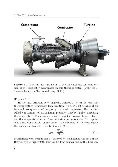
Figure 2.1: The SIT <strong>gas</strong> <strong>turbine</strong>, SGT-750, in which the full-scale version<br />
<strong>of</strong> the <strong>combustor</strong> investigated in this thesis operates. (Courtesy <strong>of</strong><br />
Siemens Industrial Turbomachinery [SIT].)<br />
(Figure 2.2).<br />
In the ideal Brayton cycle diagram, Figure 2.2, it can be seen that<br />
the temperature is increased from position 1 to position 2 because <strong>of</strong> the<br />
isentropic compression <strong>of</strong> the <strong>gas</strong> by the ideal compressor. Heat is then<br />
added via combustion at constant pressure, thereby further increasing<br />
the temperature. The expander then reduces the pressure from P 2 to P 1<br />
and the temperature drops. The area inside the cycle in the T-S diagram<br />
equals the work output <strong>of</strong> the cycle. The efficiency <strong>of</strong> the cycle equals<br />
the work done divided by the heat input (2.1).<br />
η GT = W out<br />
Q in<br />
, (2.1)<br />
Maximizing work output can be achieved by maximizing the area <strong>of</strong> the<br />
Brayton cycle (Figure 2.2). This can be done by maximizing the difference<br />
8