investigation of a prototype industrial gas turbine combustor using ...
investigation of a prototype industrial gas turbine combustor using ...
investigation of a prototype industrial gas turbine combustor using ...

Create successful ePaper yourself
Turn your PDF publications into a flip-book with our unique Google optimized e-Paper software.
3. Experimental setups<br />
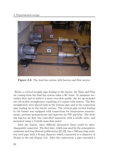
Figure 3.2: The dual fan system with heaters and flow meters.<br />
Before a vertical straight pipe leading to the burner, the Main and Pilot<br />
air coming from the dual fan system takes a 90° bend. To minimize secondary<br />
flow and to achieve a more even flow pr<strong>of</strong>ile, the set up included<br />
two 10 cm flow straighteners consisting <strong>of</strong> a square tube matrix. The flow<br />
straighteners were placed both in the bottom pipe and in the connection<br />
pipe leading up to the burner section. The vertical pipe section leading<br />
to the burner was equipped with connections for temperature measurements,<br />
pressure measurements and injectors for PIV particles. The seeding<br />
injector air flow was controlled separately with a needle valve, and<br />
measured <strong>using</strong> a Coriolis mass flow meter.<br />
After the burner, three different alternative liners could be interchangeably<br />
connected. The first liner, which was used for the atmospheric<br />
emissions and lean blowout publications [21,22], was a 700 mm long stainless<br />
steel pipe with a 85 mm diameter which contracted to a diameter <strong>of</strong><br />
50 mm at the end (Figure 3.3). After the contraction, a pipe extended a<br />
20