investigation of a prototype industrial gas turbine combustor using ...
investigation of a prototype industrial gas turbine combustor using ...
investigation of a prototype industrial gas turbine combustor using ...

Create successful ePaper yourself
Turn your PDF publications into a flip-book with our unique Google optimized e-Paper software.
3. Experimental setups<br />
3.4 The pressurized full burner setup<br />
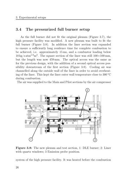
As the full burner did not fit the original plenum (Figure 3.7), the<br />
high pressure facility was modified. A new plenum was built to fit the<br />
full burner (Figure 3.8). In addition the liner section was expanded<br />
to ensure a sufficiently long residence time for complete combustion to<br />
be achieved, i.e. approximately 15 ms, and a <strong>combustor</strong> loading below<br />
10 kg/s atm 1.8 m 3 . The square section <strong>of</strong> the liner was still 100×100 mm,<br />
but the length was now 459 mm. The optical access was the same as<br />
for the previous design, with the addition <strong>of</strong> a second optical access possibility<br />
downstream <strong>of</strong> the first section (Figure 3.8). Cooling air was<br />
channelled along the outside wall <strong>of</strong> the liner in order to avoid overheating<br />
<strong>of</strong> the liner. This kept the liner outer wall temperature close to 300 ◦ C<br />
during combustion.<br />
The air was supplied to the Main and Pilot sections by the air compressor<br />
Figure 3.8: The new plenum and test section, 1: DLE burner; 2: Liner<br />
with quartz windows; 3 Emission probe position.<br />
system <strong>of</strong> the high pressure facility. It was heated before the combustion<br />
26