Plastiline™ - Humes
Plastiline™ - Humes
Plastiline™ - Humes

You also want an ePaper? Increase the reach of your titles
YUMPU automatically turns print PDFs into web optimized ePapers that Google loves.
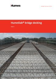
Plastiline <br />
BUILD ON OUR EXPERTISE
CONTENTS<br />
Introduction......................................................................3<br />
Summary of principal properties .....................................5<br />
Resistance to aggressive agents.......................................5<br />
Utilisation.........................................................................6<br />
1 Principal applications .............................................6<br />
2 Degree of lining required.......................................6<br />
3 Pipe sizes and classes.............................................7<br />
4 Fittings ..................................................................7<br />
5 Protection for concrete cast insitu..........................7<br />
6 Plastiline project applications .............................8<br />
Specifications ...................................................................9<br />
1 Composition .........................................................9<br />
2 Manufacture.........................................................9<br />
3 Dimensions ...........................................................9<br />
4 Chemical properties ..............................................9<br />
5 Physical properties ................................................9<br />
6 Incorporation in spun concrete pipes ..................10<br />
7 Incorporation in vertically cast pipes ...................10<br />
8 Laying and jointing .............................................11<br />
9 Incorporation of keyed Plastiline<br />
in cast insitu concrete structures..........................13<br />
10 Methods of jointing.............................................15<br />
11 Testing.................................................................17<br />
12 Repairs ................................................................18<br />
13 Handling - storage - laying..................................18<br />
14 Periodical inspections...........................................19<br />
2
INTRODUCTION<br />
1 The material and its function<br />
Plastiline is a plasticised PVC sheet specially designed to<br />
be embedded in concrete as a surface protection. Shaped<br />
keys provide a mechanical lock with the body of the<br />
concrete. Welding strips and other accessories of the same<br />
formulation and quality as the sheet are readily available.<br />
The prime function of Plastiline is the protection of<br />
concrete against hydrogen sulfide (H 2 S) attack. It is<br />
equally effective against a wide range of acids, alkalis<br />
and aggressive salt solutions.<br />
Plastiline offers complete protection and is suitable for<br />
applications which include sewers, treatment works,<br />
industrial waste lines, storage tanks - in fact, any concrete<br />
structure where aggressive agents are encountered.<br />
Synthetic PVCs of high molar mass have proven<br />
outstanding resistance to aggressive agencies, both in<br />
laboratory tests and under exacting service conditions.<br />
The use of a continuous PVC liner to protect sewers and<br />
sewerage structures is now backed by nearly 40 years of<br />
service experience, with installations in Australia, Saudi<br />
Arabia, Singapore, Malaysia, Bahrain, The United Arab<br />
Emirates, Iraq, Fiji, Taiwan, Thailand, Turkey, Japan,<br />
Indonesia, Hong Kong, New Zealand and Pakistan.<br />
2 Plastiline profile types available<br />
Keyed Plastiline: Designed for use in all situations where<br />
mechanical interlock can be achieved - all concrete pipes<br />
and most insitu concrete structures and maintenance holes.<br />
Plain Plastiline: Designed for use in bonding<br />
applications or situations where no keys are required.<br />
Plain Plastiline<br />
For standard Plastiline sheet A = 1240 ± 6 B = 52 ± 3 C = 52 ± 3 D = 0<br />
For special Plastiline sheet A = 1318 ± 6 B = 129 ± 6 C = 52 ± 3 D = 4 ± 1<br />
Narrow sheets available to order.<br />
Note: Other profile keys may be available for special projects.<br />
Contact CSR <strong>Humes</strong> for advice.<br />
Section of <strong>Humes</strong>pun pipe showing Plastiline keys embedded<br />
directly into the pipe wall.<br />
3
Standard accessory strips<br />
3 Development<br />
The problem of H 2 S attack (which results in sulfuric acid<br />
attack) has been recognised for more than 60 years.<br />
It causes serious deterioration in concrete sewers and<br />
structures if the requisite concentrations and conditions<br />
occur. Attack is usually encountered only in larger sewers<br />
or under unusual circumstances.<br />
Since 1956 <strong>Humes</strong> has investigated both in the laboratory<br />
and in the field, many methods of protection against<br />
concrete corrosion, especially that due to H 2 S attack. H 2 S<br />
attack encountered in sewers is biochemical and<br />
conditions causing such an attack cannot be simulated in<br />
the laboratory. For this reason we have conducted actual<br />
sewer tests over many years, using facilities made<br />
available by the Melbourne and Metropolitan Board of<br />
Works (Melbourne Water) and other authorities. Results of<br />
this research clearly indicated that a continuous PVC sheet<br />
lining does provide a most effective protection<br />
for concrete under these aggressive conditions. This<br />
conclusion led to a development program in conjunction<br />
with Nylex Corporation Limited, resulting in Plastiline<br />
in its various formulation and profile types to suit<br />
different applications.<br />
4 Manufacture<br />
Plastiline is manufactured by modern extrusion<br />
processes which transform the high polymer PVC resin<br />
granules into a dense impervious sheet completely free<br />
from flaws. The continuous Plastiline sheet can be cut<br />
and used as extruded or it can be factory assembled into<br />
custom blankets of any shape and size.<br />
For custom blankets the joints are factory welded with hot<br />
air equipment to give a high quality lap weld.<br />
During manufacture every sheet is permanently marked<br />
with its batch identification. All sheets and accessories are<br />
100% spark tested at the factory. As may be expected,<br />
strict quality control is exercised during manufacture, and<br />
test certificates of physical and chemical properties are<br />
available on request.<br />
Normally Plastiline sheet is black, but white sheet<br />
may be produced to order for applications where light<br />
reflection is required for greater visibility. Other colours<br />
may be produced as an easy means of identifying special<br />
formulations, manufactured to meet specific uses.<br />
Samples of pipe subjected to a corrosive environment.<br />
L-R: Siliceous Aggregates, Coarse Calcareous Aggregate and<br />
Course and Fine Calcareous Aggregates.<br />
Plastiline installed in pipe at moulding stage.<br />
4
SUMMARY OF PRINCIPAL<br />
PROPERTIES<br />
1 Tensile strength<br />
Longitudinal and transverse tensile test results exceed<br />
17 MPa. This strength combined with excellent<br />
mechanical interlock of keys in concrete means permanent<br />
fixture. Weep channels prevent build-up of back pressure<br />
caused by any moisture behind the sheet, except in the<br />
case of fully-lined structures, where special precautions are<br />
required.<br />
2 Elongation<br />
Not less than 225% at failure and together with the<br />
tensile strength allows coverage of flexible joints without<br />
damage to the lining.<br />
3 Porosity<br />
Gases and solutions will not penetrate Plastiline.<br />
The sheet is an homogeneous extrusion, free from<br />
pinholes. Spark testing at at least 10,000 volts after<br />
manufacture checks the entire surface of all sheets.<br />
4 Plasticiser permanence<br />
Use of a stable plasticiser ensures high plasticiser<br />
permanence. Samples recovered from live sewers after up<br />
to 30 years in service validate this performance property.<br />
Also the laboratory testing determined loss of plasticiser<br />
under vastly accelerated test conditions at 90 O C does not<br />
exceed 1%.<br />
5 Weldability<br />
Jointing and sealing together sections of Plastiline is<br />
readily achieved by a trained operator using a heat fusing<br />
process. The resultant weld is equivalent in protection to<br />
that of the parent sheet.<br />
6 Temperature effects<br />
Flexibility of the sheet increases with rising temperatures<br />
but otherwise this material is not affected by the normal<br />
range of ambient temperatures. In most cases Plastiline<br />
is suitable for pipeline temperatures normally encountered<br />
and up to 80 O C for limited periods not exceeding 24 hours.<br />
Normal steam curing of concrete does not affect<br />
Plastiline except for temporary softening of the sheet.<br />
7 Embedment<br />
Keys are designed for easy embedment during the pipe<br />
lining process and to give positive mechanical lock into the<br />
pipe or structure. Keys will withstand a test pull<br />
normal to the concrete, equivalent to a minimum of<br />
14 N/mm length of key, refer Clause 11.4 page 17.<br />
8 Water absorption<br />
At a temperature of 23 O C the maximum water absorption<br />
is 0.10% after 24 hours. This low percentage illustrates the<br />
fact that water penetration is negligible and the sheet forms<br />
an impermeable barrier.<br />
10 Tear strength<br />
The value of 80 N/mm minimum tear strength, both<br />
longitudinally and transversely, reflects the toughness<br />
of the material. Although a sharp instrument may<br />
puncture it, there is no tendency for the perforation to<br />
progress further.<br />
11 Abrasion resistance<br />
Plastiline possesses higher abrasive resistance qualities<br />
than concrete itself. Recommended velocity limits in<br />
sewers are 6 m/s in straight sections and 3 m/s at curves.<br />
12 Food contact<br />
Standard Plastiline should not be used to line food<br />
containers.<br />
13 Combustion<br />
Plastiline will not support combustion.<br />
RESISTANCE TO<br />
AGGRESSIVE AGENTS<br />
The ability of PVC to resist deterioration when exposed<br />
to a wide range of chemical substances is well known.<br />
Some of the more common substances which can collect in<br />
sewers as effluent from industrial processes are listed<br />
below. For information on the resistance of PVC to other<br />
substances, enquiries may be made to <strong>Humes</strong>.<br />
1 Acids<br />
Completely unaffected by almost all dilute mineral and<br />
organic acids, including sulfuric, nitric, lactic and malic.<br />
It is also unaffected by some concentrated acids, provided<br />
certain temperature limits are not exceeded.<br />
2 Alkalis<br />
Resistant to concentrated alkalis such as caustic soda,<br />
quicklime and ammonium hydroxide.<br />
3 Aggressive salts<br />
Exposure to salt solutions which attack concrete or<br />
reinforcement reveals no loss of endurance.<br />
These include ammonium nitrate, sodium chloride, ferric<br />
chloride, sodium hypochlorite and sulfates.<br />
4 Organic compounds<br />
Withstands action by soaps, detergents, oils (animal,<br />
vegetable, mineral), fats, greases, and waxes.<br />
5 Solvents<br />
Insoluble in all common alcohols, glycol and glycerine.<br />
Not recommended for applications where chlorinated<br />
hydrocarbons, esters, ketones and similar solvents are<br />
present.<br />
6 Petroleum products<br />
Suitable for use where petrol, diesel oil, and crude oil<br />
are encountered intermittently as in sewers.<br />
7 Chlorine<br />
Resistant to chlorinated water and sewage. Direct<br />
exposure to chlorine gas may cause deterioration.<br />
5
UTILISATION<br />
1 Principal applications<br />
• Lining of spun pipes<br />
• Lining vertically cast pipes<br />
• Lining of cast insitu pipes<br />
• Lining of maintenance holes<br />
• Lining insitu structures such as<br />
pumping stations and treatment plants<br />
• Pile protection<br />
• Precast concrete component protection<br />
• Basement linings<br />
• Tank linings for chemical<br />
manufacturing plant<br />
2 Degree of lining required<br />
For minimum cost only those areas of the pipe surface which<br />
are likely to be attacked need to be lined. The area needing<br />
protection will vary with different service conditions. There are<br />
basically two conditions:<br />
H 2 S attack conditions only<br />
The sequence of H 2 S attack - which finally produces acid<br />
which corrodes the concrete - occurs only under particular<br />
conditions of age, temperature, flow, sulfide content, etc.,<br />
of the sewage. Only the concrete which is above the<br />
minimum flow line will undergo attack, and hence lining<br />
and protection is only needed above this flow line.<br />
For medium and large sewer pipes the degree of partial lining<br />
(see illustation) may only need to be 300 O or even less<br />
leaving 60 O or more of the pipe invert exposed, which is not<br />
at risk because it is covered by the flowing sewage. This is<br />
particularly applicable to large trunk sewers.<br />
There are situations where the lining must cover most<br />
of the pipe surface. These are more common for<br />
smaller diameter pipes DN 375 - 600 although<br />
occasionally up to large sizes such as DN 2100. Such<br />
linings are conventionally known as 359 O linings<br />
(see illust.), although this does not mean that the full 359 O<br />
will be covered.<br />
0 = DEGREE<br />
OF LINING<br />
INVERT<br />
GAP<br />
Tolerance variations on pipe diameter and cutting the<br />
Plastiline to size will mean that there can be a gap at the<br />
invert varying from a few millimetres for small pipes, 50mm<br />
for medium size pipes and 150mm for large pipes. Even a<br />
few millimetres depth of sewage flow will cover any<br />
exposed or unlined section.<br />
Figure 1: Diagrammatic representation of the “H 2<br />
S attack” mechanism.<br />
SEWAGE<br />
INORGANIC SULFIDES<br />
ORGANIC COMPOUNDS<br />
SULFATES<br />
SULFUR<br />
BACTERIA<br />
AMMONIA CO 2<br />
ETC. IN AIR.<br />
SLIMES<br />
BACTERIAL ACTIVITY FORMS<br />
SULFIDES<br />
INSOLUBLE - METALLIC SULFIDES<br />
OXIDISED - MAINLY SULFUR<br />
SOLUBLE IONISED<br />
FRACTION<br />
GAS EMISSION<br />
TOTAL SULFIDES<br />
SOLUBLE SULFIDE<br />
DISSOLVED H 2 S<br />
ATMOSPHERIC H 2 S<br />
H 2 S<br />
SILT<br />
SLIMES<br />
H 2 S AND O 2 ON PIPE WALL<br />
BACTERIAL ACTION,<br />
PROGRESSIVE PH REDUCTION<br />
TO SULFURIC ACID<br />
6
Industrial waste lines<br />
Where such pipelines can carry wastes which are directly<br />
aggressive to concrete (either separately or in conjunction<br />
with H 2 S attack) it is recommended that pipes are 360 O<br />
lined.<br />
In these instances the pipe is first lined with a 359 O lining<br />
and the resulting unlined invert gap is sealed by one of two<br />
alternative methods, (see illust.) so as to completely protect<br />
the invert.<br />
Pipes lined with 360 O should not normally be buried more<br />
than 3m below the highest level of the water table. This<br />
will depend on circumstances and <strong>Humes</strong> will advise on<br />
individual applications.<br />
4 Fittings<br />
All types of fittings can be supplied for use in combination<br />
with Plastiline pipe. Offtakes may be PVC, clay or concrete<br />
fitted to any diameter parent pipe. Bends and junctions<br />
made from concrete and protected by Plastiline can also<br />
be manufactured to order. Attachment of such fittings to<br />
provide a completely protected sewer system is described in<br />
later pages.<br />
DN 1650 sewerage pipe, Plastiline, with custom designed<br />
DN 1100 maintenance hole Tee junction.<br />
3 Pipe sizes and classes<br />
Concrete pipes of all classes ranging from DN 375 upwards can<br />
be lined with Plastiline.<br />
5 Protection for concrete cast insitu<br />
When used to protect centrifugally-spun concrete pipes the<br />
Plastiline sheet is forced into the green or uncured concrete<br />
using vibration to embed the keys. Plastiline may also be<br />
used for protecting the exposed surface of concrete in insitu<br />
structures such as sewage treatment works, flumes carrying<br />
aggressive wastes and tanks containing aggressive chemicals<br />
for industrial processes.<br />
In these applications the formwork for the structure is erected<br />
in the usual manner. Plastiline sheets are then attached to<br />
this formwork and held in place with the keys projecting<br />
towards the space to be filled with concrete. Joints between<br />
the Plastiline are temporarily protected with adhesive tape<br />
and reinforcement is then placed in position.<br />
Concrete is then placed in the normal manner.<br />
After curing, the formwork is removed leaving the Plastiline<br />
firmly embedded. The joints are then permanently sealed by<br />
welding with cover stips.<br />
If required, special prefabrication of the Plastiline into<br />
complicated shapes and patterns enables protection to be<br />
provided to geometrically involved parts of structures such<br />
as ducts and venturis.<br />
Jointing DN 450 pipes with Plastiline.<br />
Field welding Plastiline during construction of the Elanora<br />
Treatment Plant on the Gold Coast, Qld.<br />
7
6 Plastiline project applications<br />
The Plastiline System was initially developed for use in<br />
sewerage systems and millions of square metres have been<br />
used in every aspect of these systems both in Australia and<br />
overseas.<br />
Plastiline is installed in sewer pipelines in:<br />
• Bagdad and Basra and other Iraqi cities<br />
• Riyadh, AI Khobar and other Saudi Arabian cities<br />
• Suva, Fiji<br />
• Singapore and Malaysia<br />
• Bangkok, Thailand<br />
• Abu Dhabi, Dubai and other UAE cities<br />
• Istanbul, Turkey<br />
• Tokyo and other Japanese cities<br />
• Bahrain<br />
• Jakarta, Indonesia<br />
• Hong Kong<br />
• New Zealand<br />
• Pakistan<br />
and many other overseas locations.<br />
A sewerage pipe (Plastiline) installation in Western Australia.<br />
DN 1950 sewerage pipe, Plastiline, class 4 jacking pipe going<br />
under the Geelong Racecourse and nearby Fellmongers Road.<br />
Plastiline has been used in every Australian State and<br />
Territory, not only in pipelines but also to protect every<br />
concrete structure associated with the collection,<br />
treatment and distribution of the sewage, for example:<br />
• In Queensland, for the Bundaberg Sewerage Authority<br />
digestion tank.<br />
• In New South Wales, for the Sydney Water North Head<br />
Sewerage Treatment Works primary treatment tanks.<br />
• In Victoria, for Melbourne Water Carrum Treatment<br />
Plant and the Melton Sewerage Authority effluent<br />
treatment.<br />
• In Western Australia and other states for protection of<br />
precast and insitu maintenance holes.<br />
However, Plastiline usage is not confined to the<br />
sewerage field - it can be used to protect concrete<br />
wherever aggressive agents are encountered. For example:<br />
• Protection against aggressive chemicals stored in tanks.<br />
– Victorian Winnekie Reservoir water treatment plant,<br />
alum storage tanks.<br />
– Acid descaling tanks, Johnsway Plant.<br />
• Protection of buried concrete against aggressive<br />
ground waters.<br />
– Animal National Health Laboratories basement, Victoria.<br />
– Newport Power Station basement, Victoria.<br />
Inlet duct form covered in Plastiline being lowered into<br />
position in the main pumping station of the Rama IV Drainage<br />
Project, Bangkok.<br />
Junction of DN 1950 and 600 Pipes at the Beenyup Treatment<br />
Works.<br />
8
1 Composition<br />
1.1 All Plastiline sheet (keyed and plain) and all<br />
accessories shall be composed of high molar mass polyvinyl<br />
chloride combined with plasticisers, stabilisers and<br />
pigments compounded to make permanently flexible<br />
sheets. Copolymer resins shall not be permitted and<br />
polyvinyl chloride shall constitute not less than 99% by<br />
mass of the resin used.<br />
2 Manufacture<br />
2.1 Manufacture of sheet and accessories<br />
2.1.1 All Plastiline sheet and accessories shall be<br />
produced by extrusion or injection moulding under<br />
controlled temperature and pressure conditions. Keyed<br />
sheets shall be produced by extruding the key integrally<br />
with the sheet and using the same material as the sheet.<br />
2.1.2 During manufacture every sheet produced from a<br />
‘batch’ of compound shall be permanently marked with the<br />
batch identification. The sheet shall be 100% spark tested<br />
for continuity, using spark testing equipment which<br />
generates a minimum of 10,000 volts.<br />
2.2 Fabrication of blankets<br />
2.2.1 Blankets shall be fabricated from individual sheets or<br />
part sheets using automatic hot air welders.<br />
2.2.2 The joints shall be formed by lap welding sheets<br />
parallel to the keys, with a lap not less than 20mm and<br />
a weld width not less than 14mm.<br />
2.2.3 All joints shall be probe tested in accordance with<br />
clause 11.2. The tensile strength of samples taken from the<br />
joint and tested transverse to the joint shall be not less than<br />
20 N/mm.<br />
2.2.4 If a field joint type P2 (see page 11) is required,<br />
it shall be provided by the use of a special sheet (see<br />
page 3) with its wider flap when fabricating the blanket.<br />
2.2.5 Where the required blanket dimensions cannot be<br />
obtained by welding selected material parallel to the key,<br />
the alternatives are to either:<br />
(a) remove keys to form a 50mm wide flat section on<br />
each sheet, lap the sheets and weld as described in 2.2.2<br />
or<br />
(b)<br />
SPECIFICATIONS<br />
butt the sheets and weld strip on the smooth side of<br />
the sheets. This procedure is not recommended except in<br />
factory conditions when adequate support and alignment<br />
of the abutting edges can be ensured.<br />
3 Dimensions<br />
3.1 Sheet dimensions for both standard and special keyed<br />
sheets are given on page 3.<br />
3.2 The mass of the standard sheet (1240mm wide) per<br />
metre run shall be not less than 3.3 kg for keyed sheet.<br />
3.3 Blanket dimensions can be tailored to suit any<br />
installation purpose - the size limitation is in handling.<br />
Requirements should be discussed with your local <strong>Humes</strong><br />
representative.<br />
4 Chemical properties<br />
4.1 Using the test method of ASTM D 543 the change in<br />
mass of Plastiline when exposed to the chemicals<br />
listed below shall be determined.<br />
Specimens of identical area and with keys in identical<br />
positions shall be used in all tests. The change in mass shall<br />
not exceed the percentage shown. Sample size shall be<br />
75mm x 25mm by thickness of sheet.<br />
Chemical Agent<br />
Sodium Hypochlorite 0.20<br />
(1% as available chlorine)<br />
Ferric Chloride 1% 0.60<br />
Sodium Chloride 5% 0.15<br />
Sulfuric Acid 20% 0.12<br />
Nitric Acid 1% 0.20<br />
Sodium Hydroxide 5% 0.20<br />
Ammonium Hydroxide 5% 0.40<br />
Soap, Detergent Solution 2% 0.40<br />
5 Physical properties<br />
Maximum % change in mass of<br />
Plastiline over 7 days at 20°C<br />
5.1 The Plastiline shall meet the requirements<br />
stipulated herein and test certificates can be supplied<br />
if requested.<br />
Physical Property Test Method Acceptable Limits<br />
Tensile Strength<br />
(both longitudinal<br />
and transverse to key)<br />
Elongation at Break<br />
(both longitudinal and<br />
transverse to key)<br />
Hardness<br />
Plasticiser Permanence<br />
(24 hours at 90 O C on<br />
50mm diam. disc)<br />
Water Absorption at<br />
24 hours (sample size<br />
76mm x 25mm by<br />
thickness of sheet)<br />
Water Soluble<br />
matter at 24 hours<br />
Tear Strength (both<br />
longitudinal and<br />
transverse to key)<br />
ASTM D 412<br />
ASTM D 412<br />
Shore durometer<br />
D at 23 O C<br />
ASTM D 1203<br />
Method B<br />
ASTM D 570<br />
ASTM D 570<br />
ASTM D 1004<br />
(Grip Speed 8.5<br />
mm/s)<br />
17.25 MPa min.<br />
225% min.<br />
54 min. - 62 max.<br />
1.0% max.<br />
0.10% max.<br />
0.05% max.<br />
80 N/mm<br />
minimum<br />
9
6 Incorporation in spun concrete pipes<br />
6.1 The Plastiline shall be incorporated in the body of<br />
the concrete pipe by embedment of the locking keys in the<br />
concrete immediately following the manufacture of the<br />
pipe.<br />
6.2 The Plastiline blanket shall be so placed in the pipe<br />
that keys are circumferential in direction. This will allow a<br />
free escape to the unlined part of the pipe for any moisture<br />
or fluid which may accumulate between the lining and the<br />
pipe wall.<br />
6.3 The extent of the pipe circumference to be covered<br />
by the Plastiline shall be specified by the client. It is only<br />
necessary to line that area of concrete which is subject to<br />
corrosion (see page 6).<br />
6.4 Immediately upon completion of manufacture of the<br />
pipe the Plastiline is to be accurately positioned in the<br />
pipe and the locking keys fully embedded in the concrete in<br />
such fashion as to develop the pull-out strength stipulated<br />
in Clause 11.4.<br />
6.5 Keys adjacent to the ends of the pipe barrel shall not<br />
be closer than 13mm to the ends of the barrel and the<br />
maximum distance between keys on either side of a pipe<br />
joint, with an undeflected pipe fully ‘home’ shall not<br />
exceed 130mm for field welded pipes. For factory welded<br />
pipes incorporating spigot end caps and/or socket inserts,<br />
the distance of the first key from the pipe end shall not<br />
exceed 130mm.<br />
6.6 Embedment of Plastiline into concrete pipes can<br />
produce minor circumferential corrugations which will be<br />
more evident in smaller diameters. These corrugations<br />
shall be in addition to the tolerances allowed under<br />
Australian Standard AS 4058 and will have no significant<br />
effect on the carrying capacity of the pipes because of<br />
the smoothness of Plastiline and the smooth flow<br />
conditions.<br />
7 Incorporation in vertically cast pipes<br />
7.1 Plastiline sheet shall be so placed on the inner<br />
mould that keys are running in the longitudinal direction.<br />
A short length of each locking key shall be removed to<br />
provide weep channels at intervals of no more than 2.5m<br />
along assembled pipelines, to ensure that there is no<br />
build-up of hydrostatic pressure.<br />
7.2 The sheet shall be placed under slight tension and<br />
held firmly against the inner mould, to prevent leakage of<br />
mortar between blanket and mould. The sheet can be a<br />
pre-formed tube, or blanket held in place initially by metal<br />
or plastic straps and finally secured at the vertical edges<br />
under strips of rigid plastic, held by screws inserted from<br />
inside the mould.<br />
If the lining is a pre-formed tube, relief of hydrostatic<br />
presure is provided by leaving a short length of the<br />
circumference unwelded (at the invert) when the pipeline<br />
is assembled.<br />
7.3 Reinforcement shall be secured by plastic bar<br />
chairs or other method of support which will not damage<br />
the sheet.<br />
7.4 In large diameter vertically cast pipes, adjacent linings<br />
will normally be joined in the assembled pipeline by<br />
102mm joint strip as shown in the joint detail type P1<br />
(see page 11).<br />
2250mm diameter Plastiline pipes.<br />
10
8 Laying and jointing of pipes lined<br />
with Plastiline<br />
8.1 This section of the specification is not intended to<br />
cover the laying and jointing of the basic concrete pipe but<br />
deals with the additional jointing requirements arising from<br />
the lining only.<br />
It is essential that care should be taken to prevent damage<br />
to the lining during handling and laying of the pipe.<br />
When pipes lined with Plastiline have been laid and<br />
jointed to form a pipeline, the concrete surfaces at the<br />
circumferential joints must be protected either by<br />
connecting and sealing the linings or by constructing a<br />
special joint.<br />
8.2 Field welded joints shall be either Type P1 or<br />
Type P2.<br />
Type P1 — Special Pipe Joint<br />
using cover strip for butt or flush<br />
or spigot & socket joints or for<br />
pipe to structure<br />
8.3 Field welding of strips associated with joint types P1<br />
and P2 shall be carried out by qualified PVC welders using<br />
approved methods and techniques.<br />
8.4 Welding operators must be trained and accredited by<br />
<strong>Humes</strong> before welding field joints. Proof of welding ability<br />
is required prior to commencing work and approval is based<br />
on the result of tension tests on three sample welds. The<br />
test is carried out according to ASTM D 412 with the<br />
tension transverse to the line of the weld. All samples shall<br />
reach a stress of 13 MPa in the Plastiline sheet away from<br />
the weld, without failure.<br />
8.5 The technique of welding requires the weld strip<br />
to be heat-fused to both sections of the sheet overlapped<br />
by the strip. Particular attention must be given to ensuring<br />
the surfaces to be welded are quite clean and for this<br />
purpose the cleaning agent Applied Chemicals 4480 is<br />
recommended.<br />
8.6 In order to obtain a good quality weld the operator<br />
must achieve the correct temperature to just bring the<br />
mating surfaces to a semi-molten condition. Sufficient<br />
pressure must be applied to force the molten surfaces into<br />
intimate contact until the weld has solidified. Attention<br />
must be given to obtaining weld beads on both sides of the<br />
weld strip (see illust. below). After welding, beads should<br />
be visible on both sides of the weld strip.<br />
Care must be taken not to overheat the Plastiline during<br />
welding. It should be noted that a temperature of 200 O C<br />
or more can cause decomposition of the material. Charring<br />
is evidence of too high a welding temperature.<br />
Type P2 — Normal Pipe Joint<br />
using flap for spigot & socket<br />
joint or butt or flush joints;<br />
straight pipes only<br />
The use of a 100mm flap will not be permitted for splay joints in<br />
reinforced concrete pipelines. Plastiline at splay joints shall be<br />
joined with a type P1 joint.<br />
The Type P1 is used for short length pipes and for splay<br />
joints, and is made by placing a joint strip over the joint,<br />
which is secured and sealed at the edges using two<br />
weld strips.<br />
With the Type P2 joint, which is the most frequently used<br />
for full length pipes in diameters 600mm and larger, a plain<br />
flap of unkeyed lining at the spigot end of one of the<br />
jointed pipes is lapped over the lining of the adjacent pipe<br />
and sealed with a single weld strip.<br />
Plastiline welding plant.<br />
11
8.7 When required by the client, at the commencement<br />
and completion of the welding of each joint a 50mm<br />
length of unfused welding strip can be provided to form<br />
a test tab.<br />
8.9 Where sewer lines incorporate maintenance holes the<br />
components can be supplied precast and lined with<br />
Plastiline. These include the shaft, slab, riser and top.<br />
8.8 Special pipe joints are available for small diameters in<br />
some applications.<br />
NOTE:<br />
Shafts, chambers and risers are 360º<br />
lined. Keys run circumferentially and<br />
sections of keys are removed to create<br />
weep channels as per Clause 9.3.<br />
*Denotes field operation<br />
12
9 Incorporation of keyed Plastiline<br />
in cast insitu concrete structures<br />
9.1 The Plastiline must cover the areas specified and is<br />
secured to the inner formwork face prior to placing the<br />
concrete and reinforcement. Formwork used must be<br />
suitable for proper attachment of the plastic sheet.<br />
The preferred method of attachment of the sheet is by<br />
nailing or stapling directly to timber forms, or to timber<br />
nailing strips set in steel forms at the appropriate<br />
positions. Nails shall be of approved small flat-headed<br />
type. All fasteners must be placed within 7mm of the edge<br />
of the sheet so that holes will be covered by the welding<br />
strip. If it is necessary to secure a joint flap a temporary<br />
form support must be used and the flap must be fastened<br />
within 7mm of its edge.<br />
Alternatively, it can be held to steel forms by light metal or<br />
plastic bands tightened on to suitable attachments to the<br />
forms. Provision must be made to maintain the sheet in<br />
close contact with the form during concrete placement.<br />
Bands must be of the type recommended by <strong>Humes</strong>.<br />
If the bands cross the keys, provision must be made to<br />
ensure that the keys are not bent or distorted.<br />
All pipe or other metal inserts must be held firmly in place<br />
on the formwork and, where required, the Plastiline<br />
protection of these inserts must first be installed. Metal<br />
form ties shall be kept to a minimum.<br />
9.2 In the case of large floors or the bottoms of large<br />
tanks etc the alternatives are:<br />
i) Where there is no external hydrostatic head or other<br />
potential uplift, plain Plastiline sheet or blankets can be<br />
loose-laid or bonded to the base slab with an adhesive<br />
approved by <strong>Humes</strong>.<br />
ii) Where the base can be subject to pressure from<br />
external ground water, Plastiline should be embedded<br />
into the top of the slab, using a vibrating screed. This<br />
vibrator is applied after bleeding has ceased, but before<br />
initial set occurs.<br />
As it is essential to insert the keys before the concrete<br />
hardens, it may be necessary to limit the area of each pour.<br />
iii) After vibrating the Plastiline into position, if<br />
sheets/blankets overlap, care must be taken to ensure<br />
concrete mortar is cleared from welding areas prior to the<br />
complete hardening of the concrete.<br />
9.3 Unless otherwise specifically indicated, Plastiline<br />
blankets shall be positioned so that the locking keys are<br />
vertical or as near vertical as possible to provide a free<br />
escape to the bottom of fluid which may accumulate<br />
between the lining and wall of the structure. Where the<br />
locking keys cannot be positioned vertically a gap of<br />
between 75mm and 100mm width shall be provided by<br />
cutting off the locking keys at intervals not greater than<br />
2.5m longitudinally, to provide weep channels. A weep<br />
channel shall be provided approximately 300 mm away<br />
from all lining returns.<br />
Where changes in direction or corners are encountered, the<br />
Plastiline may be bent and secured to the form, provided<br />
the radius of the blend is not less than 25mm.<br />
Where sharper corners are specified, a jointing method<br />
approved by <strong>Humes</strong> must be used.<br />
9.4 For lining joints which do not correspond to joints<br />
in the concrete structure, the Type C3 joint is preferred. For<br />
this joint the Plastiline sheets are butted together,<br />
so that the gap between sheets and/or blankets at<br />
any position does not exceed 4mm. This gap must be<br />
temporarily sealed by a wide PVC tape before placing<br />
concrete. After form removal a flat welding strip, centred<br />
over the gap, is welded to give a permanent and<br />
continuous lining on the inside of the structure.<br />
As an alternative, the lap joint Type C2 may be used.<br />
This joint requires that the Plastiline be lapped at least<br />
35mm, the overlap or flap being on the downstream side<br />
of the joint. A Type C2 joint must be at longitudinal<br />
construction joints in concrete structure.<br />
For Plastiline lining joints at transverse construction or<br />
contraction joints in the concrete structure, a Type C1 joint<br />
must be used.<br />
Normal jointing method C1<br />
This is identical with type P1<br />
Normal jointing method C2<br />
Note: Type C1 Joint is identical with type P1<br />
Min. overlap 35mm<br />
Flat Welding Strip<br />
Direction of flow<br />
PVC Tape<br />
Use seam weld or apply pvc<br />
tape before placing concrete.<br />
Method of jointing Plastiline in structure without joint.<br />
Not to be used where transverse construction or<br />
contraction joint occurs. Shall be used where a<br />
longitudinaL construction joint intersects with a joint<br />
in the Plastiline.<br />
Normal jointing method C3<br />
Apply welding strip after stripping formwork<br />
Plastiline<br />
Method of jointing sheet, except where construction or<br />
contraction joint occurs, should be used when longitudinal<br />
construction joint intersects with a joint in the Plastiline.<br />
Shall not be used where transverse construction or<br />
contraction joint occurs.<br />
13
9.5 A liner return shall be provided at the junction of a<br />
structure with an adjacent unlined structure or concrete<br />
pipe. This return shall be made as follows:<br />
Each liner return shall be a separate strip of liner at least<br />
75mm wide jointed at right angles to the main liner by<br />
means of approved corner strips.<br />
Corner strips shall be welded continuously to the return and<br />
to the main liner and applied wherever possible from the<br />
back of the lining.<br />
Locking extensions shall be provided on returns to lock the<br />
returns to the concrete of lined, cast-in-place structures.<br />
Each liner return shall be sealed to adjacent construction<br />
with which it is in contact by means of a compound<br />
recommended by <strong>Humes</strong>.<br />
Corner joint internal — D1<br />
Corner joint external — D2<br />
Note: All joints to be covered with PVC tape after<br />
attaching sheets, angles and corners to formwork to prevent<br />
grout leakage.<br />
Radiused corners<br />
It is recommended that where possible all corners be<br />
radiused as shown so that the sheet is continuous around<br />
the corner.<br />
25mm min.<br />
Radius<br />
25mm min.<br />
Radius<br />
9.6 Where specified, non-skid surfaces are to be installed<br />
by welding flat welding strips, at 100mm centres, to the<br />
surface of the Plastiline. A less durable alternative would<br />
be to bond a clean, well-graded sand to the surface of<br />
the lining with adhesive. The materials used and technique<br />
employed are to be in accordance with the <strong>Humes</strong>’<br />
instructions.<br />
Prior to placing the reinforcement, the lining shall be<br />
checked to ensure that it is free from wrinkles and bulges,<br />
and is securely held so that it will not move during<br />
subsequent operations. Care shall be taken to prevent<br />
damage to the sheet at all stages.<br />
9.7 All joints between sheets and/or blankets which will<br />
have to be welded after stripping the formwork must be<br />
covered by PVC tape before casting to prevent grout<br />
penetration behind the sheet.<br />
The concrete shall be placed and compacted in such a<br />
manner as to produce a dense homogeneous concrete<br />
securely anchoring the locking keys in place, and at the<br />
same time avoiding damage to the Plastiline.<br />
After curing, the forms are to be removed in such a<br />
manner as to prevent damage to the lining. Sharp tools<br />
must not be used to pry forms from lined surfaces.<br />
Any tears, abrasions or cuts are to be marked for<br />
subsequent repair.<br />
If steel bands are used for securing the lining, they must be<br />
cut back to the surface of the concrete after stripping.<br />
9.8 Field joining of the lining can be carried out at any<br />
time after the structure has been cured and accepted by the<br />
client’s representative.<br />
The Plastiline must be clean, completely free of<br />
concrete or mortar and other foreign matter and must be<br />
dry at the time of application of the welding strip.<br />
Under no circumstances must sewage or waste enter the<br />
structure until all field welding is completed and all testing<br />
carried out.<br />
All field welding shall be carried out by qualified welders as<br />
specified in Clause 8.4 of these specifications.<br />
9.9 Inspection, Testing and Repair<br />
All welds including any repairs shall be subject to the<br />
inspection and testing as laid down in Clause 11.<br />
14
10 Jointing of precast products<br />
(including pipes) lined with Plastiline to<br />
insitu structures<br />
10.1 Where a product lined with Plastiline is to be joined<br />
to an unlined insitu structure a liner return shall be made as<br />
follows:<br />
The lining is cut off flush with the end of the product and<br />
an end cap is fabricated to cover the end, and form a<br />
50mm (minimum) return on the outside surface.<br />
The end cap is not keyed to the product and plain PVC<br />
sheet is used. The annular shape to cover the end may be<br />
formed from several pieces butted together with a gap less<br />
than 4mm, and may be held in place by an approved<br />
adhesive for welding. Outside corner weld strip is used to<br />
join the annular shape to the lining and to the return. Any<br />
butt joints are sealed with flat welding strip.<br />
10.2 Where a product lined with Plastiline joins a lined<br />
insitu structure the joint shall be constructed by one of the<br />
following methods:<br />
a) Where the product is to be connected after the<br />
insitu structure has been constructed, a hole should be cut<br />
or formed in the structure and the joint made using an<br />
approved method.<br />
The joint protection is then provided by using a piece of<br />
plain sheet with a central hole cut to fit the interior of the<br />
product. This also overlaps the surrounding insitu lining by<br />
50mm (minimum) to 200mm (maximum). The plain sheet<br />
may be made up from several pieces. It is welded to the<br />
product lining using outside corner welding strip and to the<br />
insitu lining using flat welding strip.<br />
b) If the end of the product is to be cast into the insitu<br />
structure the keys on the lining fitted to the inside<br />
formwork should be cut off at the joint position and the<br />
lining trimmed off flush with the end of the product, which<br />
is then placed in position and held against the insitu lining<br />
during the pouring of the structure. After removal of the<br />
formwork the insitu lining is cut away flush with the<br />
interior of the product and welded to the precast product<br />
lining using outside corner strip.<br />
10.3 All field welds, and any repairs carried out in the field<br />
shall be subject to the inspection and testing<br />
specified in Clause 11.<br />
Precast access chamber base with benching.<br />
2100mm Plastiline pipe with an opening for a manhole take off.<br />
15
Jointing details — pipes to insitu structures<br />
Joints to UNLINED insitu structures<br />
Pipe fitted to preformed hole — D5<br />
Plastiline end cap fabricated from plain sheet, cut to shape<br />
and welded over end of pipe prior to fixing pipe in place<br />
Joints to LINED insitu structures<br />
Pipe fitted to preformed hole — D7<br />
Details of seal between pipe lining and the insitu structure<br />
Pipe cast into structure — D8<br />
Details of lining seal when pipe is cast into structure<br />
16
11 Testing<br />
11.1 Prior to conducting tests listed in this section, careful<br />
inspection shall be made for visible damage and faulty<br />
welding. After joint welding of blankets in pipelines and<br />
structures, all welds shall be subjected to the tests<br />
specified in this section.<br />
11.2 Particular attention must be given to weld beads on<br />
both sides of weld strips (see illustration). After welding,<br />
beads should be visible on both sides of the weld strip.<br />
The weld must be checked by probing the fillet area with a<br />
well worn (i.e. no sharp edges) screwdriver blade. At any<br />
place where the probe indicates a weak weld, or enters<br />
more than 3mm, a reweld shall be made in<br />
accordance with the procedure specified in Clauses 12.6<br />
and 12.7 of this specification. If overheating has occurred<br />
during welding the evidence is charring at the edge of the<br />
strip. All charred sections must be replaced.<br />
11.3 If required by the client, the lined surface shall be<br />
100% spark tested using an approved spark tester and<br />
brush with a potential of at least 10,000 volts. Two<br />
alternative methods of positively testing joints and<br />
patches are the vacuum box method for flat areas such as<br />
tanks, and the pipe weld tester for pipelines. Both the<br />
vacuum box and pipe weld tester must be of an approved<br />
design. If the vacuum box is used as a means of testing,<br />
<strong>Humes</strong> should be consulted as special design characteristics<br />
assist in testing by this method.<br />
Defective areas found by these tests must be repaired as<br />
per Section 12 and subsequently retested.<br />
11.4 Where required by the client, a pull test can be<br />
performed to check that proper embedment of keys has<br />
been achieved. A direct pull is applied normal to the<br />
concrete surface, on a cut section of the embedded sheet<br />
containing a single embedded key 100mm to 200mm long.<br />
The concrete should be fully cured and the key shall<br />
withstand the specified pull of 14 N/mm without rupture of<br />
the concrete or the key, or withdrawal of the key from<br />
the concrete. Strictly the test should be made at a<br />
temperature between 10 O C and 27 O C and at least 14 days<br />
after embedment. Refer to <strong>Humes</strong> if full details are<br />
required.<br />
11.5 Where large areas of lining are involved, testing must<br />
be carried out progressively as the work proceeds to avoid<br />
accumulation of defects from faulty workmanship which<br />
could have been detected and corrected at an early stage.<br />
Spark testing may not detect faults in welds or where<br />
sheets overlap, and must be supplemented by the other<br />
procedures described above in order to ensure sound<br />
workmanship in these areas.<br />
Plastiline spark testing.<br />
17
12 Repairs<br />
12.1 Any areas revealed as defective shall be repaired in<br />
accordance with the following clauses.<br />
12.2 For isolated pinholes or for straight cuts and tears<br />
where the cut or torn edges can be brought together, the<br />
repair is made by welding flat welding strip over these<br />
areas, taking care that it is centrally located.<br />
12.3 Damaged sections equivalent in area to about 40,000<br />
mm 2 which cannot be repaired by the method<br />
described in Clause 12.2 shall be treated as follows.<br />
The defective area of the sheet is to be cut, preferably to a<br />
rectangular shape, and removed. A piece of plain<br />
Plastiline sheet cut to shape is tack welded in place, or<br />
fixed with adhesive in the opening of the sheet, leaving no<br />
gap greater than 4mm. The gaps are then sealed by<br />
welding centrally located flat welding strips over them.<br />
Alternatively the plain Plastiline patch may be cut<br />
larger than the defective area by at least 12mm all round,<br />
the edges chamfered and the patch sealed with flat<br />
welding strip.<br />
12.4 Where damage covers an area greater than<br />
40,000mm 2 but a patch not greater than 100mm in width<br />
can be used to effect the repair, the methods described in<br />
Clause 12.3 shall be used.<br />
12.5 Plastiline damaged over an area greater than<br />
40,000mm 2 during handling and laying of a pipe, may be<br />
repaired at the discretion of the Supervising Authority.<br />
The repair would be at the expense of the contractor (refer<br />
<strong>Humes</strong> for specialised procedure).<br />
12.6 Where brittle field welds occur due to overheating or<br />
charring, the defective area must be cut out and patched<br />
with plain Plastiline sheet as described in Clause 12.3.<br />
Where the existing weld strip interferes with the new<br />
welding, the operation is completed by carefully heating<br />
the plastic junctions until they are soft and can be<br />
worked together.<br />
12.7 Short lengths, less than about 25mm individually, and<br />
not more than 250mm in any one metre of weld, where the<br />
probe will enter more than 3mm under the edge of the<br />
weld strip, are classified as short incomplete welds.<br />
(Occurrence of frequent short incomplete welds is general<br />
evidence of substandard welding.) These faults may be<br />
corrected by lifting up the unsealed edge with a blunt knife,<br />
carefully directing the heat into the opening and pressing<br />
the strip down firmly.<br />
12.8 Where incomplete welds longer than specified in<br />
Clause 12.7 occur, they are to be treated by the methods<br />
described in Clause 12.6.<br />
12.9 All repair operations must be subjected to the same<br />
stringent control as stipulated for joint welding. Upon<br />
completion of repair work, all tests and inspections laid<br />
down in Section 11 must be performed again and restored<br />
areas spark tested.<br />
13 Handling — storage — laying<br />
13.1 Proper handling and welding of plastic lining is<br />
primarily a matter of care and common sense. Personnel<br />
must be aware that in the manufacture of Plastiline and<br />
its application to concrete pipes, careful control is exercised.<br />
This care is nullified if the material is subsequently damaged<br />
by carelessness and faulty practices. Failure to carry out<br />
simple precautions against damage cancels the customer’s<br />
investment in protection.<br />
13.2 Personnel must have the clear understanding that<br />
after jointing, the Plastiline must form a continuous sheet<br />
lining (i.e. free of pinholes, cuts, burns, abrasions)<br />
throughout the length of the pipeline.<br />
Personnel should have theoretical and practical basic<br />
training in welding of plastics.<br />
Plastiline welding repairs.<br />
18
13.3 During loading, transporting, unloading and laying of<br />
lined concrete pipe, proper protection must be given to the<br />
Plastiline to prevent tears or punctures. Preferably, all<br />
lifting and transporting gear shall operate against the<br />
external surface of the pipe. If internal lifting gear is used,<br />
rubber or equivalent pads must be provided to protect the<br />
Plastiline. Under no circumstances will hooks or other<br />
sharp edged and pointed lifting devices be used.<br />
13.4 The projecting flap at the spigot end of the pipe<br />
requires special attention, both during handling and the<br />
actual laying operation. Damage can be caused by<br />
handling equipment or contact with another pipe.<br />
The flap must not be subjected to excessive tension and<br />
distortion (particularly in cold weather) by bending it back<br />
sharply at the end of the pipe, and it must enter the socket<br />
of the adjacent pipe cleanly.<br />
13.5 As soon after delivery as possible representatives<br />
of the laying contractor and <strong>Humes</strong> will inspect the pipes<br />
in accordance with Section 11 of this Specification. Any<br />
damage found subsequent to this inspection will be deemed<br />
to be due to the contractor’s mishandling and repaired or<br />
rejected at his expense in accordance with Section 12 of this<br />
Specification.<br />
13.6 Attention must be given to sources of damage liable<br />
to occur during handling and laying but particularly<br />
applicable during storage. Apart from recommendations<br />
cited in Clauses 13.3 and 13.4, precautions must be taken<br />
to obviate damage likely from:<br />
(a) Materials carried or stored inside the pipe.<br />
(b) Footware of workers (especially if they use the pipe as<br />
shelter during wet weather).<br />
(c) Excessive heat (blow lamps).<br />
(d) Vandalism.<br />
13.7 During normal pipe laying procedure, the following<br />
bad practices must be avoided:<br />
(a) Damage to spigot flap caused by contact with<br />
another pipe or failure to correctly position the flap<br />
into the adjacent pipe.<br />
(b) Sharp changes in direction of the sheeting at the<br />
joint due to foreign matter under either or both edges<br />
of the plastic lining or excessive mortar in any<br />
mortared-up gap.<br />
(c) Incorrect positioning of the invert gap. Pipes with<br />
circular reinforcements shall be laid with the centre<br />
line of the invert gap and the centre line of the final<br />
pipe line in the same vertical plane. Pipes with<br />
elliptic reinforcements will have their ‘TOP’ marked<br />
at the factory.<br />
(d) Damage to the Plastiline by misuse of toms and<br />
other types of winch anchors.<br />
13.8 Plastiline sheet for use in insitu linings must be<br />
prepared on a surface free of rocks, stumps and other<br />
protrusions which may cause tears or punctures in<br />
subsequent handling of the sheet. The area selected is to be<br />
free from all types of construction traffic, and is to be of<br />
sufficient area to facilitate handling of the sheets which are<br />
cut to size prior to the placement of the sheets onto<br />
the formwork.<br />
13.9 The joining of the Plastiline can be carried out at<br />
any time after the pipes have been laid, and preferably<br />
before backfilling and line testing, if any. If the spigot flap<br />
has been bent back to allow jointing, it must be released for<br />
a sufficient period of time prior to jointing to allow it to<br />
return to its original position.<br />
13.10 The Plastiline must be clean, completely free of<br />
mortar and other foreign material, and must be dry at<br />
the time of application of the welding strip. The cleaning<br />
agent Applied Chemicals 4480 or approved equivalent is<br />
recommended for surface cleaning.<br />
13.11 Under no circumstances must sewage or waste be<br />
discharged through pipes or structures lined with<br />
Plastiline until all field welding is completed and all<br />
testing carried out. Any failure to do this will endanger the<br />
client’s investment in protection.<br />
14 Periodical inspections<br />
14.1 Although Plastiline is tough and abrasion resistant,<br />
it can be damaged by sharp edged impact (such as would<br />
be caused by sharp metal objects which may find their way<br />
into the sewer).<br />
14.2 Damage is detected by physically inspecting lines<br />
and structures at low flow. Where conditions are<br />
particularly severe, inspections should be carried out at<br />
appropriate intervals by the authority. This could be as<br />
short as two years but should never be longer than five<br />
years. These inspections are the responsibility of the client<br />
Authority but <strong>Humes</strong> will give advice if possible when<br />
requested to do so.<br />
14.3 Minor damage such as small punctures will<br />
eventually become obvious as a bulge caused by<br />
aggressives passing through the hole and attacking the<br />
concrete behind the lining. This is not serious and is easily<br />
repaired by cutting away the sheet to expose the affected<br />
concrete, which should be cleaned before repairing as in<br />
Clause 12.2.<br />
Barwon Water Outfall Sewer (above) has exhibited far less<br />
build-up of slime and solids on the Plastiline than would<br />
normally occur on a concrete pipe surface. This line is operating<br />
satisfactorily after 35 years of service.<br />
19
Major Projects<br />
EXPRESSWAY, SOUTHERN AUSTRALIA<br />
PERTH MAIN SEWER, WESTERN AUSTRALIA<br />
EASTERN DISTRIBUTOR, NEW SOUTH WALES<br />
SMELTERS PRECAST ELEMENTS, NORTHERN AUSTRALIA<br />
DRAINAGE, SOUTH EAST QUEENSLAND<br />
For further information please contact your nearest <strong>Humes</strong> office:<br />
HEAD OFFICE<br />
18 Little Cribb Street,<br />
Milton. QLD 4064.<br />
Tel: (07) 3364 2800 Fax: (07) 3364 2963<br />
NORTH QUEENSLAND<br />
Ingham Road,<br />
Bohle. QLD 4818.<br />
Tel: 1300 361 601 Fax: (07) 4758 6001<br />
CENTRAL QUEENSLAND<br />
MacLaughlin Street,<br />
Rockhampton. QLD 4701.<br />
Tel: 1300 361 601 Fax: (07) 4926 1837<br />
SOUTH EAST QUEENSLAND<br />
59 Sugarmill Road,<br />
Meeandah. QLD 4008.<br />
Tel: 1300 361 601 Fax: (07) 3866 7101<br />
NEW SOUTH WALES<br />
Cnr Woodstock Ave & Glendenning Road,<br />
Rooty Hill. NSW 2766.<br />
Tel: 1300 361 601 Fax: (02) 9625 5200<br />
NORTH WEST NEW SOUTH WALES<br />
Showground Road,<br />
Tamworth. NSW 2340.<br />
Tel: 1300 361 601 Fax: (02) 6765 2683<br />
VICTORIA<br />
122a Doherty’s Road,<br />
Laverton North. VIC 3028.<br />
Tel: 1300 361 601 Fax: (03) 9360 3887<br />
TASMANIA<br />
19-25 Churchill Park Drive,<br />
Invermay. TAS 7248.<br />
Tel: 1300 361 601 Fax: (03) 6335 6330<br />
SOUTH AUSTRALIA<br />
39-43 Maxwell Road,<br />
Pooraka. SA 5095.<br />
Tel: 1300 361 601 Fax: (08) 8349 4992<br />
WESTERN AUSTRALIA<br />
36-38 Felspar Street,<br />
Welshpool. WA 6106.<br />
Tel: 1300 361 601 Fax: (08) 9351 6977<br />
NORTHERN TERRITORY<br />
1606 Reichardt Road,<br />
Winnellie. NT 0821.<br />
Tel: 1300 361 601 Fax: (08) 8947 0535<br />
Visit our website: www.humes.com.au<br />
© Copyright <strong>Humes</strong> 2003. ABN 87 099 732 297 G40HUMB100 05/03