Plastiline™ - Humes
Plastiline™ - Humes
Plastiline™ - Humes

You also want an ePaper? Increase the reach of your titles
YUMPU automatically turns print PDFs into web optimized ePapers that Google loves.
6 Incorporation in spun concrete pipes<br />
6.1 The Plastiline shall be incorporated in the body of<br />
the concrete pipe by embedment of the locking keys in the<br />
concrete immediately following the manufacture of the<br />
pipe.<br />
6.2 The Plastiline blanket shall be so placed in the pipe<br />
that keys are circumferential in direction. This will allow a<br />
free escape to the unlined part of the pipe for any moisture<br />
or fluid which may accumulate between the lining and the<br />
pipe wall.<br />
6.3 The extent of the pipe circumference to be covered<br />
by the Plastiline shall be specified by the client. It is only<br />
necessary to line that area of concrete which is subject to<br />
corrosion (see page 6).<br />
6.4 Immediately upon completion of manufacture of the<br />
pipe the Plastiline is to be accurately positioned in the<br />
pipe and the locking keys fully embedded in the concrete in<br />
such fashion as to develop the pull-out strength stipulated<br />
in Clause 11.4.<br />
6.5 Keys adjacent to the ends of the pipe barrel shall not<br />
be closer than 13mm to the ends of the barrel and the<br />
maximum distance between keys on either side of a pipe<br />
joint, with an undeflected pipe fully ‘home’ shall not<br />
exceed 130mm for field welded pipes. For factory welded<br />
pipes incorporating spigot end caps and/or socket inserts,<br />
the distance of the first key from the pipe end shall not<br />
exceed 130mm.<br />
6.6 Embedment of Plastiline into concrete pipes can<br />
produce minor circumferential corrugations which will be<br />
more evident in smaller diameters. These corrugations<br />
shall be in addition to the tolerances allowed under<br />
Australian Standard AS 4058 and will have no significant<br />
effect on the carrying capacity of the pipes because of<br />
the smoothness of Plastiline and the smooth flow<br />
conditions.<br />
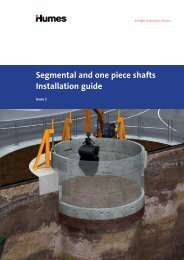
7 Incorporation in vertically cast pipes<br />
7.1 Plastiline sheet shall be so placed on the inner<br />
mould that keys are running in the longitudinal direction.<br />
A short length of each locking key shall be removed to<br />
provide weep channels at intervals of no more than 2.5m<br />
along assembled pipelines, to ensure that there is no<br />
build-up of hydrostatic pressure.<br />
7.2 The sheet shall be placed under slight tension and<br />
held firmly against the inner mould, to prevent leakage of<br />
mortar between blanket and mould. The sheet can be a<br />
pre-formed tube, or blanket held in place initially by metal<br />
or plastic straps and finally secured at the vertical edges<br />
under strips of rigid plastic, held by screws inserted from<br />
inside the mould.<br />
If the lining is a pre-formed tube, relief of hydrostatic<br />
presure is provided by leaving a short length of the<br />
circumference unwelded (at the invert) when the pipeline<br />
is assembled.<br />
7.3 Reinforcement shall be secured by plastic bar<br />
chairs or other method of support which will not damage<br />
the sheet.<br />
7.4 In large diameter vertically cast pipes, adjacent linings<br />
will normally be joined in the assembled pipeline by<br />
102mm joint strip as shown in the joint detail type P1<br />
(see page 11).<br />
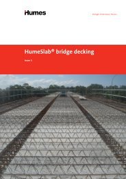
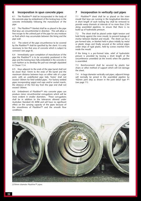
2250mm diameter Plastiline pipes.<br />
10