Wind Turbine Modeling - PowerWorld
Wind Turbine Modeling - PowerWorld
Wind Turbine Modeling - PowerWorld

Create successful ePaper yourself
Turn your PDF publications into a flip-book with our unique Google optimized e-Paper software.
Transient Stability Analysis<br />
with <strong>PowerWorld</strong> Simulator<br />
T12: <strong>Wind</strong> <strong>Turbine</strong> <strong>Modeling</strong><br />
2001 South First Street<br />
Champaign, Illinois 61820<br />
+1 (217) 384.6330<br />
support@powerworld.com<br />
http://www.powerworld.com
Need for <strong>Wind</strong> <strong>Turbine</strong> Models<br />
• Over the last decade<br />
wind turbine capacity<br />
has grown to the point<br />
where they need to be<br />
explicitly considered in<br />
system-wide transient<br />
stability studies<br />
Growth in US <strong>Wind</strong> Capacity<br />
http://www.awea.org/publications/reports/AWEA-Annual-<strong>Wind</strong>-Report-2009.pdf<br />
T12: <strong>Wind</strong> <strong>Turbine</strong><br />
© 2012 <strong>PowerWorld</strong> Corporation<br />
2
<strong>Wind</strong> <strong>Turbine</strong> <strong>Modeling</strong><br />
• A wind farm usually consists of many small turbines in a<br />
collector system<br />
• Each turbine’s voltage is usually less than 1 kV (usually 600<br />
V) with a step-up transformer (usually to 34.5 kV)<br />
• Usually, the wind farm is modeled in aggregate, but how<br />
accurate such aggregate models are is an open question<br />
• <strong>PowerWorld</strong> Simulator provides support of each of the four<br />
major types of wind turbine models used in transient<br />
stability studies<br />
– Type 1: Induction generator with fixed rotor resistance<br />
– Type 2: Induction generators with variable rotor resistance<br />
– Type 3: Doubly-fed induction generators<br />
– Type 4: Full converter generators<br />
• New wind turbines are either Type 3 or Type 4<br />
T12: <strong>Wind</strong> <strong>Turbine</strong><br />
© 2012 <strong>PowerWorld</strong> Corporation<br />
3
<strong>Wind</strong> <strong>Turbine</strong> <strong>Modeling</strong>:<br />
Power Flow Solution<br />
• <strong>Wind</strong> turbines are represented as generators in<br />
the power flow<br />
– Type 1 and 2 units operate at fixed real/reactive<br />
power with the unit supplying real power and<br />
consuming reactive power; usually there are<br />
compensating capacitors<br />
– Type 3 and 4 are treated as regular PV buses<br />
T12: <strong>Wind</strong> <strong>Turbine</strong><br />
© 2012 <strong>PowerWorld</strong> Corporation<br />
4
<strong>Wind</strong> Generator Models<br />
• <strong>Wind</strong> <strong>Turbine</strong>s do not have an “exciter”, “governor”, or<br />
“stabilizer”<br />
• However, modeling is very analogous<br />
– <strong>Wind</strong> Machine Model = Machine Model<br />
– <strong>Wind</strong> Electrical Model = Exciter<br />
– <strong>Wind</strong> Mechanical Model = Governor<br />
– <strong>Wind</strong> Pitch Control = Stabilizer<br />
– <strong>Wind</strong> Aerodynamic Model = Stabilizer<br />
• Simulator will show wind models listed as though they<br />
are Exciters, Governors, and Stabilizers<br />
– Obviously you should not use a synchronous machine<br />
exciter in combination with a wind machine model and wind<br />
governor!<br />
T12: <strong>Wind</strong> <strong>Turbine</strong><br />
© 2012 <strong>PowerWorld</strong> Corporation<br />
5
Generic <strong>Wind</strong> <strong>Turbine</strong> Models<br />
Type 1 Type 2 Type 3 Type 4<br />
GE DYD PSS/E DYR GE DYD PSS/E DYR GE DYD PSS/E DYR GE DYD PSS/E DYR<br />
Machine WT1G WT1G1 WT2G WT2G1 WT3G WT3G1,<br />
WT3G2<br />
• Old Type 1 models as induction machine<br />
– MOTOR1, GENIND<br />
– CIMTR1, CIMTR2, CIMTR3, CIMTR4<br />
• GE-specific Type 2 wind turbine model<br />
– GENWRI, EXWTG1, WNDTRB<br />
• GE-specific Type 3 wind turbine model<br />
– GEWTG, EXWTGE, WNDTGE<br />
– Detailed model for GE 1.5, 1.6 and 3.5 MW turbines<br />
WT4G<br />
WT4G1<br />
“Exciter” WT2E WT2E1 WT3E WT3E1 WT4E WT4E1<br />
“Governor” WT1T WT12T1 WT1T WT12T1 WT3T WT3T1 WT4T<br />
“Stabilizer” WT1P W12A1 WT1P WT12A1 WT3P WT3P1<br />
T12: <strong>Wind</strong> <strong>Turbine</strong><br />
© 2012 <strong>PowerWorld</strong> Corporation<br />
6
<strong>Wind</strong> <strong>Turbine</strong> Voltage Control<br />
• Voltage control of wind turbines depends on the type<br />
• Type 1 squirrel cage induction machines- no direct<br />
voltage control<br />
• Type 2- wound rotor induction machines with variable<br />
external resistance, no direct voltage control, but<br />
external resistance system usually modeled as an exciter<br />
• Type 3 and Type 4- have the ability to perform voltage<br />
or reactive power control, similar to synchronous<br />
machines. Common control modes are constant power<br />
factor control, coordinated control across a wind farm to<br />
maintain a constant interconnection point voltage, and<br />
constant reactive power control<br />
T12: <strong>Wind</strong> <strong>Turbine</strong><br />
Glover, Sarma, Overbye, Power System Analysis and Design<br />
© 2012 <strong>PowerWorld</strong> Corporation<br />
7
<strong>Wind</strong> <strong>Turbine</strong> <strong>Modeling</strong><br />
• Types 1 and 2- Induction machine models, stator windings are<br />
connected to the rest of the network, rotor currents are<br />
induced by the relative motion between the rotating magnetic<br />
field due to the stator currents and the rotor<br />
• Slip is the difference between the synchronous speed and the<br />
rotor speed, defined using motor convention as<br />
S<br />
=<br />
n<br />
s<br />
− n<br />
n<br />
• Synchronous speed is n s an rotor speed is n r , per unit<br />
s<br />
r<br />
+<br />
V t<br />
-<br />
R a<br />
I<br />
jX a<br />
jX m<br />
jX 1<br />
R 1 /S<br />
Equivalent<br />
circuit for a<br />
single cage<br />
induction<br />
machine<br />
T12: <strong>Wind</strong> <strong>Turbine</strong><br />
Glover, Sarma, Overbye, Power System Analysis and Design<br />
© 2012 <strong>PowerWorld</strong> Corporation<br />
8
Type 1 <strong>Wind</strong> Model- WT1G Power<br />
Speed Curve<br />
Real Power<br />
Type 1 generators usually operate with a small negative slip since the<br />
wind turbine causes the machine to spin slightly faster than<br />
synchronous speed<br />
T12: <strong>Wind</strong> <strong>Turbine</strong><br />
2.8<br />
2.6<br />
2.4<br />
2.2<br />
2<br />
1.8<br />
1.6<br />
1.4<br />
1.2<br />
1<br />
0.8<br />
0.6<br />
0.4<br />
0.2<br />
0<br />
-0.2<br />
-0.4<br />
-0.6<br />
-0.8<br />
-1<br />
-1.2<br />
-1.4<br />
-1.6<br />
-1.8<br />
-2<br />
-2.2<br />
-2.4<br />
-2.6<br />
-2.8<br />
Real Power<br />
-0.95-0.9-0.85-0.8-0.75-0.7-0.65-0.6-0.55-0.5-0.45-0.4-0.35-0.3-0.25-0.2-0.15-0.1-0.05 0 0.05 0.1 0.15 0.2 0.25 0.3 0.35 0.4 0.45 0.5 0.55 0.6 0.65 0.7 0.75 0.8 0.85 0.9 0.95<br />
Slip<br />
Real Pow er<br />
© 2012 <strong>PowerWorld</strong> Corporation<br />
1<br />
Values are<br />
calculated<br />
between<br />
a Slip of -1 and 1<br />
9
Type 2 <strong>Wind</strong> Models<br />
Real Power<br />
1.6<br />
1.4<br />
1.2<br />
1<br />
0.8<br />
0.6<br />
0.4<br />
0.2<br />
0<br />
-0.2<br />
-0.4<br />
-0.6<br />
-0.8<br />
-1<br />
-1.2<br />
-1.4<br />
• Type 2 models augment Type 1 by allowing for variable rotor<br />
resistance control in the wound rotor induction generator<br />
• By using turbine speed and electrical power output as inputs to the<br />
control system, the wind turbine can provide a more steady power<br />
output during wind variation<br />
Real Power<br />
external<br />
resistance = 0.05<br />
-1.6<br />
-0.95 -0.9 -0.85 -0.8 -0.75 -0.7 -0.65 -0.6 -0.55 -0.5 -0.45 -0.4 -0.35 -0.3 -0.25 -0.2 -0.15 -0.1 -0.0500.050.10.150.20.250.30.350.40.450.50.550.60.650.70.750.80.850.90.951<br />
Slip<br />
Real Pow er<br />
Real Power<br />
Real Power<br />
0.9<br />
0.8<br />
0.7<br />
0.6<br />
0.5<br />
0.4<br />
external resistance<br />
0.3<br />
0.2<br />
= 0.99 pu<br />
0.1<br />
0<br />
-0.1<br />
-0.2<br />
-0.3<br />
-0.4<br />
-0.5<br />
-0.6<br />
-0.7<br />
-0.8<br />
-0.9<br />
-0.95 -0.9 -0.85 -0.8 -0.75 -0.7 -0.65 -0.6 -0.55 -0.5 -0.45 -0.4 -0.35 -0.3 -0.25 -0.2 -0.15 -0.1 -0.0500.050.10.150.20.250.30.350.40.450.50.550.60.650.70.750.80.850.90.951<br />
Slip<br />
Real Pow er<br />
T12: <strong>Wind</strong> <strong>Turbine</strong><br />
© 2012 <strong>PowerWorld</strong> Corporation<br />
10
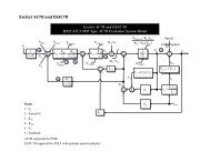
Type 3 <strong>Wind</strong> Models<br />
• Models Doubly-Fed Asynchronous Generators (DFAGs) or<br />
Doubly-Fed Induction Generators (DFIGs)<br />
• In addition to the stator windings, rotor windings are connected<br />
to the AC network through a converter<br />
• Allows separate control of both real and reactive power<br />
• Allows a much wider speed range<br />
• No electrical coupling with the turbine dynamics<br />
• The DFAG dynamics are well approximated as a voltage-source<br />
converter (VSC)<br />
Output from<br />
reactive power<br />
control system<br />
E q<br />
−1<br />
X eq<br />
I q<br />
I p<br />
High/Low<br />
Voltage<br />
Management<br />
I sorc<br />
V∠θ<br />
jX eq<br />
I<br />
Network<br />
Type 3 DFAG Model, Voltage Source Converter (VSC)<br />
Glover, Sarma, Overbye, Power System Analysis and Design<br />
T12: <strong>Wind</strong> <strong>Turbine</strong><br />
© 2012 <strong>PowerWorld</strong> Corporation<br />
11
Type 3 <strong>Wind</strong> Models<br />
• Physically, these models usually consist of a wound rotor<br />
induction machine coupled with a voltage-source converter<br />
AC excitation system<br />
• Electrical performance is dominated by the converter which<br />
acts on a much faster time scale than transient stability level<br />
dynamics<br />
– Machine model consists of a synthesized voltage behind a<br />
reactance<br />
– Rotor dynamics are not important electrically<br />
• <strong>Modeling</strong><br />
– Represents the generator by a machine model<br />
– Reactive power control by an exciter model<br />
– Mechanical control by a governor model<br />
– Blade pitch control by a stabilizer model<br />
T12: <strong>Wind</strong> <strong>Turbine</strong><br />
© 2012 <strong>PowerWorld</strong> Corporation<br />
12
Type 3 <strong>Wind</strong> Model Example<br />
• Generator 3 will be modeled using a GEWTG<br />
machine, which models a 85 MW aggregation<br />
of GE 1.5 MW DFIGs<br />
• Exciter model EXWTGE will be used to model<br />
the reactive power control of the wind turbine<br />
• Governor model WNTDGE will be used to<br />
model the inertia of the wind turbine and its<br />
pitch control<br />
• Generators 1 and 2 remain unchanged<br />
• Open the case which has these settings,<br />
wscc_9bus_Type3WTG.pwb<br />
T12: <strong>Wind</strong> <strong>Turbine</strong><br />
© 2012 <strong>PowerWorld</strong> Corporation<br />
wscc_9bus_Type3WTG<br />
13
Type 3 <strong>Wind</strong> Model Example<br />
• Set up Plot Definitions as desired<br />
• Click “Run transient Stability”<br />
90<br />
85<br />
80<br />
75<br />
70<br />
65<br />
60<br />
1.05<br />
1<br />
0.95<br />
0.9<br />
0.85<br />
0.8<br />
0.75<br />
0.7<br />
0.65<br />
0.6<br />
0.55<br />
0.5<br />
0.45<br />
0.4<br />
0.35<br />
0.3<br />
0.25<br />
0.2<br />
0.15<br />
0.1<br />
0.05<br />
0<br />
0<br />
1<br />
2<br />
3<br />
4<br />
5<br />
6<br />
7<br />
8<br />
Voltage recovery<br />
9<br />
10<br />
V (pu)_Bus Bus1 V (pu)_Bus Bus 2 V (pu)_Bus Bus 3<br />
V (pu)_Bus Bus 4 V (pu)_Bus Bus 5 V (pu)_Bus Bus 6<br />
V (pu)_Bus Bus 7 V (pu)_Bus Bus 8 V (pu)_Bus Bus 9<br />
11<br />
12<br />
13<br />
14<br />
15<br />
16<br />
17<br />
18<br />
19<br />
20<br />
2.5<br />
2.4<br />
2.3<br />
2.2<br />
2.1<br />
2<br />
1.9<br />
1.8<br />
1.7<br />
1.6<br />
1.5<br />
55<br />
50<br />
45<br />
40<br />
35<br />
30<br />
25<br />
20<br />
15<br />
10<br />
5<br />
0<br />
0<br />
1<br />
2<br />
3<br />
4<br />
5<br />
<strong>Wind</strong> turbine MW<br />
Mechanical input and<br />
terminal output<br />
6<br />
7<br />
8<br />
9<br />
10<br />
Mech Input_Gen Bus1 #1 MW Terminal_Gen Bus1 #1 Mech Input_Gen Bus 3 #1<br />
MW Terminal_Gen Bus 3 #1 Mech Input_Gen Bus 2 #1 MW Terminal_Gen Bus 2 #1<br />
Generator 3<br />
EXWTGE states<br />
11<br />
12<br />
13<br />
14<br />
15<br />
16<br />
17<br />
18<br />
19<br />
20<br />
1.4<br />
1.3<br />
1.2<br />
1.1<br />
1<br />
0.9<br />
0<br />
1<br />
2<br />
3<br />
4<br />
5<br />
6<br />
7<br />
8<br />
9<br />
10<br />
11<br />
12<br />
13<br />
14<br />
15<br />
16<br />
17<br />
18<br />
19<br />
20<br />
T12: <strong>Wind</strong> <strong>Turbine</strong><br />
States of Exciter\EField_Gen Bus1 #1 States of Exciter\Sensed Vt_Gen Bus1 #1<br />
States of Exciter\VR_Gen Bus1 #1 States of Exciter\VF_Gen Bus1 #1<br />
© 2012 <strong>PowerWorld</strong> Corporation<br />
wscc_9bus_Type3WTG<br />
14
Type 3 <strong>Wind</strong> Model Example<br />
• During the fault the wind turbine terminal bus voltage will be quite<br />
low. This will cause the turbine’s Low Voltage Power Logic (LVPL) to<br />
reduce the real power current to zero.<br />
• This will cause the wind turbine pitch<br />
control system to begin to pitch the blades<br />
to reduce the mechanical power into the<br />
rotor. This pitch control occurs slowly.<br />
0.158<br />
0.156<br />
0.154<br />
0.152<br />
0.15<br />
0.148<br />
0.146<br />
0.144<br />
0.142<br />
0.14<br />
0.138<br />
0.136<br />
0.134<br />
0.132<br />
0.13<br />
0.128<br />
0.126<br />
0.124<br />
0.122<br />
0.12<br />
0<br />
T12: <strong>Wind</strong> <strong>Turbine</strong><br />
1<br />
2<br />
3<br />
4<br />
5<br />
<br />
6<br />
7<br />
Generator 1<br />
<strong>Turbine</strong> Power<br />
8<br />
9<br />
10<br />
11<br />
12<br />
13<br />
14<br />
15<br />
States of Governor\<strong>Turbine</strong> Pow er, Gen '1' '1'<br />
16<br />
17<br />
18<br />
19<br />
20<br />
© 2012 <strong>PowerWorld</strong> Corporation<br />
3<br />
2.8<br />
2.6<br />
2.4<br />
2.2<br />
2<br />
1.8<br />
1.6<br />
1.4<br />
1.2<br />
1<br />
0.8<br />
0.6<br />
0.4<br />
0.2<br />
0<br />
0<br />
1<br />
2<br />
3<br />
4<br />
5<br />
<br />
<br />
<br />
<br />
6<br />
7<br />
Pitch<br />
8<br />
9<br />
10<br />
11<br />
12<br />
13<br />
States of Governor\Pitch_Gen '3' '1'<br />
14<br />
States of Governor\Pitch Control_Gen '3' '1'<br />
States of Governor\Pitch Compensation_Gen '3' '1'<br />
States of Governor\Mech Speed_Gen '3' '1'<br />
• Once the fault is cleared, this current<br />
is ramped back up, subject to a rate<br />
limit.<br />
wscc_9bus_Type3WTG<br />
15<br />
16<br />
17<br />
18<br />
19<br />
20<br />
15
Example: Impact of a Complex Load<br />
• The way load dynamics are modeled often has a significant impact<br />
on the results of transient stability studies<br />
• So far, we have mostly been looking at generator models, but many<br />
load models are also available in Simulator<br />
• The default (global) models are specified on the Options, Power<br />
System Model page as constant impedance loads<br />
– Used when no other model is specified<br />
– Discussed in the Transient Stability Basics section<br />
• Simulator makes it very easy to add complex load models<br />
• More detailed models are added by selecting “Stability Case Info”<br />
from the ribbon, then Case Information, Load Characteristics Models.<br />
• Models can be specified for the entire case (system), or individual<br />
areas, zones, owners, buses or loads.<br />
• To insert a load model, right-click and select “Insert”<br />
to display the Load Characteristic Information dialog.<br />
T12: <strong>Wind</strong> <strong>Turbine</strong><br />
© 2012 <strong>PowerWorld</strong> Corporation<br />
16
Complex Load Example<br />
• Add a CLOD model to the system<br />
– Go to the Load Characteristic page<br />
in Model Explorer<br />
– Right-click and choose “insert” to<br />
open the Load Characteristic<br />
information dialog<br />
• In the dialog, click “System” in the<br />
Element Type box to apply the<br />
load model to all buses in the<br />
system<br />
• Click “Insert” to select the model<br />
type. Use CLOD (see [1]), which<br />
models the load as a combination of<br />
large and small induction motors,<br />
constant power and discharge<br />
lighting loads<br />
Applies at the system level<br />
Insert a CLOD model<br />
[1] J.A. Diaz de Leon II, B. Kehrli, “The <strong>Modeling</strong> Requirements for Short-Term Voltage Stability Studies,” Power Systems<br />
Conference and Exposition (PSCE), Atlanta, GA, October, 2006, pp. 582-588.<br />
T12: <strong>Wind</strong> <strong>Turbine</strong><br />
© 2012 <strong>PowerWorld</strong> Corporation<br />
17
Complex Load Example<br />
0.151<br />
0.151<br />
0.15<br />
0.15<br />
0.149<br />
0.149<br />
0.148<br />
0.148<br />
0.147<br />
0.147<br />
0.146<br />
0.146<br />
0.145<br />
0.145<br />
0.144<br />
0.144<br />
0.143<br />
0.143<br />
0.142<br />
0.142<br />
0.141<br />
0.141<br />
0.14<br />
0.14<br />
0.139<br />
• The case with these settings is wscc_9bus_Type3WTG_CLOD<br />
• Run the simulation<br />
• Compare the plots obtained with and without the CLOD load<br />
model<br />
0<br />
1<br />
2<br />
3<br />
4<br />
5<br />
<br />
6<br />
7<br />
8<br />
9<br />
10<br />
11<br />
12<br />
13<br />
14<br />
15<br />
States of Governor\<strong>Turbine</strong> Pow er_Gen '1' '1'<br />
Plots after inserting system-level CLOD model<br />
16<br />
17<br />
18<br />
19<br />
20<br />
1.05<br />
1<br />
0.95<br />
0.9<br />
0.85<br />
0.8<br />
0.75<br />
0.7<br />
0.65<br />
0.6<br />
0.55<br />
0.5<br />
0.45<br />
0.4<br />
0.35<br />
0.3<br />
0.25<br />
0.2<br />
0.15<br />
0.1<br />
0.05<br />
0<br />
0<br />
1<br />
2<br />
<br />
<br />
<br />
3<br />
4<br />
5<br />
6<br />
V (pu)_Bus '1' <br />
V (pu)_Bus '5' <br />
V (pu)_Bus '9'<br />
7<br />
8<br />
9<br />
10<br />
V (pu)_Bus '2' <br />
V (pu)_Bus '6' <br />
11<br />
12<br />
13<br />
14<br />
V (pu)_Bus '3' <br />
V (pu)_Bus '7' <br />
15<br />
16<br />
17<br />
V (pu)_Bus '4'<br />
V (pu)_Bus '8'<br />
18<br />
19<br />
20<br />
T12: <strong>Wind</strong> <strong>Turbine</strong><br />
© 2012 <strong>PowerWorld</strong> Corporation<br />
wscc_9bus_Type3WTG_CLOD<br />
18
Complex Load Example<br />
• On the Simulation page, increase the time<br />
for when the line is opened from 1.12<br />
seconds to 1.155 seconds<br />
• Open the Events tab on the Results page<br />
• The Transient Contingency events are<br />
there, but there are also under voltage<br />
load trip events present<br />
1.1<br />
1<br />
0.9<br />
0.8<br />
0.7<br />
0.6<br />
0.5<br />
0.4<br />
0.3<br />
0.2<br />
0.1<br />
0<br />
0<br />
1<br />
2 3 4 5 6 7 8 9 10 11 12 13 14 15 16 17 18<br />
V (pu)_Bus Bus1 V (pu)_Bus Bus 2 V (pu)_Bus Bus 3<br />
V (pu)_Bus Bus 4 V (pu)_Bus Bus 5 V (pu)_Bus Bus 6<br />
V (pu)_Bus Bus 7 V (pu)_Bus Bus 8 V (pu)_Bus Bus 9<br />
19<br />
20<br />
T12: <strong>Wind</strong> <strong>Turbine</strong><br />
© 2012 <strong>PowerWorld</strong> Corporation<br />
wscc_9bus_Type3WTG_CLOD<br />
19
Complex Load Example<br />
• In the <strong>PowerWorld</strong> CLOD model, under-voltage motor tripping may be<br />
set by the following parameters<br />
– Vi = voltage at which trip will occur (default = 0.75 pu)<br />
– Ti (cycles) = length of time voltage needs to be below Vi before trip will occur<br />
• In the example, under voltage trips occurred at bus 5 and bus 8 when<br />
the fault clearing time was increased to 1.155<br />
• Verify that increasing the clearing time further to 1.2 causes additional<br />
under-voltage trips of loads at buses 6, and an over-frequency trip of<br />
Generator 2<br />
Mechanical Power (MW)<br />
160<br />
150<br />
140<br />
130<br />
120<br />
110<br />
100<br />
90<br />
80<br />
70<br />
60<br />
50<br />
40<br />
30<br />
20<br />
0<br />
1<br />
2<br />
3<br />
cleared at 1.155 seconds<br />
4 5 6 7 8 9 10 11 12 13 14 15 16 17 18 19 20<br />
Time (Seconds)<br />
Generator<br />
Pmech<br />
Mechanical Power (MW)<br />
160<br />
140<br />
120<br />
100<br />
80<br />
60<br />
40<br />
20<br />
0<br />
0<br />
1<br />
2<br />
3<br />
4<br />
cleared at 1.2 seconds<br />
5 6 7 8 9 10 11 12 13 14 15 16 17 18 19<br />
Time (Seconds)<br />
20<br />
Mech Input_Gen Bus 2 #1 Mech Input_Gen Bus 3 #1 Mech Input_Gen Bus1 #1<br />
Mech Input_Gen Bus 2 #1 Mech Input_Gen Bus 3 #1 Mech Input_Gen Bus1 #1<br />
T12: <strong>Wind</strong> <strong>Turbine</strong><br />
© 2012 <strong>PowerWorld</strong> Corporation<br />
wscc_9bus_Type3WTG_CLOD<br />
20
Complex Load Example<br />
3<br />
2.8<br />
2.6<br />
2.4<br />
2.2<br />
2<br />
1.8<br />
1.6<br />
1.4<br />
1.2<br />
1<br />
0.8<br />
0.6<br />
0.4<br />
0.2<br />
0<br />
-0.2<br />
Plots when fault is cleared at 1.2<br />
seconds<br />
0<br />
1<br />
2<br />
3<br />
4<br />
5<br />
6<br />
7<br />
8<br />
Generator<br />
exciter states<br />
9<br />
States of Exciter\EField_Gen Bus1 #1 States of Exciter\Sensed Vt_Gen Bus1 #1<br />
States of Exciter\VR_Gen Bus1 #1 States of Exciter\VF_Gen Bus1 #1<br />
10<br />
11<br />
12<br />
13<br />
14<br />
15<br />
16<br />
17<br />
18<br />
19<br />
20<br />
Large and Small Induction Motor Loads<br />
experience under voltage trips at buses 5,6,<br />
and 8 at about 2 seconds after the line opens<br />
Generator 2 opens due to over<br />
frequency at 4.2 seconds after the line<br />
recloses<br />
1.2<br />
1.1<br />
1<br />
0.9<br />
0.8<br />
0.7<br />
0.6<br />
0.5<br />
0.4<br />
0.3<br />
0.2<br />
0.1<br />
0<br />
0<br />
1<br />
2<br />
3<br />
4<br />
5<br />
6<br />
Voltages<br />
7<br />
8<br />
9<br />
10<br />
11<br />
12<br />
13<br />
14<br />
15<br />
16<br />
17<br />
18<br />
19<br />
20<br />
V (pu)_Bus Bus1 V (pu)_Bus Bus 2 V (pu)_Bus Bus 3<br />
V (pu)_Bus Bus 4 V (pu)_Bus Bus 5 V (pu)_Bus Bus 6<br />
V (pu)_Bus Bus 7 V (pu)_Bus Bus 8 V (pu)_Bus Bus 9<br />
T12: <strong>Wind</strong> <strong>Turbine</strong><br />
© 2012 <strong>PowerWorld</strong> Corporation<br />
wscc_9bus_Type3WTG_CLOD<br />
21
Complex Load Example<br />
1.1<br />
1<br />
0.9<br />
0.8<br />
0.7<br />
0.6<br />
0.5<br />
0.4<br />
0.3<br />
0.2<br />
0.1<br />
0<br />
0<br />
• CLOD model under-voltage tripping can be turned off by setting its<br />
parameter Vi to zero<br />
• Re-open the CLOD dialog, and set Vi to zero<br />
• Run the simulation, clearing<br />
the fault at 1.2 seconds<br />
• Compare the plots<br />
1<br />
2<br />
3<br />
V (pu)_Bus Bus1 V (pu)_Bus Bus 2 V (pu)_Bus Bus 3<br />
V (pu)_Bus Bus 4 V (pu)_Bus Bus 5 V (pu)_Bus Bus 6<br />
V (pu)_Bus Bus 7 V (pu)_Bus Bus 8 V (pu)_Bus Bus 9<br />
Voltages with undervoltage<br />
tripping turned<br />
OFF<br />
T12: <strong>Wind</strong> <strong>Turbine</strong><br />
4<br />
5<br />
6<br />
7<br />
8<br />
9<br />
10<br />
11<br />
12<br />
13<br />
14<br />
15<br />
16<br />
17<br />
18<br />
19<br />
20<br />
1.2<br />
1.1<br />
1<br />
0.9<br />
0.8<br />
0.7<br />
0.6<br />
0.5<br />
0.4<br />
0.3<br />
0.2<br />
0.1<br />
0<br />
0<br />
160<br />
150<br />
140<br />
130<br />
120<br />
110<br />
100<br />
90<br />
1 2 3 4 5 6 7 8 9 10 11 12 13 14 15 16 17 18 19 20 80<br />
70<br />
V (pu)_Bus Bus1 V (pu)_Bus Bus 2 V (pu)_Bus Bus 3<br />
60<br />
50<br />
V (pu)_Bus Bus 4 V (pu)_Bus Bus 5 V (pu)_Bus Bus 6<br />
40<br />
V (pu)_Bus Bus 7 V (pu)_Bus Bus 8 V (pu)_Bus Bus 9<br />
30<br />
20<br />
10<br />
0<br />
-10<br />
0 1<br />
Voltages with undervoltage<br />
tripping turned<br />
ON (default)<br />
© 2012 <strong>PowerWorld</strong> Corporation<br />
Mechanical Power (MW)<br />
Set to zero to turn off<br />
under-voltage tripping<br />
Time (Seconds)<br />
Mech Input_Gen Bus 2 #1 Mech Input_Gen Bus 3 #1<br />
Mech Input_Gen Bus1 #1<br />
wscc_9bus_Type3WTG_CLOD<br />
2<br />
3<br />
4<br />
5<br />
6<br />
7<br />
8<br />
9 10 11 12 13 14 15 16 17 18 19 20<br />
22
Type 4 <strong>Wind</strong> Models<br />
• Completely asynchronous by design, called a “full converter<br />
model”<br />
• The wind turbine’s output is completely decoupled from the<br />
network using an AC-DC-AC converter<br />
• This decoupling allows considerable freedom in selecting<br />
what type of electric machine is used<br />
– Machine could be a conventional synchronous generator,<br />
permanent magnet synchronous generator, or squirrel cage<br />
induction machine<br />
– No electrical coupling with the turbine dynamics<br />
• Represented as a VSC, like Type 3, but with I p and I q as direct<br />
control variables and without effective reactance<br />
• Modeled<br />
– Machine/Exciter combination WT4G1/WT4E1 (PSSE)<br />
T12: <strong>Wind</strong> <strong>Turbine</strong><br />
– Machine/Exciter/Governor WT4G, WT4E, and WT4T (PSLF)<br />
© 2012 <strong>PowerWorld</strong> Corporation<br />
23