OPERATION MANUAL for DEWALD HYDRAULIC ... - Power Gear
OPERATION MANUAL for DEWALD HYDRAULIC ... - Power Gear
OPERATION MANUAL for DEWALD HYDRAULIC ... - Power Gear

Create successful ePaper yourself
Turn your PDF publications into a flip-book with our unique Google optimized e-Paper software.
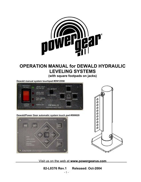
<strong>OPERATION</strong> <strong>MANUAL</strong> <strong>for</strong> <strong>DEWALD</strong> <strong>HYDRAULIC</strong><br />
LEVELING SYSTEMS<br />
(with square footpads on jacks)<br />
Dewald manual system touchpad #DN12558<br />
Dewald/<strong>Power</strong> <strong>Gear</strong> automatic system touch pad #500629<br />
Visit us on the web at www.powergearus.com<br />
82-L0376 Rev.1 Released: Oct-2004<br />
- 1 -
TABLE OF CONTENTS<br />
Page 3:<br />
Page 6:<br />
Page 9:<br />
Page 10:<br />
Page 11:<br />
Page 12:<br />
Leveling procedures <strong>for</strong> Dewald Manual Leveling System<br />
Leveling procedure <strong>for</strong> Dewald/<strong>Power</strong> <strong>Gear</strong> Automatic leveling System<br />
Manual retraction procedure<br />
Preventive maintenance<br />
Troubleshooting guide<br />
Warranty in<strong>for</strong>mation<br />
- 2 -
LEVELING PROCEDURES FOR <strong>DEWALD</strong> <strong>MANUAL</strong><br />
LEVELING SYSTEM<br />
Dewald manual system touchpad #DN12558<br />
Park brake must be set be<strong>for</strong>e jacks will operate.<br />
NOTES BEFORE YOU LEVEL YOUR COACH<br />
When looking <strong>for</strong> a leveling site, always make sure the surface is as level as possible.<br />
Check leveling site to make sure obstructions have been cleared away <strong>for</strong> proper jack operation.<br />
Keep people clear of coach prior to turning the leveling system on and while leveling system is in use.<br />
Never expose hands or other parts of the body near hydraulic leaks. High-pressure oil leaks may cut<br />
and penetrate the skin causing serious injury.<br />
WARNING<br />
This is a leveling system only and is not intended to lift your coach<br />
completely off the ground. Attempting to lift your coach completely off<br />
the ground (<strong>for</strong> example, to use this leveling system to change a tire)<br />
could cause damage to the system and serious injury to the parties<br />
involved. If a tire should require changing please have the proper<br />
equipment and contact a professional.<br />
Important: if your coach is equipped with a slide out(s) always level your unit first, and then<br />
operate the slide out room(s). When retracting the slide(s), always retract the room(s) first then retract<br />
the leveling jacks. Following this procedure will produce the least amount of stress on your chassis.<br />
- 3 -
STEP 1:<br />
Turn the Leveling <strong>Power</strong> Panel On. (System <strong>Power</strong> Switch “A”)<br />
This should be turned on only when leveling operation is required and turned off when<br />
finished.<br />
Note: If your coach is equipped with air suspension, you may have an air dump switch on or near the<br />
control panel. Exhaust the air from the suspension per vehicle manufacture instructions and then<br />
proceed with leveling of coach. THIS MUST BE DONE BEFORE PROCEEDING TO STEP 2.<br />
STEP 2:<br />
Extend the Leveling Jacks (All Extend Switch “B”)<br />
Hold this switch “on” until you feel all the jacks contact the ground.<br />
STEP 3:<br />
Level The Coach (Leveling Switches “C-F”)<br />
Switches C through F are <strong>for</strong> leveling the coach only.<br />
1. Press switch “C” and lift the front of the coach at least 3 inches. This is important and necessary<br />
to allow the coach to pivot when leveling side to side. If there is insufficient jack stroke to lift the<br />
front of the coach at least 3 inches the coach will have to be moved to an area with less front to<br />
back slope.<br />
2. Extend front or rear jacks as necessary to level the coach from front to rear.<br />
3. Press switch “D” or “F” to level the coach from side to side.<br />
The front two jacks work together with switch “C” to raise the front of the coach. The back two jacks<br />
work together with switch “E” to raise the rear of the coach. The right rear works to raise the right<br />
side of the coach with switch “D”. The left rear works to raise the left side of the coach with switch<br />
“F”.<br />
Front Switch (C)<br />
Levels using the front jacks.<br />
Left Switch (F)<br />
Levels using the left rear jack.<br />
Right Switch (D)<br />
Levels using the right rear jack.<br />
Rear Switch (E)<br />
Levels using the rear jacks.<br />
STEP 4:<br />
Retract the Leveling Jacks (All Retract Switch “G”)<br />
Automatic Retract: just trip the switch momentarily and all jacks will automatically retract.<br />
This is the proper way to retract your jacks. This is the only retract switch that will give you a<br />
green light on the power board.<br />
Note: To stop jacks <strong>for</strong> any reason while system is in this automatic retract mode, press the<br />
System <strong>Power</strong> switch to “Off” and the jacks will stay in that position. Turn the System <strong>Power</strong><br />
back “On” if you want to extend them again.<br />
Emergency Retract Switch (H): This switch is engaged to retract jacks and is not automatic.<br />
Operator must maintain engagement on switch to retract the jacks. If jacks are retracted in<br />
this manner you will NOT receive a green “Jacks Fully Retracted” light on the panel.<br />
CAUTION<br />
Never lift the wheels off the ground when leveling the motor home.<br />
- 4 -
CONTROL PANEL LIGHTS<br />
Jacks Fully Retracted:<br />
Jacks Not Retracted:<br />
This is a green light that signals the jacks are in a retracted position.<br />
Always use the “All Retract” switch when retracting jacks, and the green light<br />
will come on automatically.<br />
This is a red light. It will light when any jack has been extended.<br />
Parking Brake Not Set: This is a red light reminding you that the park brake must be set to level your<br />
coach.<br />
<strong>Power</strong> On:<br />
Is a red light that tells you system power to operate the leveling jacks is on.<br />
ASAC: THE DRIVE AWAY PROTECTION FEATURE<br />
ASAC operates when the park brake is released and the ignition is on, if needed. If the jacks are<br />
extended at this time, ASAC will automatically retract them. There<strong>for</strong>e, ASAC guarantees that you<br />
cannot drive away with jacks in an unsafe condition.<br />
Operation: If the park brake is released while the ignition is on, or the ignition is turned on when the<br />
park brake has already been released, ASAC will operate if the jacks are extended. ASAC will operate<br />
this way even if the control panel “System <strong>Power</strong>” switch is off.<br />
During ASAC operation: you will hear the hydraulic pump run and then shut off when ASAC has<br />
finished. An audible warning will sound, and the “Park Brake Not Set” light will be on as well. This<br />
audible warning shows the operator that ASAC is retracting the jacks, and warns the driver not to<br />
drive away until the operation is complete. When ASAC finishes its cycle, the audible warning sound<br />
will stop. If the control panel power switch is on at this time, you will also see a green light when<br />
ASAC has finished. If the control panel power switch is off, you will see the green light <strong>for</strong> a few<br />
seconds, and then all lights will shut off. It is now safe to drive away.<br />
Note: If the main battery disconnect (“Chassis Disconnect”) has been turned off since the last time<br />
“All Retract” or ASAC has operated, ASAC may still operate once even if the jacks are already<br />
retracted. It will run <strong>for</strong> about 7 seconds while it re-checks to make sure all jacks are fully retracted<br />
and pressurized.<br />
- 5 -
LEVELING PROCEDURES FOR <strong>DEWALD</strong>/POWER GEAR<br />
AUTOMATIC LEVELING SYSTEM<br />
Dewald/<strong>Power</strong> <strong>Gear</strong> automatic system touchpad #500629<br />
Park brake must be set be<strong>for</strong>e jacks will operate.<br />
NOTES BEFORE YOU LEVEL YOUR COACH<br />
Transmission must be in Park or Neutral be<strong>for</strong>e jacks will operate.<br />
When looking <strong>for</strong> a leveling site, always make sure the surface is as level as possible.<br />
Check leveling site to make sure obstructions have been cleared away <strong>for</strong> proper jack operation.<br />
Keep people clear of coach prior to turning the leveling system on and while leveling system is in use.<br />
Never expose hands or other parts of the body near hydraulic leaks. High-pressure oil leaks may cut<br />
and penetrate the skin causing serious injury.<br />
WARNING<br />
This is a leveling system only and is not intended to lift your coach<br />
completely off the ground. Attempting to lift your coach completely off<br />
the ground (<strong>for</strong> example, to use this leveling system to change a tire)<br />
could cause damage to the system and serious injury to the parties<br />
involved. If a tire should require changing please have the proper<br />
equipment and contact a professional.<br />
Important: if your coach is equipped with a slide out(s) always level your unit first, and then<br />
operate the slide out room(s). When retracting the slide(s), always retract the room(s) first then retract<br />
the leveling jacks. Following this procedure will produce the least amount of stress on your chassis.<br />
- 6 -
EXCESS SLOPE<br />
When the coach is parked on an excessive slope the leveling requirements may exceed<br />
the jack lift stroke capability. When this occurs, the 4 orange jack lights and the center all<br />
level green light will blink. The coach must be moved to a more level surface, or can be<br />
leveled manually.<br />
STEP 1 - Push "ON/OFF" pad on control panel.<br />
The system is now operational and the electronic level lights will become active.<br />
STEP 2 – Check to see that the touch-pad parking brake light is not flashing.<br />
Engage parking brake if parking brake light is flashing.<br />
STEP 3 – Push the “Auto” pad to begin the automatic leveling cycle.<br />
CAUTION: After starting the automatic leveling cycle it is very important that you do not move<br />
around in the coach until the unit is level and the green <strong>Power</strong> <strong>Gear</strong> Level light illuminates in the<br />
center of the touch pad. Failure to remain still during the leveling cycle could have an affect on<br />
the per<strong>for</strong>mance of the leveling system.<br />
STEP 4 – Leveling with “manual” mode.<br />
If you feel that further adjustments are necessary, simply push and hold the “MAN” pad <strong>for</strong><br />
approximately 5 seconds until the light under this button is illuminated. Push the appropriate leg pad to<br />
override the system and level the coach to your liking.<br />
Note: When leveling the coach in manual mode, the jack(s) will “hesitate” <strong>for</strong> approximately 5<br />
seconds as the controls “sense” that the coach is passing through the programmed zero point (all<br />
level).<br />
Note: When in the manual mode, if the retract button is pushed the jacks will only retract as long as<br />
the button is depressed.<br />
STEP 5 – Push “ON/OFF” pad to de-energize the system.<br />
CAUTION<br />
Never lift the wheels off the ground when leveling the motor home.<br />
DRIVE AWAY PROTECTION SYSTEM<br />
If the ignition is in the “RUN” position, jacks are down, and the operator takes the transmission out of<br />
neutral or park, or releases the parking brake, the “JACKS DOWN” indicator will flash and the alarm<br />
beeper will activate. The system will then automatically retract the jacks until the jacks are fully<br />
retracted<br />
- 7 -
NOTE: Coach ignition must be on.<br />
JACK RETRACT PROCEDURES<br />
STEP 1 - Energize the system by pushing "ON/OFF" pad on control panel.<br />
The "ON/OFF" and “JACKS DOWN” lights will be lit.<br />
STEP 2 - Push and release the "RETRACT ALL JACKS" pad.<br />
All the jacks will start to retract and return to the full retract position automatically. When all jacks return<br />
to full retract position the "JACKS DOWN" light will go out.<br />
STEP 3 - When the "JACKS DOWN" light goes out push the "ON/OFF" pad on the control<br />
panel to de-energize the system.<br />
After a visual inspection around the coach to verify the jacks are fully retracted, you may proceed to<br />
travel.<br />
AUTOMATIC SAFETY SHUTOFF FEATURE<br />
If the touch panel is left on and inactive <strong>for</strong> four minutes it will shut off automatically.<br />
To reset the system the coach ignition must be turned off, then back on.<br />
- 8 -
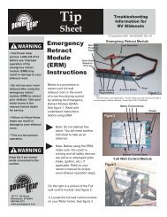
<strong>MANUAL</strong> RETRACTION PROCEDURE<br />
Note: Please read the entire manual be<strong>for</strong>e operating this system.<br />
Your Dewald Hydraulic <strong>Power</strong> System has been designed to operate both the leveling and<br />
slide out system from one power source. This power unit has a built-in hand pump <strong>for</strong><br />
manually retracting the jacks and slide out room(s) if complete power should be lost to your<br />
leveling system.<br />
Hand Pump Operation<br />
1. Turn each of the small slotted setscrews (A) on the front of the pump assembly clockwise until they<br />
stop. This will hold the valves open.<br />
Note: Coaches that pre-date 2001 may have a red knurled knob on the end of each valve<br />
(A). Instead of turning a setscrew as instructed, you simply pull out the red knobs and turn<br />
them a ¼ turn in either direction. When you release them, they will stay locked in the "out"<br />
position.<br />
2. Turn the silver (larger) knurled knob (B) on the front of the power unit 2 turns counter-clockwise.<br />
3. Insert the pump handle into the receptacle (C) and pump the hand pump.<br />
4. When all the jacks and the slide out room(s) are fully retracted, tightly close the silver knurled knob<br />
clockwise.<br />
5. Turn each of the small slotted setscrews counter-clockwise, until snug.<br />
Note: If equipped with red knobs (A), turn them a ¼ turn to pop them back into normal<br />
operating position.<br />
Note: Number of valves (A) shown will vary depending on how many slide rooms are operated by the<br />
pump assembly.<br />
Please read the owners’ manual from the manufacturer who built and designed your<br />
motor home <strong>for</strong> further leveling and slide out room operating in<strong>for</strong>mation and safety<br />
features.<br />
- 9 -
PREVENTIVE MAINTENANCE<br />
1. Check the fluid level every month.<br />
2. Check and/or fill the reservoir with the jacks and room(s) in the fully retracted position.<br />
3. The fluid should be within 1/2 inch of the top of the reservoir tank.<br />
4. Change fluid every 24 months.<br />
5. Inspect and clean all hydraulic pump electrical connections every 12 months.<br />
6. Remove dirt and road debris from jacks as needed.<br />
7. If jacks are down <strong>for</strong> extended periods, it is recommended to spray exposed leveling jack rods with a<br />
silicone lubricant every 5 to 7 days <strong>for</strong> protection.<br />
8. If your coach is located in a salty environment (within 60 miles of coastal areas),<br />
it is recommended to spray the rods every 2 to 3 days with a silicone lubricant.<br />
RECOMMENDED <strong>HYDRAULIC</strong> FLUIDS FOR YOUR <strong>DEWALD</strong> <strong>HYDRAULIC</strong> PUMP<br />
The fluids listed here are acceptable to use in your pump assembly. Contact coach manufacturer or<br />
selling dealer <strong>for</strong> in<strong>for</strong>mation about what specific fluid was installed in your system.<br />
It is not recommended that hydraulic fluid and automatic transmission fluids be mixed in the<br />
reservoir.<br />
In most applications, Type A automatic transmission fluid (ATF, Dexron III, etc.,) will work satisfactorily. Mercon<br />
V is also recommended as an alternative fluid <strong>for</strong> Dewald hydraulic systems.<br />
If operating in cold temperatures (less than -10 F) the jacks may extend and retract slowly.<br />
For cold weather operation, fluid specially-<strong>for</strong>mulated <strong>for</strong> low temperatures may be desirable. Mobil DTE 11M,<br />
Texaco Rando HDZ-15HVI, Kendall Hyden Glacial Blu, or any Mil. Spec. H5606 hydraulic fluids are<br />
recommended <strong>for</strong> cold weather operation.<br />
Please consult factory be<strong>for</strong>e using any other fluids than those specified here.<br />
WARNING<br />
Your coach should be supported at both front and rear axles with jack<br />
stands be<strong>for</strong>e working underneath, failure to do so may result in personal<br />
injury or death.<br />
- 10 -
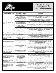
TROUBLESHOOTING<br />
System will not turn on and "on/off" indicator light will not illuminate<br />
Touchpad # Probable Cause Corrective Action<br />
Both Batteries disconnected Reconnect batteries, and/or check connections<br />
Battery voltage low (below 9.5 volts)<br />
Recharge batteries or replace if necessary<br />
DN12558 Check connection of 6-pin harness on back of touch pad Unplug and reconnect as necessary<br />
Check <strong>for</strong> a blown fuse on the 6-pin harness that plugs into the<br />
back of the touch pad<br />
Replace fuse with 6.25 amp Slo-Blo fuse<br />
500629 Ignition must be in run position Turn ignition to run position<br />
Park brake must be set<br />
Set parking brake<br />
Transmission not in park or neutral<br />
Take coach out of gear<br />
Leveling control has timed out and shut down<br />
Turn off touch pad <strong>for</strong> a moment, then turn back on<br />
System is on, but pump won't run<br />
Touchpad # Probable Cause Corrective Action<br />
Both<br />
DN12558<br />
Bad connection of motor ground wire at pump<br />
Park brake must be set<br />
Check grounding of black wire coming directly out of 12v motor at<br />
the pump assembly<br />
Set parking brake<br />
500629<br />
All four orange level lights and center green "all level” light are<br />
blinking<br />
Coach is parked on an excessive slope. Move coach to a more<br />
level sight. If coach is already parked on a known level sight, then<br />
electric controls need calibrated (see TIP sheet # 153)<br />
Pump runs, but jacks do not extend<br />
Touchpad # Probable Cause Corrective Action<br />
Both<br />
Manual override valves (see label "A", pg 9) are open<br />
Hand pump valve (see label "B", pg 9) is open<br />
Turn slotted setscrews in the end of the valves counter clockwise<br />
until snug. If red knobs, turn until they pop back into position<br />
Turn knob clockwise until snug<br />
Low fluid With all jacks and slide room(s) fully retracted, fluid should be 1/2<br />
inch from the top of the tank reservoir<br />
Pump ran during extension or retraction, then stopped<br />
Touchpad # Probable Cause Corrective Action<br />
Both<br />
Motor overheated, thermal overload protection in motor tripped<br />
Let system rest <strong>for</strong> 5-10 minutes to allow automatic breaker in<br />
motor to reset<br />
Locations of breakers, fuses, fuse panels, etc. are coach specific. Consult your coach owner’s manual<br />
or the coach manufacture <strong>for</strong> locations of these components.<br />
The following in<strong>for</strong>mation will guide you to repairs that may be made on site. For problems not<br />
covered here, contact your service center or our website <strong>for</strong> more extensive troubleshooting<br />
in<strong>for</strong>mation in the service manual <strong>for</strong> your system.<br />
- 11 -
LIMITED WARRANTY<br />
<strong>Power</strong> <strong>Gear</strong> warrants to the original retail purchaser that the product will be free from defects in material and<br />
workmanship <strong>for</strong> a period of two (2) years following the retail sales date. <strong>Power</strong> <strong>Gear</strong> will, at its option, repair<br />
or replace any part covered by this limited warranty, which following examination by <strong>Power</strong> <strong>Gear</strong> or its<br />
authorized distributors or dealers, is found to be defective under normal use and service. No claims under<br />
this warranty will be valid unless <strong>Power</strong> <strong>Gear</strong> or its authorized distributor or dealer is notified in writing of such<br />
claim prior to the expiration of the warranty period. Warranty is transferable pending documentation of<br />
original sale date of product.<br />
THIS WARRANTY SHALL NOT APPLY TO:<br />
• Failure due to normal wear and tear, accident, misuse, abuse, or negligence.<br />
• Products that are modified or altered in a manner not authorized by <strong>Power</strong> <strong>Gear</strong> in writing.<br />
• Failure due to misapplication of product.<br />
• Telephone or other communication expenses.<br />
• Living or travel expenses.<br />
• Overtime labor.<br />
• Failures created by improper installation of the product’s slideout system or slideout room to include final<br />
adjustments made at the plant <strong>for</strong> proper room extension/retraction; sealing interface between slideout<br />
rooms and side walls; synchronization of inner rails; or improper wiring or ground problems.<br />
• Failures created by improper installation of leveling systems, including final adjustments made at the plant,<br />
or low fluid level, wiring or ground problems.<br />
• Replacement of normal maintenance items.<br />
There is no other express warranty other than the <strong>for</strong>egoing warranty. THERE ARE NO IMPLIED<br />
WARRANTIES OF MERCHANTIBILITY OR FITNESS FOR A PARTICULAR PURPOSE. IN NO EVENT<br />
SHALL POWER GEAR BE LIABLE FOR ANY INCIDENTAL OR CONSEQUENTIAL DAMAGES. This<br />
warranty gives you specific legal rights, and you may also have other rights, which vary from state to state.<br />
Some states do not allow the limitations of implied warranties, or the exclusion of incidental or consequential<br />
damages, so the above limitations and exclusions may not apply to you.<br />
For service contact your nearest <strong>Power</strong> <strong>Gear</strong> authorized warranty service facility. Warranty service can be<br />
per<strong>for</strong>med only by a <strong>Power</strong> <strong>Gear</strong> authorized service facility. This warranty will not apply to service at any other<br />
facility. At the time of requesting warranty service, evidence of original purchase date must be presented.<br />
<strong>Power</strong> <strong>Gear</strong><br />
1217 E. 7 th Street<br />
Mishawaka, IN 46544<br />
www.powergearus.com<br />
- 12 -