MCset 4 Civil engineering - Schneider Electric
MCset 4 Civil engineering - Schneider Electric
MCset 4 Civil engineering - Schneider Electric

You also want an ePaper? Increase the reach of your titles
YUMPU automatically turns print PDFs into web optimized ePapers that Google loves.
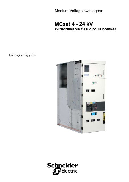
Medium Voltage switchgear<br />
<strong>MCset</strong> 4 - 24 kV<br />
Withdrawable SF6 circuit breaker<br />
<strong>Civil</strong> <strong>engineering</strong> guide
Contents<br />
General 2<br />
Glossary 2<br />
Recommendations 2<br />
Approximate dimensions and weights 3<br />
Gas exhaust version 3<br />
Gas exhaust version with IPX1 protection unit 4<br />
Internal arc version with protection on 3 sides 5<br />
Internal arc version with protection on 4 sides 6<br />
Cubicle AD4 (for unit entry from the top) 8<br />
Cubicles CL4-GL4 (with upstream CT) 8<br />
Switchboard with gas exhaust tunnel 9<br />
Recommendations 9<br />
Installation next to a wall 9<br />
Free-standing installation 9<br />
Building civil <strong>engineering</strong> 10<br />
Gas exhaust version or internal arc version with protection<br />
on 3 sides<br />
0<br />
Internal arc version with protection on 4 sides<br />
1<br />
Cable entry from above version (RHC or RHB)<br />
2<br />
Space to be left around the switchboard<br />
3<br />
Floor preparation 14<br />
Cable entry from below<br />
4<br />
Floor finishing and functional unit fixing 15<br />
Floor finishing<br />
5<br />
Overview of various functional unit fixing methods<br />
5<br />
Cable entry configuration 16<br />
MV cable position for AD4/RD4 cubicle<br />
6<br />
MV cable position for DI4 cubicle<br />
6<br />
Configuration of cable entry from below 17<br />
<strong>Civil</strong> <strong>engineering</strong> with a cable basement<br />
7<br />
<strong>Civil</strong> <strong>engineering</strong> with a cable trench<br />
8<br />
<strong>Schneider</strong> <strong>Electric</strong><br />
07897546EN indice: D0 -
General<br />
Glossary<br />
Nota: this document is available for all the<br />
units ordered from the 1st of March 2008.<br />
FU<br />
Gas exhaust<br />
AD4<br />
RD4<br />
CL4-GL4<br />
TT4<br />
AD4 RHB - RHC<br />
DI4<br />
VT<br />
CT<br />
VPIS<br />
LV<br />
MV<br />
SMALT<br />
JDB<br />
Functional unit (cubicle + mobile part + relay<br />
unit)<br />
Basic version, without internal arc withstand<br />
Incomer / Feeder cubicle<br />
Incomming / outgoing cubicle (without circuit-breaker)<br />
Bus connecting cubicle in a disconnecting line<br />
Measurement and earthing cubicle for busbars<br />
Cubicle with busbar connection from the top<br />
Fuse switch feeder cubicle<br />
Voltage transformer<br />
Current transformer or current sensor<br />
Voltage Presence Indicating System<br />
Low voltage<br />
Voltage class 24kV<br />
Earthing switch<br />
Busbars<br />
Mobile part<br />
SF<br />
OED<br />
Extraction rig<br />
Withdrawable circuit breaker with SF6 breaking used in<br />
AD4 and CL4 cubicles<br />
Tool for extracting, inserting and lower mobile parts on<br />
the floor<br />
Extraction or insertion rig without the capability of<br />
lowering the mobile parts on the floor<br />
Recommendations<br />
Aging resistance of switchgear in an MV substation depends on 3 key factors<br />
- The need for correctly implemented connections<br />
New cold shrinking or threading technologies offer easy installation and help to<br />
improve aging. Their design allows operation in polluted environments with severe<br />
atmospheres.<br />
- Impact of the relative humidity factor<br />
Installing a heating device is essential in climates with high relative humidity levels<br />
and major temperature differences.<br />
Ensure that draughts and / or thermal shocks are avoided in all cubicle compartments<br />
in order to avoid the formation of dew points (sources of partial discharges).<br />
The equipment must be installed in conformity with the relevant IEC standard.<br />
Outside of these normal usage conditions, we recommend contacting<br />
<strong>Schneider</strong> <strong>Electric</strong> to determine the operations to be carried out as well as their<br />
frequency according to the actual service conditions.<br />
- Ventilation control<br />
Dimensions of the ventilation meshes must be suited to the power dissipated in the<br />
substation. These meshes must only be placed near to the transformer to avoid air<br />
circulating around the MV switchboard.<br />
- 07897546EN indice: D0<br />
<strong>Schneider</strong> <strong>Electric</strong>
Approximate dimensions<br />
and weights<br />
Gas exhaust version<br />
Dimensions<br />
AD4 CL4 + GL4 TT4 RD4 DI4<br />
width (mm) 900 900 + 900 900<br />
height (mm) internal arc withstand 25kA - 1s 2325<br />
internal arc withstand 31.5kA - 0.15s 2377 2377<br />
depth (mm) 1750 + 40<br />
Approximate weights (without LV cables or accessories)<br />
AD4* CL4 + GL4 TT4 RD4 DI4<br />
weight (kg) 1300 900 + 500 650 750 550<br />
* with 2 CT’s per phase, circuit breaker and withdrawable VT compartment.<br />
<strong>Schneider</strong> <strong>Electric</strong><br />
07897546EN indice: D0 -
Approximate dimensions<br />
and weights<br />
Gas exhaust version with IPX1 protection unit<br />
Dimensions<br />
AD4 CL4 + GL4 TT4 RD4 DI4<br />
width (mm) 900 900 + 900 900<br />
height (mm) internal arc withstand 25kA - 1s 2732<br />
internal arc withstand 31.5kA - 0.15s 2784 2784<br />
depth (mm) 1841<br />
Approximate Weights (without LV cables or accessories)<br />
AD4* CL4 + GL4 TT4 RD4 DI4<br />
weight (kg) 1350 950 + 550 700 800 600<br />
* with 2 CT’s per phase, circuit breaker and withdrawable VT compartment.<br />
- 07897546EN indice: D0<br />
<strong>Schneider</strong> <strong>Electric</strong>
Approximate dimensions<br />
and weights<br />
Internal arc version with protection on 3 sides<br />
(wall installation)<br />
Dimensions<br />
AD4 CL4 + GL4 TT4 RD4 DI4<br />
width (mm) 900 900 + 900 900<br />
height (mm) internal arc withstand 25kA - 1s 2325<br />
internal arc withstand 31.5kA - 0.15s 2377 2377<br />
depth (mm) 1900 + 40<br />
Approximate Weight (without LV cables or accessories)<br />
AD4* CL4 + GL4 TT4 RD4 DI4<br />
weight (kg) 1300 900 + 500 650 750 550<br />
* with 2 CT’s per phase, circuit breaker and withdrawable VT compartment.<br />
<strong>Schneider</strong> <strong>Electric</strong><br />
07897546EN indice: D0 -
Approximate dimensions<br />
and weights<br />
Internal arc version with protection on 4 sides, in<br />
substations with a ceiling height between 2.8** and<br />
4m<br />
Dimensions<br />
AD4 CL4 + GL4 TT4 RD4 DI4<br />
width (mm) 900 900 + 900 900<br />
height (mm) internal arc withstand 25kA - 1s 2732<br />
internal arc withstand 31.5kA - 0.15s 2784** 2784**<br />
depth (mm) 1900 + 40<br />
Approximate weight (without LV cables or accessories)<br />
AD4* CL4 + GL4 TT4 RD4 DI4<br />
weight (kg) 1350 1025 + 625 800 950 700<br />
* with 2 CT’s per phase, circuit breaker and withdrawable VT compartment.<br />
** for internal arc performance 31.5kA – 0.15s, the minimum ceiling height will be 2.9m.<br />
- 07897546EN indice: D0<br />
<strong>Schneider</strong> <strong>Electric</strong>
Approximate dimensions<br />
and weights<br />
Internal arc version with protection on 4 sides in a<br />
substation with a ceiling height of 2.8** to 4m with<br />
IPX1 protection unit<br />
Dimensions<br />
AD4 CL4 + GL4 TT4 RD4 DI4<br />
width (mm) 900 900 + 900 900<br />
height (mm) internal arc withstand 25kA - 1s 2732<br />
internal arc withstand 31.5kA - 0.15s 2784** 2784**<br />
depth (mm) 1991<br />
Approximate weight (without LV cables or accessories)<br />
AD4* CL4 + GL4 TT4 RD4 DI4<br />
weight (kg) 1350 1025 + 625 800 950 700<br />
* with 2 CT’s per phase, circuit breaker and withdrawable VT compartment.<br />
** for internal arc performance 31.5kA – 0.15s, the minimum ceiling height will be 2.9m.<br />
<strong>Schneider</strong> <strong>Electric</strong><br />
07897546EN indice: D0 -
Approximate dimensions<br />
and weights<br />
Cubicle AD4 (for unit entry from the top)<br />
Cubicles CL4-GL4 (with upstream CT)<br />
Dimensions<br />
AD4<br />
CL4-GL4<br />
width (mm) 900 900 + 900<br />
height (mm) internal arc withstand 25kA / 1s 2325 2325<br />
internal arc withstand 31.5kA / 0.15s 2377 2377<br />
depth (mm) 2250 + 40 2250 + 40<br />
Approximate weight (without LV cables or accessories)<br />
AD4*<br />
CL4-GL4<br />
weight (kg) 1400 1100 + 500<br />
* with 2 CT’s per phase, circuit breaker and withdrawable VT compartment.<br />
- 07897546EN indice: D0<br />
<strong>Schneider</strong> <strong>Electric</strong>
Switchboard with<br />
gas exhaust tunnel<br />
Recommendations<br />
Ceiling height H for installations with an internal arc withstand<br />
tunnel or IPX1 protection unit<br />
- If H > 4m:<br />
it is not necessary to install a tunnel for internal arc withstand.<br />
- If H < 4m:<br />
it is necessary to have a ceiling height > 2,8m* in order to be able to install a tunnel<br />
or IPX1 protection unit.<br />
The connection between the gas exhaust tunnel and the outside will be<br />
designed specifically (please consult us) taking account of the following<br />
criteria:<br />
- making the junction at the end of the switchboard,<br />
- using an exhaust with as large a diameter as possible (300 to 350mm),<br />
- directing the end, outside part of the exhaust upwards.<br />
Installation next to a wall<br />
Internal arc version with protection on<br />
3 sides.<br />
Internal arc version with protection on<br />
3 sides and an IPX1 protection unit.<br />
Gas exhaust version with an IPX1<br />
protection unit.<br />
Free-standing installation<br />
Internal arc version with protection on<br />
4 sides.<br />
Internal arc version with protection on<br />
4 sides and an IPX1 protection unit.<br />
Gas exhaust version with an IPX1<br />
protection unit.<br />
* minimum ceiling height will be 2.9m for internal arc performance of 31.5kA – 0.15s.<br />
<strong>Schneider</strong> <strong>Electric</strong><br />
07897546EN indice: D0 -
Building civil <strong>engineering</strong><br />
Gas exhaust version or<br />
internal arc version with protection on 3 sides<br />
Cable basement<br />
A: 150mm for the internal<br />
arc version,<br />
50mm for the gas<br />
exhaust version.<br />
B: building access.<br />
C: space for LV cables.<br />
D: space for MV cables.<br />
E: this space must<br />
remain free for the<br />
opening of the gas<br />
exhaust outlets. Put<br />
nothing in this zone<br />
(lights, cable ducts,<br />
equipment storage, etc.)<br />
Cable trench<br />
A: 150mm for the internal<br />
arc version.<br />
50mm for the gas<br />
exhaust version.<br />
B: building access.<br />
C: space for LV cables.<br />
D: space for MV cables<br />
E: this space must<br />
remain free for the gas<br />
exhaust outlets. Do not<br />
install anything in this<br />
zone (lights, cable ducts,<br />
equipment storage, etc.)<br />
* minimum dimension in mm.<br />
** the cable basement or cable trench depth can be reduced if it is compatible with the bending radius for the cables used (see cable<br />
manufacturer documentation).<br />
10 - 07897546EN indice: D0<br />
<strong>Schneider</strong> <strong>Electric</strong>
Building civil <strong>engineering</strong><br />
Internal arc version with protection on 4 sides<br />
Cable basement<br />
A: building access.<br />
B: space for LV cables.<br />
C: space for MV cables.<br />
Cable trench<br />
A: building access.<br />
B: space for LV cables.<br />
C: space for MV cables.<br />
* minimum dimension in mm.<br />
** the cable basement or cable trench depth can be reduced if it is compatible with the bending radius for the cables used (see cable<br />
manufacturer documentation).<br />
<strong>Schneider</strong> <strong>Electric</strong><br />
07897546EN indice: D0 - 11
Building civil <strong>engineering</strong><br />
Cable entry from above version (RHC or RHB)<br />
A: building access.<br />
B: space for cables.<br />
C: fixing axis in front of<br />
the cubicle.<br />
D: rear access<br />
compulsory.<br />
* minimum dimension in mm.<br />
12 - 07897546EN indice: D0<br />
<strong>Schneider</strong> <strong>Electric</strong>
Building civil <strong>engineering</strong><br />
Space to be left around the switchboard<br />
* minimum dimension in mm.<br />
A: right hand switchboard end panel.<br />
B: 30mm for units without internal arc withstand (gas<br />
exhaust),<br />
55mm for units with internal arc withstand.<br />
C: switchboard earthing collector.<br />
In each AD4 unit there are drilled holes for M10 bolts<br />
for earthing of the installation.<br />
D: building access.<br />
E: 1700mm* for extraction and handling of circuit<br />
breakers and VT compartments in the operating phase,<br />
2100mm* for extracting of an internal arc withstand<br />
on 3 sides or gas exhaust version without moving the<br />
others,<br />
2250mm* for extracting an internal arc withstand on<br />
4 sides version without moving the others,<br />
2600mm* for extracting an AD4 functional unit (entry<br />
from above), without moving the others.<br />
F: 500mm*.<br />
This distance is necessary to be able to turn the crank<br />
on the extraction truck of the circuit breaker and to<br />
open the circuit breaker door.<br />
<strong>Schneider</strong> <strong>Electric</strong><br />
07897546EN indice: D0 - 13
Floor preparation<br />
Cable entry from below<br />
The channel must be level and must protrude from the floor by no more than 2mm.<br />
the building dimensions.<br />
(1): minimum dimension<br />
to be complied with for<br />
cubicles with internal arc<br />
protection on 3 sides.<br />
(2): minimum dimension<br />
for cubicles with internal<br />
arc protection on 4 sides.<br />
(3): minimum dimension<br />
for gas exhaust cubicles.<br />
(4): minimum dimension<br />
for RHC or RHB<br />
versions with internal arc<br />
protection on 4 sides.<br />
A: fixing channels must<br />
be unblocked inside (no<br />
cement).<br />
They must be level and<br />
1575<br />
1625<br />
±5<br />
1025<br />
205±5<br />
435<br />
45<br />
40<br />
+1<br />
38 -3<br />
must not protrude above the surrounding floor by more than 2mm.<br />
B: drilling area to fix functional units to the floor.<br />
This area must be free of any reinforcement.<br />
A: front channel.<br />
B: space for LV cables.<br />
A: compartment<br />
under the cubicle for<br />
cable connection with<br />
insulation requirements<br />
greater than 430mm.<br />
Please note, account<br />
must be taken of the<br />
depth of the largest<br />
cubicle in order to define<br />
14 - 07897546EN indice: D0<br />
<strong>Schneider</strong> <strong>Electric</strong>
Floor finishing and<br />
functional unit fixing<br />
Floor finishing<br />
Surface condition<br />
The floor surface must be level (no bumps) and such that a 2 meter rule placed on<br />
all surfaces and in every direction shows a clearance of no more than 5mm.<br />
Floor strength characteristics<br />
For easy movement of tools to extract moveable parts (OED, extraction rig, etc.)<br />
without damaging the floors, it should have the following characteristics:<br />
- compression strength greater than 33 MPa.<br />
Existing civil works<br />
Should the buildings or civil works already exist, please contact a <strong>Schneider</strong> <strong>Electric</strong><br />
representative to study possible solutions.<br />
PLEASE NOTE<br />
Improper arrangements of the floor can result in functional problems in the<br />
switchboard.<br />
Overview of various functional<br />
unit fixing methods<br />
For standard or earthquake-proof civil works, see the installation notice<br />
ref. 07897542EN.<br />
Standard civil works<br />
A: profiled channel.<br />
B: adjustment screw.<br />
C: rear support plate.<br />
D: plug + screw.<br />
E: fixing bracket.<br />
F: cubicle floor.<br />
G: captive nut.<br />
Earthquake-proof<br />
B<br />
G<br />
C<br />
F<br />
E<br />
A<br />
D<br />
civil works<br />
<strong>Schneider</strong> <strong>Electric</strong><br />
07897546EN indice: D0 - 15
Cable entry configuration<br />
<strong>Civil</strong> <strong>engineering</strong> execution and installation of MV cables must take account of<br />
several factors:<br />
- the cable bending radius,<br />
- the entry configuration,<br />
- the possibility of making it more or less easy to position or remove the cables.<br />
A number of recommendations are given below.<br />
Should there be any doubt on the configuration, please consult your nearest<br />
<strong>Schneider</strong> <strong>Electric</strong> representative.<br />
MV cable position for AD4/RD4 cubicle<br />
Entry from above<br />
Entry from below<br />
(1): rear of the cubicle.<br />
Internal arc version on 3 sides.<br />
Gas exhaust version.<br />
Internal arc version on 4 sides.<br />
MV cable position for cubicle DI4<br />
Internal arc version on 3 sides.<br />
Gas exhaust version.<br />
Internal arc version on 4 sides.<br />
16 - 07897546EN indice: D0<br />
<strong>Schneider</strong> <strong>Electric</strong>
Configuration of cable entry from<br />
below<br />
<strong>Civil</strong> <strong>engineering</strong> with a cable basement<br />
Various MV cable entry directions<br />
Rear entry (A)<br />
Intended for the following cables:<br />
- single-core cables up to 630mm 2 ,<br />
- three-core cables up to 300mm 2 .<br />
Not recommended for cables over 630mm2.<br />
Front entry (B)<br />
Intended for the following cables:<br />
- single-core up to 630mm 2 ,<br />
- three-core up to 300mm 2 .<br />
Side-entry near a wall (C)<br />
Intended for cables:<br />
- single-core up to 630mm 2 ,<br />
- three-core up to 300mm 2 .<br />
Side-entry far from a wall (D)<br />
Intended for cables:<br />
- single-core up to 630mm 2 ,<br />
- three-core up to 300mm 2 .<br />
Dimension E shall be greater than 2m for cables of<br />
630mm 2 .<br />
<strong>Schneider</strong> <strong>Electric</strong><br />
07897546EN indice: D0 - 17
Cable entry configuration from<br />
below<br />
<strong>Civil</strong> <strong>engineering</strong> with a cable trench<br />
Various MV cable entry directions<br />
Rear entry (A)<br />
Intended for cables:<br />
- single-core up to 630mm 2 ,<br />
- three-core up to 300mm 2 .<br />
Not recommended for cables over 630mm 2 .<br />
Front entry (B)<br />
Intended for the following cables:<br />
- single-core up to 630mm 2 ,<br />
- three-core up to 300mm 2 .<br />
This configuration is not recommended if the cable<br />
trench dimensions are limited to the minimum<br />
dimension.<br />
Side entry near a wall (C)<br />
Intended for the following cables:<br />
- single-core up to 630mm 2 ,<br />
- three-core up to 300mm 2 .<br />
Side entry far from a wall (D)<br />
Intended for the following cables:<br />
- single-core up to 630mm 2 ,<br />
- three-core up to 300mm 2 .<br />
Dimension E must be greater than 2m for cables of<br />
630mm 2 .<br />
18 - 07897546EN indice: D0<br />
<strong>Schneider</strong> <strong>Electric</strong>
<strong>Schneider</strong> <strong>Electric</strong> group service centers are there to provide:<br />
- <strong>engineering</strong> and technical assistance,<br />
- commissioning,<br />
- training,<br />
- preventive and corrective maintenance,<br />
- adaptation work,<br />
- spare parts.<br />
Call your sales representative who will put you in touch with your nearest<br />
<strong>Schneider</strong> <strong>Electric</strong> group service center or directly call the following telephone<br />
number: +33 (0)4 76 57 60 60 Grenoble France.<br />
07897546EN - REV. D0 a <strong>Schneider</strong> <strong>Electric</strong> Industries SAS – All rights reserved.<br />
<strong>Schneider</strong> <strong>Electric</strong> Industries SAS<br />
89, boulevard Franklin Roosevelt<br />
F-92505 Rueil-Malmaison Cedex<br />
Tel: +33 (0)1 41 29 85 00<br />
www.schneider-electric.com<br />
www.merlin-gerin.com<br />
As standards, specifications and designs change from time to time, please ask for confirmation<br />
of the information given in this publication.<br />
This document has been printed<br />
on ecological paper.<br />
Publishing: <strong>Schneider</strong> <strong>Electric</strong> Industries SAS.<br />
Design: Profil.<br />
Printing:<br />
07897546EN - REV. D0 03/2008