system for automatic measurement of signal level in gsm 900 ... - Telfor
system for automatic measurement of signal level in gsm 900 ... - Telfor
system for automatic measurement of signal level in gsm 900 ... - Telfor

Create successful ePaper yourself
Turn your PDF publications into a flip-book with our unique Google optimized e-Paper software.
SYSTEM FOR AUTOMATIC MEASUREMENT OF SIGNAL LEVEL<br />
IN GSM <strong>900</strong>/1800 CHANNEL WITH GPS LOCALIZATION<br />
Dusan Radovic 1 , Mirjana Simic 2<br />
1Institute ”Michael Pup<strong>in</strong>“, Belgrade, dusanr@ieee.org<br />
2Faculty <strong>of</strong> Electrical Eng<strong>in</strong>eer<strong>in</strong>g, Belgrade, mira@telekom.etf.bg.ac.yu<br />
I INTRODUCTION<br />
For reliable mobile communications received <strong>signal</strong> <strong>level</strong><br />
must be above the receiver sensitivity. Determ<strong>in</strong><strong>in</strong>g <strong>of</strong> zone <strong>in</strong><br />
which this requirement is satisfied is done <strong>in</strong> the phase <strong>of</strong><br />
plann<strong>in</strong>g <strong>of</strong> mobile <strong>system</strong> by the various methods <strong>of</strong> electrical<br />
field prediction. Calculated values, and the methods itself, are<br />
verified by check<strong>in</strong>g <strong>in</strong> the field. Measurement <strong>system</strong>s made<br />
only <strong>for</strong> this purpose are fast, autonomous, and very expensive.<br />
In Global System <strong>for</strong> Mobile communications (GSM)<br />
mobile phones measure <strong>signal</strong> <strong>level</strong> received from base station.<br />
The ma<strong>in</strong> idea <strong>of</strong> this work is to read-out <strong>signal</strong> <strong>level</strong> from the<br />
phone and concurrently collects geographical coord<strong>in</strong>ates <strong>of</strong><br />
measur<strong>in</strong>g location. Comb<strong>in</strong><strong>in</strong>g data <strong>of</strong> <strong>signal</strong> <strong>level</strong> with<br />
location coord<strong>in</strong>ates transmitter coverage area can be presented<br />
on a digital map [1].<br />
There is previous work [2], [3] related to this coverage<br />
determ<strong>in</strong>ation problem. We expanded the choice <strong>of</strong> solutions<br />
by our <strong>system</strong> that measures <strong>signal</strong> <strong>in</strong> any <strong>of</strong> GSM channels.<br />
The <strong>system</strong> can be used <strong>for</strong> check<strong>in</strong>g GSM test transmitter<br />
coverage area or coverage <strong>of</strong> real base station transmitter. The<br />
same configuration can be used <strong>for</strong> <strong>measurement</strong> <strong>of</strong> noise and<br />
<strong>in</strong>terference <strong>level</strong>s <strong>in</strong> any <strong>of</strong> the GSM channels that are not<br />
used.<br />
In the follow<strong>in</strong>g section <strong>measurement</strong> <strong>system</strong> is presented.<br />
Part III expla<strong>in</strong>s results <strong>of</strong> <strong>measurement</strong>. Section IV is<br />
dedicated <strong>for</strong> per<strong>for</strong>mance analysis and comparison with<br />
exist<strong>in</strong>g solutions. At the end conclusion and abstract are<br />
given.<br />
II MEASUREMENT SYSTEM<br />
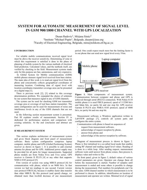
This section expla<strong>in</strong>s architecture <strong>of</strong> <strong>measurement</strong> <strong>system</strong><br />
and gives block diagram and front panel <strong>of</strong> <strong>measurement</strong><br />
s<strong>of</strong>tware. Basic <strong>system</strong> configuration comprises laptop<br />
computer, mobile phone and GPS (Global Position<strong>in</strong>g System)<br />
receiver as shown <strong>in</strong> figure 1. It is possible to add external<br />
antenna <strong>for</strong> phone and <strong>for</strong> GPS. Additional power supply may<br />
be provided <strong>for</strong> all parts <strong>for</strong> longer <strong>measurement</strong>s. Supported<br />
phone models are from Nokia 61xx and 51xx series. GPS<br />
receiver is Garm<strong>in</strong> II PLUS [4] or any other that supports<br />
NMEA 0183 protocol [5].<br />
First version <strong>of</strong> <strong>system</strong> was us<strong>in</strong>g MBUS protocol [6] <strong>for</strong><br />
communication with phone, which is on 9600 bit/s. In that<br />
version we had ten read<strong>in</strong>gs <strong>in</strong> one second. Current version<br />
uses protocol FBUS [6], because it enables faster data transfer<br />
than older MBUS. By this protocol (and speed) change, we<br />
obta<strong>in</strong>ed more than tw<strong>of</strong>old decrease <strong>of</strong> one <strong>measurement</strong><br />
period. One could expect much more but the limit<strong>in</strong>g factor is<br />
<strong>in</strong> our phone that can send new <strong>signal</strong> <strong>level</strong> every 35ms.<br />
NMEA<br />
4800 8N1<br />
Mobile phone<br />
FBUS 115200 8N1<br />
GPS receiver<br />
Laptop computer<br />
Figure 1. Ma<strong>in</strong> components <strong>of</strong> <strong>measurement</strong> <strong>system</strong>.<br />
Communication between computer and phone and GPS is<br />
achieved through serial (RS232) connection. With Nokia 6110<br />
mobile phone it is used FBUS protocol, speed <strong>of</strong> 115200 bit/s<br />
and 8data bits, no parity bit and one stop bit. GPS receiver<br />
Garm<strong>in</strong> II PLUS uses NMEA 0183 protocol, speed <strong>of</strong> 4800<br />
bit/s, no parity bit and one stop bit.<br />
Measurement s<strong>of</strong>tware, a W<strong>in</strong>dows application written <strong>in</strong><br />
LabVIEW package [7], controls all <strong>system</strong> parts and<br />
configures the entire <strong>system</strong>.<br />
Communication with phone is based on sequences <strong>of</strong>:<br />
- request from <strong>measurement</strong> s<strong>of</strong>tware,<br />
- acknowledge <strong>of</strong> request reception by phone,<br />
- answer from phone and<br />
- acknowledge <strong>of</strong> the answer reception by s<strong>of</strong>tware.<br />
Diagram <strong>of</strong> <strong>measurement</strong> process is shown <strong>in</strong> figure 2.<br />
Phone is first <strong>in</strong>itialized <strong>in</strong> a so-called local mode that enables<br />
sett<strong>in</strong>g RF channel and read<strong>in</strong>g <strong>signal</strong> <strong>level</strong> values. Read<strong>in</strong>g <strong>of</strong><br />
is done <strong>in</strong> a while loop. After send<strong>in</strong>g request, <strong>measurement</strong><br />
s<strong>of</strong>tware waits until answer from phone comes, then process it,<br />
displays value and writes to file.<br />
On front panel, given <strong>in</strong> figure 3, default values <strong>of</strong> various<br />
control parameters are given. Operator can change them all<br />
be<strong>for</strong>e the <strong>measurement</strong> is started. Number <strong>of</strong> samples until<br />
<strong>measurement</strong> is ended and some others is possible to change<br />
dur<strong>in</strong>g the <strong>measurement</strong>. Port numbers <strong>for</strong> peripherals can’t be<br />
the same. GSM channel number <strong>in</strong> which <strong>measurement</strong> is to be<br />
per<strong>for</strong>med is chosen. In addition, identification on location <strong>of</strong><br />
<strong>measurement</strong> and operator are written. M<strong>in</strong>imal <strong>level</strong> <strong>of</strong> <strong>signal</strong>
is set too. It can be chosen to do time-triggered <strong>measurement</strong><br />
with and without GPS localization.<br />
Write data to output<br />
files<br />
No<br />
No<br />
START<br />
Check the apparatus<br />
Problem?<br />
No<br />
Read-out and check<br />
data from phone and<br />
GPS<br />
Problem?<br />
End?<br />
Yes<br />
END<br />
Yes<br />
Yes<br />
Communication<br />
with operator<br />
Figure 2. Simplified block diagram <strong>of</strong> the<br />
<strong>measurement</strong> process controled by s<strong>of</strong>tware.<br />
Communication with GPS is simpler. Computer listens on<br />
GPS port and reads data. Accord<strong>in</strong>g to NMEA <strong>for</strong>mat data are<br />
divided, by GPS, <strong>in</strong> frames which are generated every two<br />
seconds. Each frame consists <strong>of</strong> 12 subframes <strong>in</strong> which are<br />
conta<strong>in</strong>ed many <strong>in</strong><strong>for</strong>mation <strong>for</strong> user.<br />
packet is 700 bytes long and can be transferred <strong>in</strong> about one<br />
second, which is per<strong>for</strong>med <strong>in</strong> consecutive read<strong>in</strong>gs, <strong>in</strong> time<br />
slots when wait<strong>in</strong>g answer from phone. For each frame is<br />
checked validity <strong>of</strong> location data because three or more<br />
satellites are needed <strong>for</strong> reliable position fix.<br />
From directly measured <strong>signal</strong> power <strong>level</strong> electrical field<br />
<strong>level</strong> can be found by <strong>for</strong>mula (1). Additive factor is dependent<br />
on frequency, antenna ga<strong>in</strong> and cable loss and <strong>for</strong> GSM<br />
<strong>measurement</strong>s it is about 140 dB.<br />
E [ dBµ V / m]<br />
= P [ dBmW ] + Add.<br />
factor [ dB]<br />
(1)<br />
Operator should put appropriate value <strong>for</strong> additive factor <strong>in</strong><br />
front panel and measured values would be converted to<br />
electrical field <strong>level</strong>, shown on graph, and put <strong>in</strong> file.<br />
III RESULTS<br />
All measured values are saved <strong>in</strong> two output files <strong>in</strong> ASCII<br />
<strong>for</strong>m suitable <strong>for</strong> further manipulation. In file *.mob <strong>signal</strong><br />
<strong>level</strong> <strong>in</strong> GSM channel is written, and <strong>in</strong> *.gps geographical<br />
coord<strong>in</strong>ates <strong>of</strong> <strong>measurement</strong> po<strong>in</strong>ts, where “*” denotes the<br />
same file name chosen by user. The correlation <strong>of</strong> two files is<br />
expla<strong>in</strong>ed <strong>in</strong> figures 4 and 5. In both files header and footer<br />
gives basic <strong>in</strong><strong>for</strong>mation <strong>of</strong> concrete <strong>measurement</strong>. If the<br />
position data are not available <strong>in</strong> *.gps file is written text “No<br />
satellites!”.<br />
File name:<br />
measure83.mob<br />
Date [mm/dd/yy]: 10/23/02<br />
Location:<br />
test location<br />
Operator:<br />
test operator<br />
Measurement started at: 06:29:46 PM<br />
GSM channel number: 83<br />
M<strong>in</strong>imal <strong>level</strong> [dBm]: -102.0<br />
Additive factor [dB]: 0.00<br />
Sample Value<br />
1 -54.5<br />
2 -54.4<br />
3 -54.1<br />
4 -54.3<br />
5 -54.6<br />
……………....<br />
29996 -53.3<br />
29997 -53.6<br />
29998 -53.1<br />
29999 -53.3<br />
30000 -53.2<br />
Figure 3. Front panel <strong>of</strong> <strong>measurement</strong> s<strong>of</strong>tware dur<strong>in</strong>g the<br />
test<strong>in</strong>g with real GSM <strong>signal</strong> and simulated GPS position. It is<br />
easy to use and very flexible <strong>for</strong> various computer<br />
configurations.<br />
We have used first subframe GPRMC (GPS and Transit<br />
Specific) from which localization data are extracted. Whole<br />
Date [mm/dd/yy]: 10/23/02<br />
Measurement ended at:<br />
06:55:01 PM<br />
Average meas. period [ms]: 49.89<br />
Figure 4. Start and end <strong>of</strong> output file measure83.mob with<br />
<strong>signal</strong> <strong>level</strong> values <strong>in</strong> 83 rd GSM channel. Note that average<br />
<strong>measurement</strong> period is near 50ms.
A case where valid data from GPS receiver is not available is<br />
rarely found. Possible loss <strong>of</strong> location data is <strong>in</strong> urban areas<br />
with many tall build<strong>in</strong>gs.<br />
File name:<br />
measure83.gps<br />
GPS position correction: latitude 0"<br />
longitude +20"<br />
Date [mm/dd/yy]: 10/23/02<br />
Measurement started at: 06:29:46 PM<br />
latitude longitude<br />
GPS mob<br />
1 40 45ø00'00.0"N 019ø41'35.0"E<br />
2 80 45ø00'00.0"N 019ø41'35.0"E<br />
3 120 45ø00'00.0"N 019ø41'35.0"E<br />
4 160 45ø00'00.0"N 019ø41'35.0"E<br />
5 199 45ø00'00.0"N 019ø41'35.0"E<br />
................................................................................<br />
767 29802 45ø00'00.0"N 019ø41'35.0"E<br />
768 29842 45ø00'00.0"N 019ø41'35.0"E<br />
769 29881 45ø00'00.0"N 019ø41'35.0"E<br />
770 29921 45ø00'00.0"N 019ø41'35.0"E<br />
771 29961 45ø00'00.0"N 019ø41'35.0"E<br />
Date [mm/dd/yy]: 10/23/02<br />
Measurement ended at:<br />
06:55:01 PM<br />
Figure 5. Output file measure83.gps with latitude and<br />
longitude values paired with <strong>signal</strong> <strong>level</strong> <strong>measurement</strong>s from<br />
file measure83.mob (number <strong>in</strong> second column). Localization<br />
data are same because GPS is <strong>in</strong> simulation mode.<br />
IV PERFORMANCE ANALYSIS<br />
M<strong>in</strong>imal period <strong>of</strong> <strong>measurement</strong> <strong>of</strong> GSM <strong>signal</strong> <strong>level</strong> can be<br />
adjusted to less than 50ms and depends on computer<br />
configuration. Coord<strong>in</strong>ates from GPS receiver are obta<strong>in</strong>ed on<br />
every 2 second. If the vehicle has speed <strong>of</strong> 20m/s (72km/h), the<br />
m<strong>in</strong>imal distance between successive <strong>measurement</strong>s <strong>of</strong> GSM<br />
<strong>signal</strong> is less than 1m and between two successively read<br />
positions is about 40m.<br />
For older computers average <strong>measurement</strong> time is <strong>in</strong>creas<strong>in</strong>g<br />
if graph is displayed on the screen and if sound <strong>signal</strong>izes<br />
lower <strong>level</strong> than settled limit. For this reasons it is possible to<br />
switch <strong>of</strong>f both dur<strong>in</strong>g <strong>measurement</strong>.<br />
Mobile phone does not have <strong>measurement</strong> speed <strong>of</strong> TS55-C3<br />
(Table 1.), but has smaller dimensions and mass. Measurement<br />
accuracy <strong>of</strong> <strong>system</strong>, <strong>in</strong>herited from phone, is better than 1dB,<br />
which is like <strong>in</strong> TS55-C3. Calibration can be achieved by<br />
procedure given <strong>in</strong> service manual <strong>for</strong> cellular phone [8].<br />
Table 1. Comparison <strong>of</strong> solutions <strong>for</strong> GSM <strong>signal</strong><br />
<strong>measurement</strong> by m<strong>in</strong>imal <strong>measurement</strong> time and frequency<br />
band.<br />
M<strong>in</strong>imal<br />
meas. time<br />
Band<br />
Our<br />
<strong>system</strong><br />
Anritsu<br />
ML521 A/B<br />
Rohde &<br />
Schwarz TS55-<br />
C3<br />
< 50ms 50ms 3ms<br />
GSM<br />
<strong>900</strong>/1800<br />
25MHz to<br />
1000MHz<br />
GSM <strong>900</strong>/1800<br />
V CONCLUSIONS<br />
Measurement <strong>system</strong> presented <strong>in</strong> this paper is realized on<br />
idea <strong>of</strong> effective <strong>signal</strong> <strong>level</strong> <strong>measurement</strong> <strong>in</strong> chosen GSM<br />
channel and test<strong>in</strong>g transmitter coverage by us<strong>in</strong>g available<br />
and simple <strong>measurement</strong> equipment. Us<strong>in</strong>g mobile phone as<br />
receiv<strong>in</strong>g unit it can be avoided use <strong>of</strong> complex <strong>measurement</strong><br />
receiver and <strong>signal</strong> <strong>level</strong> is detected by the very same receiver<br />
the user has. Collect<strong>in</strong>g geographic coord<strong>in</strong>ates from GPS<br />
enables coverage zone identification on digital map. Dur<strong>in</strong>g<br />
the test<strong>in</strong>g <strong>in</strong> laboratory <strong>system</strong> has shown expected reliability.<br />
Presented <strong>system</strong> is more flexible and cheaper <strong>in</strong> comparison<br />
with special ones but with higher <strong>measurement</strong> period.<br />
As <strong>system</strong> speed is limited by phone further work should be<br />
on speed<strong>in</strong>g up <strong>measurement</strong> by us<strong>in</strong>g other series <strong>of</strong> Nokia<br />
mobile phones. In addition, support <strong>for</strong> simultaneous<br />
<strong>measurement</strong> on two or three mobiles (channels) may be<br />
added, which is limited by number <strong>of</strong> serial ports on computer.<br />
REFERENCES<br />
[1] Gordana Zivanovic, Aleksandar Neskovic, Natasha<br />
Neskovic, George Paunovic, Process<strong>in</strong>g and Graphical<br />
Presentation <strong>of</strong> GSM Signal Level Measurements, TELFOR<br />
2000, Belgrade<br />
[2] Mirjana Simic, Rastko Zivanovic, Aleksandar Neskovic,<br />
George Paunovic, System <strong>for</strong> Automatic Electric Field Level<br />
Measurements with GPS Localization, TELFOR 2000,<br />
Belgrade<br />
[3] Rastko Zivanovic, Mirjana Simic, Aleksandar Neskovic,<br />
George Paunovic, Automated System <strong>for</strong> GSM Signal Level<br />
Measurement Us<strong>in</strong>g GPS Localization, TELFOR 2000,<br />
Belgrade<br />
[4] GPS II PLUS, Owner's Manual & Reference, GARMIN<br />
Corporation, 1997<br />
[5] NMEA 0183 Interface Standard, Version 2.30, National<br />
Mar<strong>in</strong>e Electronics Association, 1998<br />
[6] FBUS and MBUS protocol, http://www.gnokii.org<br />
[7] LabVIEW User Manual, National Instruments, 1998<br />
[8] Service manual <strong>for</strong> NOKIA cellular phones<br />
Acknowledgement: Measurement <strong>system</strong> is realized at<br />
Laboratory <strong>for</strong> radio-<strong>system</strong>s, Telecommunication department,<br />
Faculty <strong>of</strong> Electrical Eng<strong>in</strong>eer<strong>in</strong>g <strong>in</strong> Belgrade.<br />
Abstract: Ma<strong>in</strong> goal <strong>of</strong> this paper is presentation <strong>of</strong> a mobile,<br />
flexible and economical solution <strong>of</strong> automated <strong>system</strong> <strong>for</strong><br />
<strong>measurement</strong> <strong>of</strong> <strong>signal</strong> <strong>level</strong> <strong>in</strong> chosen GSM <strong>900</strong>/1800 channel.<br />
Measurement <strong>system</strong> comprises cellular phone and satellite<br />
radio-navigation <strong>system</strong> receiver connected to laptop<br />
computer. Full automatization <strong>of</strong> the <strong>measurement</strong> process is<br />
achieved by s<strong>of</strong>tware, implemented <strong>in</strong> LabVIEW s<strong>of</strong>tware<br />
package that controls and manages the <strong>system</strong>. Accuracy <strong>of</strong><br />
measured <strong>signal</strong> <strong>level</strong> is better than 1dB and <strong>measurement</strong><br />
period is less than 50ms. System is suitable <strong>for</strong> fieldwork and<br />
can be used <strong>in</strong> test<strong>in</strong>g coverage <strong>of</strong> transmitter or when<br />
check<strong>in</strong>g <strong>in</strong>terference <strong>level</strong>s. Comparison <strong>of</strong> our solution with<br />
exist<strong>in</strong>g solutions is also given.