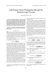
transmultiplexer-based multicarrier systems for powerline ... - Telfor
transmultiplexer-based multicarrier systems for powerline ... - Telfor
transmultiplexer-based multicarrier systems for powerline ... - Telfor

Create successful ePaper yourself
Turn your PDF publications into a flip-book with our unique Google optimized e-Paper software.
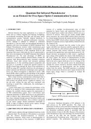
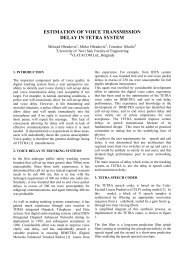
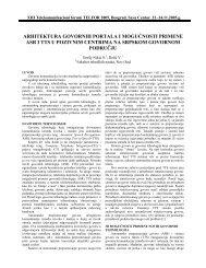
M-1 ... 1 0 0 1 ... M-1-π π 0 ππ−M Mρ=0.1...-π π 0 ππ−M M...ρ=1.1-π π 0 ππ−M MFrequencyFigure 1. Amplitude responses <strong>for</strong> the idealizedchannel filters using different values of ρ.than existing DFT-<strong>based</strong> <strong>systems</strong>. We can also adjust the subbandoverlapping.In TMUX <strong>systems</strong> the transmission channel is dividedinto M sub-channels with frequency spacing 1/2M using thebank of M sub-filters as shown in Figure 1. The rate of symbolsin sub-channel is 1/M. The phase and amplitude distortionsin the sub-channels and the interference between subchannelscan be controlled by properly designed sub-bandfilters. Phase distortion is eliminated if sub-band filters havecertain properties. The amplitude distortion produces Inter-Symbol Interference (ISI) in the receiver. Nyquist criterionmust be satisfied but if sub-channel equalizer is employedsome flexibility can be introduced. The aliasing distortion ofthe filter bank corresponds to Inter-Carrier Interference (ICI)or crosstalk in TMUX. The prototype filter can be designedwith the help of classical optimization techniques, but itslength N can be several thousands and a direct technique alsoseems appropriate [8].Key parameter in digital transmission is a delay. Overalldelay budget allotted to the system is shared among functionsin the transmitter and receiver. In single carrier transmissiondecoding and error correction uses most of the delay budget,but in MCM (especially filter bank <strong>based</strong>), modulation anddemodulation consume big part of the delay budget and thedelay of sub-band filters should be minimized. There<strong>for</strong>e,number of coefficients N is a trade-off between delay andfilter per<strong>for</strong>mance (especially stop-band attenuation) [8].Also, the computation of complexity is linearly related to thenumber of coefficients N and it should be decreased.Filter banks can be designed with the perfect reconstruction(PR) or nearly PR property (NPR). NPR filter banksallow some amount of ISI and/or ICI. However, an analogchannel between synthesis and analysis filters introducesdistortion and noise and in such a case PR should imply perfectequalization in the receiver which is unrealistic. There<strong>for</strong>eit is not necessary to examine PR filter banks [8]. However,it was shown in the literature that by allowing smallamplitude and aliasing distortions, the resulting NPR filterbank possesses a significantly improved stop-band per<strong>for</strong>mancecompared to the corresponding PR filter bank of thesame delay. Also those distortions to the signal can be muchsmaller than distortions caused by other reasons. If filters arewell derived, the maximum amplitude of the aliasing terms is......X 0 (z)guaranteed to be at most equal to the minimum stop-bandattenuation of the channel filters [7].In the following, we analyze the synthesis problem ofTMUX. A maximally decimated M-channel TMUX is shownin Figure 2. It consists of synthesis filter bank that containsM filters F m (z) and after the channel, in the receiver, is analysisfilter bank of M filters H m (z). There is a relationship betweenthose two filter banks if they satisfy PR condition. Inorder to simplify analysis we assume that the channel responseC(z) is equal to unity or to a pure delay.The output signals in the frequency domain can be expressedas follows:M 1 M My(z ) = T ( z ) ⋅ x(z ) , (1)Mwhereand↑MX 1 (z)↑M...X M-1 (z)↑M[ Y Y ] T0(z),...,M −( z[ X ( z),...,X ] TM( zy z ) =) , (2)(1x z ) =) , (3)(0 −1MM[ T ( z ) ] = ∑ −abF 0 (z)F 1 (z)F M-1 (z)1k = 0H ( zeaChannelC(z)=1H 0 (z)− j2π k / M − j2πk/ M) Fb( ze ) . (4)The matrix T(z M ) is so-called transfer matrix. Each elementof this matrix represents the relation between certain inputand corresponding output signal. The elements in the maindiagonal are the transfer functions of M sub-channels of thesystem, and other elements describe the cross-talk betweendifferent channels. In the case when TMUX is <strong>based</strong> on PRfilter bank, the transfer matrix is diagonal.MT ( z ) = diag[ S0(z),...,SM−1(z)], (5)where S i (z), i=0,1,…,M−1 are simple delays of the <strong>for</strong>m z -kMwith k being an integer. The amplitude distortion in theanalysis-synthesis configuration can be said to cause ISI inTMUX. Instead of aliasing distortion in other <strong>systems</strong>, theproblem in TMUX is ICI. The values of ISI and ICI can beestimated from the matrix T.Because we expect to have big number of sub-channels, ifwe use TMUX in PLC <strong>systems</strong>, one convenient way to designand implement TMUX is using cosine modulated filterbanks. We will explain this class of filter banks in the nextchapter.4. COSINE-MODULATED FILTER BANK,THEORY AND IMPLEMENTATION↓Msynthesis filters analysis filtersFigure 2. Maximally decimated M-channel TMUX.Y 0(z)H 1 (z) ↓M Y 1(z)...H M-1 (z) ↓MY M-1(z)Traditionally MCM can be implemented also using DiscreteWavelet MultiTone (DWMT) technique instead of DFT andit showes better per<strong>for</strong>mances. Hence, DWMT filter bank<strong>based</strong> system can be very frequency selective. Good way to
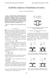
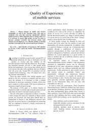
z -1...z -1...↓M↓M↓MPrototypefilteru(0)DCTu(M/2−1)u(M/2)Magnitude in dB50−5−10−15−20−25z -1↓Mu(M−1)Figure 3. General implementation of analysys filterbank structure with parallel CMFB.implement this type of filter bank is to use Cosine-modualtedfilter bank (CMFB). The basic idea of CMFB is that subchannelfilters can be derived from a single lowpassprototype filter, whose order is N and transition band is centeredon f c =1/4M, using cosine modulation. The prototypefilter controls the phase and amplitude distortions in the subchannelsand the interference between sub-channels. This isthe most effective technique to construct the desired analysisand synthesis filters from design and implementation point ofview. At the receiver, we need sine modualted filter bank(SMFB) [7].First step in designing the CMFB is to optimize theprototype filter whose transfer function H p (Z) has thefollowing <strong>for</strong>m:NH ( z)= h n z− n∑ ( ) . (6)ppn = 0Phase distortion is eliminated if the prototype filter has linearphase. The linear phase is achieved if the impulse response ofthe prototype filter is symmetric [7]:h ( N − n)= h ( n). (7)p pAlso, -3dB point of the amplitude response is at about ω =π/(2M) and stopband edge is given by( 1 + ρ)πω = , (8)s 2Mwhere ρ > 0 is the roll-off factor determing how much theadjacent channels are spectrally overlapped. In Figure 2 isshown that <strong>for</strong> 0 < ρ ≤ 1 only neighbouring channels on bothsides overlap; <strong>for</strong> 1 < ρ ≤ 2: two neigh-bouring channels onboth sides overlap; and it can be shown that <strong>for</strong> ρ > 2 at leastthree neighbouring channels on both sides overlap.After the prototype filter is designed, the sub-channelfilters <strong>for</strong> CMFB in general case can be expressed as:π Nh ( n)= 2h( n)cos((2k+ 1) ( n − ) + φ ) , (9)k p2M2 kandπ Nf ( n)= 2h( n)cos((2k+ 1) ( n − ) − φ ) , (10)k p2M2 kwhere Φ k = (−1) k π/4, k = 0,…, M−1, M is the number ofchannels and N is the lenght of the prototype filter. As can beseen, synthesis filters are time-reversed versions of theanalysis filters, i.e. f k (n) = h k (N−n) [7].The idea is to design NPR filter bank with smallamplitude distortions. In this case, prototype filter can bedesigned in the least mean square sence. There<strong>for</strong>e we shouldfind the coefficients of H p (z) to minimizesubject toand−30−35−400 0.05 0.1 0.15 0.2 0.25 0.3 0.35 0.4 0.45 0.5Frequency in F sFigure 4. Frequence response of DFT <strong>based</strong> MCMsystem.= π jωE2 H p ( e ) dω(11)ω∫s[ 0, π ]jω− δ1 ≤ T 0(e ) ≤1+ δ , ω ∈(12)1 1[ 0, π ]jωT ( ) ≤ δ1,ω ∈(13)i e<strong>for</strong> i = 1, …, M − 1. The parameters δ 1 and δ 2 are constraintsthat define the maximum allowable amplitude distortion andaliasing distortion of the filter bank, respectively. [7]In filter banks with small amplitude distortion aliasingdistortions are not consdireded in the opimization ofprototype filter and the powers of the interferencecomponents can be estimated using <strong>for</strong>mulas:⎛2 ⎞ISI = max⎜∑( δ ( n)− tk( n))⎟ , (14)k ⎝ n⎠and⎛ M⎞= ⎜ ∑ − 12jω ICI max T ( e )⎟ . (15)k⎝ l = 0, k ≠lkl⎠It has been shown that the attenuation of the higheststopband ripple comparing to PR case has been improved atthe expense of small ISI and ICI. It was also noticed that <strong>for</strong>1 < ρ the stopband attenuation can be well improved, but <strong>for</strong>1 > ρ it can not be improved so much [7].In more generalized NPR filter banks, both constraints δ 1and δ 2 are specified. We can try to construct TMUX systemwith very low ICI level, but if it is too small, the attenuationof the highest stop-band ripple decreases. [7]These interference components of Error! Not a validlink. and Error! Not a valid link. are added to the channelnoise and they <strong>for</strong>m the total amount of distortions. Togetherthey influence on the bit error rate (BER). In order to achievedesired BER we have to find the maximum value of numberof sub-channels M max , which also depends on channel conditions.This will be considered in our future work.One way of CMFB implementation is parallelimplementation [9] shown in Figure 3. It consists of
Magnitude in dB0−20−40−60−80−100−1200 0.05 0.1 0.15 0.2 0.25 0.3 0.35 0.4 0.45 0.5Frequency in F sFigure 5. Frequence response <strong>for</strong> the prototype filterof CMFB.Magnitude in dB0−20−40−60−80−100−1200 0.05 0.1 0.15 0.2 0.25 0.3 0.35 0.4 0.45 0.5Frequency in F sFigure 6. Frequence responses <strong>for</strong> the sub-band filtersin CMFB.prototype filter and DCT block. Number of operartionscompared to the general filter bank is reduced. For easierequalization, CMFB can be implemented using parallel DCTand DST [9].5. DESIGN EXAMPLESIn this section we illustrate the advantages of usingTMUX instead of DFT in MCM and we give some numericalexamples <strong>for</strong> the explained CMFB.It is requiered to construct MCM of M = 8 channels. First,we can use conventional DFT <strong>based</strong> system. The sub-channelfrequency response <strong>for</strong> this case is given in Figure 4. It canbe noticed that side-lobes in stop-band are rather high.We can use also TMUX <strong>based</strong> MCM system describedabove. The prototype filter is designed using least sqaremethod (Kaiser window approach [10]) with maximumallowable stop-band ripple of As=60 dB. Sub-bandoverlappiong factor ρ is equal to unity. The length of theprototype filter N = 66 and its frequence response is shown inFigure 5. In Figure 6 where is shown the frequence responseof CMFB with M=8 channels, can be seen that attenuation instop-band is at least 60 dB. The way of controling stop-bandattenuation in TMUX is obvious. We can estimate ISI andICI using Equations (16) and (17).6. CONCLUSIONAs we have seen ADSL system encounters similarproblems as PLC system, what is shown in this paper. Thuswe show that NPR CMFB approach <strong>for</strong> highly selectivemaximally decimated TMUX <strong>systems</strong> is good solution <strong>for</strong>very frequency selective PLC system. We explained thatfilter bank characteristics can be improved by allowing smallISI and ICI and that stop-band ripples can be well and easycontroled. We have also illustrated per<strong>for</strong>marance of NPRCMFB which will be used in our future research. Our aim isto show that TMUX <strong>based</strong> MCM is good option <strong>for</strong> PL<strong>systems</strong>.REFERENCES[1] Patrick J. Langfeld, Klaus Dostert, OFDM System Synchronization<strong>for</strong> Powerline Communications, Karlsruhe, Germany.[2] Kazutoshi Sugimoto, Masaaki Katayama, Takaya Yamazato andHiraku Okada, Per<strong>for</strong>mance of an OFDM Communication Systemunder Frequency and Time Dependent Power-Line Channel.[3] Bojana Bajić, Đorđe Babić, Pregled sistema za prenos podatakai brzi pristup internetu elektroenergetskom mrežom, Tel<strong>for</strong>2002.[4] Bojana Bajić, Đorđe Babić, Modulacije sa višestrukimnosiocima u PL sistemima.[5] Geramny Jeroen Van den Keybus, Bruno Bolsens, JohanDriesen and Ronnie Belmans, PowerLine CommunicationFront-Ends Based on ADSL technology, Belgium.[6] Eric Lawrey, Thesis COFDM as a modulation technique <strong>for</strong>wireless telecommunications, with a CDMA comparison, 1997.[7] Ari Viholainen, Tapio Saramaki and Marku Ren<strong>for</strong>s, NearlyPerfect-Reconstruction Cosine-Modulated Filter Bank Design<strong>for</strong> VDSL Modems, Tampere, Finland.[8] Maurice G. Bellanger, Specification and Design of a PrototypeFilter <strong>for</strong> Filter Bank Based Multicarrier Transmission, Paris,France.[9] Ari Viholainen, Juuso Alhava and Marku Ren<strong>for</strong>s, Implementationof parallel cosine and sine modulated filter banks <strong>for</strong> equalized<strong>transmultiplexer</strong> <strong>systems</strong>, Tampere, Finland.[10]Y-P. Lin and P. P. Vaidyanathan, “A Kaiser window approach<strong>for</strong> the design of prototype filters of cosine modulated filterbanks'', IEEE Signal Proc. Letters, vol. 5, 1998.Abstract: In this paper we gave a basic theory andimplementation of one, non-traditional approach to<strong>multicarrier</strong> <strong>systems</strong>. It was shown that filter bank <strong>based</strong><strong>systems</strong> can be considered as <strong>multicarrier</strong> <strong>systems</strong> with faraway better stop-band attenuation than <strong>multicarrier</strong> <strong>systems</strong><strong>based</strong> on DFT. We presented cosine modulated filter bankand showed that stop-band attenuation can be well controled.That feature is very useful in frequence selective channels asit is medium in ADSL <strong>systems</strong> and in very similar PLC<strong>systems</strong>. The aim of our future work is to implement<strong>transmultiplexer</strong> <strong>systems</strong> in PLC system and prove itssuitability <strong>for</strong> this case.SISTEMI SA VIŠE NOSILACA ZASNOVANI NATRANSMULTIPLEKSERIMA ZA PLC KANAL, BojanaBajic, Djordje Babic.