estimation of voice transmission delay in tetra system - Telfor
estimation of voice transmission delay in tetra system - Telfor
estimation of voice transmission delay in tetra system - Telfor

You also want an ePaper? Increase the reach of your titles
YUMPU automatically turns print PDFs into web optimized ePapers that Google loves.
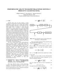
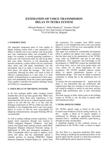
ESTIMATION OF VOICE TRANSMISSIONDELAY IN TETRA SYSTEMMilorad Obradović 1 , Mirko Obradović 2 , Tomislav Nikolić 21 University <strong>of</strong> Novi Sad, Faculty <strong>of</strong> Eng<strong>in</strong>eer<strong>in</strong>g2 VLATACOM Ltd., Belgrade1. INTRODUCTIONThe important component parts <strong>of</strong> <strong>voice</strong> quality <strong>in</strong>digital trunk<strong>in</strong>g <strong>system</strong> from a user perspective are:ability to identify user (<strong>voice</strong> clarity); call set-up <strong>delay</strong>and <strong>voice</strong> <strong>transmission</strong> <strong>delay</strong> (not acceptable if toolarge). For example, <strong>in</strong> normal operat<strong>in</strong>g conditions, apolice user will consciously allow for call set-up <strong>delay</strong>and <strong>voice</strong> <strong>delay</strong>. However, <strong>in</strong> life threaten<strong>in</strong>g andstressful situations, a police <strong>of</strong>ficer will not consciouslyallow <strong>delay</strong> and will speak immediately <strong>in</strong>to themicrophone and if no reply is received after a veryshort pause, will repeat the message. This lack <strong>of</strong>consciously allow<strong>in</strong>g for <strong>delay</strong> will result <strong>in</strong> lack <strong>of</strong>effective communications at a time when it is mostneeded. If dissatisfaction is experienced <strong>in</strong> these areas,users will undoubtedly deem the <strong>system</strong> unacceptable.Voice quality is therefore the greatest challenge fac<strong>in</strong>gall TETRA [1] manufacturers.2. VOICE DELAY IN TRUNKING SYSTEMSIn the first analogue public safety trunk<strong>in</strong>g <strong>system</strong>founded that call set up times greater than 700ms wereunacceptable. S<strong>in</strong>ce those early experiences, it hasdeterm<strong>in</strong>ed that call set up <strong>in</strong> a typical regional scenarioneeds to be sub 400 ms; this is <strong>in</strong> l<strong>in</strong>e with theSchengen requirement <strong>of</strong> 300 ms with<strong>in</strong> one radio site.Similarly, it was founded that end to end <strong>voice</strong> packet<strong>delay</strong>s <strong>in</strong> excess <strong>of</strong> 500 ms were unacceptable fortalkgroup communications; and aga<strong>in</strong> better<strong>in</strong>g 400 mswas preferable.As well as analog trunk<strong>in</strong>g <strong>system</strong>s experience, it hasga<strong>in</strong>ed much experience through user reaction toTDMA <strong>in</strong>tegrated Dispatch, Telephony and Data<strong>system</strong>, first digital radio trunk<strong>in</strong>g <strong>system</strong>, called IDEN(Integrated Dispatch Enhanced Network) dur<strong>in</strong>g itsdeployment <strong>in</strong> 1995, and subsequent acceptance <strong>in</strong>1996. Considerable effort was made to improve <strong>voice</strong>clarity and <strong>delay</strong>, and has undoubtedly placed avaluable position <strong>in</strong> ensur<strong>in</strong>g DIMETRA (DigitalMotorola Enhanced Trunked Radio) [3] learns fromthis experience. For example, from IDEN <strong>system</strong>operation, it was founded that end to end <strong>voice</strong> packet<strong>delay</strong>s <strong>in</strong> excess <strong>of</strong> 250 ms were unacceptable for fullduplex telephone <strong>in</strong>terconnect.This aga<strong>in</strong> was rectified by considerable developmenteffort to optimise the digital <strong>voice</strong> coder, experiencethat has been used <strong>in</strong> the optimisation <strong>of</strong> the TETRA<strong>voice</strong> coder on DIMETRA and end to end <strong>delay</strong>performance. This experience and knowledge <strong>in</strong> thedevelopment <strong>of</strong> DIMETRA <strong>system</strong> has identified thatcall set-up times, end to end <strong>voice</strong> packet <strong>delay</strong> and<strong>voice</strong> clarity are <strong>of</strong> prime importance for useracceptance. The TETRA standard imposes certa<strong>in</strong><strong>delay</strong>s <strong>in</strong> speech <strong>transmission</strong> because <strong>of</strong> itsfundamental design. This must be added to practicalconstra<strong>in</strong>ts <strong>in</strong> tim<strong>in</strong>g due to the underly<strong>in</strong>g laws <strong>of</strong>physics.To achieve the user requirements for speech and call<strong>delay</strong>, it was determ<strong>in</strong>ed that any architecture thatrequired more than two switches to set up and carry acall would be unlikely to satisfy its end users; and thisdictated high performance peer to peer network<strong>in</strong>gdesign.The ma<strong>in</strong> reasons <strong>of</strong> <strong>delay</strong> which exists <strong>in</strong> the trunk<strong>in</strong>g<strong>system</strong>, as TETRA is, are: the <strong>delay</strong> <strong>in</strong> speech coderand <strong>transmission</strong> <strong>delay</strong>.3. TETRA SPEECH CODERThe TETRA speech codec is based on the Code-Excited L<strong>in</strong>ear Predictive (CELP) cod<strong>in</strong>g model [2]. Inthis model, a block <strong>of</strong> N speech samples issynthesized by filter<strong>in</strong>g an appropriate <strong>in</strong>novationsequence from a codebook, scaled by a ga<strong>in</strong> factor g c,through two time vary<strong>in</strong>g filters.A simplified diagram <strong>of</strong> this synthesis process, asimplemented <strong>in</strong> the TETRA codec, is shown <strong>in</strong> figure1.The first filter is a long-term prediction filter (pitchfilter) aim<strong>in</strong>g at model<strong>in</strong>g the pseudo-periodicity <strong>in</strong> thespeech signal and the second is a short-term predictionfilter model<strong>in</strong>g the speech spectral envelope.
where T is the pitch <strong>delay</strong> and g p is the pitch ga<strong>in</strong>. Thepitch synthesis filter is implemented as an adaptivecodebook, where for <strong>delay</strong>s less than the sub-framelength the past excitation is repeated.The short-term synthesis filter is given by:1 1H ( z)= =, (2)pA(z)−i1+a z i∑i=1Figure1. The synthesis processThe long-term or pitch, synthesis filter is given by:where a i, i = 1,........, p, are the L<strong>in</strong>ear Prediction (LP)parameters and p is the predictor order. In theTETRA codec p = 10.1B ( z )1=1 − g z p−T, (1)InputSpeechUnquantizedLPC <strong>in</strong>foLPC ANALYSISQUANTIZATION &INTERPOLATIONPastExcitationT0OPEN LOOPPITCHANALYSISPERCEPTUALWEIGHTINGTADAPTIVECODEBOOKgpgcLPC <strong>in</strong>foSHORT-TERMSYNTHESISFILTERkALGEBRAICCODEBOOKMSESEARCHPERCEPTUALWEIGHTINGGAIN VQGa<strong>in</strong>sPitch <strong>delay</strong> (T)Codebook <strong>in</strong>dex (k)LPC <strong>in</strong>foMULTIPLEXDigitalOutputFigure 2. Block diagram <strong>of</strong> the TETRA speech coder
The TETRA encoder uses an analysis-by-synthesistechnique to determ<strong>in</strong>e the pitch and excitationcodebook parameters.In this analysis-by-synthesis technique, the syntheticspeech is computed for all candidate <strong>in</strong>novationsequences reta<strong>in</strong><strong>in</strong>g the particular sequence thatproduces the output closer to the orig<strong>in</strong>al signalaccord<strong>in</strong>g to a perceptually weighted distortionmeasure.The perceptual weight<strong>in</strong>g filter de-emphasizes the errorat the formant regions <strong>of</strong> the speech spectrum and isgiven by:A(z)W ( z)= , (3)A(z / γ )where A(z) is the LP <strong>in</strong>verse filter and 0
layers, the physical and the l<strong>in</strong>k layer. It provides errordetection, but no error correction. Because <strong>of</strong> this, thenetwork buffer<strong>in</strong>g requirements are reduced, hence the<strong>in</strong>crease <strong>in</strong> throughput. Instead, the element <strong>of</strong> the<strong>system</strong> that guarantees the error-free end-to-endtransfer <strong>of</strong> frames are the endpo<strong>in</strong>t devices, not thenetwork itself. This protocol process<strong>in</strong>g, which is stillnecessary to guarantee the accurate delivery <strong>of</strong> thedata, is left to the higher layers <strong>in</strong>herent <strong>in</strong> thetransported data. The frame relay <strong>in</strong>terfacespecification provides a signal<strong>in</strong>g and data transfermechanism between endpo<strong>in</strong>ts and the network. This<strong>in</strong>terface allows communication bandwidth to beshared among multiple users, creat<strong>in</strong>g <strong>in</strong>stantaneousbandwidth allocation on demand. Each frame (orpacket) conta<strong>in</strong>s header <strong>in</strong>formation that is used todeterm<strong>in</strong>e the rout<strong>in</strong>g <strong>of</strong> the data to the desireddest<strong>in</strong>ation. This enables each endpo<strong>in</strong>t tocommunicate with multiple dest<strong>in</strong>ations via a s<strong>in</strong>gleaccess l<strong>in</strong>k to the network. Instead <strong>of</strong> fixed amounts <strong>of</strong>bandwidth allocated to the resource, frame relay trafficreceives full bandwidth for short transaction bursts.Frame Relay uses the synchronous HDLC frameformat up to 4 kbytes <strong>in</strong> length. Each frame starts andends with a Flag character (7E Hex). The first 2 bytes<strong>of</strong> each frame follow<strong>in</strong>g the flag conta<strong>in</strong> the<strong>in</strong>formation required for multiplex<strong>in</strong>g across the l<strong>in</strong>k,DLCI Field - Data L<strong>in</strong>k Connection Identifiers. Thelast 2 bytes <strong>of</strong> the frame are always generated by aCyclic Redundancy Check (CRC) <strong>of</strong> the rest <strong>of</strong> thebytes between the flags, known as a frame checksequence (FCS).The rest <strong>of</strong> the frame conta<strong>in</strong>s the userdata. FRFPS, as bearer protocol, enables good end toend <strong>voice</strong> packet <strong>delay</strong> performance.Abstracts: This paper considers the <strong>estimation</strong> <strong>of</strong><strong>voice</strong> <strong>transmission</strong> <strong>delay</strong> <strong>in</strong> digital trunk<strong>in</strong>g radio<strong>system</strong> TETRA. The ma<strong>in</strong> reasons <strong>of</strong> <strong>delay</strong> whichexists <strong>in</strong> the trunk<strong>in</strong>g <strong>system</strong>, as TETRA is, are: the<strong>delay</strong> <strong>in</strong> speech coder and <strong>transmission</strong> <strong>delay</strong>. The<strong>delay</strong> <strong>of</strong> speech coder is about 80 ms. TETRA hasadvantage <strong>of</strong> Frame Relay Fast Packet Switch<strong>in</strong>g , sshort packet <strong>delay</strong> and m<strong>in</strong>imal process<strong>in</strong>g to meet thetim<strong>in</strong>g requirement for real time <strong>voice</strong>communications. FRFPS, as bearer protocol, enablesgood end to end <strong>voice</strong> packet <strong>delay</strong> performance.Regarded to this protocol time <strong>delay</strong> <strong>in</strong> <strong>transmission</strong> isconsiderable less compared with speech coder <strong>delay</strong>.Accord<strong>in</strong>g to those pr<strong>in</strong>ciples, time <strong>delay</strong> is not largeand DIMETRA <strong>system</strong> has a satisfactory speechquality.REFERENCES[1] "Trans-European Trunk<strong>in</strong>g Radio (TETRA)",ETSI, 1996.[2] A. Gersho, "Advances <strong>in</strong> Speech and AudioCompression", Proceed. <strong>of</strong> IEEE, No. 6, June 1994.[3] "Dimetra-System Planer", MOTOROLA, 1998.[4] M. Obradović i dr., "Povezivanje baznih stanica usistem kod digitalnih mobilnih trank<strong>in</strong>gsistema",JUKO CIRED,Herceg Novi, 2000.Regarded to this protocol time <strong>delay</strong> <strong>in</strong> <strong>transmission</strong> isconsiderable less compared with speech coder <strong>delay</strong>and call set-up is less than 300 ms.5. CONCLUSIONRecognis<strong>in</strong>g the importance <strong>of</strong> <strong>voice</strong> quality <strong>in</strong> digitalradio trunk<strong>in</strong>g <strong>system</strong>, it is necessary detailedevaluation <strong>of</strong> the follow<strong>in</strong>g:• supplier experience <strong>in</strong> CELPC and network <strong>delay</strong>optimisation,• <strong>system</strong> design configuration for optimum call setupperformance,• <strong>system</strong> design configuration for optimum end toend <strong>voice</strong> packet <strong>delay</strong> performance, and• chosen bearer circuit end to end <strong>delay</strong>performance.Accord<strong>in</strong>g to those pr<strong>in</strong>ciples, time <strong>delay</strong> is not lageand DIMETRA <strong>system</strong> has a satisfactory speechquality.