Quantum Dot Infrared Photodetector - Telfor
Quantum Dot Infrared Photodetector - Telfor
Quantum Dot Infrared Photodetector - Telfor

You also want an ePaper? Increase the reach of your titles
YUMPU automatically turns print PDFs into web optimized ePapers that Google loves.
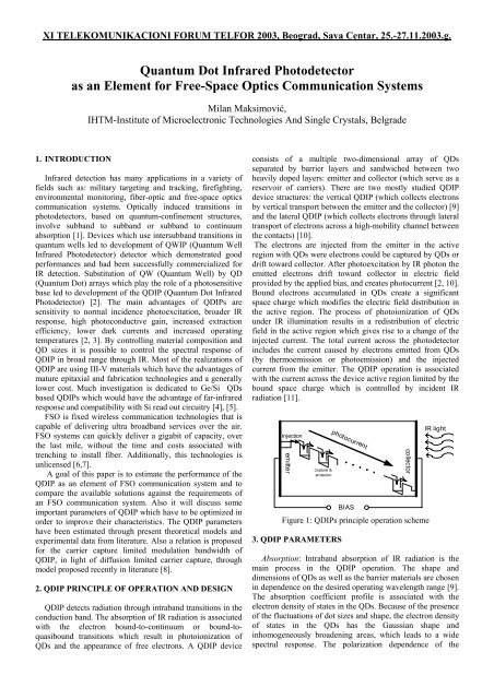
XI TELEKOMUNIKACIONI FORUM TELFOR 2003, Beograd, Sava Centar, 25.-27.11.2003.g.<strong>Quantum</strong> <strong>Dot</strong> <strong>Infrared</strong> <strong>Photodetector</strong>as an Element for Free-Space Optics Communication SystemsMilan Maksimović,IHTM-Institute of Microelectronic Technologies And Single Crystals, Belgrade1. INTRODUCTION<strong>Infrared</strong> detection has many applications in a variety offields such as: military targeting and tracking, firefighting,environmental monitoring, fiber-optic and free-space opticscommunication systems. Optically induced transitions inphotodetectors, based on quantum-confinement structures,involve subband to subband or subband to continuumabsorption [1]. Devices which use intersubband transitions inquantum wells led to development of QWIP (<strong>Quantum</strong> Well<strong>Infrared</strong> <strong>Photodetector</strong>) detector which demonstrated goodperformances and had been successfully commercialized forIR detection. Substitution of QW (<strong>Quantum</strong> Well) by QD(<strong>Quantum</strong> <strong>Dot</strong>) arrays which play the role of a photosensitivebase led to development of the QDIP (<strong>Quantum</strong> <strong>Dot</strong> <strong>Infrared</strong><strong>Photodetector</strong>) [2]. The main advantages of QDIPs aresensitivity to normal incidence photoexcitation, broader IRresponse, high photoconductive gain, increased extractionefficiency, lower dark currents and increased operatingtemperatures [2, 3]. By controlling material composition andQD sizes it is possible to control the spectral response ofQDIP in broad range through IR. Most of the realizations ofQDIP are using III-V materials which have the advantages ofmature epitaxial and fabrication technologies and a generallylower cost. Much investigation is dedicated to Ge/Si QDsbased QDIPs which would have the advantage of far-infraredresponse and compatibility with Si read out circuitry [4], [5].FSO is fixed wireless communication technologies that iscapable of delivering ultra broadband services over the air.FSO systems can quickly deliver a gigabit of capacity, overthe last mile, without the time and costs associated withtrenching to install fiber. Additionally, this technologies isunlicensed [6,7].A goal of this paper is to estimate the performance of theQDIP as an element of FSO communication system and tocompare the available solutions against the requirements ofan FSO communication system. Also it will discuss someimportant parameters of QDIP which have to be optimized inorder to improve their characteristics. The QDIP parametershave been estimated through present theoretical models andexperimental data from literature. Also a relation is proposedfor the carrier capture limited modulation bandwidth ofQDIP, in light of diffusion limited carrier capture, throughmodel proposed recently in literature [8].2. QDIP PRINCIPLE OF OPERATION AND DESIGNQDIP detects radiation through intraband transitions in theconduction band. The absorption of IR radiation is associatedwith the electron bound-to-continuum or bound-toquasiboundtransitions which result in photoionization ofQDs and the appearance of free electrons. A QDIP deviceconsists of a multiple two-dimensional array of QDsseparated by barrier layers and sandwiched between twoheavily doped layers: emitter and collector (which serve as areservoir of carriers). There are two mostly studied QDIPdevice structures: the vertical QDIP (which collects electronsby vertical transport between the emitter and the collector) [9]and the lateral QDIP (which collects electrons through lateraltransport of electrons across a high-mobility channel betweenthe contacts) [10].The electrons are injected from the emitter in the activeregion with QDs were electrons could be captured by QDs ordrift toward collector. After photoexcitation by IR photon theemitted electrons drift toward collector in electric fieldprovided by the applied bias, and creates photocurrent [2, 10].Bound electrons accumulated in QDs create a significantspace charge which modifies the electric field distribution inthe active region. The process of photoionization of QDsunder IR illumination results in a redistribution of electricfield in the active region which gives rise to a change of theinjected current. The total current across the photodetectorincludes the current caused by electrons emitted from QDs(by thermoemission or photoemission) and the injectedcurrent from the emitter. The QDIP operation is associatedwith the current across the device active region limited by thebound space charge which is controlled by incident IRradiation [11].injectionemittercapture &emissionphotocurrentBIAScollectorFigure 1: QDIPs principle operation scheme3. QDIP PARAMETERSIR lightAbsorption: Intraband absorption of IR radiation is themain process in the QDIP operation. The shape anddimensions of QDs as well as the barrier materials are chosenin dependence on the desired operating wavelength range [9].The absorption coefficient profile is associated with theelectron density of states in the QDs. Because of the presenceof the fluctuations of dot sizes and shape, the electron densityof states in the QDs has the Gaussian shape andinhomogeneously broadening areas, which leads to a widespectral response. The polarization dependence of the
XI TELEKOMUNIKACIONI FORUM TELFOR 2003, Beograd, Sava Centar, 25.-27.11.2003.g.absorption spectra has been established by theoretical modelsand experiment [12]. The strong normal incidence absorptionis connected with the QDs size, and the conclusion is that theQDs have to be small in the lateral and in the growthdirection [12].A good performance detector must have high absorptionefficiency and requires a high dot density. For the highestpossible absorption QDs the ground states have to be filledwith electrons, so it is customary to use the modulationdoping of the structure. The QDIPs with a bound-tocontinuumdetection scheme have a cut-off frequency definedby relationship [3]:QDIP hcEa= (1)λcwhere E a is the activation energy and equals the differencebetween the top of the barrier and the Fermi level in the QD,h is Planck constant and c is the speed of light. Anothernoticeable feature of the detection response spectra is thebroad line width ∆ λ which is much greater than in the caseλof QWIPs [2]. This aspect is useful for FSO applicationsbecause of the wavelength shift caused by the scatteringevents during propagation through air.Dark current: The dark current in photodetector is defined asthe current which flows across the device withoutillumination. In QDIPs it has generation-recombination originin the carrier trapping and thermionic emission from QDs andthermionic emission from emitter in the active region ofdevice [2]. QDIPs are expected to have lower dark currentsdue to the decrease of thermionic emission which isassociated with the effects on carrier capturing probabilityand the effective lifetime of carriers and effects such as:phonon bottleneck in electron capture (interlevel spacing inQDs is larger than the phonon energy), limitation in capturingprocess due to the Paulie principle, the presence of repulsivepotential barriers surrounding the charged QDs and QDssizes. The relationship which provides an estimate of thethermal dark current is [11]eGthjth≅ (2)pcwhere e is the electron charge, G th is the rate ofthermoemission per unit area of QDs layer and p c is theaverage capture probability for free electrons passing above aQD. A detailed theoretical consideration of dark current inQDIP leads to the conclusion that the dark currentoptimization depends on the following parameters: density ofQDs in QD layer, doping level of the active region, andapplied bias [13].Photocurrent and photoconductive gain: If QDIP is under IRillumination, which causes the photoexcitation of QDs due tothe bound-to-continuum transitions, the photoemissiondominates thermoemission and gives rise to the photocurrentwhich is estimated by the expression [11]eG ph eσQD < n > Φj ph = =( 3)pcpcorj ∝ eσ < n > Φg(4)phQDwhereG ph is the rate of photoemission per unit area of theQD layer, σ QD is the photoemission cross section (whichequals the absorption cross section under the principle ofdetailed balance!), is the average sheet density ofelectrons in the QD layer, Φ is the incident photons flux and gis the photoconductive gain. A very important parameter ofthe QDIP is the photoconductive gain defined as the ratio ofthe total flux of injected electrons to the total rate ofthermoemission (under dark conditions) or photoemission(under illumination) from all QDs. Under this definition wehave an expression, similar to those developed for QWIPs, inthe form [12,14]:1g ≈ M F p c (1 + p c )(5)where M is the number of QD layers, F is the filling factordetermining the portion of the covering area of the QD layerby QDs. This expression is valid under the condition p c R =≈(7)hωΦhωpcwhere h ω is the energy of incident photon. Responsivity ofQDIP can be as large as several A/W [11]. But it is importantthat although the responsivity is high and rises with biasvoltage, we also have an increase of the dark current, so thisis an issue for further optimization.Detectivity: Detectivity is a measure of SNR (signal-to-noiseratio)and it can be expressed by relation [2]:D*= RA∆fIntr= RA∆f4egIwhere A is the detector active area, ∆f is the measurementbandwidth, I n is noise current (which is in photoconductivemode expressed through shot noise). We can see thatlowering dark current leads to increase of detectivity.However, if we express detectivity in terms of totalthermoemission G th and photoemission G ph rates [11]:G* phD =hωΦ Gth∝N σQDNQDth∆f⎛ εa⎞< n > exp⎜⎟⎝ kT ⎠(8)(9)