Installation guide - Kele
Installation guide - Kele
Installation guide - Kele

Create successful ePaper yourself
Turn your PDF publications into a flip-book with our unique Google optimized e-Paper software.
L35 Series<br />
<strong>Installation</strong> Guide<br />
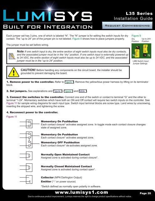
Each jumper set has 3 pins, one of which is labeled “N”. The “N” jumper is for setting the switch inputs for dry<br />
contact. The “up to 24” pin of the jumper pin is not labeled. Figure 9 shows how to place jumpers properly.<br />
The jumper must be set before wiring.<br />
Figure 9<br />
Dry<br />
Position<br />
Up to 24V<br />
Position<br />
Note If one switch input is dry, the entire section of eight switch inputs must also be dry contacts,<br />
and the associated jumper must be in the “dry” position. If one switch input is externally powered up<br />
to 24 VDC, the entire section of eight switch inputs must also be up to 24 VDC, and the associated<br />
jumper must be in the “up to 24” position.<br />
LMB Switch Input<br />
Jumper Settings<br />
CAUTION! Before handling any components on the circuit board, the installer should be<br />
grounded to prevent damaging the board.<br />
1. Remove power to the controller. Refer to Figure 4. Remove the yellow/blue power harness by lifting on its terminator<br />
block.<br />
2. Set jumpers. See explanations and Figure 8, Figure 9 and Table 1.<br />
3. Connect the switches to the controller. Connect one end of the switch or contact to terminal “G” and the other to<br />
terminal “1-24”. Momentary switches which have both an ON and Off contact will require two switch inputs on the controller. See<br />
Figure 11 for sample wiring diagrams for each input type. Switch input terminal blocks are screw type. Land wires by unscrewing,<br />
inserting the stripped wire, and tightening the screw.<br />
4. Reconnect power to the controller.<br />
Figure 11<br />
Momentary On Pushbutton<br />
Each contact closure* activates assigned zone. In toggle mode each contact closure changes<br />
state of assigned zone.<br />
Momentary On Pushbutton<br />
Each contact closure* activates assigned zone.<br />
Momentary OFF Pushbutton<br />
Each contact closure* de-activates assigned zone.<br />
Normally Open Maintained Contact<br />
Assigned zone is activated during contact closure*.<br />
Normally Closed Maintained Contact<br />
Assigned zone is activated during contact open*.<br />
E<br />
Collector (NPN Darlington Output)<br />
Emitter (“-” on power source)<br />
*Switch defined as normally open polarity in software.<br />
www.lumisys1.com<br />
Due to continuous product improvement, Lumisys reserves the right to change product specifications without notice.<br />
Page 20