Installation guide - Kele
Installation guide - Kele
Installation guide - Kele

You also want an ePaper? Increase the reach of your titles
YUMPU automatically turns print PDFs into web optimized ePapers that Google loves.
L35 Series<br />
<strong>Installation</strong> Guide<br />
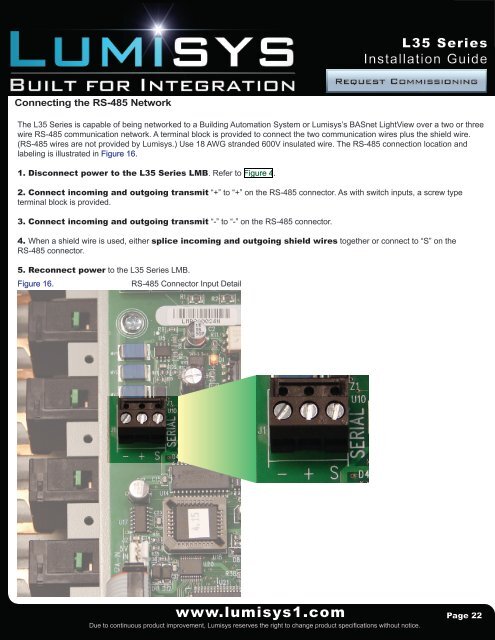
Connecting the RS-485 Network<br />
The L35 Series is capable of being networked to a Building Automation System or Lumisys’s BASnet LightView over a two or three<br />
wire RS-485 communication network. A terminal block is provided to connect the two communication wires plus the shield wire.<br />
(RS-485 wires are not provided by Lumisys.) Use 18 AWG stranded 600V insulated wire. The RS-485 connection location and<br />
labeling is illustrated in Figure 16.<br />
1. Disconnect power to the L35 Series LMB. Refer to Figure 4.<br />
2. Connect incoming and outgoing transmit “+” to “+” on the RS-485 connector. As with switch inputs, a screw type<br />
terminal block is provided.<br />
3. Connect incoming and outgoing transmit “-” to “-” on the RS-485 connector.<br />
4. When a shield wire is used, either splice incoming and outgoing shield wires together or connect to “S” on the<br />
RS-485 connector.<br />
5. Reconnect power to the L35 Series LMB.<br />
Figure 16.<br />
RS-485 Connector Input Detail<br />
www.lumisys1.com<br />
Due to continuous product improvement, Lumisys reserves the right to change product specifications without notice.<br />
Page 22