Orbit WaterMaster 57926 ST2-RF Controller With ... - Irrigation Direct
Orbit WaterMaster 57926 ST2-RF Controller With ... - Irrigation Direct
Orbit WaterMaster 57926 ST2-RF Controller With ... - Irrigation Direct

Create successful ePaper yourself
Turn your PDF publications into a flip-book with our unique Google optimized e-Paper software.
• To avoid electrical hazards, only one valve should be<br />
connected to each station.<br />
IMPORTANT: The wire can be buried in the ground. However,<br />
for greater protection, wires can be pulled through PVC pipe<br />
and buried underground. Be careful to avoid burying the wires<br />
in locations where they could be damaged by future digging or<br />
trenching.<br />
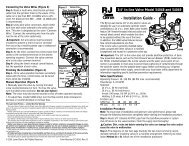
B. Connect Valve Wires to the Sprinkler Timer<br />
• Strip 1/4" (6 mm) of the plastic insulation off the end<br />
of each wire.<br />
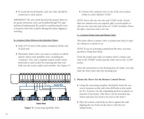
• Determine which valve you want to connect to which<br />
station. Insert each sprinkler wire, excluding the<br />
“common” wire, into a separate station socket (numbered<br />
above each socket) by inserting the bare wire<br />
fully into the socket under each number. (See Figure 5)<br />
• Connect the common wire to one of the two sockets<br />
(white in color) labeled “COM.”<br />
NOTE: Insert only one wire into each “COM” socket. If more<br />
than two common wires are required, splice several together so<br />
only one wire runs into each of the two “COM” terminals. Protect<br />
the splice connection with a wire nut.<br />
C. Connect Pump Start and Master Valve<br />
This timer allows a master valve or pump start relay to operate<br />
whenever a station is on.<br />
NOTE: If you are activating a pump from this timer, you must<br />
purchase a Pump Start Relay.<br />
From the pump start relay (or master valve); connect one<br />
wire to the “PUMP” socket and the other wire to the “COM”<br />
socket.<br />
Once all connections to the docking port are made, you may<br />
slide the timer back onto the docking port.<br />
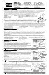
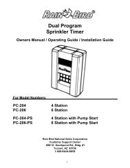
SENSOR COM PUMP 1 2 3 4 5 6 7 8 9 10 11 12 24 VAC<br />
5. Mount the Sleeve for the Remote Control Device<br />
Terminal Button<br />
Common Wire<br />
• Using the mounting template (included) mark the two<br />
screw locations on the wall, then drill holes at the marks<br />
for No. 8 screws. Use the expanding anchors in plaster or<br />
masonry if necessary. (The sleeve can be mounted any<br />
where and does not need to be next to the timer.)<br />
Station Valves<br />
Figure 5: Connecting Sprinkler Wire<br />
• Place the remote control device sleeve against the wall,<br />
aligning the two holes in the sleeve with the two<br />
drilled holes.<br />
14