NYCDEPCostAnalys isReport-0607 .pdf - New York-New Jersey ...
NYCDEPCostAnalys isReport-0607 .pdf - New York-New Jersey ...
NYCDEPCostAnalys isReport-0607 .pdf - New York-New Jersey ...

Create successful ePaper yourself
Turn your PDF publications into a flip-book with our unique Google optimized e-Paper software.
Executive Summary<br />
At the request of the <strong>New</strong> <strong>York</strong> City Department of Environmental Protection (NYCDEP) the<br />
Advanced Wastewater Treatment Programmatic Assistance Team (AWT Team) has developed<br />
conceptual designs, cost estimates and treatment projections for ten levels of treatment at four of<br />
the City’s Water Pollution Control Plants (WPCPs): Port Richmond, Red Hook, North River, and<br />
Owls Head. This work was prepared in response to the Nutrient Workgroup of the <strong>New</strong> <strong>York</strong>-<br />
<strong>New</strong> <strong>Jersey</strong> Harbor Estuary Plan (HEP), which has expressed an intent to promulgate a Total<br />
Maximum Daily Load (TMDL) for nitrogen and carbon by December 31, 2008 for sections of<br />
<strong>New</strong> <strong>York</strong> Harbor. Detailed water quality modeling is underway that will specify the limiting<br />
nutrient – carbon, nitrogen, or a combination of the two – and the key zones of the harbor in need<br />
of load reduction. The nutrient workgroup has stated that it will consider the associated costs of<br />
advanced treatment alternatives in combination with their projected water quality benefit.<br />
The year 2045 was selected as the design horizon for this project, and a set of projected flows<br />
and loads were developed and agreed upon for this effort. Conceptual design reports and<br />
drawing sets were prepared at each of the facilities selected for in-depth analysis. Projected<br />
annual average effluent concentrations were developed from BioWin process modeling and fullscale<br />
experience. Capital cost estimates were prepared from these conceptual design reports,<br />
drawing sets, and a set of contingencies and escalation factors were applied appropriate for the<br />
<strong>New</strong> <strong>York</strong> City marketplace.<br />
The Team’s conceptual capital cost curves are presented in this executive summary. These cost<br />
curves include conceptual costs developed on behalf of HEP. Where available, these conceptual<br />
cost curves were supplemented with known construction costs (escalated to 2007 dollars) for<br />
Advanced Basic BNR and Full Step BNR technologies currently under construction at Upper<br />
East River WPCPs. These conceptual capital cost estimates do not include the cost of land<br />
acquisition, which are unknown at this time. Land acquisition is likely to be a major cost driver<br />
for advanced technologies at space-constrained plants such as North River, Owls Head, and to a<br />
lesser extend Red Hook.<br />
This submittal intends to fulfill the HEP Nutrient Workgroup’s request for draft cost information.<br />
Objectives for the final submittal in November 2007 include providing operation and<br />
maintenance (O&M) cost curves as well as capital costs, and refining this report based on the<br />
feedback provided by NYCDEP and HEP.<br />
Background<br />
Low levels of dissolved oxygen (DO) have been observed in various locations throughout the<br />
<strong>New</strong> <strong>York</strong>-<strong>New</strong> <strong>Jersey</strong> Harbor Estuary in numerous water quality sampling studies. Water<br />
quality modeling shows that low levels of dissolved oxygen will continue to persist in future<br />
conditions. This water quality modeling work has shown that both nitrogen and carbon<br />
discharges have an impact on harborwide water quality issues. The degree to which these two<br />
constituents influence DO levels under varying conditions is an additional variable at play. HEP<br />
is developing management zones for locations throughout the Harbor, similar in nature to the<br />
Long Island Sound Study (LISS) management zones, of which, the Upper and Lower East River<br />
are a part. In the long term, these management zones may be used to establish Total Maximum<br />
___________________________________________________________________________________________________________<br />
EX-1
Daily Loads (TMDLs) for <strong>New</strong> <strong>York</strong> Harbor, which would impact Water Pollution Control<br />
Plants (WPCPs) in <strong>New</strong> <strong>York</strong> and <strong>New</strong> <strong>Jersey</strong> as well as nonpoint sources of discharge.<br />
HydroQual has been tasked with the System Wide Eutrophication Modeling (SWEM) to<br />
determine critical management zones that impact Harbor water quality, and within those key<br />
management zones, determining which nutrient is the critical resource. This focusing of HEP on<br />
key WPCPs and nutrients is anticipated to be completed in the next 6-8 months.<br />
Key unknowns at this time are:<br />
• HEP has not clarified which <strong>New</strong> <strong>York</strong> City WPCPs (if any) will be targeted for nutrient<br />
removal enhancements. If water quality modeling has progressed to the point where HEP<br />
could narrow NYCDEP’s efforts, this would allow the Team to focus its limited resources on<br />
the plants most likely targeted for upgrades.<br />
• What set of water quality standards will be used to assess compliance scenarios?<br />
• Does HEP intend to promulgate an annual average TMDL, such as the Total Nitrogen TMDL<br />
under the Long Island Sound Study? Or does HEP intend to promulgate a limit based on a<br />
different timeperiod, such as a maximum monthly average or an instantaneous maximum?<br />
Approach<br />
Upon project approval, the Team acquired the necessary documentation and materials for the<br />
development of the project. Information included design drawings, site plans, historical data,<br />
and information about future upgrades. The Team also visited plant sites in order to discuss<br />
process control and operation to gain a better understanding of potential plant limitations to<br />
achieve higher levels of treatment.<br />
The Team utilized the most recent projections for wastewater flows for WPCPs in the calculation<br />
of projected influent loadings to each plant for the year 2045, which is the design and modeling<br />
milestone for project work. These flow projections are based on historical wastewater data in<br />
conjunction with available population and employment projections for each WPCP service area.<br />
The Team evaluated potential industrial contributions in drainage areas that have a significant<br />
industrial component.<br />
A set of project-wide global assumptions was established for this effort. In addition to project<br />
flows and loads, an N+1 level of redundancy was chosen for process infrastructure (tanks,<br />
filtration units, etc) and an N+1+1 level of redundancy was chosen for process equipment<br />
(pumps, blowers, etc). From a hydraulic standpoint, all unit processes were designed for 1.5<br />
times the WPCP’s design dry weather flow (DDWF) capacity; the preservation of the secondary<br />
bypass channel is assumed within this work.<br />
The conceptual design reports for Port Richmond, Red Hook, North River, and Owls Head<br />
follow this executive summary.<br />
Selection of Technologies<br />
The following ten levels of treatment were chosen for this project. The first two levels of<br />
treatment are presented to provide context for a potential ‘knee-of-the-curve’ analysis, followed<br />
by eight levels of technology that remove nitrogen and/or carbon to varying degrees. The first<br />
___________________________________________________________________________________________________________<br />
EX-2
two options are defined for process modeling purposes, as <strong>New</strong> <strong>York</strong> City WPCPs currently<br />
exceed base secondary treatment standards. These levels do enter our costing analysis.<br />
• Base Case – The base case is developed using the design dry weather flow rate (DDWF) and<br />
the projected 2045 wastewater characteristics. A TN removal of 35 percent and an effluent<br />
CBOD of 25 mg/L and TSS of 30 mg/L are assumed. Removals of 85 percent for CBOD<br />
and TSS were applied when this condition proven to be stricter. These characteristics are<br />
consistent with SPDES permit requirements.<br />
• Existing Conditions – Based on the plant flow and effluent quality for Fiscal Years 2003 to<br />
2005, this level assumes the current plant performance observed will continue.<br />
• Existing Conditions with Solids Filtration – Equivalent to the previous level of technology<br />
plus filtration. The Filtration design level utilizes deep bed filters provided at the end of the<br />
secondary process train to reduce the particulate fraction of the secondary effluent discharged<br />
under the existing conditions. This technology preserves the existing secondary treatment<br />
infrastructure, but designs the additional unit process based on the plant-specific 2045 flows<br />
and loads. (carbon only)<br />
• Existing Conditions with Microfiltration/Ultrafiltration – The<br />
Microfiltration/Ultrafiltration design level further reduces the particulate fraction of the<br />
secondary effluent from the existing conditions through the implementation of membrane<br />
technology. This technology preserves the existing secondary treatment infrastructure, but<br />
designs the additional unit process based on the plant-specific 2045 flows and loads. (carbon<br />
only)<br />
• Advanced Basic BNR – Based on the original AWT design guidance, the Advanced Basic<br />
BNR design will provide enhancements to the current step feed operation for increased BNR<br />
performance at the facilities. This level of treatment is currently under construction at the<br />
Bowery Bay, Wards Island, and Tallman Island WPCPs to meet Long Island Sound Total<br />
Nitrogen goals. (nitrogen only)<br />
• Full Step BNR – This treatment level provides the Advanced Basic BNR level with<br />
additional flexibility, and incorporates supplemental carbon addition to enhance<br />
denitrification. This level of treatment is currently under construction at the Hunts Point<br />
WPCP to meet Long Island Sound Total Nitrogen goals. (nitrogen only)<br />
• Full Step BNR with Solids Filtration – Equivalent to the previous level of technology, the<br />
Filtration design level would utilize deep bed filters at the end of the process train to reduce<br />
the particulate fraction of the secondary effluent discharge. (carbon and nitrogen)<br />
• Full Step BNR with Microfiltration/Ultrafiltration – The Microfiltration/Ultrafiltration<br />
design level further reduces the particulate fraction of the secondary effluent through the<br />
implementation of membrane technology. (carbon and nitrogen)<br />
___________________________________________________________________________________________________________<br />
EX-3
• Full Step BNR with Denitrification Filters – Denitrification filters provided at the end of<br />
secondary process train will remove additional particulates and nutrients from the secondary<br />
effluent. (carbon and nitrogen)<br />
• Membrane Bioreactor Tanks – Provides the greatest improvement in effluent quality, but<br />
will require different technology than the standard step-feed BNR configurations with the<br />
installation of Membrane Bioreactors. (carbon and nitrogen)<br />
Effluent Projections<br />
Table EX-1 provides the estimated annual average effluent quality for each level of treatment<br />
for all 14 <strong>New</strong> <strong>York</strong> City WPCPs. Table EX-1 pulls from several analyses, including this<br />
conceptual design conducted at Port Richmond, Red Hook, North River, and Owls Head, BioWin<br />
analysis conducted at the Jamaica Bay WPCPs (26 th Ward, Coney Island, Jamaica, and<br />
Rockaway), and a BioWin analysis conducted at the Upper East River WPCPs (Bowery Bay,<br />
Hunts Point, Tallman Island, and Wards Island).<br />
Cost Estimation<br />
Conceptual cost estimates were developed for each of the eight new technologies at the four<br />
WPCPs included in this study. Table EX-2 highlights key costing assumptions and<br />
contingencies. Each of these assumptions is based on best available information culled from<br />
recent competitive bids on major NYCDEP capital construction projects. The detailed<br />
conceptual cost estimates provided in this report include major unit process improvements and<br />
the ancillary equipment needed to support them. Detailed plant-specific designs are beyond the<br />
scope of this conceptual study, and the project design contingency was selected to account for<br />
these costs. A higher design contingency was selected for the membrane bioreactor level of<br />
technology, as this technology has not yet been implemented at plants as big as the North River<br />
WPCP. This higher contingency reflects greater uncertainty as well as unanticipated scale-up<br />
issues for this limit of technology alternative.<br />
___________________________________________________________________________________________________________<br />
EX-4
WPCP<br />
26th<br />
Ward<br />
Bowery<br />
Bay<br />
Coney<br />
Island<br />
Hunts<br />
Point<br />
Jamaica<br />
<strong>New</strong>town<br />
Creek<br />
North<br />
River<br />
Oakwood<br />
Beach<br />
Nutrient<br />
Base<br />
Case*<br />
Flow (mgd) 85<br />
Carbon (mg/L)
WPCP<br />
Owls<br />
Head<br />
Port<br />
Richmond<br />
Red Hook<br />
Rockaway<br />
Tallman<br />
Island<br />
Nutrient<br />
Base<br />
Case*<br />
Flow (mgd) 120<br />
Carbon (mg/L)
Table EX-2: Key Cost Assumptions<br />
Annual Cost Escalation 8.5%<br />
Assumed Construction Start Date 2020<br />
Cost Basis<br />
June 2007 Dollars<br />
Land Acquisition Costs<br />
Not included<br />
4 Years for ABBNR<br />
Construction Duration<br />
5 Years for FSBNR<br />
8 Years for all other technologies<br />
Contractor Overhead and Profit 21%<br />
Design Contingency<br />
60% for MBR<br />
40% for all other technologies<br />
Bond and Insurance 6%<br />
Construction Allowances and Unit Price Items 6%<br />
Table EX-3 provides capital construction cost estimates for each technology at each WPCP in<br />
this study. These figures exclude the cost of land acquisition at space constrained facilities,<br />
which would be major cost drivers at the North River and Owls Head WPCPs. Detailed cost<br />
estimates follow the conceptual design reports in this deliverable.<br />
Table EX-3: Estimated Capital Construction Costs (Escalated to the Midpoint of<br />
Construction)<br />
North River Owls Head Red Hook Port Richmond<br />
Solids Filtration $587 $485 $307 $274<br />
Microfiltration/<br />
Ultrafiltration<br />
$813 $650 $379 $374<br />
Advanced Basic<br />
BNR<br />
$434 $257 $225 $216<br />
Full Step BNR $499 $319 $296 $270<br />
Full Step BNR with<br />
Solids Filtration<br />
$1,334 $931 $632 $501<br />
Full Step BNR with<br />
Denitrification<br />
$1,501 $1,051 $682 $578<br />
Full Step BNR with<br />
Microfiltration/ $1,568 $1,096 $704 $601<br />
Ultrafiltration<br />
Membrane<br />
Bioreactor<br />
$3,210 $2,345 $1,572 $1,398<br />
Technology Cost Curves<br />
Figures EX-1 through EX-8 provide cost curves for capital construction costs for each level of<br />
technology included in this study. Previous work conducted at several <strong>New</strong> <strong>York</strong> City WPCPs<br />
that yielded costs for various treatment and technology levels were included in some of the cost<br />
curves, including an analysis examining the impact of BNR upgrades at the four Upper East<br />
River WPCPs (Bowery Bay, Hunts Point, Tallman Island, and Wards Island).<br />
___________________________________________________________________________________________________________<br />
EX-7
Plant sizes are in millions of gallons per day and costs are in millions of 2007 dollars with the<br />
impact of escalation excluded. Actual construction costs for Advanced Basic BNR and Full Step<br />
BNR from the <strong>New</strong> <strong>York</strong> City Nitrogen program are also included.<br />
Figure EX-1: Solids Filtration<br />
$160<br />
$140<br />
y = 4.283x 0.6919<br />
R 2 = 0.9801<br />
North River<br />
$120<br />
Owl's Head<br />
Cost (Millions 2007 Dollars)<br />
$100<br />
$80<br />
$60<br />
Red Hook<br />
Port Richmond<br />
$40<br />
$20<br />
$0<br />
0 20 40 60 80 100 120 140 160 180<br />
Plant Size (MGD)<br />
The best fit cost curve is y= $4.283x 0.6919 ; this has an R 2 correlation of 0.9801. Note this<br />
equation estimates the capital construction cost (in millions of 2007 dollars) excluding the<br />
impact of escalation. Escalated cost is a more accurate representation of future project costs.<br />
This curve is statistically valid over a range of 60-170 mgd.<br />
___________________________________________________________________________________________________________<br />
EX-8
Figure EX-2: Microfiltration/Ultrafiltration<br />
$250<br />
Capital Construction Cost (Millions 2007 Dollars)<br />
$200<br />
$150<br />
$100<br />
$50<br />
Red Hook<br />
Port Richmond<br />
Owl's Head<br />
y = 4.3975x 0.7491<br />
R 2 = 0.9981<br />
North River<br />
$0<br />
0 20 40 60 80 100 120 140 160 180<br />
Plant Size (MGD)<br />
The best fit cost curve is y= $4.3975x 0.7491 ; this has an R 2 correlation of 0.9981. Note this<br />
equation estimates the capital construction cost (in millions of 2007 dollars) excluding the<br />
impact of escalation. Escalated cost is a more accurate representation of future project costs.<br />
This curve is statistically valid over a range of 60-170 mgd.<br />
___________________________________________________________________________________________________________<br />
EX-9
Figure EX-3: Advanced Basic BNR<br />
$250<br />
Capital Construction Cost (Millions 2007 dollars)<br />
$200<br />
$150<br />
$100<br />
$50<br />
Red Hook<br />
Port Richmond<br />
Tallman Island<br />
Owl's Head<br />
Bowery Bay<br />
North River<br />
y = 4.9287x 0.6463<br />
R 2 = 0.6947<br />
Wards Island<br />
$0<br />
0 50 100 150 200 250 300<br />
Plant Size (MGD)<br />
The best fit cost curve is y= $4.9287x 0.6463 ; this has an R 2 correlation of 0.6947. Note this<br />
equation estimates the capital construction cost (in millions of 2007 dollars) excluding the<br />
impact of escalation. Escalated cost is a more accurate representation of future project costs.<br />
This curve is statistically valid over a range of 60-275 mgd.<br />
___________________________________________________________________________________________________________<br />
EX-10
Figure EX-4: Full Step BNR<br />
$350<br />
Capital Construction Cost (Millions 2007 Dollars)<br />
$300<br />
$250<br />
$200<br />
$150<br />
$100<br />
$50<br />
Red Hook<br />
Port Richmond<br />
Owl's Head<br />
y = 1.9455x 0.8731<br />
R 2 = 0.7014<br />
North River<br />
Hunts Point<br />
$0<br />
0 50 100 150 200 250<br />
Plant Size (MGD)<br />
The best fit cost curve is y= $1.9455x 0.8731 ; this has an R 2 correlation of 0.7014. Note this<br />
equation estimates the capital construction cost (in millions of 2007 dollars) excluding the<br />
impact of escalation. Escalated cost is a more accurate representation of future project costs.<br />
This curve is statistically valid over a range of 60-200 mgd.<br />
___________________________________________________________________________________________________________<br />
EX-11
Figure EX-5: Full Step BNR with Solids Filtration<br />
$400<br />
Capital Construction Cost (Millions 2007 Dollars)<br />
$350<br />
$300<br />
$250<br />
$200<br />
$150<br />
$100<br />
$50<br />
Red Hook<br />
Port Richmond<br />
Owl's Head<br />
y = 5.1246x 0.8068<br />
R 2 = 0.9454<br />
North River<br />
$0<br />
0 20 40 60 80 100 120 140 160 180<br />
Plant Size (MGD)<br />
The best fit cost curve is y= $5.1246x 0.8068 ; this has an R 2 correlation of 0.9454. Note this<br />
equation estimates the capital construction cost (in millions of 2007 dollars) excluding the<br />
impact of escalation. Escalated cost is a more accurate representation of future project costs.<br />
This curve is statistically valid over a range of 60-170 mgd.<br />
___________________________________________________________________________________________________________<br />
EX-12
Figure EX-6: Full Step BNR with Denitrification Filtration<br />
$400<br />
Capital Construction Cost (Millions 2007 Dollars)<br />
$350<br />
$300<br />
$250<br />
$200<br />
$150<br />
$100<br />
$50<br />
Red Hook<br />
Port Richmond<br />
Owl's Head<br />
y = 5.4967x 0.8166<br />
R 2 = 0.9704<br />
North River<br />
$0<br />
0 20 40 60 80 100 120 140 160 180<br />
Plant Size (MGD)<br />
The best fit cost curve is y= $5.9467x 0.8166 ; this has an R 2 correlation of 0.9704. Note this<br />
equation estimates the capital construction cost (in millions of 2007 dollars) excluding the<br />
impact of escalation. Escalated cost is a more accurate representation of future project costs.<br />
This curve is statistically valid over a range of 60-170 mgd.<br />
___________________________________________________________________________________________________________<br />
EX-13
Figure EX-7: Full Step BNR with Microfiltration/Ultrafiltration<br />
$450<br />
Capital Construction Cost (Millions 2007 Dollars)<br />
$400<br />
$350<br />
$300<br />
$250<br />
$200<br />
$150<br />
$100<br />
$50<br />
Red Hook<br />
Port Richmond<br />
y = 5.5231x 0.8243<br />
Owl's Head<br />
R 2 = 0.9731<br />
North River<br />
$0<br />
0 20 40 60 80 100 120 140 160 180<br />
Plant Size (MGD)<br />
The best fit cost curve is y= $5.5231x 0.8243 ; this has an R 2 correlation of 0.9731. Note this<br />
equation estimates the capital construction cost (in millions of 2007 dollars) excluding the<br />
impact of escalation. Escalated cost is a more accurate representation of future project costs.<br />
This curve is statistically valid over a range of 60-170 mgd.<br />
___________________________________________________________________________________________________________<br />
EX-14
Figure EX-8: Membrane Bioreactor<br />
$900<br />
North River<br />
$800<br />
y = 19.027x 0.7236<br />
Capital Construction Cost (Millions 2007 Dollars)<br />
$700<br />
$600<br />
$500<br />
$400<br />
$300<br />
$200<br />
Red Hook<br />
Port Richmond<br />
R 2 = 0.9794<br />
Owl's Head<br />
$100<br />
$0<br />
0 20 40 60 80 100 120 140 160 180<br />
Plant Size (MGD)<br />
The best fit cost curve is y= $19.027x 0.7236 ; this has an R 2 correlation of 0.9794. Note this<br />
equation estimates the capital construction cost (in millions of 2007 dollars) excluding the<br />
impact of escalation. Escalated cost is a more accurate representation of future project costs.<br />
This curve is statistically valid over a range of 60-170 mgd.<br />
Next Steps<br />
The Team will augment this deliverable for the HEP Nutrient Workgroup’s final deliverable<br />
deadline of November 2007. Goals for the Team’s work include:<br />
• Developing O&M cost estimates in addition to capital cost estimates<br />
• Verifying the adequacy of the various conceptual capital construction cost curves,<br />
particularly for carbon technologies where only four <strong>New</strong> <strong>York</strong> City data points are<br />
available.<br />
• Expanding the predictive range of each cost curve.<br />
• Conducting an independent review of cost estimates.<br />
• Incorporating NYCDEP and HEP feedback, and revising and resubmitting this work Fall<br />
2007.<br />
___________________________________________________________________________________________________________<br />
EX-15
1 INTRODUCTION<br />
At times the water quality of the <strong>New</strong> <strong>York</strong>-<strong>New</strong> <strong>Jersey</strong> Harbor estuary falls below water quality<br />
standards. Since the estuary was accepted into the National Estuary Program in 1988, water<br />
quality issues have been a major focus for improvement. The Harbor Estuary Program (HEP), a<br />
joint effort between <strong>New</strong> <strong>York</strong>, <strong>New</strong> <strong>Jersey</strong> and the United States Environmental Protection<br />
Agency (USEPA), evaluated these water quality concerns and prepared a Comprehensive<br />
Conservation and Management Plan (CCMP). Within the CCMP, significant problems have<br />
been identified and include:<br />
• Habitat loss and degradation (such as loss of wetlands)<br />
• Toxic contamination (including metals and pesticides)<br />
• Pathogen contamination<br />
• Floatable debris (originating from improper trash disposal and decay of shoreline structures)<br />
• Nutrient and organic enrichment (including increased carbon loadings and increased nitrogen<br />
loadings resulting in reduced dissolved oxygen levels)<br />
The goals of the <strong>New</strong> <strong>York</strong>/<strong>New</strong> <strong>Jersey</strong> Harbor Estuary Program are to bring the Harbor waters<br />
into compliance with the Clean Water Act. The various areas focused on in this conceptual<br />
design include:<br />
• Meeting the Fishable/Swimable goal of the Clean Water Act<br />
• Meeting the Fishable/Swimable goal for Toxics<br />
• Attaining a Fishable/Swimable status in terms of nutrients and Oxygen levels<br />
• Making Harbor waters free from floatable debris<br />
• Preserving, managing, and enhancing the Estuary’s vital habitat, ecological function, and<br />
biodiversity so that the Harbor is a system of diverse natural communities<br />
• Ensuring that all residents in the core area of the Harbor have a public waterfront access site<br />
within thirty minutes of their home for boating, fishing, swimming and/or waterfront leisure<br />
(e.g. walking, bird watching, and picnicking), without harming important habitat areas<br />
• Reducing sediment hot spots, and point and non-point sources of contaminants entering the<br />
Harbor, such that levels of toxics in newly deposited sediments do not inhibit a healthy<br />
thriving ecosystem and can be dredged and beneficially reused<br />
HEP is developing a plan to improve water quality and is evaluating the impact of wastewater<br />
treatment improvements on receiving waters. The cost for different levels of treatment will be<br />
considered during the development of the plan. The <strong>New</strong> <strong>York</strong> City Department of<br />
Environmental Protection (NYCDEP) is independently developing conceptual designs and cost<br />
estimates for nitrogen and carbon removal technologies at several Water Pollution Control Plants<br />
(WPCPs) that discharge to the Harbor. The conceptual designs will cover several levels of<br />
technology, including Existing Conditions with Solids Filtration, Existing Conditions with<br />
Microfiltration/Ultrafiltration, Advanced Basic BNR Treatment, Full Step BNR Treatment, Full<br />
Step BNR Treatment with Solids Filtration, Full Step BNR Treatment with<br />
Microfiltration/Ultrafiltration, Full Step BNR Treatment with Denitrification Filters, and<br />
Membrane Bioreactors. This report describes the existing conditions at the Port Richmond<br />
WPCP and the potential upgrades that can be implemented for each level of technology.
This report includes four conceptual design reports prepared by the NYCDEP as requested by the<br />
HEP nutrient workgroup. To date, the NYCDEP has prepared conceptual design reports for the<br />
Red Hook, Port Richmond, North River, and Owls Head WPCPs in support of the HEP analysis.<br />
1.1 Treatment Technologies<br />
As part of the Harbor Estuary Program, the Advanced Wastewater Treatment Program<br />
Assistance (AWTPA) Team will develop conceptual designs for nitrogen and carbon removal<br />
technologies at the four WPCPs. Ten levels of treatment were identified as well as<br />
corresponding sets of secondary effluent characteristics that should be achieved at each level.<br />
The ten levels identified are described in detail below and are listed here:<br />
• Base Case<br />
• Existing Conditions<br />
• Existing Conditions with Solids Filtration<br />
• Existing Conditions with Microfiltration/Ultrafiltration<br />
• Advanced Basic BNR<br />
• Full Step BNR<br />
• Full Step BNR with Solids Filtration<br />
• Full Step BNR with Microfiltration/Ultrafiltration<br />
• Full Step BNR with Denitrification Filters<br />
• Membrane Bioreactor Tanks<br />
It should be emphasized that possible changes in wastewater quality and quantity between now<br />
and 2045 could heavily influence technology selection and may result in additional technologies<br />
being considered in the future. In addition, this analysis is based on evaluating current “state-ofthe-art”<br />
treatment technologies. The evolution of current technologies in addition to any new<br />
treatment processes may provide additional options to be assessed in the future.<br />
1.1.1 Base Case<br />
The Base Case scenario is based on the treatment level permitted for the WPCP. The principal<br />
design considerations include:<br />
• 25 mg/L CBOD 5 and 30 mg/L TSS or 85% removal, whichever is stricter<br />
• Assume 35% removal of TN, based on the projected nitrogen loading for 2045. The same<br />
TN removal efficiency is assumed for all WPCPs considered in this project<br />
• Design dry weather flow rate<br />
• Assumed treatment levels are shown for each plant in Table EX-1 in the Executive Summary<br />
The base case scenario is defined as the treatment level that meets the current permit levels for<br />
wastewater discharge. The treatment process evaluated for the base case is the existing<br />
condition.
The treatment levels to be examined for the base case are the levels upon which each WPCP is<br />
permitted to operate. The permit levels described in the State Pollutant Discharge Elimination<br />
System (SPDES) are summarized in Table 1-1.<br />
Flow<br />
Table 1-1: Permit Limits, Levels and Monitoring Requirements for the HEP WPCPs<br />
Permit Sample<br />
Parameter Unit Type<br />
Remarks<br />
level frequency<br />
mgd<br />
12 months avg<br />
CBOD 5 mg/L<br />
Monthly avg<br />
7-day avg<br />
TSS<br />
Nitrogen<br />
Total<br />
Ammonia<br />
TKN<br />
Nitrite<br />
Nitrate<br />
Phosphorus<br />
Total<br />
Soluble (ortho)<br />
mg/L<br />
mg-N/L<br />
mg-P/L<br />
1.1.2 Existing Conditions<br />
Monthly avg<br />
7-day avg<br />
1-day maximum<br />
N/A<br />
N/A<br />
60 – PR<br />
60 – RH<br />
170 – NR<br />
120 – OH<br />
25<br />
40<br />
30<br />
45<br />
50<br />
To be<br />
monitored<br />
To be<br />
monitored<br />
Continuous<br />
1/day<br />
1/day<br />
1/day<br />
1/day<br />
1/day<br />
1/week<br />
2/month<br />
At least 85%<br />
removal<br />
At least 85%<br />
removal<br />
The Existing Conditions scenario maintains the treatment levels currently achieved at each<br />
WPCP. The design considerations include:<br />
<br />
<br />
<br />
Existing plant effluent quality for CBOD and TSS (using average of FY2003-05, see<br />
Table EX-1 and Table 1-2 below)<br />
Existing plant removal percentage for TN<br />
Existing plant flow<br />
Existing wastewater flow, influent concentrations, and effluent concentrations were calculated by<br />
taking averages of the operational data during fiscal years of 2003 through 2005. A summary of<br />
the existing plant influent and effluent characteristics from 2003 to 2005 is presented in Table 1-<br />
2.
Table 1-2: 2003-2005 Influent and Effluent Water Quality<br />
Plant<br />
Flow<br />
Waste<br />
CBOD CBOD TSS TSS TN TN<br />
rate<br />
Stream<br />
mgd mg/L lb/d mg/L lb/d mg/L lb/d<br />
26th Ward<br />
Influent 60 136 66,600 133 66,300 22 10,400<br />
Effluent - 7.9 3,900 14.1 7,000 14.6 7,300<br />
Bowery Bay<br />
Influent 116 138 131,500 122 117,100 30 28,800<br />
Effluent - 9.9 9,600 11.3 10,900 19.3 18,700<br />
Coney Island<br />
Influent 92 112 84,700 157 119,500 28 20,900<br />
Effluent - 8.0 6,100 13.9 10,600 17.1 13,100<br />
Hunts Point<br />
Influent 120 95 92,900 104 102,900 22 21,100<br />
Effluent - 10.2 10,200 12.3 12,300 20.1 20,100<br />
Jamaica<br />
Influent 82 147 98,700 142 96,200 30 19,500<br />
Effluent - 10.0 6,900 14.1 9,700 21.3 14,600<br />
<strong>New</strong>town Influent 231 136 259,500 160 309,100 24 45,900<br />
Creek Effluent - 37.8 72,800 30.0 57,800 18.2 35,100<br />
North River<br />
Influent 130 167 180,400 200 215,800 29 31,400<br />
Effluent - 11.4 12,300 15 16,200 18.4 19,900<br />
Oakwood Influent 31 120 30,400 183 46,800 30 7,500<br />
Beach Effluent - 6.6 1,700 13.0 3,400 20.0 5,200<br />
Owls Head<br />
Influent 102 167 141,600 185 157,300 30 25,700<br />
Effluent - 11.6 9,900 17.3 14,700 19.1 16,200<br />
Port Influent 36 175 49,900 182 53,700 26 7,300<br />
Richmond Effluent - 7.1 2,100 11.4 3,400 13.4 4,000<br />
Red Hook<br />
Influent 31 147 36,800 180 46,200 30 7,500<br />
Effluent - 6.8 1,800 7.8 2,000 16.1 4,200<br />
Rockaway<br />
Influent 20 72 12,000 103 17,100 19 3,100<br />
Effluent - 4.7 800 8.4 1,400 12.8 2,100<br />
Tallman Influent 58 117 55,800 126 60,300 27 12,700<br />
Island Effluent - 10.7 5,200 5.4 2,600 18.1 8,800<br />
Wards Island<br />
Influent 203 109 184,100 109 183,800 19 32,600<br />
Effluent - 5.6 9,500 9.3 15,700 16.8 28,400<br />
The Existing Conditions scenario is defined as the treatment level currently in place at each of<br />
the WPCPs. The treatment process and the treatment levels evaluated for the Existing<br />
Conditions scenario are the existing conditions.<br />
1.1.3 Existing Conditions with Solids Filtration<br />
The Existing Conditions with Solids Filtration (EC-SF) process will maintain all the existing<br />
infrastructure and processes currently in place at each WPCP, in addition to a solids filtration
process installed downstream of the secondary treatment process to enhance the removal of<br />
particulates in the wastewater, including solids, particulate BOD, and particulate TKN.<br />
Secondary effluent is applied to a filter bed and the filter media within the bed physically remove<br />
and store particulates from the waste stream. Sand or anthracite is typically used for the media.<br />
Secondary effluent is evenly applied to the filters at a constant flowrate per surface area, until<br />
accumulated solids within the filter reduce the filtration rate (or rate of application). To restore<br />
the filter, a backwash operation is performed with air and/or water to purge the media.<br />
A schematic of the process is shown in Figure 1-1.<br />
Figure 1-1: EC-SF Process Configuration<br />
1.1.4 Existing Conditions with Microfiltration/Ultrafiltration<br />
The Existing Conditions with Microfiltration/Ultrafiltration (EC-MF) process will maintain all<br />
the existing infrastructure and processes currently in place at each WPCP, in addition to a<br />
membrane filter process installed downstream of the secondary treatment process to further<br />
enhance the removal of particulates in the wastewater. Filtered secondary effluent would be
extracted through the membranes as a permeate. Compared to filtration, the removals are greater<br />
due to typical pore sizes between 0.1 to 0.2 m.<br />
The mechanism of membrane filtration is to use hydrostatic pressure to force liquid against a<br />
semipermeable membrane. Only the liquid and particles smaller than the membrane's pore size<br />
can pass through. Pore size refers to the diameter of the spherical particle that the filter would<br />
retain. A filter is rated with two pore sizes corresponding to two tiers of retention efficiency:<br />
• Absolute pore size - the particle size retained with 100% efficiency<br />
• Nominal pore size - the particle size retained with a selected majority efficiency<br />
Membrane filters are designated by pore sizes as shown in Table 1-3.<br />
Filtration<br />
Type<br />
Membrane<br />
filtration<br />
Ultrafiltration<br />
Nanofiltration<br />
Pore<br />
Size<br />
(µm)<br />
0.1-10<br />
0.01<br />
0.001<br />
Reverse<br />
Osmosis 0.0001<br />
Table 1-3: Membrane Filter Designations<br />
Pressure<br />
low-pressure<br />
cross-flow<br />
up to 145 psi<br />
(10 bar)<br />
mid-range<br />
pressure<br />
30–250 psi<br />
(2–17 bar)<br />
high-pressure<br />
Removal<br />
Turbidity. Colloidal and suspended particles including<br />
fats<br />
Microorganisms/pathogens, viruses, high molecularweight<br />
substances, organic and inorganic polymeric<br />
molecules including proteins, silicates<br />
Color. Demineralization, desalination (divalent salts),<br />
softening (polyvalent cation removal), sugars, pesticides,<br />
herbicides<br />
All suspended and dissolved solids. Low-molecularweight<br />
substances such as monovalent salts<br />
Membrane filtration is not commonly used on the scale of full tertiary treatment. It achieves<br />
removals far in excess of current regulation, and does so at significantly greater cost than<br />
conventional filtration.<br />
A schematic of the process is shown in Figure 1-2.
1.1.5 Advanced Basic BNR<br />
Figure 1-2: EC-MF Process Configuration<br />
Advanced Basic Biological Nitrogen Removal (ABBNR) is a process that maximizes the use of<br />
existing facilities to removal nitrogen from the process stream. The process was developed by<br />
the NYCDEP in the 1990s at the Tallman Island WPCP and has been further developed through<br />
continued research and testing. It is currently being implemented at five of the 14 NYCDEP<br />
WPCPs.<br />
The process involves modification of the existing step aeration process to include the cycling of<br />
oxic and anoxic zones that are necessary to remove nitrogen. ABBNR calls for maximized use<br />
of existing infrastructure and footprints (i.e. not changing location of gates, replacing air headers,<br />
or modify other major equipment, if possible). The process will require baffle walls to separate<br />
the oxic and anoxic portions of the tank and pre-anoxic zones to minimize the DO carryover<br />
from oxic to anoxic switch zones. Mixers will be required in the anoxic zones to keep solids in<br />
suspension and prevent the formation of stagnant zones. The anoxic zones will be fitted with<br />
membrane diffusers and isolated air droplegs to allow the zone to operate in an aerobic mode to<br />
meet the winter nitrification requirements. The blower and aeration system will be expanded to<br />
meet the needs of nitrogen removal. The RAS system will also be expanded to maximize the
capacity within the constraints of the existing facility. Automated flow control to Pass D will be<br />
provided to further enhance clarifier operation along with the capability to add polymer. The<br />
production of biological foam or froth is associated with the longer SRTs needed for<br />
nitrification. ABBNR includes three methods to control froth: RAS chlorination, froth hoods,<br />
and froth wasting. A moderate level of instrumentation will also be provided. A schematic of<br />
the process is shown in Figure 1-3.<br />
Figure 1-3: ABBNR Process Configuration<br />
In addition, this technology typically includes the capability to direct sludge dewatering centrate<br />
to a dedicated aeration tank for separate nitrification. A portion of mainstream RAS would be<br />
added to seed the process and alkalinity would be provided to satisfy the centrate nitrification<br />
requirement. Nitrified centrate would be returned to the head of the A Pass of the remaining<br />
tanks to be further treated. At Port Richmond, sludge is shipped to another facility for<br />
dewatering and therefore this capability will not be provided.<br />
1.1.6 Full Step BNR
The Full Step BNR (FSBNR) process is similar to the ABBNR, but provides additional control<br />
and flexibility. All of the components of ABBNR will be provided, in addition to the following:<br />
• Flow distribution and control will be provided on all 4 passes of the aeration tanks.<br />
• Alkalinity and Methanol facilities will be provided and sized to meet the load to the aeration<br />
tanks.<br />
• The RAS capacity will be expanded to 100% of the DDWF.<br />
• The process blowers and aeration system will be upgraded to meet the needs of the nitrogen<br />
removal process.<br />
A schematic of the process is shown in Figure 1-4.<br />
1.1.7 Full Step BNR with Solids Filtration<br />
Figure 1-4: FSBNR Process Configuration<br />
The FSBNR with Solids Filtration (FSBNR-SF) process will provide all of the components of<br />
FSBNR, in addition to a solids filtration process installed downstream of the secondary treatment<br />
process to enhance the removal of particulates in the wastewater, including solids, particulate<br />
BOD, and particulate TKN. Secondary effluent is applied to a filter bed and the filter media
within the bed physically remove and store particulates from the waste stream. Sand or<br />
anthracite is typically used for the media.<br />
Secondary effluent is evenly applied to the filters at a constant flowrate per surface area, until<br />
accumulated solids within the filter reduce the filtration rate (or rate of application). To restore<br />
the filter, a backwash operation is performed with air and/or water to purge the media.<br />
A schematic of the process is shown in Figure 1-5.<br />
Figure 1-5: FSBNR-SF Process Configuration<br />
1.1.8 Full Step BNR with Microfiltration/Ultrafiltration<br />
The FSBNR with Microfiltration/Ultrafiltration (FSBNR-MF) process will provide all of the<br />
components of FSBNR, in addition to a membrane filter process installed downstream of the<br />
secondary treatment process to further enhance the removal of particulates in the wastewater.<br />
Filtered secondary effluent would be extracted through the membranes as a permeate. Compared<br />
to filtration, the removals are greater due to typical pore sizes between 0.1 to 0.2 m.<br />
A schematic of the process is shown in Figure 1-6.
Figure 1-6: FSBNR-MF Process Configuration<br />
1.1.9 Full Step BNR with Denitrification Filters<br />
The FSBNR with denitrification filters (FSBNR-DF) process will provide all of the components<br />
of FSBNR, in addition to a denitrification filter process installed downstream of the secondary<br />
clarifiers and upstream of the disinfection system to both enhance the removal of particulates in<br />
the wastewater and remove Nitrogen through denitrification.<br />
This process will include all of the equipment listed for FSBNR plus the installation of<br />
denitrification filters and all supporting equipment. Supplemental carbon, such as methanol, will<br />
be added downstream of the FSBNR process rather than directly to the activated sludge process<br />
tanks. Denitrification filters are similar to conventional filters, however in addition to filtering<br />
out particulates, the media are used to grow fixed film denitrifying bacteria. These bacteria<br />
utilize methanol to convert nitrites and nitrates to free nitrogen gas and allows the overall process<br />
to achieve very low nitrogen levels.<br />
A schematic of the process is shown in Figure 1-7.
1.1.10 Membrane Bioreactors<br />
Figure 1-7: FSBNR-DF Process Configuration<br />
Membrane Bioreactors (MBR) are a combination of activated sludge reactors and membrane<br />
filtration facilities. Membrane facilities replace the clarification process by a physical barrier<br />
that separates solids from the liquid phase within the wastewater. Because the MBRs replace the<br />
clarifiers and provide a physical barrier, the aeration tanks can be operated at higher mixed liquor<br />
concentrations (approximately 8,500 mg/L) than conventional activated sludge systems. This<br />
allows for reduced tank sizes when compared to other activated sludge processes. The<br />
membranes used for this process are similar to the membrane filtration process, but they are<br />
operated at much lower flux rates (flow per unit) to handle the significantly higher solids loading<br />
rates.<br />
The process involves modification of the existing step aeration process to allow the entire flow<br />
stream to the head of the first pass. Zones will be created to allow the cycling of oxic and anoxic<br />
zones that are necessary to remove nitrogen. The process will require baffle walls to separate the<br />
oxic and anoxic portions of the tank. Mixers will be required in the anoxic zones to keep solids<br />
in suspension and prevent the formation of stagnant zones. The process will include the<br />
installation of fine screening, recirculation pumping, RAS pumping, and the construction of new
Membrane Bioreactors. The blower and aeration system will be expanded to meet the needs of<br />
nitrogen removal. Alkalinity feed systems will be provided to enhance nitrogen removal. The<br />
production of biological foam or froth is associated with the longer SRTs needed for<br />
nitrification. This technology includes three methods to control froth: RAS chlorination, froth<br />
hoods, and froth wasting. <strong>New</strong> instrumentation and controls will be provided.<br />
The process configuration consists of a series of four activated sludge process zones that cycle<br />
between nitrification and denitrification. The first and third zones are anoxic (un-aerated) and<br />
the second and fourth zones are aerobic (aerated). The MBR tanks are aerated to provide oxygen<br />
for the biomass and to provide scouring of the membrane surfaces. Return pumps remove excess<br />
solids from the MBR tanks and return them to the process tanks. Internal recycle pumping is<br />
provided between the third and first passes to maximize the nitrate concentration in the anoxic<br />
zones for denitrification. The effluent will be pumped to the disinfection tank and discharged. A<br />
schematic of the process is shown in Figure 1-8.<br />
Figure 1-8: Membrane Bioreactor Process Configuration<br />
A summary of each technology and the projected effluent concentrations is shown below in<br />
Table 1-4.
Table 1-4: Carbon and Nitrogen Removal Technologies Summary<br />
Level of Treatment<br />
Characteristics<br />
Base Case<br />
Effluent Characteristics:<br />
• Current permitted effluent quality, according to<br />
SPDES permit<br />
CBOD ≤ 25mg/L<br />
TSS ≤ 30mg/L<br />
• TSS = 30mg/L, CBOD = 25mg/L or 85% removal<br />
from influent conditions, whichever is stricter<br />
TN = 18-21mg/L<br />
• TN removal of 35%<br />
Existing Conditions<br />
Effluent Characteristics:<br />
CBOD = 8-15mg/L<br />
TSS = 8-18mg/L<br />
TN = 13-19mg/L<br />
Existing Conditions with Solids Filtration<br />
Effluent Characteristics:<br />
CBOD = 3-5mg/L<br />
TSS = 4-5mg/L<br />
TN = 13-19mg/L<br />
Existing Conditions with<br />
Microfiltration/Ultrafiltration<br />
Effluent Characteristics:<br />
CBOD = 1-2mg/L<br />
TSS = ~1mg/L<br />
TN = 13-19mg/L<br />
Advanced Basic BNR<br />
Effluent Characteristics:<br />
CBOD = 10-15mg/L<br />
TSS = 12-15mg/L<br />
TN = 10-12mg/L<br />
Full-Step BNR<br />
Effluent Characteristics:<br />
CBOD = 10-15mg/L<br />
TSS = 12-15mg/L<br />
TN = 6-10mg/L<br />
• Plant flow and effluent quality for Fiscal Years 2003 to<br />
2005<br />
• Assumes current performance observed will continue<br />
Same characteristics from Existing Conditions option, but<br />
with the following additions:<br />
• 1,500 mg/L AEMLSS<br />
• Deep-bed sand filters added after secondary treatment<br />
to provide additional solids and carbon removal<br />
• Water backwash and air scour system for filter<br />
cleaning<br />
Same characteristics from Existing Conditions option, but<br />
with the following additions:<br />
• 1,500 mg/L AEMLSS<br />
• Zenon Microfilters/Ultrafilters added after secondary<br />
treatment to provide additional solids and carbon<br />
removal<br />
• Air scour system for filter cleaning<br />
• 2 mm screens upstream of Microfilters/Ultrafilters<br />
Biological Nitrogen Removal Enhancements to Secondary<br />
treatment to include:<br />
• 2,000 mg/L AEMLSS<br />
• 0-33-33-33 flow split<br />
• Baffles to create switch zones<br />
• Anoxic and Pre-anoxic zones with mixers<br />
• Froth control hoods<br />
• Alkalinity addition<br />
• Return sludge capability at 50%<br />
Biological Nitrogen Removal Enhancements to Secondary<br />
treatment to include:<br />
• 2,500 mg/L AEMLSS<br />
• 10-40-30-20 flow split<br />
• Baffles to create switch zones<br />
• Anoxic and Pre-anoxic zones with mixers<br />
• Froth control hoods<br />
• Alkalinity addition<br />
• Return sludge capability at 100%<br />
• Methanol Addition
Level of Treatment<br />
Full-Step BNR with Solids Filtration<br />
Effluent Characteristics:<br />
CBOD = 3-5mg/L<br />
TSS = 4-5mg/L<br />
TN = 6-10mg/L<br />
Full-Step BNR with<br />
Microfiltration/Ultrafiltration<br />
Effluent Characteristics:<br />
CBOD = 1-2mg/L<br />
TSS = ~1mg/L<br />
TN = 6-10mg/L<br />
Full-Step BNR with Denitrification<br />
Filters<br />
Effluent Characteristics:<br />
CBOD = 3-5mg/L<br />
TSS = 4-5mg/L<br />
TN = 4-5mg/L<br />
Membrane Bioreactors<br />
Effluent Characteristics:<br />
CBOD = 1-2mg/L<br />
TSS = ~1mg/L<br />
TN = 3-4mg/L<br />
Characteristics<br />
Same characteristics from Full-Step BNR option, but with<br />
the following additions:<br />
• Deep-bed sand filters added after secondary treatment<br />
to provide additional solids and carbon removal<br />
• Water backwash and air scour system for filter<br />
cleaning<br />
Same characteristics from Full-Step BNR option, but with<br />
the following additions:<br />
• Zenon Microfilters/Ultrafilters added after secondary<br />
treatment to provide additional solids and carbon<br />
removal<br />
• Air scour system for filter cleaning<br />
• 2 mm screens upstream of Microfilters/Ultrafilters<br />
Same characteristics from Full-Step BNR option, but with<br />
the following additions:<br />
• Denitrification filters added after secondary treatment<br />
to provide additional solids, carbon, and nitrogen<br />
removal<br />
• Water backwash and air scour system for filter<br />
cleaning<br />
Zenon Membrane Bioreactor inclusion in Secondary<br />
treatment to include:<br />
• 8,500 mg/L AEMLSS (10,000 mg/L at OH)<br />
• Internal recycle from Pass C to Pass A<br />
• Anoxic zones<br />
• Alkalinity addition<br />
• Return sludge capability at 300%<br />
• Methanol Addition<br />
• Air scour system for filter cleaning<br />
• 6 mm and 2 mm screens upstream of MBRs<br />
1.2 Design Standards<br />
Basic design standards employed for the conceptual design are consistent for the four WPCPs<br />
considered in the HEP as summarized below:<br />
• Design standard is 1.5 times design dry weather flow for secondary treatment components<br />
sized on the basis of flow. Secondary bypass channel to be preserved<br />
• Design standard is 2.0 times dry weather flow for components before/after secondary bypass<br />
• Design standard is projected 2045 load for components sized on the basis of load<br />
• Degree of redundancy is N+1 for process infrastructure, N+1+1 for process equipment<br />
1.3 Influent Flows and Loads<br />
The flows and loads used for the basis of design for this evaluation are based on the NYCDEP<br />
Interim Water Demand and Wastewater Flow Projections developed by the Bureau of<br />
Environmental Planning and Assessment (BEPA) in July 2006, with the exception of the North<br />
River WPCP, which is explained in detail in Section 1.3.3. The projections utilized the
population projections prepared by the Department of City Planning, which in turn used the 2000<br />
Census. A summary table for the 2045 projected flows and loads at each WPCP in <strong>New</strong> <strong>York</strong><br />
City is presented in Table 1-5 below.<br />
Table 1-5: 2045 Influent Flow and Load Assumptions<br />
Plant Flow Inf BOD Inf TSS Inf TN<br />
mgd lb/d lb/d lb/d<br />
26th Ward 57 88,762 95,466 13,525<br />
Bowery Bay 131 147,284 133,903 32,526<br />
Coney Island 96 116,792 130,600 23,578<br />
Hunts Point 124 112,302 124,608 25,591<br />
Jamaica 89 122,050 109,987 23,844<br />
<strong>New</strong>town Creek 240 359,882 466,617 69,476<br />
North River 137 198,141 188,400 36,637<br />
Oakwood Beach 37 58,380 59,504 8,431<br />
Owls Head 105 161,275 149,979 27,119<br />
Port Richmond 38 78,322 71,578 9,145<br />
Red Hook 33 46,696 54,741 8,734<br />
Rockaway 24 18,006 19,401 4,279<br />
Tallman Island 62 68,909 65,273 14,511<br />
Wards Island 213 225,672 226,323 45,402<br />
1.3.1 Port Richmond<br />
Future flows and loads were evaluated and used as a basis of design for the Port Richmond<br />
WPCP. Table 1-6 shows the projections for the year 2045 for Port Richmond, which served as<br />
the design year and the peak loads.<br />
Table 1-6: Projected Flows and Loads for 2045<br />
Flow (mgd) CBOD TSS TN<br />
Concentration, mg/L 205 225 28.6<br />
38.1<br />
Loading, lb/d<br />
65,200 71,600 9,100<br />
Flow and load peaking factors were based on representative plant-specific work at the East River<br />
WPCPs during the development of the LISS BNR program. Table 1-7 shows the peaking<br />
factors used in this analysis.
Table 1-7: Flow and Load Peaking Factors<br />
Loading<br />
Condition<br />
Flow Peaking<br />
Factors<br />
TSS Load<br />
Peaking Factors<br />
CBOD Load<br />
Peaking Factors<br />
TKN Load<br />
Peaking Factors<br />
Minimum Week 0.81 0.72 0.72 0.72<br />
Minimum Month 0.83 0.79 0.83 0.83<br />
Annual Average 1.00 1.00 1.00 1.00<br />
Maximum Month 1.22 1.23 1.28 1.28<br />
Maximum Week 1.50 1.53 1.53 1.53<br />
Maximum Day 2.00 1.78 1.78 1.78<br />
Peak Hour 2.00 2.00 2.00 2.00<br />
These peaking factors were applied to the 2045 projected loads to determine peak loading<br />
conditions. The peaking factors were applied to the projected 2045 flows and loads to create the<br />
influent flows and loads assumptions shown in Table 1-8 and are as follows:<br />
1.3.2 Red Hook<br />
Table 1-8: Basis of Design Influent Flow and Load<br />
Average<br />
Peak Daily<br />
Flow (mgd) 38.1 76.2<br />
TSS (lb/d) 71,600 143,156<br />
CBOD (lb/d) 65,200 130,400<br />
TKN (lb/d) 9,100 18,290<br />
Future flows and loads were evaluated and used as a basis of design for the Red Hook WPCP.<br />
Table 1-9 shows the projections for the year 2045 for Red Hook, which served as the design year<br />
and the peak loads.<br />
Table 1-9: Projected Flows and Loads for 2045<br />
Flow (mgd) CBOD TSS TN<br />
Concentration, mg/L 142 199 28.6<br />
32.9<br />
Loading, lb/d<br />
39,000 54,700 8,700<br />
Flow and load peaking factors were based on representative plant-specific work at the East River<br />
WPCPs during the development of the LISS BNR program. Table 1-10 shows the peaking<br />
factors used in this analysis.
Table 1-10: Flow and Load Peaking Factors<br />
Loading<br />
Condition<br />
Flow Peaking<br />
Factors<br />
TSS Load<br />
Peaking Factors<br />
CBOD Load<br />
Peaking Factors<br />
TKN Load<br />
Peaking Factors<br />
Minimum Week 0.81 0.72 0.72 0.72<br />
Minimum Month 0.83 0.79 0.83 0.83<br />
Annual Average 1.00 1.00 1.00 1.00<br />
Maximum Month 1.22 1.23 1.28 1.28<br />
Maximum Week 1.50 1.53 1.53 1.53<br />
Maximum Day 2.00 1.78 1.78 1.78<br />
Peak Hour 2.00 2.00 2.00 2.00<br />
These peaking factors were applied to the 2045 projected loads to determine peak loading<br />
conditions. The peaking factors were applied to the projected 2045 flows and loads to create the<br />
influent flows and loads assumptions shown in Table 1-11 and are as follows:<br />
Table 1-11: Basis of Design Influent Flow and Load<br />
Average<br />
Peak Hour<br />
Flow (mgd) 39.2 78.4<br />
TSS (lb/d) 54,700 109,400<br />
CBOD (lb/d) 39,900 79,800<br />
TKN (lb/d) 8,700 17,400<br />
Of concern is that the current CBOD load at the Red Hook WPCP (39,800 pounds per day on an<br />
annual average basis) is slightly greater than the BEPA CBOD projected load for 2045 (39,000<br />
pounds) despite this service area being a likely area of population and employment growth.<br />
1.3.3 North River<br />
Existing and future flows and loads were evaluated and used as a basis of design for the North<br />
River WPCP.<br />
1.3.3.1 Existing Flows and Loads<br />
An evaluation of existing flows and loads was performed to develop peaking factors that may be<br />
used for future flow and load projections. Plant Data from 2003 to 2005 was evaluated to<br />
determine average and peak (monthly, weekly and daily) loadings to the facilities. Peaking<br />
factors (monthly, weekly and daily) were developed for flows and loads and were determined<br />
based on 2 times the standard deviation plus the average to ensure designs are not based on<br />
anomalies that would result in excessive costs. Plant data is shown in Appendix A of the North<br />
River Report. Table 1-12 shows the flow and load conditions at the plant and Table 1-13 shows<br />
the peaking factors that will be used to evaluate future conditions.
Table 1-12: Influent Flow and Load (2003-2005)<br />
Average Max Month Max Week Peak Daily<br />
Flow (mgd) 129.6 143.3 155.0 181.0<br />
TSS (lb/d) 215,800 302,400 324,200 391,700<br />
CBOD (lb/d) 180,400 227,600 238,000 274,200<br />
TKN (lb/d) 31,400 38,100 41,800 41,800<br />
Table 1-13: Peaking Factors<br />
Average Max Month Max Week Peak Daily<br />
Flow 1.00 1.11 1.20 1.40<br />
TSS 1.00 1.40 1.50 1.82<br />
CBOD 1.00 1.26 1.32 1.52<br />
TKN 1.00 1.21 1.33 1.33<br />
1.3.3.2 Future Flows and Loads<br />
The flows and loads used for the basis of design for this evaluation are based on plant data and<br />
the NYCDEP Interim Water Demand and Wastewater Flow Projections developed by the Bureau<br />
of Environmental Planning and Assessment (BEPA) in July 2006. The flow ad load projections<br />
utilized the population projections prepared by the Department of City Planning (projections use<br />
2000 Census as a basis). Table 1-14 shows the projections for the year 2045 for North River,<br />
which served as the design year and the peak loads.<br />
Table 1-14: 2045 Projected Influent Flow and Load<br />
(MGD) (mg/L) (lbs/day)<br />
Flow 136.7 --- ---<br />
TSS --- 165 188,400<br />
CBOD --- 145 165,400<br />
TKN --- 32.1 36,600<br />
The above projections were based on the year 2000 census data and corresponding wastewater<br />
characteristics and projecting to the year 2045 based on population change data presented by<br />
BEPA. However, more recent plant data (2003 to 2005) shows that the above projections<br />
underestimate current TSS and CBOD loads and may underestimate the future TSS and CBOD<br />
loading to the plant. Figures 1-9 and 1-10 show the disparity of the projections to the more<br />
recent existing data.
300,000<br />
250,000<br />
TSS Load (lbs/day)<br />
200,000<br />
150,000<br />
100,000<br />
50,000<br />
0<br />
Projected TSS Loading<br />
Actual TSS Loading<br />
1989<br />
1991<br />
1993<br />
1995<br />
1997<br />
1999<br />
2001<br />
2003<br />
2005<br />
2007<br />
2009<br />
2011<br />
2013<br />
2015<br />
2017<br />
2019<br />
2021<br />
2023<br />
2025<br />
2027<br />
2029<br />
2031<br />
2033<br />
2035<br />
2037<br />
2039<br />
2041<br />
2043<br />
2045<br />
Figure 1-9: Comparison of Actual and Projected TSS Loads<br />
250,000<br />
200,000<br />
BOD Load (lbs/day)<br />
150,000<br />
100,000<br />
50,000<br />
Projected BOD Loading<br />
0<br />
Actual BOD Loading<br />
1989<br />
1991<br />
1993<br />
1995<br />
1997<br />
1999<br />
2001<br />
2003<br />
2005<br />
2007<br />
2009<br />
2011<br />
2013<br />
2015<br />
2017<br />
2019<br />
2021<br />
2023<br />
2025<br />
2027<br />
2029<br />
2031<br />
2033<br />
2035<br />
2037<br />
2039<br />
2041<br />
2043<br />
2045<br />
Figure 1-10: Comparison of Actual and Projected CBOD Loads<br />
Due to the disparity of projections and actual data, an increase of 20% for TSS and CBOD loads<br />
will be assumed. Further research is recommended to resolve the differences in the projected<br />
loads and existing plant data at the North River WPCP.<br />
The data for nitrogen are generally consistent with the BEPA projections (Figure 1-11.) and will<br />
be used for this evaluation. A summary of the flows and loads that will be used as a basis of<br />
design are shown in Table 1-15.
Temperature data was also reviewed as part of the evaluation. A peak temperature of 26.4<br />
degrees Celsius and a minimum temperature of 12 degrees Celsius were used as the basis of<br />
design.<br />
40,000<br />
35,000<br />
TKN Load (lbs/day)<br />
30,000<br />
25,000<br />
20,000<br />
15,000<br />
10,000<br />
5,000<br />
0<br />
Projected TKN Loading<br />
Actual TKN Loading<br />
1989<br />
1991<br />
1993<br />
1995<br />
1997<br />
1999<br />
2001<br />
2003<br />
2005<br />
2007<br />
2009<br />
2011<br />
2013<br />
2015<br />
2017<br />
2019<br />
2021<br />
2023<br />
2025<br />
2027<br />
2029<br />
2031<br />
2033<br />
2035<br />
2037<br />
2039<br />
2041<br />
2043<br />
2045<br />
Figure 1-11: Comparison of Actual and Projected TKN Loads<br />
Table 1-15: Basis of Design Influent Flow and Load<br />
Average Max Month Max Week Peak Daily<br />
Flow (mgd) 136.7 151.1 163.5 190.9<br />
TSS (lb/d) 258,900 362,900 389,100 470,000<br />
CBOD (lb/d) 216,500 273,100 285,600 329,100<br />
TKN (lb/d) 36,600 44,400 48,700 48,700<br />
1.3.4 Owls Head<br />
The projected values for the Owls Head WPCP are shown in Table 1-16. The conceptual design<br />
for each treatment alternative is developed as a design year of 2045.<br />
Table 1-16: Projected Flows and Loads for 2045<br />
Flow rate<br />
CBOD TSS TN<br />
MGD<br />
Concentration, mg/L 154 172 31.0<br />
104.6<br />
Loading, lb/d<br />
134,400 150,000 27,100<br />
Three years of operating data (fiscal year 2003 through fiscal year 2005) for Owls Head WPCP<br />
were analyzed and maximum week peaking factors were developed for BOD, TSS, and<br />
ammonia. These peaking factors were applied to the 2045 projected loads to determine peak
loading conditions. The peaking factors were applied to the projected 2045 flows and loads to<br />
create the influent flows and loads assumptions shown in Table 1-17 and are as follows:<br />
• BOD: 1.31<br />
• TSS: 1.65<br />
• TKN: 1.52<br />
Table 1-17: Influent Flow and Load Assumptions<br />
Conditions<br />
Flow BOD TSS TKN<br />
(MGD) (mg/L) (lbs/d) (mg/L) (lbs/d) (mg/L) (lbs/d)<br />
Design Average 120 134.3 134,400 150 150,000 27 27,100<br />
Design Maximum 120 176 176,064 247 247,500 41.2 41,192<br />
Per the mass balances presented in Section 2 of the Owls Head report, the Primary Settling<br />
Tanks remove a substantial portion of influent TSS, as well as BOD and TKN. The percent<br />
removals across the Primary Settling Tanks are as follows:<br />
• 53% reduction of TSS loading<br />
• 17.2% reduction of BOD loading<br />
• 11.2% reduction of TKN loading<br />
Applying these removals to the influent characteristics estimates the characteristics of the<br />
primary effluent to be used in the model. The estimated primary effluent characteristics are<br />
presented below in Table 1-18.<br />
Table 1-18: Primary Effluent Flow and Load Assumptions<br />
Conditions<br />
Flow BOD TSS TKN<br />
(MGD) (mg/L) (lbs/d) (mg/L) (lbs/d) (mg/L) (lbs/d)<br />
Design Average 120 111 111,283 70 70,500 24 24,065<br />
Design Maximum 120 146 145,781 116 116,325 37 36,578<br />
1.4 Plant Specific Analysis<br />
The following four reports detail the conceptual designs developed to implement the various<br />
levels of technology listed in Section 1.1. The reports are presented as follows:<br />
• Port Richmond<br />
• Red Hook<br />
• North River<br />
• Owls Head<br />
The reports provide an introduction to the existing plants and step through each level of<br />
technology, addressing the impacts on each treatment step and providing conceptual designs to<br />
incorporate each technology into the plant’s infrastructure and operations.
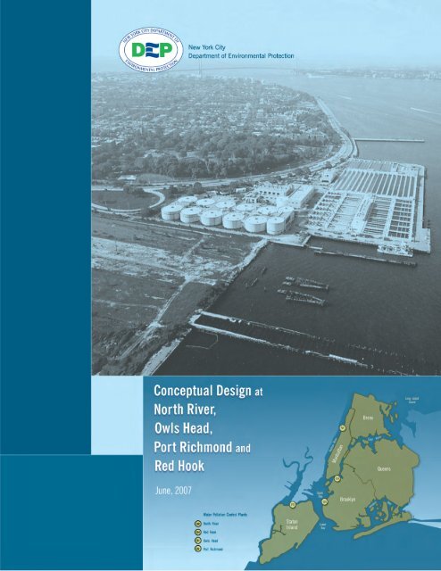
Harbor Estuary Program<br />
Port Richmond<br />
Water Pollution Control Plant<br />
Conceptual Design Report<br />
June 2007<br />
DRAFT
Harbor Estuary Program June 2007<br />
Port Richmond Water Pollution Control Plant<br />
DRAFT<br />
TABLE OF CONTENTS<br />
Section Description Page<br />
1 PORT RICHMOND WATER POLLUTION CONTROL PLANT 1-1<br />
1.1 BACKGROUND 1-1<br />
1.2 EXISTING CONDITIONS 1-1<br />
1.2.1 Plant Hydraulics 1-2<br />
1.2.2 Influent Screening and Main Sewage Pumping 1-5<br />
1.2.3 Primary Settling 1-6<br />
1.2.4 Primary Sludge Pumping and Degritting 1-8<br />
1.2.5 Aeration 1-9<br />
1.2.6 Final Settling Tanks 1-12<br />
1.2.7 Disinfection and Outfall 1-13<br />
1.2.8 Return Activated Sludge 1-16<br />
1.2.9 Waste Activated Sludge/Mixed Liquor 1-16<br />
1.2.10 Sludge Thickening and Elutriation 1-16<br />
1.2.11 Anaerobic Digestion 1-20<br />
1.2.12 Sludge Storage and Transfer 1-23<br />
1.2.13 Summary of Plant Operations 1-23<br />
1.3 ONGOING AND PLANNED UPGRADES 1-29<br />
2 MASS BALANCE DIAGRAMS 2-1<br />
3 BASIS OF DESIGN 3-1<br />
4 EXISTING CONDITIONS WITH SOLIDS FILTRATION 4-1<br />
4.1 PRIMARY SETTLING TANKS 4-1<br />
4.2 FINE SCREENS 4-1<br />
4.3 AERATION TANKS 4-1<br />
4.3.1 Flow Distribution and Control 4-1<br />
4.3.2 Baffles and Zone Sizing 4-1<br />
4.3.3 Anoxic Zone Mixers 4-1<br />
4.3.4 Air Distribution and Control 4-1<br />
4.3.5 Diffusers 4-2<br />
4.4 PROCESS AERATION SYSTEM 4-2<br />
4.5 FINAL SETTLING TANKS 4-2<br />
4.6 RETURN ACTIVATED SLUDGE SYSTEM 4-2<br />
4.7 WASTE ACTIVATED SLUDGE SYSTEM 4-2<br />
4.8 FROTH CONTROL 4-2<br />
4.8.1 Froth Control Hoods 4-2<br />
4.8.2 RAS Chlorination 4-2<br />
4.8.3 Surface Wasting 4-3<br />
4.9 CHEMICAL FACILITIES 4-3<br />
4.9.1 Alkalinity 4-3<br />
4.9.2 Carbon 4-3<br />
TOC-1
Harbor Estuary Program June 2007<br />
Port Richmond Water Pollution Control Plant<br />
DRAFT<br />
4.10 INTERMEDIATE PUMPING STATION 4-3<br />
4.11 TERTIARY TREATMENT 4-3<br />
4.11.1 Solids Filtration 4-3<br />
4.11.2 Microfiltration/Ultrafiltration 4-4<br />
4.11.3 Denitrification Filters 4-4<br />
4.12 MEMBRANE BIOREACTORS 4-4<br />
4.13 ODOR CONTROL 4-5<br />
5 EXISTING CONDITIONS WITH MICROFILTRATION/ULTRAFILTRATION 5-1<br />
5.1 PRIMARY SETTLING TANKS 5-1<br />
5.2 FINE SCREENS 5-1<br />
5.3 AERATION TANKS 5-2<br />
5.3.1 Flow Distribution and Control 5-2<br />
5.3.2 Baffles and Zone Sizing 5-2<br />
5.3.3 Anoxic Zone Mixers 5-2<br />
5.3.4 Air Distribution and Control 5-2<br />
5.3.5 Diffusers 5-2<br />
5.4 PROCESS AERATION SYSTEM 5-2<br />
5.5 FINAL SETTLING TANKS 5-2<br />
5.6 RETURN ACTIVATED SLUDGE SYSTEM 5-2<br />
5.7 WASTE ACTIVATED SLUDGE SYSTEM 5-2<br />
5.8 FROTH CONTROL 5-2<br />
5.8.1 Froth Control Hoods 5-3<br />
5.8.2 RAS Chlorination 5-3<br />
5.8.3 Surface Wasting 5-3<br />
5.9 CHEMICAL FACILITIES 5-3<br />
5.9.1 Alkalinity 5-3<br />
5.9.2 Carbon 5-3<br />
5.10 INTERMEDIATE PUMPING STATION 5-3<br />
5.11 TERTIARY TREATMENT 5-3<br />
5.11.1 Solids Filtration 5-3<br />
5.11.2 Microfiltration/Ultrafiltration 5-4<br />
5.11.3 Denitrification Filters 5-5<br />
5.12 MEMBRANE BIOREACTORS 5-5<br />
5.13 ODOR CONTROL 5-5<br />
6 ADVANCED BASIC BNR 6-1<br />
6.1 PRIMARY SETTLING TANKS 6-1<br />
6.2 FINE SCREENS 6-1<br />
6.3 AERATION TANKS 6-1<br />
6.3.1 Flow Distribution and Control 6-1<br />
6.3.2 Baffles and Zone Sizing 6-2<br />
6.3.3 Anoxic Zone Mixers 6-3<br />
6.3.4 Air Distribution and Control 6-4<br />
6.3.5 Diffusers 6-5<br />
6.4 PROCESS AERATION SYSTEM 6-6<br />
TOC-2
Harbor Estuary Program June 2007<br />
Port Richmond Water Pollution Control Plant<br />
DRAFT<br />
6.5 FINAL SETTLING TANKS 6-7<br />
6.6 RETURN ACTIVATED SLUDGE SYSTEM 6-7<br />
6.7 WASTE ACTIVATED SLUDGE SYSTEM 6-7<br />
6.8 FROTH CONTROL 6-8<br />
6.8.1 Froth Control Hoods 6-8<br />
6.8.2 RAS Chlorination 6-9<br />
6.8.3 Surface Wasting 6-10<br />
6.9 CHEMICAL FACILITIES 6-10<br />
6.9.1 Alkalinity 6-10<br />
6.9.2 Carbon 6-11<br />
6.10 INTERMEDIATE PUMPING STATION 6-11<br />
6.11 TERTIARY TREATMENT 6-11<br />
6.11.1 Solids Filtration 6-11<br />
6.11.2 Microfiltration/Ultrafiltration 6-11<br />
6.11.3 Denitrification Filters 6-11<br />
6.12 MEMBRANE BIOREACTORS 6-12<br />
6.13 ODOR CONTROL 6-12<br />
7 FULL STEP BNR 7-1<br />
7.1 PRIMARY SETTLING TANKS 7-1<br />
7.2 FINE SCREENS 7-1<br />
7.3 AERATION TANKS 7-1<br />
7.3.1 Flow Distribution and Control 7-1<br />
7.3.2 Baffles and Zone Sizing 7-1<br />
7.3.3 Anoxic Zone Mixers 7-2<br />
7.3.4 Air Distribution and Control 7-3<br />
7.3.5 Diffusers 7-3<br />
7.4 PROCESS AERATION SYSTEM 7-4<br />
7.5 FINAL SETTLING TANKS 7-4<br />
7.6 RETURN ACTIVATED SLUDGE SYSTEM 7-5<br />
7.7 WASTE ACTIVATED SLUDGE SYSTEM 7-5<br />
7.8 FROTH CONTROL 7-5<br />
7.8.1 Froth Control Hoods 7-5<br />
7.8.2 RAS Chlorination 7-5<br />
7.8.3 Surface Wasting 7-5<br />
7.9 CHEMICAL FACILITIES 7-6<br />
7.9.1 Alkalinity 7-6<br />
7.9.2 Carbon 7-6<br />
7.10 INTERMEDIATE PUMPING STATION 7-7<br />
7.11 TERTIARY TREATMENT 7-7<br />
7.11.1 Solids Filtration 7-7<br />
7.11.2 Microfiltration/Ultrafiltration 7-7<br />
7.11.3 Denitrification Filters 7-7<br />
7.12 MEMBRANE BIOREACTORS 7-7<br />
7.13 ODOR CONTROL 7-7<br />
8 FULL STEP BNR WITH SOLIDS FILTRATION 8-1<br />
TOC-3
Harbor Estuary Program June 2007<br />
Port Richmond Water Pollution Control Plant<br />
DRAFT<br />
8.1 PRIMARY SETTLING TANKS 8-1<br />
8.2 FINE SCREENS 8-1<br />
8.3 AERATION TANKS 8-1<br />
8.3.1 Flow Distribution and Control 8-1<br />
8.3.2 Baffles and Zone Sizing 8-1<br />
8.3.3 Anoxic Zone Mixers 8-1<br />
8.3.4 Air Distribution and Control 8-1<br />
8.3.5 Diffusers 8-1<br />
8.4 PROCESS AERATION SYSTEM 8-1<br />
8.5 FINAL SETTLING TANKS 8-2<br />
8.6 RETURN ACTIVATED SLUDGE SYSTEM 8-2<br />
8.7 WASTE ACTIVATED SLUDGE SYSTEM 8-2<br />
8.8 FROTH CONTROL 8-2<br />
8.8.1 Froth Control Hoods 8-2<br />
8.8.2 RAS Chlorination 8-2<br />
8.8.3 Surface Wasting 8-2<br />
8.9 CHEMICAL FACILITIES 8-2<br />
8.9.1 Alkalinity 8-2<br />
8.9.2 Carbon 8-2<br />
8.10 INTERMEDIATE PUMPING STATION 8-3<br />
8.11 TERTIARY TREATMENT 8-3<br />
8.11.1 Solids Filtration 8-3<br />
8.11.2 Microfiltration/Ultrafiltration 8-3<br />
8.11.3 Denitrification Filters 8-3<br />
8.12 MEMBRANE BIOREACTORS 8-3<br />
8.13 ODOR CONTROL 8-3<br />
9 FULL STEP BNR WITH MICROFILTRATION/ULTRAFILTRATION 9-1<br />
9.1 PRIMARY SETTLING TANKS 9-1<br />
9.2 FINE SCREENS 9-1<br />
9.3 AERATION TANKS 9-1<br />
9.3.1 Flow Distribution and Control 9-1<br />
9.3.2 Baffles and Zone Sizing 9-1<br />
9.3.3 Anoxic Zone Mixers 9-1<br />
9.3.4 Air Distribution and Control 9-1<br />
9.3.5 Diffusers 9-1<br />
9.4 PROCESS AERATION SYSTEM 9-1<br />
9.5 FINAL SETTLING TANKS 9-2<br />
9.6 RETURN ACTIVATED SLUDGE SYSTEM 9-2<br />
9.7 WASTE ACTIVATED SLUDGE SYSTEM 9-2<br />
9.8 FROTH CONTROL 9-2<br />
9.8.1 Froth Control Hoods 9-2<br />
9.8.2 RAS Chlorination 9-2<br />
9.8.3 Surface Wasting 9-2<br />
9.9 CHEMICAL FACILITIES 9-2<br />
9.9.1 Alkalinity 9-2<br />
TOC-4
Harbor Estuary Program June 2007<br />
Port Richmond Water Pollution Control Plant<br />
DRAFT<br />
9.9.2 Carbon 9-3<br />
9.10 INTERMEDIATE PUMPING STATION 9-3<br />
9.11 TERTIARY TREATMENT 9-3<br />
9.11.1 Solids Filtration 9-3<br />
9.11.2 Microfiltration/Ultrafiltration 9-3<br />
9.11.3 Denitrification Filters 9-3<br />
9.12 MEMBRANE BIOREACTORS 9-3<br />
9.13 ODOR CONTROL 9-3<br />
10 FULL STEP BNR WITH DENITRIFICATION FILTERS 10-1<br />
10.1 PRIMARY SETTLING TANKS 10-1<br />
10.2 FINE SCREENS 10-1<br />
10.3 AERATION TANKS 10-1<br />
10.3.1 Flow Distribution and Control 10-1<br />
10.3.2 Baffles and Zone Sizing 10-1<br />
10.3.3 Anoxic Zone Mixers 10-1<br />
10.3.4 Air Distribution and Control 10-1<br />
10.3.5 Diffusers 10-1<br />
10.4 PROCESS AERATION SYSTEM 10-1<br />
10.5 FINAL SETTLING TANKS 10-2<br />
10.6 RETURN ACTIVATED SLUDGE SYSTEM 10-2<br />
10.7 WASTE ACTIVATED SLUDGE SYSTEM 10-2<br />
10.8 FROTH CONTROL 10-2<br />
10.8.1 Froth Control Hoods 10-2<br />
10.8.2 RAS Chlorination 10-2<br />
10.8.3 Surface Wasting 10-2<br />
10.9 CHEMICAL FACILITIES 10-2<br />
10.9.1 Alkalinity 10-2<br />
10.9.2 Carbon 10-2<br />
10.10 INTERMEDIATE PUMPING STATION 10-3<br />
10.11 TERTIARY TREATMENT 10-3<br />
10.11.1 Solids Filtration 10-3<br />
10.11.2 Microfiltration/Ultrafiltration 10-3<br />
10.11.3 Denitrification Filters 10-3<br />
10.12 MEMBRANE BIOREACTORS 10-4<br />
10.13 ODOR CONTROL 10-4<br />
11 MEMBRANE BIOREACTORS 11-1<br />
11.1 PRIMARY SETTLING TANKS 11-1<br />
11.2 FINE SCREENS 11-1<br />
11.3 AERATION TANKS 11-2<br />
11.3.1 Flow Distribution and Control 11-2<br />
11.3.2 Baffles and Zone Sizing 11-3<br />
11.3.3 Anoxic Zone Mixers 11-3<br />
11.3.4 Air Distribution and Control 11-4<br />
11.3.5 Diffusers 11-4<br />
TOC-5
Harbor Estuary Program June 2007<br />
Port Richmond Water Pollution Control Plant<br />
DRAFT<br />
11.4 PROCESS AERATION SYSTEM 11-5<br />
11.5 FINAL SETTLING TANKS 11-5<br />
11.6 RETURN ACTIVATED SLUDGE SYSTEM/INTERNAL RECYCLE 11-6<br />
11.7 WASTE ACTIVATED SLUDGE SYSTEM 11-6<br />
11.8 FROTH CONTROL 11-6<br />
11.8.1 Froth Control Hoods 11-6<br />
11.8.2 RAS Chlorination 11-7<br />
11.8.3 Surface Wasting 11-7<br />
11.9 CHEMICAL FACILITIES 11-7<br />
11.9.1 Alkalinity 11-7<br />
11.9.2 Carbon 11-7<br />
11.10 INTERMEDIATE PUMPING STATION 11-7<br />
11.11 TERTIARY TREATMENT 11-7<br />
11.11.1 Solids Filtration 11-7<br />
11.11.2 Microfiltration/Ultrafiltration 11-7<br />
11.11.3 Denitrification Filters 11-7<br />
11.12 MEMBRANE BIOREACTORS 11-8<br />
11.13 ODOR CONTROL 11-9<br />
12 SUMMARY OF COST AND PERFORMANCE 12-1<br />
APPENDIX A<br />
APPENDIX B<br />
I<br />
XXIX<br />
TOC-6
Harbor Estuary Program June 2007<br />
Port Richmond Water Pollution Control Plant<br />
DRAFT<br />
TABLE OF FIGURES<br />
Figure Description Page<br />
Figure 1-1: Overall Plant Flow Schematic................................................................................... 1-2<br />
Figure 1-2: Plant Hydraulic Profile.............................................................................................. 1-3<br />
Figure 1-3: MSP and Influent Screening Process Overview ....................................................... 1-6<br />
Figure 1-4: Primary Settling Tank Schematic Overview............................................................. 1-8<br />
Figure 1-5: Aeration Tank Flow Schematic............................................................................... 1-10<br />
Figure 1-6: Average Aerator MLSS Concentrations ................................................................. 1-11<br />
Figure 1-7: Schematic Overview of Chlorination Facilities...................................................... 1-14<br />
Figure 1-8: Arrangement of the Sludge Thickening Facilities .................................................. 1-17<br />
Figure 1-9: Mass Balance on Elutriators ................................................................................... 1-19<br />
Figure 1-10: Mass Balance on Sludge Thickening.................................................................... 1-20<br />
Figure 1-11: Schematic of the Digestion Process ...................................................................... 1-21<br />
Figure 11-1: MBR Setup............................................................................................................ 11-9<br />
TOC-7
Harbor Estuary Program June 2007<br />
Port Richmond Water Pollution Control Plant<br />
DRAFT<br />
TABLE OF TABLES<br />
Table Description Page<br />
Table 1-1: Port Richmond Design Flows..................................................................................... 1-2<br />
Table 1-2: Summary of Wet Weather Flows and Bypasses ........................................................ 1-4<br />
Table 1-3: Unit Process Maximum Treatment Capacities........................................................... 1-5<br />
Table 1-4: MSP and Influent Screening Design Criteria ............................................................. 1-6<br />
Table 1-5: Primary Settling Tank Design Criteria....................................................................... 1-8<br />
Table 1-6: Primary Sludge Pumping and Degritting Design Criteria.......................................... 1-9<br />
Table 1-7: Aeration System Design Criteria.............................................................................. 1-11<br />
Table 1-8: Aeration System Operating Parameters ................................................................... 1-12<br />
Table 1-9: Final Settling Tank Design Criteria.......................................................................... 1-13<br />
Table 1-10: Disinfection System Design Criteria...................................................................... 1-15<br />
Table 1-11: RAS Pump Design Criteria .................................................................................... 1-16<br />
Table 1-12: Sludge Thickening System Design Criteria ........................................................... 1-18<br />
Table 1-13: Digester System Design Criteria ............................................................................ 1-22<br />
Table 1-14: Anaerobic Digester Performance ........................................................................... 1-23<br />
Table 1-15: Port Richmond WPCP Existing Facility Description............................................. 1-23<br />
Table 6-1: Operating Flow Distribution Assumptions for ABBNR ............................................ 6-1<br />
Table 6-2: Anticipated Inter-Zone Baffle Wall Locations for ABBNR ...................................... 6-2<br />
Table 6-3: Anticipated Mixed Liquor Concentrations for ABBNR ............................................ 6-4<br />
Table 6-4: Anticipated Mixing Zone Sizing (per tank) for ABBNR ........................................... 6-4<br />
Table 6-5: Anticipated Number of Anoxic Zone Mixers for ABBNR ........................................ 6-4<br />
Table 6-6: Diffuser Requirements for ABBNR ........................................................................... 6-6<br />
Table 6-7: Future 2045 Air Requirements for ABBNR............................................................... 6-6<br />
Table 7-1: Operating Flow Distribution Assumptions for FSBNR ............................................. 7-1<br />
Table 7-2: Anticipated Inter-Zone Baffle Wall Locations for FSBNR ....................................... 7-2<br />
Table 7-3: Anticipated Mixed Liquor Concentrations for FSBNR ............................................. 7-2<br />
Table 7-4: Anticipated Mixing Zone Sizing (per tank) for FSBNR ............................................ 7-2<br />
Table 7-5: Anticipated Number of Anoxic Zone Mixers for FSBNR ......................................... 7-3<br />
Table 7-6: Diffuser Requirements for FSBNR ............................................................................ 7-4<br />
Table 7-7: Future 2045 Air Requirements for FSBNR................................................................ 7-4<br />
TOC-8
Harbor Estuary Program June 2007<br />
Port Richmond Water Pollution Control Plant<br />
DRAFT<br />
Table 11-1: Operating Flow Distribution Assumptions for MBR ............................................. 11-3<br />
Table 11-2: Anticipated Inter-Zone Baffle Wall Locations for MBR ....................................... 11-3<br />
Table 11-3: Anticipated Mixed Liquor Concentrations for MBR ............................................. 11-3<br />
Table 11-4: Anticipated Mixing Zone Sizing (per tank) for MBR............................................ 11-4<br />
Table 11-5: Anticipated Number of Anoxic Zone Mixers for MBR ......................................... 11-4<br />
Table 11-6: Diffuser Requirements for MBR............................................................................ 11-5<br />
Table 11-7: Future 2045 Air Requirements for MBR ............................................................... 11-5<br />
Table 12-1: Secondary Effluent for Each Level of Technology................................................ 12-1<br />
Table 12-2: Capital Construction Costs for Levels of Treatment.............................................. 12-1<br />
TOC-9
Harbor Estuary Program June 2007<br />
Port Richmond Water Pollution Control Plant<br />
DRAFT<br />
1 PORT RICHMOND WATER POLLUTION CONTROL PLANT<br />
1.1 Background<br />
The Port Richmond Water Pollution Control Plant (WPCP) is a 60 million gallon per day (mgd)<br />
design dry weather flow, 120 mgd peak wet weather flow, facility located on the northern side of<br />
Staten Island. It was built in 1953 and services 9,665 acres in the Northern section of Staten<br />
Island, including the communities of Howland Hock, Arlington, Old Place, Marnier's Harbor,<br />
Port Ivory, Graniteville, Port Richmond, Westerleigh, Livingston, Elm Park, West <strong>New</strong><br />
Brighton, Silver Lake, St. George, Ward Hill, Stapleton, Grymes Hill, Clifton, Fox Hills,<br />
Rosebank, Shore Acres, Bloomfield, Chelsea, Travis, Bulls Head, Emerson Hill, Concord,<br />
Grasmere, and Arrochar. It is located at 1801 Richmond Terrace, Staten Island, NY, 10310 in<br />
Staten Island, <strong>New</strong> <strong>York</strong>. The site is adjacent to the Kill Van Kull, leading into the Upper <strong>New</strong><br />
<strong>York</strong> Bay, located between Clove Road and Taylor Street.<br />
The Port Richmond WPCP has been providing full secondary treatment since 1979. Processes<br />
include primary screening, raw sewage pumping, grit removal and primary settling, air activated<br />
sludge capable of operating in the step aeration mode, final settling, and chlorine disinfection.<br />
The Port Richmond WPCP has a design dry weather flow (DDWF) capacity of 60 mgd, and is<br />
designed to receive a maximum flow of 120 mgd (2 times DDWF) with 90 mgd (1.5 times<br />
DDWF) receiving secondary treatment. Flows over 90 mgd receive primary treatment and<br />
disinfection. The daily average flow during 2004 was 35 mgd, with a dry weather flow average<br />
of 32 mgd. During severe wet weather events in 2004 the plant treated 97 to 109 mgd<br />
1.2 Existing Conditions<br />
The Port Richmond WPCP is a secondary treatment plant that provides preliminary screening,<br />
primary settling, biological treatment through a step-feed activated sludge process, secondary<br />
settling and disinfection. The combined primary and waste activated sludge flow is gravity<br />
thickened, anaerobically digested, elutriated, and transferred offsite for dewatering and centrate<br />
treatment. Figure 1-1 includes an overall plant layout and general flow pattern.<br />
1-1
Harbor Estuary Program June 2007<br />
Port Richmond Water Pollution Control Plant<br />
DRAFT<br />
1.2.1 Plant Hydraulics<br />
Figure 1-1: Overall Plant Flow Schematic<br />
A plant hydraulic profile is included as Figure 1-2. Port Richmond is sized for a maximum<br />
influent flow of 160 mgd with one primary settling tank (PST), one aeration tank (AT), and one<br />
final settling tank (FST) out of service. Table 1-1 shows the dry and wet weather design flows<br />
for Port Richmond.<br />
Table 1-1: Port Richmond Design Flows<br />
Port Richmond Plant Capacity<br />
Design Dry Weather Flow<br />
60 mgd<br />
Design Wet Weather Flow<br />
120 mgd<br />
1-2
Harbor Estuary Program June 2007<br />
Port Richmond Water Pollution Control Plant<br />
DRAFT<br />
Figure 1-2: Plant Hydraulic Profile<br />
Raw sewage flow from the influent sewer separates intro three channels, each equipped with a 5-<br />
foot wide stop gate and a dedicated, mechanically-cleaned bar screen. Screened sewage then<br />
splits into two channels. Flow in each channel passes through two 72-inch diameter sluice gates<br />
in separate 72-inch main sewage pumps (MSP) suction headers. Three vertical centrifugal<br />
pumps are connected to each of the two headers and lift the sewage to the primary settling tank<br />
influent channel which allows flow by gravity through the remainder of the plant.<br />
The four primary settling tanks each have two bays, and each bay is fed by the influent conduit<br />
via three 42-inch sluice gates. Primary settling tanks effluent flows into a 9-foot wide primary<br />
effluent channel before discharging into a 96-inch diameter pipe that transports flow to the<br />
aeration tank influent channel.<br />
Stop logs and a manually-operated electromechanical butterfly gate is used to direct primary<br />
effluent flow greater than 90 mgd to the bypass channel. Operations staff estimate that 10<br />
percent of wet weather events require use of the bypass channel. The bypass channel splits into<br />
two 60-inch pipes prior to entering the final settling tank effluent channel upstream of the<br />
Parshall flume.<br />
Primary effluent enters the aeration tank influent chamber where it mixes with thickener and<br />
elutriator overflow before being distributed between two aeration tank influent channels located<br />
at the East and West ends of the aeration tanks. One influent channel feeds passes A and C of<br />
each tank, while the other channel feeds passes B and D. Each pass can receive primary effluent<br />
1-3
Harbor Estuary Program June 2007<br />
Port Richmond Water Pollution Control Plant<br />
DRAFT<br />
through two 48 by 72 inch motor operated sluice gates. The tanks are operated in step-feed<br />
mode.<br />
RAS is pumped to a trapezoidal return sludge channel from which it enters sludge sight wells<br />
located at the upstream end of pass A of each aeration tank through two 24-inch square sluice<br />
gates. Flow exits the aeration tanks through two 36 by 60 inch sluice gates located at the effluent<br />
end of Pass D. Aeration tank connections to the final settling tank influent distribution channels<br />
are somewhat asymmetric.<br />
Aeration tank mixed liquor is fed to the final settling tanks from two 8-foot wide final settling<br />
tank influent channels through six 3 by 3 foot slide gates per tank. Sludge in each tank is<br />
collected via a flight-and-chain mechanism to a center channel, and is then moved by a cross<br />
collector to two hoppers. RAS is drained by each hopper through variable elevation bell weirs<br />
and fed into one of two 30-inch diameter RAS pipes. These pipes discharge by gravity into a<br />
RAS wet well.<br />
The secondary effluent discharges through a Parshall flume into a 6-foot wide chlorine contact<br />
tank influent channel. The influent channel discharges into two separate chlorine contact tanks<br />
through four 48 by 60 inch sluice gates (two gates per tank).<br />
After traveling over the chlorine contact tank weirs, flow leaves the plant through the 96-inch<br />
plant outfall. The outfall is 524 feet long and terminates in a large headwall.<br />
The 24-inch diameter plant drain receives recycle streams from throughout the plant and<br />
discharges just downstream of the bar screens. Recycle flows include tank overflows, unit<br />
process tank drains, and final settling tank skimmings. Skimmings pit underflow and degritted<br />
primary sludge wet well overflow are also returned downstream of the bar screens via a 10-inch<br />
diameter pipe.<br />
The plant is permitted to accept up to 120 mgd, or two times the 60 mgd Design Dry Weather<br />
Flow capacity. Wet weather flows in excess of 90 mgd, as measured by the MSP meters,<br />
receives primary settling and disinfection. Table 1-2 summarizes wet weather flows and bypass<br />
during the two-year study period of November 1999 through October 2001.<br />
Table 1-2: Summary of Wet Weather Flows and Bypasses<br />
Description<br />
Value<br />
Design Dry Weather Flow (mgd) 60<br />
Maximum Hourly Flow (mgd) 130<br />
Maximum Daily Flow (mgd) 104<br />
Percent of Days Bypass was Required 9.7<br />
Average Flow to Bypass Channel When Required (mgd) 3.0<br />
While the plant is permitted to handle up to 120 mgd, many of the process units were designed<br />
for higher flow rates, as presented in Table 1-3.<br />
1-4
Harbor Estuary Program June 2007<br />
Port Richmond Water Pollution Control Plant<br />
DRAFT<br />
Table 1-3: Unit Process Maximum Treatment Capacities<br />
Unit Process<br />
Maximum Capacity (mgd)<br />
Headworks 160<br />
MSPs 180<br />
Primary Settling Tanks 122<br />
Chlorine Contact Tanks 156<br />
Plant Outfall At Least 160<br />
Secondary Bypass 40<br />
1.2.2 Influent Screening and Main Sewage Pumping<br />
Raw sewage flow from the influent sewer separates into three channels, each equipped with a 5-<br />
foot wide isolation sluice gate. The influent channels are flushed daily to minimize grit<br />
accumulation. Each influent channel has a dedicated, mechanically-cleaned bar screen. Each<br />
bar screen cleaner is powered by a submersible motor enclosure. The current units replaced the<br />
bar-and-rack units in 1994. The bar screens empty into nearby satellite containers, which are<br />
periodically transferred to a common 20 or 26 cubic yard disposal container using a forklift.<br />
Under normal conditions, one bar screen and channel are used. A second channel and screen are<br />
used during wet weather events. After screening, the three channels combine into a common<br />
channel.<br />
Screened sewage then enters into two 72-inch main sewage pump (MSP) suction headers<br />
through two 72-inch sluice gates. Three pumps are connected to each of the two headers to lift<br />
the sewage to the raw sewage plenum. The MSPs are of the vertical, non-clogging, centrifugal,<br />
mixed flow type and are manually controlled to maintain a constant water surface elevation.<br />
Pumps operate at speeds varying between 70 to 97 percent of the maximum speed, resulting in<br />
pumping rates between 17 and 30 mgd. Under normal conditions, one pump is operated at night,<br />
two are operated during the day, and four are operated during rain events. The MSPs have<br />
pumped over 120 mgd during rain events. MSP seal water (city water) is provided by a system<br />
including a 300-gallon seal water tank and two 60-gpm pumps.<br />
The screenings removal rate is calculated based on the number of 20 and 26 cubic yard<br />
containers removed. However, both screenings and grit accumulate in these containers, and it is<br />
assumed that each of these sources occupy 50 percent of the total container volume.<br />
Raw influent samples are collected from the primary influent channel on an hourly basis by an<br />
automatic sampler, which composites them once daily. Primary influent flow is measured by<br />
strap-on Doppler flow meters located on the discharge of each MSP. These flow measurements<br />
were utilized for plant reporting prior to installation of the Parshall flume at the final settling tank<br />
effluent in 1988.<br />
Table 1-4 lists design criteria for these unit processes and Figure 1-3 provides a schematic<br />
overview of these processes.<br />
1-5
Harbor Estuary Program June 2007<br />
Port Richmond Water Pollution Control Plant<br />
DRAFT<br />
Table 1-4: MSP and Influent Screening Design Criteria<br />
Parameter<br />
Value<br />
Number of Bar Screens 3<br />
• Width (ft) 5<br />
• Clear Opening (in) 7/8<br />
• Inclination from Horizontal (degrees) 84<br />
Number of MSPs 6<br />
• Type Mixed Flow, Centrifugal<br />
• Pump Speed (rpm) 500 – 585<br />
• Capacity (mgd) 17 – 30<br />
• TDH (ft) 34 -38.5<br />
• Motor Horsepower (hp) 250<br />
Number of Ring Flush Pumps 2<br />
• Type Mixed Flow, Centrifugal<br />
• Pump Speed (rpm) 900<br />
• Capacity (gpm) 470<br />
• TDH (ft) 43<br />
• Motor Horsepower (hp) 15<br />
1.2.3 Primary Settling<br />
Figure 1-3: MSP and Influent Screening Process Overview<br />
1-6
Harbor Estuary Program June 2007<br />
Port Richmond Water Pollution Control Plant<br />
DRAFT<br />
The Port Richmond WPCP has four rectangular primary settling tanks with two bays each. The<br />
primary settling tanks are not symmetric about the MSP discharge plenum, which is located<br />
along the influent end of primary settling tanks 1 and 2. Both bays of each primary settling tank<br />
are fed from the influent conduit through three 42-inch square sluice gates. Primary settling<br />
tanks are taken out of service on an as-needed basis for cleaning and maintenance.<br />
The primary settling tanks are equipped with influent channel aeration, conventional chain and<br />
flight sludge collectors/surface skimmers, inlet baffles and adjustable overflow weirs. The<br />
influent channel is aerated to prevent deposition of raw sewage and grit and to prevent a buildup<br />
of floatables on the surface. Each primary settling tank has two longitudinal chain and flight<br />
sludge collectors/surface skimmers (one per bay) and one screw-type cross collector.<br />
The chain and flight collectors skim the surface to convey skimmings to a dipping weir at the<br />
downstream end of the primary settling tanks. Skimmings removal is initiated manually by<br />
visual inspection. The skimmings dipper discharges to an open channel that discharges to two<br />
pits located next to the primary settling tanks. The two skimmings pits both discharge to a<br />
common decanting pit. Several hours after a skimmings pit is filled, a telescoping subnatant<br />
valve is lowered slowly to transfer excess skimmings carrier liquid to the decanting pit. An<br />
overhead crane then lowers a 7 cubic foot clamshell bucket into the skimmings pit to lift<br />
concentrated skimmings to 6 cubic foot disposal containers, which are disposed of offsite. The<br />
skimmings pit underflow is continuously drained and returned to the head of the plant.<br />
Primary influent flow is measured by strap-on Doppler flow meters. Raw influent samples are<br />
taken from the primary influent channel. Samples are also taken from the primary effluent<br />
channel six times a day, five days per week and composited at the end of each day. Flow<br />
bypassing in the secondary system is measured using a Parshall flume, equipped with an<br />
ultrasonic level sensor. The sensor records measurements in a data logger that needs to be<br />
regularly downloaded.<br />
Current surface overflow rates are within typical design standards. The plant’s design surface<br />
overflow rate of 1,970 gpd/ft 2 is consistent with the <strong>New</strong> <strong>York</strong> City design criteria of 2,000<br />
gpd/ft 2 . Current weir overflow rates of 28,400 gpd/ft exceed typical design standards (such as<br />
15,000 gpd/ft for the Ten States Standard), but are within the plant’s design value of 50,500<br />
gpd/ft. <strong>New</strong> <strong>York</strong> City design criteria for surface overflow and weir overflow are significantly<br />
higher than industry design standards.<br />
Table 1-5 includes primary settling tank design criteria. Figure 1-4 is a schematic overview of<br />
the primary settling tank unit process.<br />
1-7
Harbor Estuary Program June 2007<br />
Port Richmond Water Pollution Control Plant<br />
DRAFT<br />
Table 1-5: Primary Settling Tank Design Criteria<br />
Parameter<br />
Value<br />
Number of primary settling tanks 4<br />
• Number of Bays per Tank 2<br />
• Length (ft) 186<br />
• Width per Tank (ft) 41<br />
• Average Side Water Depth (ft) 12<br />
• Total Surface Area - All Tanks ( ft 2 ) 30,504<br />
• Weir Length – All Tanks (ft) 1,188<br />
Number of Skimmings Pits 2<br />
• Maximum Length (ft) 6<br />
• Maximum Width (ft) 6<br />
• Maximum Depth (ft) 14<br />
• Volume Per Well (ft 3 ) 480<br />
Figure 1-4: Primary Settling Tank Schematic Overview<br />
1.2.4 Primary Sludge Pumping and Degritting<br />
Primary sludge is conveyed by chain and flight mechanisms in each primary settling tank bay<br />
into a collector channel and then by a cross collector into a common sludge sump pit for each<br />
tank. Six primary sludge pumps, located in the primary tank gallery, are operated continuously<br />
to prevent sludge blanket buildup in the primary settling tanks. The pumps are organized in<br />
series of three, with pumps 1-3 dedicated to primary settling tanks 1 and 2 and pumps 4-6<br />
1-8
Harbor Estuary Program June 2007<br />
Port Richmond Water Pollution Control Plant<br />
DRAFT<br />
dedicated to primary settling tanks 3 and 4. Generally, two pumps per set are in service while<br />
the other two are in standby. Occasionally, one pump per set is operated. The primary sludge<br />
pumps were replaced in 1988; each pump generally operates at 600 gpm.<br />
Primary sludge is pumped to five cyclone/classifier units. Normally, one unit is dedicated to<br />
each operating sludge pump, with an extra unit in standby. Each cyclone discharges to one<br />
washer/classifier. The cyclone degritters are sized to remove grit of 150 mesh and larger. The<br />
washer/classifiers currently do not use wash water. Each washer/classifier discharges into 1.5<br />
cubic yard satellite containers, which are transferred into nominal 20 and 26 cubic yard<br />
containers, where they are combined with screenings and hauled off site.<br />
Degritted primary sludge passes through a secondary screen and flows by gravity into a wet well,<br />
where it is pumped by three centrifugal pumps (one duty and two standby) to the gravity<br />
thickener distribution box. The overflow pipe from this wet well drains to the headworks just<br />
downstream of the bar screens.<br />
Primary sludge flow is neither metered nor sampled. Grit is measured by the number of 20 and<br />
26 cubic yard boxes that are filled.<br />
Table 1-6 provides primary sludge pumping and degritting design criteria.<br />
Table 1-6: Primary Sludge Pumping and Degritting Design Criteria<br />
Parameter<br />
Value<br />
Number of Primary Sludge Pumps<br />
6 (4 duty, 2 standby)<br />
• Type Torque-Flow<br />
• Capacity (gpm) 300 @ 76 ft, 600 @ 65 ft<br />
• TDH (ft) 65 - 76<br />
• Unit HP (hp) 30<br />
Number of Classifiers<br />
5 (4 duty, 1 standby)<br />
• Classifier Type Rake<br />
• Number of Cyclones per Classifier 1<br />
• Cyclone Capacity, Each (gpm) 550<br />
• Design Grit Removal Mesh Size 150<br />
Number of Degritted Primary Sludge Pumps<br />
3 (1 duty, 2 standby)<br />
• Type Centrifugal – Mixed Flow<br />
• Capacity (gpm) 1,300<br />
• TDH (ft) 44<br />
• Unit HP (hp) 50<br />
1.2.5 Aeration<br />
The aeration system consists of four aeration tanks, each comprised of four passes arranged in a<br />
serpentine manner. Primary effluent enters the aeration tank influent chamber where it mixes<br />
with gravity thickener and elutriator overflow and is distributed to one of the two influent<br />
channels. The tanks operate via the step-feed aeration process; primary effluent can enter any of<br />
1-9
Harbor Estuary Program June 2007<br />
Port Richmond Water Pollution Control Plant<br />
DRAFT<br />
the four passes through two 72 by 48 inch motor operated sluice gates, located at the head end of<br />
each pass. Primary effluent is designed to be evenly distributed to passes B, C, and D. Return<br />
Activated Sludge (RAS) is pumped to a return sludge channel, from which it enters pass A of the<br />
aeration tanks. Aerator effluent is discharged from pass D through two 36 by 68 inch motor<br />
operated sluice gates per tank and flows to the final settling tank influent channel. An aeration<br />
tank flow schematic is presented in Figure 1-5.<br />
Figure 1-5: Aeration Tank Flow Schematic<br />
Spray water is used to control frothing problems; it is only used approximately six times a year<br />
for a maximum of a week at a time. Process air is compressed by air blowers and discharged to a<br />
54-inch diameter common header. Port Richmond uses fine-pore ceramic tube diffusers which<br />
are currently being replaced in each aeration tank. Process air is also withdrawn from the main<br />
header to aerate the primary influent and effluent channels and the final settling tank influent<br />
channel. Dissolved oxygen levels are manually controlled by adjusting blower inlet guide vanes.<br />
Typically, one blower is operational and the remaining two are on standby. The fourth blower is<br />
not operational.<br />
Mixed liquor suspended solids (MLSS) concentrations are sampled at the midpoint of each pass<br />
once a day, four days a week. The four samples are composited, and reported as average aerator<br />
MLSS for each aeration tank. The aerator effluent MLSS is sampled from the end of Pass D of<br />
each aeration tank six times a day, four days a week, and composited at the end of each day.<br />
Dissolved oxygen concentrations at the end of Pass D of each aeration tank is monitored four<br />
times daily. Reported air flow rates are based on blower vane setting charts.<br />
1-10
Harbor Estuary Program June 2007<br />
Port Richmond Water Pollution Control Plant<br />
DRAFT<br />
Table 1-7 details design criteria for the aeration system.<br />
Table 1-7: Aeration System Design Criteria<br />
Parameter<br />
Value<br />
Number of Aeration Tanks 4<br />
• Number of Passes per Tank 4<br />
• Length (ft) 263<br />
• Width per Pass (ft) 26<br />
• Average Side Water Depth (ft) 17.4<br />
• Total Volume, All Tanks (MG) 14.2<br />
Number of Blowers 4<br />
• Rated Capacity (cfm) 24,000<br />
• Discharge Pressure (psig) 9<br />
• Unit HP (hp) 1,250<br />
• Diameter of Diffuser Tubes (in) 1.75<br />
• Number of Manifolds per Tank 296<br />
• Number of Diffuser Tubes per Tank 12,108<br />
• Average Height Above Bottom (ft) 2<br />
Figure 1-6 shows the average aerator MLSS concentration.<br />
Figure 1-6: Average Aerator MLSS Concentrations<br />
The plant typically operated with a mixed liquor concentration between 1,500 and 2,000 mg/L<br />
(with periods as high as 3,000 mg/L). The introduction of the Visy Paper load forced a reduction<br />
in operating MLSS concentrations, which decreased Nitrogen removal rates. Since March 1998,<br />
AEMLSS concentrations have been fairly constant.<br />
Port Richmond has a longer design HRT (5.7 hours) than most NYC plants (3-3.5 hours). The<br />
Solids Retention Time:<br />
1-11
Harbor Estuary Program June 2007<br />
Port Richmond Water Pollution Control Plant<br />
DRAFT<br />
V<br />
AT<br />
<br />
X<br />
AvgAer<br />
<br />
Q<br />
X <br />
<br />
Q Q <br />
WAS<br />
WAS<br />
Inf<br />
WAS<br />
X<br />
eff<br />
<br />
and Gould Sludge Age:<br />
V<br />
<br />
X<br />
<br />
<br />
Q<br />
AT<br />
AerInf<br />
X<br />
MLSS<br />
AerInf<br />
<br />
are within normal industry standards. The design Gould Sludge Age at Port Richmond is 3-6<br />
days, and the typical design for <strong>New</strong> <strong>York</strong> City plants is 3-5 days. The Visy Paper load forced a<br />
reduction in Gould Sludge Age from 10 to 15 days to only 4.2 days on average. Plant operations<br />
personnel target a minimum Dissolved Oxygen (DO) concentration of 5.0 mg/L in order to<br />
handle peak organic loads from Visy Paper. Table 1-8 details the aeration system operating<br />
parameters between November 1999 and October 2001.<br />
Table 1-8: Aeration System Operating Parameters<br />
Parameter Port Richmond<br />
Current<br />
Port Richmond<br />
Design<br />
NYCDEP Typical<br />
Design Standards<br />
Operations<br />
AEMLSS (mg/L) 890 3,900 1,500-2,500<br />
BOD 5 Loading<br />
(lb BOD 5 / 1000 ft 3 )<br />
21.9 45.2 50<br />
HRT, average (hr) 8.0 5.7 3-3.5<br />
HRT, min flow (hr) 10.1 - -<br />
HRT, max flow (hr) 3.4 - -<br />
SRT (days) 5 5-7 -<br />
Gould Sludge Age (days) 4.2 3-6 3-5<br />
F/M Ratio 0.48 0.25-0.5 0.25-0.33<br />
SVI (mL/g) 121 100 100<br />
Effluent DO (mg/L) 5.6 2.0-3.0 -<br />
Air Flow (mcf) 74.7 78.1 -<br />
1.2.6 Final Settling Tanks<br />
There are six final settling tanks, each of which is divided into three bays. Final settling tanks<br />
are equipped with sludge collectors, surface skimming mechanisms, inlet sluice gates, inlet<br />
baffles, and overflow weirs. Aeration tank effluent is fed to the final settling tanks by two sideby-side<br />
aerated final settling tank influent channels through two 3-foot square slide gates per<br />
bay. Flow is controlled by varying the inlet gate openings. Final settling tank effluent<br />
discharges over weirs into the final settling tank effluent channel.<br />
The plant currently takes waste sludge from the aerator effluent channel. The plant also has the<br />
capability to withdraw RAS from the final settling tanks using hydrostatic lifts. Sludge is<br />
collected by means of a chain and flight collector to a center channel, and is then moved by a<br />
cross collector to two hoppers. Each hopper has a hydrostatic lift pipe that collects RAS from a<br />
1-12
Harbor Estuary Program June 2007<br />
Port Richmond Water Pollution Control Plant<br />
DRAFT<br />
set of three final settling tanks and discharges into the RAS wet well. Skimmings are collected<br />
once per shift using the manually operated dipping weirs.<br />
Final settling tank effluent flow is measured by a Parshall flume, which has been used to report<br />
plant flows since January 1999. The secondary bypass enters the final settling tank effluent<br />
channel upstream of the Parshall flume.<br />
The Staten Island Infrastructure Study concluded that the Port Richmond final settling tanks are<br />
underloaded. The final settling tanks were operated at higher solids loading rates prior to the<br />
introduction of the Visy Paper load in 1997. The average solids loading rate on the final settling<br />
tanks during the infrastructure investigation was 3.8 pounds per square foot per day; plants are<br />
usually designed for a loading between 20 and 30 pounds per square foot per day. Table 1-9<br />
details final settling tank design criteria.<br />
Table 1-9: Final Settling Tank Design Criteria<br />
Parameter<br />
Value<br />
Number of Tanks 6<br />
Number of Bays Per Tank 3<br />
Length (ft) 298<br />
Width Per Tank (ft) 45<br />
Average Side Water Depth (ft) 10.8<br />
Total Volume, All Tanks (ft 3 ) 869,000<br />
Surface Area, All Tanks (ft 2 ) 80,460<br />
Weir Length, All Tanks (ft) 1,980<br />
1.2.7 Disinfection and Outfall<br />
A schematic of the chlorination facilities is shown in Figure 1-7<br />
1-13
Harbor Estuary Program June 2007<br />
Port Richmond Water Pollution Control Plant<br />
DRAFT<br />
Figure 1-7: Schematic Overview of Chlorination Facilities<br />
Disinfection is provided through chlorination of the final settling tank effluent. Each of two<br />
chlorine contact tanks is comprised of three passes. Two sluice gates control the influent to each<br />
tank. Chlorine tank effluent exits over weirs at the end of the third pass and enters the plant<br />
outfall that discharges to Kill Van Kull.<br />
The sodium hypochlorite (hypo) feed system is located in the sludge pumping and chlorination<br />
building and consists of three 12,000-gallon FRP storage tanks, three transfer pumps, three<br />
volumetric liquid feeders, and a dilution water system. Hypo solution is delivered at 15 percent<br />
concentration by truck. Hypo consumption increased considerably in 1997 with the introduction<br />
of the Visy paper load. There are two peristaltic hypo metering pumps and one centrifugal-type<br />
backup pump, which draw from a common header that serves all three storage tanks. One of the<br />
pumps constantly feeds chlorine to the RAS well to help control the growth of filamentous<br />
organisms. The other metering pump delivers chlorine to the three (two duty, one standby)<br />
volumetric feeders. The feeders are manually adjusted to achieve the target chlorine residual of<br />
1.3 mg/L. Any overflow from the return header of excess hypo solution is returned to the<br />
1-14
Harbor Estuary Program June 2007<br />
Port Richmond Water Pollution Control Plant<br />
DRAFT<br />
suction side of the hypo feed pumps. Two centrifugal pumps provide plant effluent water into<br />
which hypo is fed. There is also a 1,000-gallon emergency hypo tank adjacent to the final<br />
settling tank effluent channel which can be used in the event of a disinfection system<br />
interruption. This system, which is connected to emergency power, can dose final settling tank<br />
effluent for 8 to 12 hours.<br />
Plant data indicates average retention time in the chlorine contact tanks at 71.2 minutes, well<br />
beyond typical design standards. Table 1-10 details disinfection system design criteria.<br />
Table 1-10: Disinfection System Design Criteria<br />
Parameter<br />
Value<br />
Number of Chlorine Contact Tanks 2<br />
• Passes Per Tank 3<br />
• Length Per Pass (ft) 233.4<br />
• Width Per Pass (ft) 14<br />
• Average Side Water Depth (ft) 11.13<br />
• Total Volume, All Tanks (MG) 1.63<br />
• Weir Length, Per Tank (ft) 260<br />
Number of Hypo Tanks 3<br />
• Material FRP<br />
• Nominal Capacity, Each (gallons) 12,000<br />
• Diameter (ft) 12<br />
• Height (ft) 13.38<br />
Number of Hypo Transfer Pumps 2,1<br />
• Type Peristaltic, Centrifugal<br />
• Capacity, Each (gpm) 2.5<br />
• Discharge Pressure (psig) 10<br />
• Unit HP (hp) 0.75<br />
Number of Volumetric Feeders 3<br />
• Capacity, Each (gpm) 6.7<br />
• Unit HP (hp) 0.25<br />
Number of Dilution Water Pumps 2<br />
• Type Centrifugal<br />
• Capacity, Each (gpm) 6.7<br />
• TDH (ft) 35<br />
• Unit HP (hp) 7.5<br />
Plant Outfall Length (ft) 524<br />
• Diameter (in) 96<br />
Samples from the chlorine contact tank influent and effluent channels are collected hourly via<br />
sample pumps to monitor the influent and effluent chlorine residuals. Fecal Coliform samples<br />
are collected once per day from the effluent sample pump. A small amount of plant effluent is<br />
pumped from the chlorine contact tank effluent channel to the chlorination building, where it is<br />
collected by an auto-sampler.<br />
1-15
Harbor Estuary Program June 2007<br />
Port Richmond Water Pollution Control Plant<br />
DRAFT<br />
1.2.8 Return Activated Sludge<br />
Return Activated Sludge (RAS) is withdrawn from the final settling tanks. RAS is pumped from<br />
the wet well to a return sludge distribution channel by five centrifugal pumps, 3 constant speed<br />
and 2 variable speed. One constant speed pump and one variable speed pump are typically<br />
operated. From the distribution channel, return sludge enters eight sight wells located at the head<br />
of pass A of each aeration tank through two 24 X 24 inch sluice gates per sight well.<br />
RAS flow has been chlorinated for filamentous organism control since 1998. The RAS wet well<br />
overflow pipe discharges into the waste sludge wet well through a Kennison nozzle. The plant is<br />
not provided with a RAS flow meter. RAS is sampled six times per day, four days a week.<br />
Samples are typically taken from one of the RAS sight wells. The samples are composited at the<br />
end of the day.<br />
The maximum total RAS pump capacity is 32.8 mgd, which represents 55 percent of the design<br />
plant flow. This is not an operational problem given the plant receives approximately 50 percent<br />
of its design flow, but it should be noted that the RAS pump capacity is below current design<br />
standards.<br />
The RAS typically averages a 2,470 mg/L solids concentration. Table 1-11 details RAS pump<br />
design criteria.<br />
Table 1-11: RAS Pump Design Criteria<br />
Type Constant Speed Variable Speed<br />
Number 3 2<br />
• Capacity, Each (gpm) 5,700 3,750 to 5,700<br />
• TDH (ft) 13 13<br />
• Motor HP (hp) 30 30<br />
1.2.9 Waste Activated Sludge/Mixed Liquor<br />
The activated sludge process at Port Richmond is controlled by maintaining a target MLSS<br />
concentration and Gould sludge age. The waste sludge wet well receives waste mixed liquor,<br />
final settling tank underflow, and final settling tank effluent for thickener balance water.<br />
Currently, sludge is only wasted from the mixed liquor channel. The waste sludge and balance<br />
water mixture are pumped to the thickeners by three (one duty, two standby) horizontal, nonclog,<br />
variable speed, centrifugal waste sludge pumps. Only one pump is operating under normal<br />
conditions. The capacity of each pump is between 2,000 and 6,000 gallons per minute. Each<br />
pump is powered by a 50 horsepower motor, creating a total dynamic head of 20-39 feet.<br />
The waste mixed liquor line has a magnetic flow meter. The plant has no means of controlling<br />
or metering the balance water flow rate. The lack of flow metering makes process control and<br />
the development of accurate mass balances difficult.<br />
1.2.10 Sludge Thickening and Elutriation<br />
1-16
Harbor Estuary Program June 2007<br />
Port Richmond Water Pollution Control Plant<br />
DRAFT<br />
The plant has four tanks dedicated to gravity thickening and two smaller tanks for elutriation.<br />
Typically, two gravity thickeners are in operation and two are used for stand-by. All tanks are<br />
circular, conical-bottom tanks. The general arrangement of the sludge thickening facilities is<br />
shown in Figure 1-8.<br />
Figure 1-8: Arrangement of the Sludge Thickening Facilities<br />
Gravity thickener feed flows to the thickener splitter box, from which sludge is distributed<br />
amongst the operating thickeners. Within the thickeners, most of the solids settle to the bottom<br />
by gravity while the released liquor flows radially outward. Thickener overflow passes through<br />
V-notch weirs and flows by gravity to the primary effluent channel. Rake mechanisms move<br />
settled sludge to a pit at the bottom of each tank. One duty and one standby plunger pump are<br />
installed per thickener to pump thickened sludge to one of two digester heating loops. The<br />
thickened sludge pumps are cycled on and off manually to maintain a consistent sludge blanket<br />
depth between two and three feet.<br />
Elutriation washes Nitrogen from the digested sludge and decreases the sludge Nitrogen load on<br />
the WPCP that accepts Port Richmond visitor sludge. The elutriation feed consists of digested<br />
1-17
Harbor Estuary Program June 2007<br />
Port Richmond Water Pollution Control Plant<br />
DRAFT<br />
sludge and plant effluent for balance water. Sludge is pumped from the secondary digester to the<br />
sludge distribution box, which is equipped with stop logs to keep the digested sludge separate<br />
from the waste sludge that is sent to the thickeners. Overflow from the elutriators is returned by<br />
gravity to the primary effluent channel, while the elutriated sludge is pumped back to the<br />
anaerobic digesters. Settled elutriated sludge is also pumped to one of two digester heating<br />
loops. A sludge blanket depth of 2.5 to 3.5 feet is generally maintained in the elutriators.<br />
Both thickener and elutriator overflow are sampled six times a day, four days a week from the<br />
overflow weirs. The samples are composited and reported as separate values for each overflow<br />
stream. Neither overflow stream is metered. Thickened and elutriated sludge flows are sampled<br />
six times a day from the pump discharge. Reported flow is calculated based on pump capacity<br />
and run time.<br />
Table 1-12 illustrates sludge thickening system design criteria<br />
Table 1-12: Sludge Thickening System Design Criteria<br />
Parameter<br />
Value<br />
Number of Gravity Thickeners<br />
4 (2 duty, 2 standby)<br />
• Diameter (ft) 70<br />
• Center Cone Depth (ft) 8<br />
• Surface Area per Tank (ft 2 ) 3,850<br />
Number of Elutriation Tanks 2<br />
• Elutriator Diameter (ft) 56<br />
• Center Cone Depth (ft) 6.4<br />
• Surface Area Per Tank (ft 2 ) 2,460<br />
Number of Thickened and Elutriated Sludge Pumps 12<br />
• Type Triplex Plunger<br />
• Capacity of Each (gpm) 150<br />
• TDH (ft) 231<br />
• Unit HP (hp) 30<br />
Number of Elutriator Feed Pumps 2<br />
• Type Duplex Plunger<br />
• Capacity of Each (gpm) 150<br />
• TDH (ft) 231<br />
• Unit HP (hp) 8.5<br />
Number of Elutriator Balance Water Pumps 1<br />
• Type Centrifugal<br />
• Capacity (gpm) 680<br />
• TDH (ft) 61<br />
• Unit HP (hp) 1,150<br />
The current thickener solids loading rate is 5.2ppd/ft 2 , which is within the design value of<br />
7.8ppd/ft 2 . However, the surface overflow rate is 1,250gpd/ft 2 , which is higher than the design<br />
surface overflow rate of 600gpd/ft 2 . The thickener solids loading rate decreased substantially<br />
after the introduction of the elutriation process as a result of the decreased primary influent<br />
1-18
Harbor Estuary Program June 2007<br />
Port Richmond Water Pollution Control Plant<br />
DRAFT<br />
concentration and a decrease in primary sludge removal. The thickeners generally produce<br />
sludge with a solids content between 2.0 and 3.7 percent, with an average of 2.7 percent. This<br />
poor thickener performance has increased the hydraulic loading on the digesters, and thus<br />
impacted the plant’s ability to consistently meet PSRP.<br />
Figure 1-9 is a mass balance on the elutriators based on data collected from November 2000 to<br />
October 2001. This was the first year of plant operation inclusive of the Visy Paper wastewater<br />
load and the digested sludge elutriation process. Note, the elutriated sludge flow seems very<br />
low.<br />
Port Richmond-<br />
Elutriation Process<br />
Thickened<br />
Sludge<br />
Primary<br />
Digesters (2)<br />
Secondary<br />
Digester (1)<br />
To Storage<br />
Digested Sludge<br />
Elutriated Sludge<br />
Balance Water<br />
M<br />
Elutriators<br />
(2)<br />
Elutriator Overflow<br />
To Aeration Tanks<br />
Summary<br />
## DEP Data<br />
## Mass Balance Assumption<br />
Field Program Data: 10/28/02 thru 12/5/02<br />
M<br />
Temporary Flow Meter<br />
Figure 1-9: Mass Balance on Elutriators<br />
Figure 1-10 is a mass balance on the sludge thickening process based on data collected from<br />
November 2000 to October 2001.<br />
1-19
Harbor Estuary Program June 2007<br />
Port Richmond Water Pollution Control Plant<br />
DRAFT<br />
Port Richmond-<br />
Sludge Thickening Process<br />
WAS<br />
Waste<br />
ML<br />
M<br />
Degritted<br />
Primary Sludge<br />
Wet Well<br />
M<br />
M<br />
WAS<br />
Wetwell<br />
M<br />
Balance Water<br />
Thickener Splitter<br />
Box<br />
Thickener Overflow<br />
Gravity<br />
Thickeners (2)<br />
Summary<br />
Thickened Sludge<br />
## DEP Data<br />
M Temporary Flow Meter ## Mass Balance Assumption<br />
1.2.11 Anaerobic Digestion<br />
Primary<br />
Digesters (2)<br />
Figure 1-10: Mass Balance on Sludge Thickening<br />
Field Program Data: 10/28/02 thru 12/5/02<br />
The plant has three fixed-cover circular anaerobic digesters. Digesters 1 and 2 accept thickened<br />
sludge from gravity thickeners, while digester 3 is operated as a secondary digester and accepts<br />
overflow from digesters 1 and 2. Digesters 1 and 2 are mixed and heated, digester 3 is not.<br />
Sludge can be transferred by gravity between any of the digesters. A plunger-type pump is used<br />
to transfer sludge from the secondary digester back to the elutriators. A schematic of the digester<br />
process is provided in Figure 1-11.<br />
1-20
Harbor Estuary Program June 2007<br />
Port Richmond Water Pollution Control Plant<br />
DRAFT<br />
Figure 1-11: Schematic of the Digestion Process<br />
Sludge from the primary digesters overflows by gravity to the secondary digester. The sludge<br />
level in the secondary digester is carefully maintained; if it rises too high, the primary digesters<br />
overflow to the plant drain. Operators report this is a rare occurrence at the plant.<br />
Thickened and elutriated sludge is mixed with recirculating heated digester sludge downstream<br />
of the heat exchangers and transferred to the primary digesters via two sludge heating loops.<br />
Any of the digesters can be connected to either heating loop. The digesters were originally<br />
equipped with a gas mixing system, but this system is no longer in use. The only mixing<br />
achieved is via the sludge heating loops. Digester gas is withdrawn from each digester and sent<br />
1-21
Harbor Estuary Program June 2007<br />
Port Richmond Water Pollution Control Plant<br />
DRAFT<br />
either to the gas boosters or the waste gas burner. The plant’s Wiggins-type gas holder is in poor<br />
condition and has not been in operation since 1994. A small amount of plant effluent water is<br />
pumped to the waste heat exchangers through two centrifugal 400 gpm pumps, one duty and one<br />
standby.<br />
Table 1-13 details the digestion system design criteria<br />
Table 1-13: Digester System Design Criteria<br />
Parameter<br />
Value<br />
Number of Primary Digesters 2<br />
• Volume of Each Primary Digester (MG) 1.51<br />
Number of Secondary Digesters 1<br />
• Volume of Secondary Digester (MG) 1.44<br />
Number of Sludge Heat Exchangers 2<br />
• Type of Sludge Heat Exchangers Tube-in-tube<br />
• Capacity of Each (BTU/hr) 3,500,000<br />
Number of Sludge Heating Pumps<br />
4 (2 duty, 2 standby)<br />
• Type Torque Flow, Centrifugal<br />
• Capacity of Each (gpm) 700<br />
• TDH (ft) 33<br />
• Unit HP (hp) 25<br />
Number of Gas Boosters 4<br />
• Type Rotary<br />
• Capacity of Each (cfm) 167<br />
• Discharge Pressure (psig) 10<br />
• Unit HP (hp) 15<br />
Number of Hot Water Pumps 2<br />
• Type Centrifugal<br />
• Capacity of each (gpm) 350<br />
• TDH (ft) 55<br />
• Unit HP (hp) 10<br />
Number of Waste Heat Pumps<br />
2 (1 duty, 1 standby)<br />
• Type Centrifugal<br />
• Capacity of Each (gpm) 400<br />
• TDH (ft) 35<br />
• Unit HP (hp) 900<br />
Number of waste heat exchangers 3<br />
• Type Tube-in-tube<br />
Number of waste gas burners 1<br />
Digested sludge is sampled once per day from the discharge of the sludge transfer pump.<br />
Digested sludge flow rate is reported based on the operation of the digested sludge pumps. The<br />
flow rate of the digested sludge to elutriation is determined from run time records of the plunger<br />
pumps used to transfer sludge. The majority of anaerobic digester performance characteristics<br />
falls within typical design standards. A review of plant data shows that prior to the introduction<br />
1-22
Harbor Estuary Program June 2007<br />
Port Richmond Water Pollution Control Plant<br />
DRAFT<br />
of the elutriation process, hydraulic residence time in the digesters frequently fell below the 15<br />
days required to meet PSRP. The inability to provide adequate detention time could become an<br />
issue if the plant discontinued the elutriation process. In the absence of a functioning gas mixing<br />
system, digester mixing is provided only by the heating system and is not adequate. Also, gas<br />
piping that transfers digester gas from the gas boosters to the boilers is leaking.<br />
Table 1-14 shows the anaerobic digester performance compared to the design information for<br />
Port Richmond’s digesters.<br />
Table 1-14: Anaerobic Digester Performance<br />
Average Value<br />
Design<br />
Plant Flow (mgd) 37.5 60<br />
Temperature (ºF) 98.5 90-95<br />
TS Loading (lb/d) 48,600 93,000<br />
Volatile Solids loading rate (lb VSS/1,000ft 3 ) 95 160<br />
Volatile Solids destruction (%) 70 50<br />
HRT (days) 26.7 19.9<br />
Digested Sludge to Storage (mgd) 0.13 .22<br />
Gas Production (mcf) 272 535<br />
1.2.12 Sludge Storage and Transfer<br />
There are two sludge storage tanks at Port Richmond. The older tank is in poor structural<br />
condition and is not used. Four pumps are available to transfer sludge from the digesters to the<br />
operable storage tank, which has a maximum capacity of 121,060 cubic feet of sludge. Port<br />
Richmond sludge is barged to other WPCPs for dewatering and centrate treatment.<br />
1.2.13 Summary of Plant Operations<br />
Table 1-15 shows a summary of the existing facilities and equipment at the Port Richmond<br />
WPCP.<br />
Opening<br />
Upgrade<br />
Tributary Area<br />
Table 1-15: Port Richmond WPCP Existing Facility Description<br />
Description Units Value<br />
General<br />
1953 – Primary Treatment<br />
1979 – Secondary Treatment<br />
9,665 acres on northern half of Staten Island<br />
Flows<br />
Actual Daily Average (FY 2002-2005) mgd 33<br />
Design Dry Weather Flow mgd 60<br />
Design Secondary Treatment Flow mgd 90<br />
Design Wet Weather Flow mgd 120<br />
1-23
Harbor Estuary Program June 2007<br />
Port Richmond Water Pollution Control Plant<br />
DRAFT<br />
Description Units Value<br />
Maximum Daily Flow mgd 104<br />
Maximum Hourly Flow mgd 130<br />
Screening<br />
Number of Bar Screens 3<br />
Width ft 5<br />
Clear Opening in 7/8<br />
Inclination from Horizontal degrees 84<br />
Main Sewage Pumps<br />
Number of MSPs 6<br />
Type<br />
Mixed Flow, Centrifugal<br />
Pump Speed rpm 500 – 585<br />
Capacity mgd 17 – 30<br />
TDH ft 34 -38.5<br />
Motor Horsepower hp 250<br />
Ring Flush Pumps<br />
Number 2<br />
Type<br />
Mixed Flow, Centrifugal<br />
Pump Speed rpm 900<br />
Capacity gpm 470<br />
TDH ft 43<br />
Motor Horsepower hp 15<br />
Primary Settling Tanks<br />
Number 4<br />
Number of Bays per Tank 2<br />
Length ft 186<br />
Width per Tank ft 41<br />
Average Side Water Depth ft 12<br />
Total Surface Area - All Tanks ft 2 30,504<br />
Weir Length – All Tanks ft 1,188<br />
Skimmings Pits<br />
Number 2<br />
Maximum Length ft 6<br />
Maximum Width ft 6<br />
Maximum Depth ft 14<br />
Volume Per Well ft 3 480<br />
Number<br />
Primary Sludge Pumps<br />
1-24<br />
6 (4 duty, 2 standby)
Harbor Estuary Program June 2007<br />
Port Richmond Water Pollution Control Plant<br />
DRAFT<br />
Description Units Value<br />
Type<br />
Torque-Flow<br />
Capacity gpm 300 @ 76 ft, 600 @ 65 ft<br />
TDH ft 65 - 76<br />
Unit HP hp 30<br />
Classifiers<br />
Number<br />
5 (4 duty, 1 standby)<br />
Type<br />
Rake<br />
Number of Cyclones per Classifier 1<br />
Cyclone Capacity, Each 550<br />
Design Grit Removal Mesh Size 150<br />
Degritted Primary Sludge Pumps<br />
Number<br />
3 (1 duty, 2 standby)<br />
Type<br />
Centrifugal – Mixed Flow<br />
Capacity gpm 1,300<br />
TDH ft 44<br />
Unit HP hp 50<br />
Aeration Tanks<br />
Number 4<br />
Number of Passes per Tank 4<br />
Length ft 263<br />
Width per Pass ft 26<br />
Average Side Water Depth ft 17.4<br />
Total Volume, All Tanks MG 14.2<br />
Blowers<br />
Number 4<br />
Rated Capacity scfm 24,000<br />
Discharge Pressure psig 9<br />
Unit HP hp 1,250<br />
Diameter of Diffuser Tubes in 1.75<br />
Number of Manifolds per Tank 296<br />
Number of Diffuser Tubes per Tank 12,108<br />
Average Height Above Bottom ft 2<br />
Final Settling Tanks<br />
Number 6<br />
Number of Bays Per Tank 3<br />
Length ft 298<br />
Width Per Tank ft 45<br />
1-25
Harbor Estuary Program June 2007<br />
Port Richmond Water Pollution Control Plant<br />
DRAFT<br />
Description Units Value<br />
Average Side Water Depth ft 10.8<br />
Total Volume, All Tanks ft 3 869,000<br />
Surface Area, All Tanks ft 2 80,460<br />
Weir Length, All Tanks ft 1,980<br />
RAS Pumps<br />
Type<br />
Constant and Variable Speed<br />
Number<br />
5 (3 constant speed, 2 variable speed)<br />
Capacity, each mgd 8.2<br />
WAS Pumps<br />
Type<br />
Horizontal, non-clog<br />
Number<br />
3 (1 duty, 2 standby)<br />
Capacity mgd 8.6<br />
Chlorine Contact Tanks<br />
Number 2<br />
Passes Per Tank 3<br />
Length Per Pass ft 233<br />
Width Per Pass ft 14<br />
Average Side Water Depth ft 11.1<br />
Total Volume, All Tanks MG 1.63<br />
Weir Length, Per Tank ft 260<br />
Hypo Tanks<br />
Number 3<br />
Material<br />
FRP<br />
Nominal Capacity, Each gal 12,000<br />
Diameter ft 12<br />
Height ft 13.38<br />
Hypo Transfer Pumps<br />
Number 2,1<br />
Type<br />
Peristaltic, Centrifugal<br />
Capacity, Each gpm 2.5<br />
Discharge Pressure psig 10<br />
Unit HP hp 0.75<br />
Volumetric Feeders<br />
Number 3<br />
Capacity, Each gpm 6.7<br />
Unit HP hp 0.25<br />
Dilution Water Pumps<br />
1-26
Harbor Estuary Program June 2007<br />
Port Richmond Water Pollution Control Plant<br />
DRAFT<br />
Description Units Value<br />
Number 2<br />
Type<br />
Centrifugal<br />
Capacity, Each gpm 6.7<br />
TDH ft 35<br />
Unit HP hp 7.5<br />
Plant Outfall<br />
Location<br />
Kill Van Kull<br />
Length ft 524<br />
Diameter in 96<br />
Gravity Thickeners<br />
Number<br />
4 (2 duty, 2 standby)<br />
Diameter ft 70<br />
Center Cone Depth ft 8<br />
Surface Area per Tank ft 2 3,850<br />
Elutriation Tanks<br />
Number 2<br />
Elutriator Diameter ft 56<br />
Center Cone Depth ft 6.4<br />
Surface Area Per Tank ft 2 2,460<br />
Thickened and Elutriated Sludge Pumps<br />
Number 12<br />
Type<br />
Triplex Plunger<br />
Capacity of Each gpm 150<br />
TDH ft 231<br />
Unit HP hp 30<br />
Elutriator Feed Pumps<br />
Number 2<br />
Type<br />
Duplex Plunger<br />
Capacity of Each (gpm) gpm 150<br />
TDH (ft) ft 231<br />
Unit HP (hp) hp 8.5<br />
Elutriator Balance Water Pumps<br />
Number 1<br />
Type<br />
Centrifugal<br />
Capacity gpm 680<br />
TDH ft 61<br />
Unit HP hp 1,150<br />
1-27
Harbor Estuary Program June 2007<br />
Port Richmond Water Pollution Control Plant<br />
DRAFT<br />
Description Units Value<br />
Digesters<br />
Number of Primary Digesters 2<br />
Volume (each) MG 1.51<br />
Number of Secondary Digesters 1<br />
Volume (each) MG 1.44<br />
Sludge Heat Exchangers<br />
Number 2<br />
Type<br />
Tube-in-tube<br />
Capacity of Each BTU/hr 3,500,000<br />
Sludge Heating Pumps<br />
Number<br />
4 (2 duty, 2 standby)<br />
Type<br />
Torque Flow, Centrifugal<br />
Capacity (each) gpm 700<br />
TDH ft 33<br />
Unit HP hp 25<br />
Gas Boosters<br />
Number 4<br />
Type<br />
Rotary<br />
Capacity (each) cfm 167<br />
Discharge Pressure psig 10<br />
Unit HP hp 15<br />
Hot Water Pumps<br />
Number 2<br />
Type<br />
Centrifugal<br />
Capacity (each) gpm 350<br />
TDH ft 55<br />
Unit HP hp 10<br />
Waste Heat Pumps<br />
Number<br />
2 (1 duty, 1 standby)<br />
Type<br />
Centrifugal<br />
Capacity of Each gpm 400<br />
TDH ft 35<br />
Unit HP hp 900<br />
Waste Heat Exchangers<br />
Number 3<br />
Type<br />
Tube-in-tube<br />
1-28
Harbor Estuary Program June 2007<br />
Port Richmond Water Pollution Control Plant<br />
DRAFT<br />
1.3 Ongoing and Planned Upgrades<br />
There is no ongoing work or planned upgrades at the Port Richmond WPCP.<br />
1-29
Harbor Estuary Program June 2007<br />
Port Richmond Water Pollution Control Plant<br />
DRAFT<br />
2 MASS BALANCE DIAGRAMS<br />
Plant wide process flow diagrams and mass balances for each level of treatment described in<br />
Section 2.0 are included in the attached drawing packet in Appendix B. The nodes identified<br />
along the top of each drawing correspond to those shown in the process flow diagram.<br />
2-1
Harbor Estuary Program June 2007<br />
Port Richmond Water Pollution Control Plant<br />
DRAFT<br />
3 BASIS OF DESIGN<br />
The basis of design presented in the following sections is broken down by process technology,<br />
beginning with Existing Conditions with Solids Filtration and moving through each level of<br />
technology. For both the Base Case and Existing Conditions levels of technology, it is assumed<br />
that no modifications to the plant’s infrastructure or processes will be made.<br />
An analysis of each treatment step or component will be presented for the different process<br />
technologies, including:<br />
• Primary Settling Tanks<br />
• Screening<br />
• Aeration Tanks<br />
Flow Distribution and Control<br />
Baffles and Zone Sizing<br />
Anoxic Zone Mixers<br />
Air Distribution and Control<br />
Diffusers<br />
• Process Aeration System<br />
• Final Settling Tanks<br />
• Return Activated Sludge System<br />
• Waste Activated Sludge System<br />
• Froth Control<br />
Froth Control Hoods<br />
RAS Chlorination<br />
Surface Wasting<br />
• Chemical Facilities<br />
Alkalinity<br />
Carbon<br />
• Intermediate Pumping Station<br />
• Tertiary Treatment<br />
Solids Filtration<br />
Microfiltration/Ultrafiltration<br />
Denitrification Filters<br />
• Membrane Bioreactors<br />
• Odor Control<br />
Any new facilities to be constructed in the following conceptual designs are assumed to be<br />
constructed to the latest <strong>New</strong> <strong>York</strong> State building codes. A placeholder cost is included for<br />
foundation work assuming average subsurface conditions, however, detailed pile/caisson design<br />
is not realistic for a conceptual design report that lacks boring logs and a detailed subsurface<br />
analysis.<br />
In addition, any new construction is assumed to be in accordance with all requirements and<br />
conditions regarding wetlands encroachment: remaining 150 feet horizontal or 10 feet vertical<br />
from the nearest wetlands.<br />
3-1
Harbor Estuary Program June 2007<br />
Port Richmond Water Pollution Control Plant<br />
DRAFT<br />
4 EXISTING CONDITIONS WITH SOLIDS FILTRATION<br />
4.1 Primary Settling Tanks<br />
A description of Port Richmond’s PSTs was provided in Section 1. The principal function of the<br />
primary settling tanks is to removal particulate material to reduce the load on the secondary<br />
system. In addition, the PSTs contribute to the overall hydraulic profile of the facility. In order<br />
to implement improvements in downstream facilities such as increased screening and aeration<br />
tank flow distribution, minor modifications may be needed that may have limited impacts on<br />
plant hydraulics. For the Existing Conditions with Solids Filtration level of technology, there are<br />
no modifications necessary.<br />
4.2 Fine Screens<br />
There are currently no fine screening units installed at the Port Richmond WPCP. No fine<br />
screens are needed for the Existing Conditions with Solids Filtration level of technology.<br />
4.3 Aeration Tanks<br />
A description of Port Richmond’s Aeration Tanks was provided in Section 1. The principal<br />
function of the aeration tanks is to provide a reactor volume for the activated sludge to take up<br />
nutrients, thereby removing them from the wastewater. Several operational components of the<br />
aeration tanks are discussed below.<br />
4.3.1 Flow Distribution and Control<br />
Flow distribution and control is an important factor that can affect treatment performance. The<br />
constraints for flow distribution at Port Richmond WPCP include the existing hydraulic profile,<br />
tank size, channel internal structure, and flow requirements. There are no modifications for the<br />
flow distribution and control necessary for the Existing Conditions with Solids Filtration level of<br />
treatment.<br />
4.3.2 Baffles and Zone Sizing<br />
No baffle walls are necessary for the Existing Conditions with Solids Filtration level of<br />
treatment.<br />
4.3.3 Anoxic Zone Mixers<br />
No anoxic zone mixers will be installed for the Existing Conditions with Solids Filtration level<br />
of treatment.<br />
4.3.4 Air Distribution and Control<br />
Air distribution and control is an important factor that can affect treatment performance. There<br />
are no modifications for the air distribution and control necessary for the Existing Conditions<br />
with Solids Filtration level of treatment.<br />
4-1
Harbor Estuary Program June 2007<br />
Port Richmond Water Pollution Control Plant<br />
DRAFT<br />
4.3.5 Diffusers<br />
Diffusers deliver process air to the aeration tanks and also provide a means to keep solids in<br />
suspension in aerated sections of the aeration tank. There are no modifications for the diffuser<br />
system necessary for the Existing Conditions with Solids Filtration level of treatment.<br />
4.4 Process Aeration System<br />
A description of Port Richmond’s Process Aeration System was provided in Section 1. The<br />
objective of the process aeration system is to ensure sufficient air is provided to the biomass.<br />
There are no modifications to the process aeration system necessary for the Existing Conditions<br />
with Solids Filtration level of treatment.<br />
4.5 Final Settling Tanks<br />
A description of Port Richmond’s Final Settling Tanks (FSTs) was provided in Section 1. The<br />
function of the FSTs is the removal of particulate material to provide high quality treated effluent<br />
and to return biomass to the aeration tanks to maintain the overall treatment process. No<br />
modifications to the Final Settling Tanks are needed for the Existing Conditions with Solids<br />
Filtration level of technology.<br />
4.6 Return Activated Sludge System<br />
A description of Port Richmond’s RAS system was provided in Section 1. The principal<br />
function of the RAS system is to maintain the solids inventory in the aeration tanks and return<br />
acclimated biomass to treatment. No modifications to the Return Activated Sludge System are<br />
needed for the Existing Conditions with Solids Filtration level of technology.<br />
4.7 Waste Activated Sludge System<br />
A description of Port Richmond’s WAS system was provided in Section 1. No modifications to<br />
the Waste Activated Sludge System are needed for the Existing Conditions with Solids Filtration<br />
level of technology.<br />
4.8 Froth Control<br />
4.8.1 Froth Control Hoods<br />
Currently, spray water is used to control frothing problems; it is only used approximately six<br />
times a year for a maximum of a week at a time. Froth Control Hoods are not recommended for<br />
the Existing Conditions with Solids Filtration level of technology.<br />
4.8.2 RAS Chlorination<br />
The Port Richmond WPCP has an existing sodium hypochlorite storage and feed system, which<br />
provides chlorine for effluent disinfection. The system houses 15% sodium hypochlorite in three<br />
12,000-gallon fiberglass reinforced plastic storage tanks. There are two peristaltic hypo<br />
4-2
Harbor Estuary Program June 2007<br />
Port Richmond Water Pollution Control Plant<br />
DRAFT<br />
metering pumps and one centrifugal-type backup pump, which draw from a common header that<br />
serves all three storage tanks. One of the pumps constantly feeds chlorine to the RAS well to<br />
help control the growth of filamentous organisms. The other metering pump delivers chlorine to<br />
the three (two duty, one standby) volumetric feeders. The feeders are manually adjusted to<br />
achieve the target chlorine residual of 1.3 mg/L. No additional RAS chlorination measures are<br />
recommended for the Existing Conditions with Solids Filtration level of technology.<br />
4.8.3 Surface Wasting<br />
There is currently no surface wasting capabilities at the Port Richmond WPCP. Surface wasting<br />
is not recommended for the Existing Conditions with Solids Filtration level of technology.<br />
4.9 Chemical Facilities<br />
4.9.1 Alkalinity<br />
Alkalinity addition is not recommended for the Existing Conditions with Solids Filtration level<br />
of technology.<br />
4.9.2 Carbon<br />
Carbon addition is not recommended for the Existing Conditions with Solids Filtration level of<br />
technology.<br />
4.10 Intermediate Pumping Station<br />
An intermediate pump station will be provided for the Existing Conditions with Solids Filtration<br />
level of technology. It will be located in the North section of the WPCP near the filters and will<br />
provide eight feet of additional head to account for headlosses from this new add-on process<br />
technology. A sufficient number of pumps will be provided to pump 1.5 times the plant’s design<br />
dry weather flow capacity with an N+1+1 level of redundancy. These pumps will be placed<br />
inside a small headed building in parallel to each other. Best efforts were made to place this<br />
pumphouse in an accessible location to account for equipment maintenance and replacement.<br />
Emergency power will not be provided for this facility; in the event of a blackout, current<br />
NYCDEP policy calls for main sewage pumping, settling via PSTs, and chlorination along with<br />
the powering of vital EH&S assets.<br />
4.11 Tertiary Treatment<br />
4.11.1 Solids Filtration<br />
Solids filtration is a process that is installed down stream of a secondary treatment process to<br />
enhance removal of particulates within the wastewater, including solids, particulate BOD and<br />
TKN. The addition of conventional solids filtration after the final settling tanks will achieve<br />
lower levels of particulates in the waste stream. The objectives include:<br />
• Achieve low levels of solids (TSS = 4 mg/L to 5 mg/L)<br />
• Achieve low levels of carbonaceous matter (CBOD = 3 mg/L to 5 mg/L)<br />
4-3
Harbor Estuary Program June 2007<br />
Port Richmond Water Pollution Control Plant<br />
DRAFT<br />
• Provide sufficient filter area to meet treatment goals<br />
Solids filters were designed for a maximum annual average flux rate of four gallons per minute<br />
per square foot and a max week flux rate of six gallons per minute per square foot. The solids<br />
filters will be placed downstream of the FSTs and upstream of disinfection at Port Richmond.<br />
This physical location of the new solids filtration tanks will be on the north side of the plant. A<br />
new structure will be constructed to house the associated equipment (pumps, blowers, etc.).<br />
Secondary effluent will be directed through a new conduit constructed from the Final Settling<br />
Tank Effluent channel to the solids filtration tanks and flow North by gravity to the newly<br />
constructed filters. The secondary effluent will be evenly applied to the filters at a constant flow<br />
rate per surface area and will be allowed to flow downward through the media. As the secondary<br />
effluent flows through the media, larger particulates will be physically filtered by the media.<br />
Filtered effluent will flow back to the existing disinfection system.<br />
To maintain the efficiency of the filters, periodic backwashing must be performed to remove the<br />
accumulated solids. Backwash will be discharged to the head of primary settling tanks and<br />
returned to the treatment process. Equipment will be provided that will flush the media by<br />
recycling the treated effluent to serve as wash water. A blower system will also be provided for<br />
air scouring of the media when the filter units are not operating in a downward flow mode. The<br />
reused effluent and released solids will then be pumped to the gravity thickeners.<br />
The Team assumes twenty percent of the filters will be offline at any given time for backwash<br />
and O&M requirements. This translates to a design surface area of 7,276 square feet. The team<br />
assumes rectangular solids filters, with each filter providing 610 square feet of contact surface<br />
area. A total of 12 of these filters will be provided. Sand will be the medium of choice. The<br />
team assumes a grain size of 2 mm and a filter depth of 6 feet.<br />
The Team assumes a dual water/air backwash system. The team assumes a water backwash rate<br />
of 6 gallons per square foot per minute and an air backwash rate of 5 cubic feet per square foot of<br />
filter per minute. To provide for backwash needs, three water backwash pumps will be provided,<br />
each with a capacity of 4,400 gallons per minute. These pumps will provide 35 feet of total<br />
dynamic head. 50 horsepower motors will be provided. A total of three scour air blowers will<br />
be provided, each with a capacity of 3,650 scfm.<br />
4.11.2 Microfiltration/Ultrafiltration<br />
No Microfilters/Ultrafilters are needed for the Existing Conditions with Solids Filtration level of<br />
technology.<br />
4.11.3 Denitrification Filters<br />
No Denitrification Filters are needed for the Existing Conditions with Solids Filtration level of<br />
technology.<br />
4.12 Membrane Bioreactors<br />
4-4
Harbor Estuary Program June 2007<br />
Port Richmond Water Pollution Control Plant<br />
DRAFT<br />
No Membrane Bioreactors are needed for the Existing Conditions with Solids Filtration level of<br />
technology.<br />
4.13 Odor Control<br />
Odor control regulations are becoming increasingly restrictive for <strong>New</strong> <strong>York</strong> City WPCPs. The<br />
City’s Bureau of Environmental Planning and Design (BEPA) is in charge of providing an<br />
internal environmental evaluation of NYCDEP projects. The four aeration basins at the Port<br />
Richmond WPCP are located indoors as an odor control provision. No additional odor control<br />
measures are needed for the Existing Conditions with Solids Filtration level of technology.<br />
4-5
Harbor Estuary Program June 2007<br />
Port Richmond Water Pollution Control Plant<br />
DRAFT<br />
5 EXISTING CONDITIONS WITH<br />
MICROFILTRATION/ULTRAFILTRATION<br />
5.1 Primary Settling Tanks<br />
No modifications to the Primary Settling Tanks are needed for the Existing Conditions with<br />
Microfiltration/Ultrafiltration level of technology.<br />
5.2 Fine Screens<br />
Microfiltration/Ultrafiltration technologies require more-advanced removal of secondary effluent<br />
solids than is typically achieved in the final settling tanks. Fine screens can be used to remove<br />
solids from secondary effluent that may cause clogging of the membranes reducing their<br />
treatment efficiency and increasing maintenance requirements.<br />
The design objectives of the fine screening process for Microfilters/Ultrafilters include:<br />
• Remove particles larger than 2 mm from secondary effluent<br />
• Collect screened solids and remove them from the plant<br />
• Account for typical variations in wastewater flows<br />
The proposed design for the fine screening process at the Port Richmond WPCP consists of an<br />
installation of secondary effluent screens in the secondary effluent channel, immediately<br />
upstream of the intermediate pump station prior to the Microfiltration/Ultrafiltration tanks.<br />
The Team assumes Jones and Atwood band screens will be selected for the 2 mm screens. Each<br />
screen has a design capacity of 15 mgd and assumes discharge velocity of 0.87 feet per second.<br />
The Team assumes a channel depth of 11 feet and a width (per screen) of 12 feet. Provisions<br />
will be made for a bypass around the screens in case of fouling, however the number of screens<br />
was designed conservatively in order to minimize fouling and required plant Operations and<br />
Maintenance (O&M) activities. Through information supplied by the manufacturer, the<br />
anticipated solids removal rate is 15 cubic feet per screen per hour. This volume was used to<br />
calculate the additional screenings processing infrastructure needed as well as the impact on the<br />
O&M disposal costs for grit.<br />
A total of 12 secondary screens will be installed: two in-service screens will be provided for each<br />
secondary settling tank, and one spare screen for each tank will be stored in the event a screen<br />
must be replaced. Screen reject will be sent to solids handling through the waste sludge line.<br />
Each screening unit will be connected to a spray water system to remove the collected screenings<br />
from the screen panels. The spray water system will be connected to the plant’s existing effluent<br />
water system or will utilize the screening effluent to wash the screen panels. The screenings<br />
residuals and washwater will be discharged to a collection trough and will flow by gravity to a<br />
wet well from where it will be pumped to the sludge thickeners. The screens are of sufficient<br />
capacity that two would be sufficient under a max flow condition, with one screen per tank<br />
offline for O&M.<br />
5-1
Harbor Estuary Program June 2007<br />
Port Richmond Water Pollution Control Plant<br />
DRAFT<br />
5.3 Aeration Tanks<br />
5.3.1 Flow Distribution and Control<br />
There are no modifications for the flow distribution and control necessary for the Existing<br />
Conditions with Microfiltration/Ultrafiltration level of treatment.<br />
5.3.2 Baffles and Zone Sizing<br />
No baffle walls are necessary for the Existing Conditions with Microfiltration/Ultrafiltration<br />
level of treatment.<br />
5.3.3 Anoxic Zone Mixers<br />
No anoxic zone mixers will be installed for the Existing Conditions with<br />
Microfiltration/Ultrafiltration level of treatment.<br />
5.3.4 Air Distribution and Control<br />
There are no modifications for the air distribution and control necessary for the Existing<br />
Conditions with Microfiltration/Ultrafiltration level of treatment.<br />
5.3.5 Diffusers<br />
There are no modifications for the diffuser system necessary for the Existing Conditions with<br />
Microfiltration/Ultrafiltration level of treatment.<br />
5.4 Process Aeration System<br />
There are no modifications to the process aeration system necessary for the Existing Conditions<br />
with Microfiltration/Ultrafiltration level of treatment.<br />
5.5 Final Settling Tanks<br />
No modifications to the Final Settling Tanks are needed for the Existing Conditions with<br />
Microfiltration/Ultrafiltration level of technology.<br />
5.6 Return Activated Sludge System<br />
No modifications to the Return Activated Sludge System are needed for the Existing Conditions<br />
with Microfiltration/Ultrafiltration level of technology.<br />
5.7 Waste Activated Sludge System<br />
No modifications to the Waste Activated Sludge System are needed for the Existing Conditions<br />
with Microfiltration/Ultrafiltration level of technology.<br />
5.8 Froth Control<br />
5-2
Harbor Estuary Program June 2007<br />
Port Richmond Water Pollution Control Plant<br />
DRAFT<br />
5.8.1 Froth Control Hoods<br />
Froth Control Hoods are not recommended for the Existing Conditions with<br />
Microfiltration/Ultrafiltration level of technology.<br />
5.8.2 RAS Chlorination<br />
No additional RAS chlorination measures are recommended for the Existing Conditions with<br />
Microfiltration/Ultrafiltration level of technology.<br />
5.8.3 Surface Wasting<br />
Surface wasting is not recommended for the Existing Conditions with<br />
Microfiltration/Ultrafiltration level of technology.<br />
5.9 Chemical Facilities<br />
5.9.1 Alkalinity<br />
Alkalinity addition is not recommended for the Existing Conditions with<br />
Microfiltration/Ultrafiltration level of technology.<br />
5.9.2 Carbon<br />
Carbon addition is not recommended for the Existing Conditions with<br />
Microfiltration/Ultrafiltration level of technology.<br />
5.10 Intermediate Pumping Station<br />
An intermediate pump station will be provided for the Existing Conditions with<br />
Microfiltration/Ultrafiltration level of technology. It will be located in the East section of the<br />
WPCP near the filters and will provide ten feet of additional head to account for headlosses from<br />
this new add-on process technology. A sufficient number of pumps will be provided to pump 1.5<br />
times the plant’s design dry weather flow capacity with an N+1+1 level of redundancy. These<br />
pumps will be placed inside a small headed building in parallel to each other. Best efforts were<br />
made to place this pumphouse in an accessible location to account for equipment maintenance<br />
and replacement. Emergency power will not be provided for this facility; in the event of a<br />
blackout, current NYCDEP policy calls for main sewage pumping, settling via PSTs, and<br />
chlorination along with the powering of vital EH&S assets.<br />
5.11 Tertiary Treatment<br />
5.11.1 Solids Filtration<br />
No Solids Filters are needed for the Existing Conditions with Microfiltration/Ultrafiltration level<br />
of technology.<br />
5-3
Harbor Estuary Program June 2007<br />
Port Richmond Water Pollution Control Plant<br />
DRAFT<br />
5.11.2 Microfiltration/Ultrafiltration<br />
Microfiltration/Ultrafiltration is a process that is installed downstream of a secondary treatment<br />
process to enhance removal of particulates within the wastewater. Removals are anticipated to<br />
be beyond those capable with conventional filtration. The addition of<br />
Microfiltration/Ultrafiltration after the final settling tanks will achieve lower levels of<br />
particulates in the waste stream. The objectives include:<br />
• Achieve low levels of solids (TSS = ~ 1 mg/L)<br />
• Achieve low levels of carbonaceous matter (CBOD = 1 mg/L to 2 mg/L)<br />
• Provide sufficient filter area to meet treatment goals<br />
Microfilters/Ultrafilters were designed for a maximum annual average flux rate of 18 gallons per<br />
square foot per day and an instantaneous peak flux rate of 28 gallons per square foot per day.<br />
Similar to the conventional filtration design, Microfilters/Ultrafilters will be placed downstream<br />
of the FSTs and upstream of disinfection at Port Richmond. This physical location of the new<br />
Microfiltration/Ultrafiltration tanks will be on the North side of the plant. A new structure will<br />
be constructed to house the associated equipment (pumps, blowers, etc.).<br />
Secondary effluent will be directed through a new conduit to the filtration tanks by gravity.<br />
Within the tanks, membrane filters will extract the treated effluent from the wastewater, thereby<br />
leaving the particulate matter in the tanks. Due to the small pore size of the membranes,<br />
virtually all of the particulate matter will remain within the tanks. Permeate pumps will generate<br />
a vacuum within the membranes to draw the effluent through the membrane. Treated effluent<br />
will be directed to the existing disinfection system.<br />
To maintain the efficiency or a high flux across the membrane, periodic back pulsing must be<br />
performed to remove the accumulated solids from the surface of the membranes. The permeate<br />
flow is reversed through the membrane, forcing the solids off the membrane surface and<br />
dislodging any particulates in the pore spaces. Backwash will be discharged to the head of<br />
primary settling tanks and returned to the treatment process.<br />
This conceptual design will be based on the Zenon membrane system, but other vendors should<br />
be considered during subsequent design phases. The membrane system consists of membrane<br />
units and an air scour system. Each membrane unit is 68 ft. long, 18.5 ft. wide, and 12 deep.<br />
Three membrane units will be installed in each tank. The membrane unit consists of a cassette,<br />
support frames and support beams. The Zenon process connects ZeeWeed membrane cassettes<br />
to the support frame. Permeate will be pulled from the top of each ZeeWeed cassette into a<br />
common permeate header. Connected to the header is a back pulse header that provides<br />
intermittent cleaning of the membranes. Permeate will be pulled by the permeate pump system<br />
provided by the vendor and discharged to either the back pulse storage tank or the disinfection<br />
tanks. Below each membrane cassette are air scour diffusers that draw air from an air header that<br />
extends along the top of the tank. The air supply originates at new process scour air blowers<br />
The nominal pore size of membrane cassettes is 0.04 microns. 340 square feet of contact surface<br />
area will be provided per cassette, and a total of 48 cassettes will be provided per module.<br />
5-4
Harbor Estuary Program June 2007<br />
Port Richmond Water Pollution Control Plant<br />
DRAFT<br />
Twenty modules will be provided per Microfiltration/Ultrafiltration tank. Each<br />
Microfiltration/Ultrafiltration tank will be 100 feet long and 21 feet wide. A total of 11<br />
Microfiltration/Ultrafiltration tanks will be provided. This allows for annual average and<br />
maximum flux rates in line with the manufacturer’s recommendation with one<br />
Microfiltration/Ultrafiltration tank offline.<br />
Six 12,000 scfm scour air blowers will be provided. The basis of design was providing 1.4 cfm<br />
of air per 100 square feet of contact surface area, as per the manufacturer’s recommendation.<br />
This translates to an anticipated scour air demand of 50,600 scfm.<br />
5.11.3 Denitrification Filters<br />
No Denitrification Filters are needed for the Existing Conditions with<br />
Microfiltration/Ultrafiltration level of technology.<br />
5.12 Membrane Bioreactors<br />
No Membrane Bioreactors are needed for the Existing Conditions with<br />
Microfiltration/Ultrafiltration level of technology.<br />
5.13 Odor Control<br />
No additional odor control measures are needed for the Existing Conditions with<br />
Microfiltration/Ultrafiltration level of technology.<br />
5-5
Harbor Estuary Program June 2007<br />
Port Richmond Water Pollution Control Plant<br />
DRAFT<br />
6 ADVANCED BASIC BNR<br />
6.1 Primary Settling Tanks<br />
No modifications to the Primary Settling Tanks are needed for the Advanced Basic BNR level of<br />
technology.<br />
6.2 Fine Screens<br />
No fine screens are needed for the Advanced Basic BNR level of technology.<br />
6.3 Aeration Tanks<br />
6.3.1 Flow Distribution and Control<br />
Flow distribution and control is an important factor that can affect the nitrogen removal<br />
performance of any BNR process. The constraints for flow distribution at Port Richmond WPCP<br />
include the existing hydraulic profile, tank size, channel internal structure, and flow<br />
requirements. The following are the major design objectives and parameters for Advanced Basic<br />
BNR treatment.<br />
Objectives:<br />
• Maintain existing gate locations<br />
• Provide relatively uniform distribution of PE flow to each Aeration Tank and Aeration Tank<br />
pass<br />
• Provide automation of Pass D gate to receive excess wet weather flows<br />
• Coordinate operation of flow splitting with secondary bypass<br />
Parameters:<br />
• Design Flow Range: 30.7 mgd to 90 mgd (minimum week to 1.5 x DDWF)<br />
• Design Operating Flow Ranges:<br />
• Pass A: 0 - 30 mgd (0 to 30 %)<br />
• Pass B: 6 - 45 mgd (20 to 50%)<br />
• Pass C: 6 - 45 mgd (20 to 50%)<br />
• Pass D: 0 - 32 mgd (0 to 35%)<br />
To achieve the desired flow distribution scheme, a hydraulic analysis was carried out to<br />
determine if the Aeration Tank inlet gates are sufficiently sized and located. The operating flow<br />
distribution assumptions can be seen below in Table 6-1. Gate positioning will be optimized to<br />
ensure that the flow distribution to each pass meets the requirements shown below.<br />
Table 6-1: Operating Flow Distribution Assumptions for ABBNR<br />
Percent of Total Design Flow<br />
Level of Treatment Pass A Pass B Pass C Pass D<br />
Advanced Basic BNR 0% 33% 33% 33%<br />
6-1
Harbor Estuary Program June 2007<br />
Port Richmond Water Pollution Control Plant<br />
DRAFT<br />
Gate positioning will be optimized to meet a 0:33:33:33 flow split to Passes A, B, C, and D. The<br />
gate to Pass D will require the installation of a motorized gate control containing an automated<br />
actuator to provide rapid response during storm events. This automated gate control actuator<br />
will open the gate fully to allow all Aeration Tank flow to enter into the head of Pass D. A gate<br />
controller will be tied into the plant SCADA control system to allow for either flow paced or<br />
manual control.<br />
6.3.2 Baffles and Zone Sizing<br />
The objectives of the baffle walls include:<br />
• Provide physical barrier between oxic and anoxic zones<br />
• Minimize back mixing between successive zones by providing sufficient velocity across<br />
baffle wall<br />
• Prevent entrapment of floatable scum (froth) at any point/area in Aeration Tank<br />
• Ensure capability to drain tank without wall failure through bottom openings in baffles<br />
• Minimize head losses between successive process zones.<br />
• Promote reactor conditions approaching plug flow<br />
Parameters include:<br />
• Flow assumptions from Table 6-1: Operating Flow Distribution Assumptions for<br />
ABBNR<br />
The baffle wall locations were determined based on the required volume of each pre-anoxic,<br />
anoxic, and oxic zone within each Pass. The anticipated baffle wall locations for Advanced<br />
Basic BNR are seen below in Table 6-2 and a sketch of these locations is seen in the drawings in<br />
Appendix B.<br />
Pass<br />
A<br />
B<br />
C<br />
D<br />
Table 6-2: Anticipated Inter-Zone Baffle Wall Locations for ABBNR<br />
Baffle 1 Baffle 2 Baffle 3 Baffle 4 Baffle 5<br />
(between Preanoxic<br />
zones<br />
(between (between (between<br />
(between Oxic<br />
successive successive Anoxic/<br />
and Pre-anoxic and<br />
Anoxic/Switch Anoxic/Switch Switch and<br />
zones) subsequent<br />
zones)<br />
zones) Oxic zone)<br />
Pass)<br />
1/6 length of<br />
5% from end<br />
1/3 length of pass N/A<br />
N/A<br />
pass<br />
of pass<br />
1/6 length of<br />
5% from end<br />
1/3 length of pass N/A<br />
N/A<br />
pass<br />
1/6 length of<br />
pass<br />
1/6 length of<br />
pass<br />
1/3 length of pass N/A<br />
of pass<br />
10% from end<br />
of pass<br />
N/A<br />
1/3 length of pass N/A N/A N/A<br />
6-2
Harbor Estuary Program June 2007<br />
Port Richmond Water Pollution Control Plant<br />
DRAFT<br />
The design of the Advanced Basic BNR baffle walls will include the construction of eleven (11)<br />
new baffle walls in each tank to separate the different pre-anoxic, anoxic and oxic zones. These<br />
baffle walls will be installed across the entire width of each pass (26 feet) and will be modular in<br />
nature but sufficiently stable to withstand the applied forces and the corrosive nature of the<br />
wastewater. The walls will have removable sections to allow changes in the process and pass<br />
specific variations in the baffle height requirements. The height of the baffle walls will be<br />
determined and adjusted in the field based on the flow through each pass to achieve a minimum<br />
velocity of 1 foot per second across the wall.<br />
The walls will be permanent from tank bottom to approximately 8 feet. On each end, the<br />
existing Y shaped walls will be squared off from the top of the Y down vertically to the new<br />
permanent wall section. Concrete columns with channels will be installed parallel to the squared<br />
off portion and extend from the top of the permanent wall to the full height of the aeration tanks<br />
(approximately 8 feet above the permanent wall). The channels will allow baffle sections to<br />
slide into place in order to achieve desired baffle wall height. These sections will be made of<br />
wood or FRP. The permanent wall section will include three 1-foot by 1-foot openings at the<br />
floor of the tank to allow filling and draining of the tank.<br />
6.3.3 Anoxic Zone Mixers<br />
The design objectives and parameters of the anoxic zone mixers for Advanced Basic BNR are<br />
given below:<br />
Objectives:<br />
• Provide sufficient mixing energy to keep the mixed liquor solids in suspension<br />
• Prevent the formation of dead or stagnant pockets<br />
• Minimize the level of surface turbulence<br />
Parameters:<br />
• Minimum 1 mixer per anoxic zone<br />
• Anoxic Zone Target DO: 0 mg/L<br />
• Mixed Liquor Suspended Solids (MLSS) concentration<br />
• Pass A: 4,000 to 8,000 mg/L<br />
• Pass B: 2,000 to 6,000 mg/L<br />
• Pass C: 1,500 to 4,000 mg/L<br />
• Pass D: 1,000 to 3,000 mg/L<br />
• Target AEMLSS Concentration: 2,000 mg/L<br />
Mechanical mixers are proposed for installation in the Aeration Tanks to keep the mixed liquor<br />
in suspension in the anoxic and pre-anoxic zones. Submersible stainless steel mixers are<br />
proposed for this conceptual design. Each mixer will have 7 hp and a propeller speed of 180<br />
rpm. It is estimated that two mixers will be required in each anoxic zone, and that 2 spare mixers<br />
per anoxic zones will be kept as replacements, resulting in a total of 44 mixers per tank for the<br />
ABBNR technology. Each mixer will be mounted from the top of the reactor with a supporting<br />
structure as suggested by the vendor.<br />
6-3
Harbor Estuary Program June 2007<br />
Port Richmond Water Pollution Control Plant<br />
DRAFT<br />
Mixer design is a function of zone size and mixed liquor concentration. Due to the step-feed<br />
configuration, varied flow distributions, and zone sizing, a range of mixing energies will be<br />
required. The anticipated mixed liquor concentrations will be based on the design level of<br />
treatment operating conditions, including aerated effluent mixed liquor and flow distribution.<br />
The anticipated mixed liquor concentrations are shown in Table 6-3.<br />
Table 6-3: Anticipated Mixed Liquor Concentrations for ABBNR<br />
Mixed Liquor Concentration (mg/L)<br />
Level of Treatment<br />
Pass A Pass B Pass C Pass D<br />
Advanced Basic BNR 8,000 4,000 2,667 2,000<br />
The anticipated zone sizing is shown below in Table 6-4. In subsequent design phases, zone<br />
sizing should be refined using BioWin or other modeling with plant-specific coefficients and<br />
varying process temperatures; thereby possibly changing mixer requirements.<br />
Pass<br />
Table 6-4: Anticipated Mixing Zone Sizing (per tank) for ABBNR<br />
Zone Volume (ft 3 )<br />
Anoxic/<br />
Switch<br />
Anoxic/<br />
Switch<br />
Anoxic/<br />
Switch<br />
Oxic<br />
Pre-anoxic<br />
Pass A 19,400 19,400 71,600 5,800<br />
Pass B 19,400 19,400 71,600 5,800<br />
Pass C 19,400 19,400 65,800 11,600<br />
Pass D 19,400 19,400 77,400<br />
In order to determine the number and variety of required shelf spares, one consistent sized mixer<br />
is proposed. The number of anoxic zone mixers depends on the required horsepower, which is a<br />
function of the mixed liquor concentration and zone sizing. Based on the above operating<br />
conditions, 7.0 hp mixers are anticipated to best suit mixing energy requirements. The number<br />
of anoxic zone mixers necessary is shown below in Table 6-5.<br />
Pass<br />
Table 6-5: Anticipated Number of Anoxic Zone Mixers for ABBNR<br />
Number of Mixers Per Zone Per Tank – (88 Mixers Total)<br />
Anoxic/<br />
Switch<br />
Anoxic/<br />
Switch<br />
Anoxic/<br />
Switch<br />
Oxic<br />
Pre-anoxic<br />
Pass A 2 2 N/A 2<br />
Pass B 2 2 N/A 2<br />
Pass C 2 2 N/A 2<br />
Pass D 2 2 N/A<br />
6.3.4 Air Distribution and Control<br />
6-4
Harbor Estuary Program June 2007<br />
Port Richmond Water Pollution Control Plant<br />
DRAFT<br />
With the new Advanced Basic BNR technology design levels, air requirements are anticipated to<br />
increase. The air distribution system will need enhancements to supply the increased air volume<br />
that will be directed into the aeration tanks. The objectives of the process aeration upgrades are<br />
to ensure sufficient air is provided for nitrification and to optimize the control of DO levels.<br />
These objectives include:<br />
• Provide sufficient oxygen to satisfy all process requirements<br />
• Provide flexibility for different process operating conditions<br />
• Allow control and measurement of aeration input along the length of individual passes to<br />
minimize under-aeration and over-aeration<br />
Under the Advanced Basic BNR design level, the 54 inch main air header will continue to run<br />
along the East Aeration Tank influent channel and distribute air to eight smaller pass header<br />
lines, located in the Y-walls separating the A/B and C/D passes in each tank. The smaller header<br />
lines will feed droplegs that will provide process air to the diffusers covering the floor of each<br />
aeration tank. The main header decreases in diameter from 54 inches to 24 inches as it feeds the<br />
smaller headers. The smaller headers decrease in diameter from 24 inches to 8 inches as they<br />
feed the aeration tank. Motorized butterfly valves will provide the aeration tank headers with<br />
increased flow control and allow for an aeration tank to be taken offline.<br />
Six droplegs will branch off of the pass headers into each pass. In the ABBNR design, for<br />
Passes A, B, C, and D, both switch zones at the head of the pass will have a dropleg and<br />
connected diffuser grid and the remaining four droplegs will service the oxic zone. Each dropleg<br />
will be provided with a butterfly valve.<br />
6.3.5 Diffusers<br />
With the increase in the aeration capacity under the new Advanced Basic BNR design upgrades,<br />
the diffuser grids will be redesigned to provide a distribution of air throughout the aeration tank<br />
oxic zones and switch zones. The objectives of the process aeration upgrades are to ensure<br />
sufficient air is provided for nitrification and to optimize the control of DO levels. These<br />
objectives include:<br />
• Provide sufficient oxygen to satisfy all process requirements<br />
• Provide flexibility for different process operating conditions, including the implementation of<br />
switch zones<br />
• Provide a tapered diffuser design to match the needs of the process<br />
The quantity of diffusers required for each design level was based on the air requirements that<br />
will be shown in the next section. The selected diffuser type was the 9” diameter fine bubble<br />
membrane disc diffuser with a manufacturer recommended air flow range of 1 to 3 scfm per<br />
diffuser. An average flow of 1.5 scfm per diffuser was initially assumed under average loading<br />
conditions. Anticipated variations in loads were evaluated to ensure sufficient capacity was<br />
available and that the diffusers operated within their appropriate manufacturer-suggested typical<br />
range. Table 6-6 shows the required diffusers.<br />
6-5
Harbor Estuary Program June 2007<br />
Port Richmond Water Pollution Control Plant<br />
DRAFT<br />
Level of Treatment<br />
Table 6-6: Diffuser Requirements for ABBNR<br />
Peak Day Required<br />
(scfm)<br />
Total Diffusers<br />
Required (1)<br />
Advanced Basic BNR 40,000 26,600<br />
Notes: (1) - Diffuser quantity based on 1.5 scfm/diffuser airflow rate<br />
Further refinement of the tapered diffuser design should be pursued to ensure proper design of<br />
the diffuser grid.<br />
6.4 Process Aeration System<br />
With the implementation of Advanced Basic BNR at the facility, the amount of air required and<br />
the demand placed on the current aeration system are both expected to increase. To meet the<br />
new air requirements and allow the facility to fully utilize the new technologies, the process air<br />
blower system will need to be enhanced.<br />
The objectives of the process aeration upgrades are to ensure sufficient air is provided for<br />
nitrification and to optimize the control of DO levels. These objectives include:<br />
• Provide sufficient oxygen to satisfy all process requirements<br />
• Provide flexibility for different process operating conditions<br />
• Allow control and measurement of aeration input along the length of individual passes to<br />
minimize under-aeration and over-aeration<br />
• Provide turndown and shutoff features to accommodate different process operating<br />
conditions<br />
An evaluation was performed to determine the future air requirements for the various design<br />
levels based on the projected flows and loads from the Introduction and the projected mass<br />
balance for 2045 in Section 2.0. The calculated air requirements can then be compared against<br />
the existing process aeration system to determine the necessary increase in aeration capacity that<br />
must be provided. Table 6-7 presents the calculated air requirements.<br />
Level of<br />
Treatment<br />
Table 6-7: Future 2045 Air Requirements for ABBNR<br />
Aeration<br />
Current Blower<br />
Tank BioWin Predicted Capacity<br />
Loading Air Demand (scfm) (2 offline)<br />
Condition<br />
(scfm)<br />
Additional<br />
Blowers<br />
Needed<br />
Advanced Average 23,507 48,000 0<br />
Basic BNR Peak Hourly 39,962 48,000 0<br />
The air requirements were determined at both the average and peak daily loading conditions,<br />
using a peaking factor of 1.7 to determine the peak hourly air requirement.<br />
The existing system was evaluated to determine of the proposed technologies can be satisfied<br />
using the existing blowers. The peak hourly loading conditions can be met for the Advanced<br />
6-6
Harbor Estuary Program June 2007<br />
Port Richmond Water Pollution Control Plant<br />
DRAFT<br />
Basic BNR technology, while still providing the spare and standby requirements identified in the<br />
BNR design guidance documents (N+1+1).<br />
6.5 Final Settling Tanks<br />
No modifications to the Final Settling Tanks are needed for the Advanced Basic BNR level of<br />
technology.<br />
6.6 Return Activated Sludge System<br />
The RAS system is important in maintaining the solids inventory in the aeration tanks and can<br />
affect the nitrogen removal performance of a BNR process. The following are the major design<br />
objectives and parameters for Advanced Basic BNR treatment.<br />
Objectives:<br />
• Increase pumping capacity within existing infrastructure and footprint (i.e. electrical,<br />
distribution piping, etc.)<br />
• Maximize pipe/channel capacity within existing structures<br />
• Provide capability to pump over entire range of flows<br />
• Provide flow monitoring<br />
Parameters<br />
• RAS underflow concentration: not to exceed 8,000 mg/L<br />
• RAS capacity: 30 mgd<br />
• Design Load: 4,000 to 8,000 mg/L<br />
To achieve desired flow capacity with three units in operation and two units in standby, larger<br />
pumps are required. There is no room in the existing sludge pumping station to install addition<br />
RAS pumps, so it is recommended that the current RAS pumps be replaced with five 10 mgd<br />
pumps. The installation of magnetic flow meters for accurate flow control is recommended.<br />
Respective suction and discharge piping for each pump must also be replaced. Furthermore, the<br />
existing suction and discharge headers may be insufficient to handle the proposed flow and may<br />
need to be replaced by larger piping and valves.<br />
6.7 Waste Activated Sludge System<br />
The design objectives and parameters for the WAS system for Advanced Basic BNR include:<br />
Objectives:<br />
• Provide monitoring of WAS rate (flow and solids) to enable MCRT calculation; at minimum,<br />
provide local flow meter and totalizer<br />
• Provide metering of WAS draw from RAS box and Aeration Tank effluent from each<br />
Aeration Tank<br />
• Provide separate metering of primary and WAS sludge<br />
• Provide (or maintain) capability to waste sludge from RAS and Aerator Effluent<br />
• Maintain equal solids inventories among Aeration Tanks in the same battery<br />
6-7
Harbor Estuary Program June 2007<br />
Port Richmond Water Pollution Control Plant<br />
DRAFT<br />
Parameters:<br />
• Design concentration: 2,000 to 6,000 mg/L<br />
• System MCRT: 5 to 20 days<br />
• Design flow operating range:<br />
WAS: 0.6 – 2.4 mgd<br />
Aeration Tank Effluent: 3.0 – 12 mgd<br />
For the Advanced Basic BNR alternative, sludge will be wasted from the final settling tank<br />
underflow, as opposed to the aerator effluent mixed liquor line. This will result in a higher solids<br />
concentration in the waste flow, reducing the overall waste flow volume. The BNR treatment<br />
alternative includes increasing the solids inventory of the aeration tanks to provide more biomass<br />
for nutrient removal. Thus, there is a reduced wasting rate from current conditions. For this<br />
level of treatment, the existing WAS pumps are sufficient to handle the new operating<br />
conditions. <strong>New</strong> flow meters will be installed in order to accurately measure the wasting rate to<br />
enable better process control.<br />
6.8 Froth Control<br />
Biologically induced frothing is relatively common at high sludge-age BNR Plants and presents<br />
problems with respect to MCRT control, housekeeping, and anaerobic digester operation.<br />
Frothing occurs because of the proliferation of filamentous organisms such as Nocardia spp, M.<br />
parvicella, and others. These organisms are hydrophobic in nature and when present in<br />
sufficient numbers they attach to air bubbles and rise to the surface in aeration tanks as froth.<br />
Once at the surface, the froth tends to stay there causing the operational problems.<br />
6.8.1 Froth Control Hoods<br />
In order to mitigate froth problems, several control measures are recommended, which include<br />
enclosed Froth Control Systems such as Froth Control Hoods (FCH). These systems provide a<br />
chlorinated spray on the surface of the aeration tanks, which selectively destroys the surface<br />
bacteria causing the froth issues.<br />
The objective of froth control hoods is to allow for a chlorinated spray at the surface of the<br />
Aeration Tanks, while ensuring the health and safety of the operators. The chlorine<br />
concentration must be sufficient to kill the froth forming bacteria, but the dosage must be<br />
mitigated to prevent killing the entire treatment process. The design objectives of the FCH are as<br />
follows:<br />
• Provision of two hoods in both Passes A and B; located at approximately 1/6 and 2/3 of the<br />
pass length<br />
• Provide emergency dosage equivalent to 4 to 8 mg/L in the wastewater stream using all froth<br />
control entry points<br />
• Provide maintenance dosage equivalent 0.5 to 2 mg/L in the wastewater stream using two<br />
froth control entry points<br />
• Provide dilution water to achieve nozzle Cl 2 concentration between 1,000 to 3,000 mg/L<br />
6-8
Harbor Estuary Program June 2007<br />
Port Richmond Water Pollution Control Plant<br />
DRAFT<br />
• Provide 4-5 days of chemical storage for average flow conditions; coordinate with RAS<br />
chlorination storage<br />
A typical froth control hood includes chemical storage and feed, dilution water pumping,<br />
distribution system, nozzles to spray the chlorine solution onto the water surface and protective<br />
enclosures to avoid personnel contact with the chlorinated spray. The chemical storage and feed<br />
facility will be described in the RAS Chlorination section.<br />
As indicated above, a total of four froth control hoods will be required per tank. The spray<br />
headers installed will have connectors, nozzle pipe leads, nozzle fittings and nozzles to apply the<br />
chlorinated spray. The distance between nozzle connections will be determined by the nozzle<br />
type and dose requirements. It can be assumed that approximately six nozzle connections will be<br />
installed per hood. The spray nozzles will be installed at approximately 3 feet above the water<br />
surface to provide enough elevation for sufficient spray coverage. Each individual spray nozzle<br />
pipe lead will be provided with individual quick disconnects or unions to facilitate removal for<br />
maintenance. Valves will be installed at each header for on/off switching of chlorine spray. The<br />
chlorine solution to be applied will be provided by means of a chlorine solution distribution<br />
main. There will be distribution piping extended from the main to the side of each of the hoods.<br />
From there it will be divided into each of the nozzle pipes.<br />
Hatches will provide personnel access to the sliding retractable baffle segments. These segments<br />
will be lifted in unison by an actuated mechanism located atop the hood structure. These<br />
adjacent flaps will span the width of the pass and extend below the water surface to trap the foam<br />
within the enclosed hood area. The flaps will facilitate the trapping of the froth to ensure<br />
effective chlorination. They shall be retractable by mechanically sliding them up to allow any<br />
trapped material to flow freely on the surface of the water when the hood is not in use. A<br />
mechanism will be included to lock the flaps into place when raised by personnel.<br />
Chlorine storage, feed and distribution throughout the plant is included in another section.<br />
Piping will be used to bring the chlorine solution from the distribution main to each hood. A<br />
dual strainer will be installed for each aeration tank with an interconnection that will allow it to<br />
serve two tanks, providing sufficient redundancy.<br />
6.8.2 RAS Chlorination<br />
The chlorination of RAS can be used to kill nuisance organisms that contribute to froth<br />
formation and poor settling secondary solids. It is assumed that the existing disinfection system<br />
will not be sufficient for froth control at the increased RAS flow rates. Instead, a dedicated<br />
chemical storage and feed facility will be constructed on the Northwest side of the facility. This<br />
facility will include alkalinity, chlorine for froth control, and supplemental carbon for<br />
appropriate alternatives.<br />
The design objectives and features for RAS Chlorination include:<br />
• Control proliferation of filamentous bacteria that results in bulking and/or biological froth<br />
formation on the aeration tank surface through chlorination<br />
6-9
Harbor Estuary Program June 2007<br />
Port Richmond Water Pollution Control Plant<br />
DRAFT<br />
• Add chlorine to the RAS line or at the RAS pump volute<br />
• Allow for a dose of 3 to 5 lbs of chlorine per 1000 lbs of MLSS inventory per day<br />
Assuming a target chlorine dose of 2.0 mg/L in the aeration basins, an assumed sodium<br />
hypochlorite storage concentration of 15 percent, and a 5-day chemical storage requirement, the<br />
Team calculates a design storage volume of 12,576 gallons. This will be provided via four<br />
4,000-gallon aboveground storage tanks (ASTs). All tanks will comply with <strong>New</strong> <strong>York</strong> State<br />
Chemical Bulk Storage regulations, such as secondary containment, spill protection, and leak<br />
detection systems.<br />
The Team assumes two hypochlorite metering pumps, each with a capacity of 189 gallons per<br />
minute. Each pump will be powered by a 1 hp motor equipped with a VFD.<br />
6.8.3 Surface Wasting<br />
Surface wasting has been identified as an effective long-term solution to control aeration tank<br />
froth formation and provide SRT control. Implementation of surface wasting to control the<br />
secondary treatment process reduces the potential for froth formation. The design objectives as<br />
described in the BNR design guidance document include:<br />
• Remove MLSS and biological froth from aeration surfaces to solids handling facilities<br />
• Control froth formation by preferentially wasting froth and filamentous bacteria<br />
• Avoid returning the waste stream to the primary and secondary treatment systems<br />
• Provide the capability to chlorinate the waste stream to avoid solids handling issues<br />
• Account for typical variations in the surface water level<br />
• Allow for the wasted solids to be accounted for within the SRT calculations<br />
Adjustable downward opening gates are recommended for surface wasting for the Port<br />
Richmond WPCP. The downward opening gates will be mounted on two new surface wasting<br />
pump sumps built at the end of each Pass A. Lowering a gate(s) will allow the froth and/or<br />
MLSS to overflow the weir into the surface wasting pump station(s). The surface waste will be<br />
pumped to the existing waste activated sludge wet well near the Final Settling Tanks for further<br />
delivery to sludge processing. The flow and TSS concentration of the surface waste will be<br />
measured and totalized. The flow and TSS data will dictate time based operation of the pumps to<br />
preventing overwasting. The elevation of the downward opening gates will be operated either<br />
automatically or manually based on the aeration tank wastewater elevation.<br />
6.9 Chemical Facilities<br />
6.9.1 Alkalinity<br />
<strong>New</strong> <strong>York</strong> wastewaters are low in alkalinity and nitrification can consume significant amounts of<br />
alkalinity. Consumption of alkalinity can decrease pH, which can, in turn, decrease the rate of<br />
nitrification. Therefore, alkalinity addition is an important component of BNR strategies.<br />
The design objectives for Advanced Basic BNR include the following:<br />
6-10
Harbor Estuary Program June 2007<br />
Port Richmond Water Pollution Control Plant<br />
DRAFT<br />
• Maintain constant and optimum pH plus provide sufficient alkalinity for nitrification<br />
• Maintain 50 to 100 mg/L CaCO 3 in all passes<br />
• Control based on pH feedback<br />
• Provide mixing at dosage point<br />
• Provide 4 to 5 days of chemical storage under average conditions<br />
The proposed conceptual design provides a liquid chemical system based on caustic soda. The<br />
system includes six (6) 25,000 gallon FRP liquid chemical storage tanks (total storage 150,000<br />
gallons). The storage tanks will be insulated and heat traced to avoid crystallization of the<br />
caustic. The storage tanks will be located inside a new chemical handling and storage building,<br />
the location of which is shown on drawings in Appendix B.<br />
Four alkalinity metering pumps will be provided. Each pump will have a design flowrate of 833<br />
gallons per minute with a design backpressure of 75 psi. Each pump will be powered by a 1<br />
horsepower motor. Two alkalinity transfer pumps will be provided. These pumps will have a<br />
150 gallon per minute flowrate. Each pump will have a 3 horsepower motor and be able to<br />
provide a total dynamic head of 75 psi.<br />
The Team conservatively assumes no credit for denitrification. The Team assumes an alkalinity<br />
consumption of 7.1 mg CaCO 3 per mg of TKN. The Team assumes a Sodium Hydroxide<br />
concentration of 25 percent and a target residual alkalinity concentration of 75 mg/L as CaCO 3 .<br />
Based on a 5-day storage requirement, the Team calculates a need for 125,960 gallons of storage.<br />
This will be provided by 6 25,000-gallon storage tanks. Each tank will have a diameter of 13<br />
feet and an effective height of 25 feet.<br />
6.9.2 Carbon<br />
Carbon addition is not recommended for the Advanced Basic BNR level of technology.<br />
6.10 Intermediate Pumping Station<br />
Construction of an Intermediate Pumping Station is not needed for the Advanced Basic BNR<br />
level of technology.<br />
6.11 Tertiary Treatment<br />
6.11.1 Solids Filtration<br />
No Solids Filters are needed for the Advanced Basic BNR level of technology.<br />
6.11.2 Microfiltration/Ultrafiltration<br />
No Microfilters/Ultrafilters are needed for the Advanced Basic BNR level of technology.<br />
6.11.3 Denitrification Filters<br />
6-11
Harbor Estuary Program June 2007<br />
Port Richmond Water Pollution Control Plant<br />
DRAFT<br />
No Denitrification Filters are needed for the Advanced Basic BNR level of technology.<br />
6.12 Membrane Bioreactors<br />
No Membrane Bioreactors are needed for the Advanced Basic BNR level of technology.<br />
6.13 Odor Control<br />
The four aeration basins at the Port Richmond WPCP are located indoors as an odor control<br />
provision, however, given the dynamic nature of this field, a placeholder cost was included for<br />
additional odor control provisions, with the understanding that appropriate technologies will be<br />
implemented at the time of detailed design after consultation with BEPA.<br />
6-12
Harbor Estuary Program June 2007<br />
Port Richmond Water Pollution Control Plant<br />
DRAFT<br />
7 FULL STEP BNR<br />
7.1 Primary Settling Tanks<br />
No modifications to the Primary Settling Tanks are needed for the Full Step BNR level of<br />
technology.<br />
7.2 Fine Screens<br />
No fine screens are needed for the Full Step BNR level of technology.<br />
7.3 Aeration Tanks<br />
7.3.1 Flow Distribution and Control<br />
The operating flow distribution assumptions for the Full Step BNR technology can be seen<br />
below in Table 7-1. Gate positioning will be optimized to ensure that the flow distribution to<br />
each pass meets the requirements shown below.<br />
Table 7-1: Operating Flow Distribution Assumptions for FSBNR<br />
Percent of Total Design Flow<br />
Level of Treatment Pass A Pass B Pass C Pass D<br />
Full Step BNR 10% 40% 30% 20%<br />
This level of treatment is higher than that of Advanced Basic and requires improved flow<br />
distribution and gate setting. Gate positioning will be optimized to meet a 10:40:30:20 flow split<br />
to Passes A, B, C, and D. The gate to Pass D will require the installation of a motorized gate<br />
control containing an automated actuator to provide rapid response during storm events. This<br />
automated gate control actuator will open the gate fully to allow all Aeration Tank flow to enter<br />
into the head of Pass D. A gate controller will be tied into the plant SCADA control system to<br />
allow for either flow paced or manual control.<br />
7.3.2 Baffles and Zone Sizing<br />
The baffle wall locations were determined based on the required volume of each pre-anoxic,<br />
anoxic, and oxic zone within each Pass. The anticipated baffle wall locations for Full Step BNR<br />
are seen below in Table 7-2 and a sketch of these locations is seen in the drawings in Appendix<br />
B. The only difference between the baffle wall design from the Advanced Basic BNR to the Full<br />
Step BNR technology is the number of walls installed in Pass D.<br />
7-1
Harbor Estuary Program June 2007<br />
Port Richmond Water Pollution Control Plant<br />
DRAFT<br />
Pass<br />
A<br />
B<br />
C<br />
D<br />
Table 7-2: Anticipated Inter-Zone Baffle Wall Locations for FSBNR<br />
Baffle 1 Baffle 2 Baffle 3 Baffle 4 Baffle 5<br />
(between Preanoxic<br />
zones<br />
(between (between (between<br />
(between Oxic<br />
successive successive Anoxic/<br />
and Pre-anoxic and<br />
Anoxic/Switch Anoxic/Switch Switch and<br />
zones) subsequent<br />
zones)<br />
zones) Oxic zone)<br />
Pass)<br />
1/6 length of<br />
1/2 length of 5% from end<br />
1/3 length of pass<br />
N/A<br />
pass<br />
pass of pass<br />
1/6 length of<br />
5% from end<br />
1/3 length of pass N/A<br />
N/A<br />
pass<br />
1/6 length of<br />
pass<br />
1/6 length of<br />
pass<br />
1/3 length of pass N/A<br />
1/3 length of pass<br />
1/2 length of<br />
pass<br />
of pass<br />
10% from end<br />
of pass<br />
N/A<br />
N/A<br />
N/A<br />
7.3.3 Anoxic Zone Mixers<br />
Mixer design is a function of zone size and mixed liquor concentration. Due to the step-feed<br />
configuration, varied flow distributions, and zone sizing, a range of mixing energies will be<br />
required. The anticipated mixed liquor concentrations will be based on the design level of<br />
treatment operating conditions, including aerated effluent mixed liquor and flow distribution.<br />
The anticipated mixed liquor concentrations are shown in Table 7-3.<br />
Table 7-3: Anticipated Mixed Liquor Concentrations for FSBNR<br />
Mixed Liquor Concentration (mg/L)<br />
Level of Treatment<br />
Pass A Pass B Pass C Pass D<br />
Full Step BNR 6,558 3,810 2,899 2,500<br />
The anticipated zone sizing is shown below in Table 7-4. In subsequent design phases, zone<br />
sizing should be refined using BioWin or other modeling with plant-specific coefficients and<br />
varying process temperatures; thereby possibly changing mixer requirements.<br />
Pass<br />
Table 7-4: Anticipated Mixing Zone Sizing (per tank) for FSBNR<br />
Zone Volume (ft 3 )<br />
Anoxic/<br />
Switch<br />
Anoxic/<br />
Switch<br />
Anoxic/<br />
Switch<br />
Oxic<br />
Pre-anoxic<br />
Pass A 19,400 19,400 19,400 52,200 5,800<br />
Pass B 19,400 19,400 71,600 5,800<br />
Pass C 19,400 19,400 65,800 11,600<br />
Pass D 19,400 19,400 19,400 58,000<br />
7-2
Harbor Estuary Program June 2007<br />
Port Richmond Water Pollution Control Plant<br />
DRAFT<br />
In order to determine the number and variety of required shelf spares, one consistent sized mixer<br />
is proposed. The number of anoxic zone mixers depends on the required horsepower, which is a<br />
function of the mixed liquor concentration and zone sizing. Based on the above operating<br />
conditions, 7.0 hp mixers are anticipated to best suit mixing energy requirements. The number<br />
of mixers necessary is shown below in Table 7-5.<br />
Pass<br />
Table 7-5: Anticipated Number of Anoxic Zone Mixers for FSBNR<br />
Number of Mixers Per Zone Per Tank (104 Mixers Total)<br />
Anoxic/<br />
Switch<br />
Anoxic/<br />
Switch<br />
Anoxic/<br />
Switch<br />
Oxic<br />
Pre-anoxic<br />
Pass A 2 2 2 N/A 2<br />
Pass B 2 2 N/A 2<br />
Pass C 2 2 N/A 2<br />
Pass D 2 2 2 N/A<br />
7.3.4 Air Distribution and Control<br />
With the Full Step BNR technology design levels, air requirements are anticipated to increase<br />
slightly from those needed at Advanced Basic BNR. The air distribution system will need<br />
enhancements to supply the increased air volume that will be directed into the aeration tanks.<br />
Under the Full Step BNR design level, the 54 inch main air header will continue to run along the<br />
East Aeration Tank influent channel and distribute air to eight smaller pass header lines, located<br />
in the Y-walls separating the A/B and C/D passes in each tank. The smaller header lines will<br />
feed droplegs that will provide process air to the diffusers covering the floor of each aeration<br />
tank. The main header decreases in diameter from 54 inches to 24 inches as it feeds the smaller<br />
headers. The smaller headers decrease in diameter from 24 inches to 8 inches as they feed the<br />
aeration tank. Motorized butterfly valves will provide the aeration tank headers with increased<br />
flow control and allow for an aeration tank to be taken offline.<br />
Six droplegs will branch off of the pass headers into each pass. In the FSBNR design, for Passes<br />
B and C, both switch zones at the head of the pass will have a dropleg and connected diffuser<br />
grid and the remaining four droplegs will service the oxic zone. For Passes A and D, the third<br />
switch zone will also have a dedicated dropleg and connected diffuser grid and the remaining<br />
three droplegs will service the oxic zone. Each dropleg will be provided with a butterfly valve.<br />
7.3.5 Diffusers<br />
With the increase in the aeration capacity under the Full Step BNR, additional diffusers will be<br />
required. The quantity of diffusers required for each design level was based on the air<br />
requirements that will be shown in the next section. The selected diffuser type was the 9”<br />
diameter fine bubble membrane disc diffuser with a manufacturer recommended air flow range<br />
of 1 to 3 scfm per diffuser. An average flow of 1.5 scfm per diffuser was initially assumed under<br />
average loading conditions. Anticipated variations in loads were evaluated to ensure sufficient<br />
7-3
Harbor Estuary Program June 2007<br />
Port Richmond Water Pollution Control Plant<br />
DRAFT<br />
capacity was available and that the diffusers operated within their appropriate manufacturersuggested<br />
typical range. Table 7-6 shows the required diffusers.<br />
Level of Treatment<br />
Table 7-6: Diffuser Requirements for FSBNR<br />
Peak Day Required<br />
(scfm)<br />
Total Diffusers<br />
Required (1)<br />
Full Step BNR 43,300 28,900<br />
Notes: (1) - Diffuser quantity based on 1.5 scfm/diffuser airflow rate<br />
Further refinement of the tapered diffuser design should be pursued to ensure proper design of<br />
the diffuser grid.<br />
7.4 Process Aeration System<br />
With the implementation of Full Step BNR at the facility, the amount of air required and the<br />
demand placed on the current aeration system are both expected to increase. To meet the new air<br />
requirements and allow the facility to fully utilize the new technologies, the process air blower<br />
system will need to be enhanced.<br />
An evaluation was performed to determine the future air requirements for the various design<br />
levels based on the projected flows and loads from the Introduction and the projected mass<br />
balance for 2045 in Section 2.0. The calculated air requirements can then be compared against<br />
the existing process aeration system to determine the necessary increase in aeration capacity that<br />
must be provided. Table 7-7 presents the calculated air requirements.<br />
Level of<br />
Treatment<br />
Full Step BNR<br />
Table 7-7: Future 2045 Air Requirements for FSBNR<br />
Current<br />
Aeration Tank BioWin Predicted Blower<br />
Loading Air Demand Capacity<br />
Condition<br />
(scfm) (2 offline)<br />
(scfm)<br />
Additional<br />
Blowers Needed<br />
Average 25,495 48,000 0<br />
Peak Hourly 43,342 48,000 0<br />
The air requirements were determined at both the average and peak daily loading conditions,<br />
using a peaking factor of 1.7 to determine the peak hourly air requirement.<br />
The existing system was evaluated to determine of the proposed technologies can be satisfied<br />
using the existing blowers. The peak hourly loading conditions can be met for the Full Step<br />
BNR technology, while still providing the spare and standby requirements identified in the BNR<br />
design guidance documents (N+1+1).<br />
7.5 Final Settling Tanks<br />
7-4
Harbor Estuary Program June 2007<br />
Port Richmond Water Pollution Control Plant<br />
DRAFT<br />
No modifications to the Final Settling Tanks are needed for the Full Step BNR level of<br />
technology.<br />
7.6 Return Activated Sludge System<br />
The RAS system is important in maintaining the solids inventory in the aeration tanks and can<br />
affect the nitrogen removal performance of a BNR process. The following are the major design<br />
objectives and parameters for Full Step BNR treatment.<br />
Objectives<br />
• Increase pump capacity to 100% DDWF<br />
• Increase pipe/channel capacity<br />
• Provide capability to pump over entire range of flows<br />
• Provide flow monitoring<br />
Parameters<br />
• RAS underflow concentration: not to exceed 8,000 mg/L<br />
• RAS capacity: 60 mgd<br />
• Design concentration: 3,000 to 15,000 mg/L<br />
• Air lift pumps prohibited<br />
To achieve desired flow capacity with three units in operation and two units in standby, larger<br />
pumps are required. There is no room in the existing sludge pumping station to install addition<br />
RAS pumps, so it is recommended that the current RAS pumps be replaced with five 20 mgd<br />
pumps. Respective suction and discharge piping for each pump must also be replaced.<br />
Furthermore, the existing suction and discharge headers may be insufficient to handle the<br />
proposed flow and may need to be replaced by larger piping and valves.<br />
7.7 Waste Activated Sludge System<br />
No modifications to the Waste Activated Sludge System are needed for the Full Step BNR level<br />
of technology, as per the Advanced Basic BNR Design in Section 6.7.<br />
7.8 Froth Control<br />
7.8.1 Froth Control Hoods<br />
A description of the Froth Control Hoods design needed for the Full Step BNR level of<br />
technology was provided in Section 6.8.1 for the Advanced Basic BNR treatment option.<br />
7.8.2 RAS Chlorination<br />
A description of the RAS Chlorination design needed for the Full Step BNR level of technology<br />
was provided in Section 6.8.2 for the Advanced Basic BNR treatment option.<br />
7.8.3 Surface Wasting<br />
7-5
Harbor Estuary Program June 2007<br />
Port Richmond Water Pollution Control Plant<br />
DRAFT<br />
A description of the Surface Wasting design needed for the Full Step BNR level of technology<br />
was provided in Section 6.8.3 for the Advanced Basic BNR treatment option.<br />
7.9 Chemical Facilities<br />
7.9.1 Alkalinity<br />
A description of the Alkalinity addition design needed for the Full Step BNR level of technology<br />
was provided in Section 6.9.1 for the Advanced Basic BNR treatment option.<br />
7.9.2 Carbon<br />
<strong>New</strong> <strong>York</strong> wastewater has a relatively low readily biodegradable carbon content and the carbon<br />
available in the wastewater may be insufficient to promote sufficient denitrification to meet low<br />
levels of nitrogen. Supplemental carbon addition will be required the Full Step BNR design<br />
alternative.<br />
The design objectives and features as described in the BNR design guidance include the<br />
following:<br />
• Provide supplemental carbon to enhance denitrification<br />
• Provide capability to feed to the head of all anoxic zones<br />
• Provide manual dosage control and the ability to feed on a diurnal pattern based on the flow,<br />
BOD, and TKN with a feedback bias based on residual nitrate measurement<br />
• Provide mixing at dosage points<br />
• Provide 4 to 5 days of chemical storage under average conditions<br />
The proposed conceptual design is based on the use of methanol as the supplemental carbon<br />
source and follows the requirements given in the BNR guidance documentation. Methanol has<br />
flammable properties that impose restrictions on its unloading, storage and feeding systems. The<br />
systems are subject to: the regulations of several entities including the Department of<br />
Transportation, the Occupational Safety and Health Act, and local and state safety and fire codes;<br />
to guidelines provided by independent associations such as the National Fire Protection<br />
Association and the Manufacturing Chemists Association; and to precautions and requirements<br />
imposed by insurance providers. It is important to recognize that, in addition to basic system<br />
requirements identified by the conceptual design needs, a methanol system will have ancillary<br />
requirements, such as the need for explosion proof equipment and lighting, which will contribute<br />
significantly to the cost of the installation.<br />
The carbon addition system will consist of storage tanks with appropriate unloading and spill<br />
containment provisions, metering pumps, and chemical piping. The chemical will be introduced<br />
into the anoxic zone in a manner that uses the existing zone mixing device to introduce the<br />
chemical in the process stream. A separate chemical mixing device will not be provided.<br />
The Team assumes a design methanol storage concentration of 100% and a methanol dosing<br />
concentration of 15%. Based on a 5-day storage requirement under maximum loading<br />
7-6
Harbor Estuary Program June 2007<br />
Port Richmond Water Pollution Control Plant<br />
DRAFT<br />
conditions, the Team calculates a design storage volume of 8,360 gallons for the Full Step BNR<br />
alternative. A single 12,000 gallon underground storage tank will be provided.<br />
7.10 Intermediate Pumping Station<br />
Construction of an Intermediate Pumping Station is not needed for the Full Step BNR level of<br />
technology.<br />
7.11 Tertiary Treatment<br />
7.11.1 Solids Filtration<br />
No Solids Filters are needed for the Full Step BNR level of technology.<br />
7.11.2 Microfiltration/Ultrafiltration<br />
No Microfilters/Ultrafilters are needed for the Full Step BNR level of technology.<br />
7.11.3 Denitrification Filters<br />
No Denitrification Filters are needed for the Full Step BNR level of technology.<br />
7.12 Membrane Bioreactors<br />
No Membrane Bioreactors are needed for the Full Step BNR level of technology.<br />
7.13 Odor Control<br />
The four aeration basins at the Port Richmond WPCP are located indoors as an odor control<br />
provision, however, given the dynamic nature of this field, a placeholder cost was included for<br />
additional odor control provisions, with the understanding that appropriate technologies will be<br />
implemented at the time of detailed design after consultation with BEPA.<br />
7-7
Harbor Estuary Program June 2007<br />
Port Richmond Water Pollution Control Plant<br />
DRAFT<br />
8 FULL STEP BNR WITH SOLIDS FILTRATION<br />
8.1 Primary Settling Tanks<br />
No modifications to the Primary Settling Tanks are needed for the Full Step BNR with Solids<br />
Filtration level of technology.<br />
8.2 Fine Screens<br />
No fine screens are needed for the Full Step BNR with Solids Filtration level of technology.<br />
8.3 Aeration Tanks<br />
8.3.1 Flow Distribution and Control<br />
A description of the modifications to flow distribution and control needed for the Full Step BNR<br />
with Solids Filtration level of technology was provided in Section 7.3.1 for the Full Step BNR<br />
treatment option.<br />
8.3.2 Baffles and Zone Sizing<br />
A description of the baffle walls needed for the Full Step BNR with Solids Filtration level of<br />
technology was provided in Section 7.3.2 for the Full Step BNR treatment option.<br />
8.3.3 Anoxic Zone Mixers<br />
A description of the anoxic zone mixers needed for the Full Step BNR with Solids Filtration<br />
level of technology was provided in Section 7.3.3 for the Full Step BNR treatment option.<br />
8.3.4 Air Distribution and Control<br />
A description of the modifications to the air distribution and control needed for the Full Step<br />
BNR with Solids Filtration level of technology was provided in Section 7.3.4 for the Full Step<br />
BNR treatment option.<br />
8.3.5 Diffusers<br />
A description of the modifications to the diffuser system needed for the Full Step BNR with<br />
Solids Filtration level of technology was provided in Section 7.3.5 for the Full Step BNR<br />
treatment option.<br />
8.4 Process Aeration System<br />
A description of the modifications to the Process Air system needed for the Full Step BNR with<br />
Solids Filtration level of technology was provided in Section 7.4 for the Full Step BNR<br />
treatment option.<br />
8-1
Harbor Estuary Program June 2007<br />
Port Richmond Water Pollution Control Plant<br />
DRAFT<br />
8.5 Final Settling Tanks<br />
No modifications to the Final Settling Tanks are needed for the Full Step BNR with Solids<br />
Filtration level of technology.<br />
8.6 Return Activated Sludge System<br />
A description of the Return Activated Sludge System design needed for the Full Step BNR with<br />
Solids Filtration level of technology was provided in Section 7.6 for the Full Step BNR<br />
treatment option.<br />
8.7 Waste Activated Sludge System<br />
No modifications to the Waste Activated Sludge System are needed for the Full Step BNR with<br />
Solids Filtration level of technology, as per the Advanced Basic BNR Design in Section 6.7.<br />
8.8 Froth Control<br />
8.8.1 Froth Control Hoods<br />
A description of the Froth Control Hoods design needed for the Full Step BNR with Solids<br />
Filtration level of technology was provided in Section 6.8.1 for the Advanced Basic BNR<br />
treatment option.<br />
8.8.2 RAS Chlorination<br />
A description of the RAS Chlorination design needed for the Full Step BNR with Solids<br />
Filtration level of technology was provided in Section 6.8.2 for the Advanced Basic BNR<br />
treatment option.<br />
8.8.3 Surface Wasting<br />
A description of the Surface Wasting design needed for the Full Step BNR with Solids Filtration<br />
level of technology was provided in Section 6.8.3 for the Advanced Basic BNR treatment<br />
option.<br />
8.9 Chemical Facilities<br />
8.9.1 Alkalinity<br />
A description of the Alkalinity addition design needed for the Full Step BNR with Solids<br />
Filtration level of technology was provided in Section 6.9.1 for the Advanced Basic BNR<br />
treatment option.<br />
8.9.2 Carbon<br />
A description of the Carbon addition design needed for the Full Step BNR with Solids Filtration<br />
level of technology was provided in Section 7.9.2 for the Full Step BNR treatment option.<br />
8-2
Harbor Estuary Program June 2007<br />
Port Richmond Water Pollution Control Plant<br />
DRAFT<br />
8.10 Intermediate Pumping Station<br />
An intermediate pump station will be provided for the Full Step BNR with Solids Filtration level<br />
of technology. It will be located in the North section of the WPCP near the filters and will<br />
provide eight feet of additional head to account for headlosses from this new add-on process<br />
technology. A sufficient number of pumps will be provided to pump 1.5 times the plant’s design<br />
dry weather flow capacity with an N+1+1 level of redundancy. These pumps will be placed<br />
inside a small headed building in parallel to each other. Best efforts were made to place this<br />
pumphouse in an accessible location to account for equipment maintenance and replacement.<br />
Emergency power will not be provided for this facility; in the event of a blackout, current<br />
NYCDEP policy calls for main sewage pumping, settling via PSTs, and chlorination along with<br />
the powering of vital EH&S assets.<br />
8.11 Tertiary Treatment<br />
8.11.1 Solids Filtration<br />
A description of the Solids Filtration design needed for the Full Step BNR with Solids Filtration<br />
level of technology was provided in Section 4.11.1 for the Existing Conditions with Solids<br />
Filtration treatment option.<br />
8.11.2 Microfiltration/Ultrafiltration<br />
No Microfilters/Ultrafilters are needed for the Full Step BNR with Solids Filtration level of<br />
technology.<br />
8.11.3 Denitrification Filters<br />
No Denitrification Filters are needed for the Full Step BNR with Solids Filtration level of<br />
technology.<br />
8.12 Membrane Bioreactors<br />
No Membrane Bioreactors are needed for the Full Step BNR with Solids Filtration level of<br />
technology.<br />
8.13 Odor Control<br />
The four aeration basins at the Port Richmond WPCP are located indoors as an odor control<br />
provision, however, given the dynamic nature of this field, a placeholder cost was included for<br />
additional odor control provisions, with the understanding that appropriate technologies will be<br />
implemented at the time of detailed design after consultation with BEPA.<br />
8-3
Harbor Estuary Program June 2007<br />
Port Richmond Water Pollution Control Plant<br />
DRAFT<br />
9 FULL STEP BNR WITH MICROFILTRATION/ULTRAFILTRATION<br />
9.1 Primary Settling Tanks<br />
No modifications to the Primary Settling Tanks are needed for the Full Step BNR with<br />
Microfiltration/Ultrafiltration level of technology.<br />
9.2 Fine Screens<br />
A description of the fine screens needed for the Full Step BNR with<br />
Microfiltration/Ultrafiltration level of technology was provided in Section 5.2 for the Existing<br />
Conditions – Microfiltration/Ultrafiltration treatment option.<br />
9.3 Aeration Tanks<br />
9.3.1 Flow Distribution and Control<br />
A description of the modifications to flow distribution and control needed for the Full Step BNR<br />
with Microfiltration/Ultrafiltration level of technology was provided in Section 7.3.1 for the Full<br />
Step BNR treatment option.<br />
9.3.2 Baffles and Zone Sizing<br />
A description of the baffle walls needed for the Full Step BNR with<br />
Microfiltration/Ultrafiltration level of technology was provided in Section 7.3.2 for the Full Step<br />
BNR treatment option<br />
9.3.3 Anoxic Zone Mixers<br />
A description of the anoxic zone mixers needed for the Full Step BNR with<br />
Microfiltration/Ultrafiltration level of technology was provided in Section 7.3.3 for the Full Step<br />
BNR treatment option.<br />
9.3.4 Air Distribution and Control<br />
A description of the modifications to the air distribution and control needed for the Full Step<br />
BNR with Microfiltration/Ultrafiltration level of technology was provided in Section 7.3.4 for<br />
the Full Step BNR treatment option.<br />
9.3.5 Diffusers<br />
A description of the modifications to the diffuser system needed for the Full Step BNR with<br />
Microfiltration/Ultrafiltration level of technology was provided in Section 7.3.5 for the Full Step<br />
BNR treatment option.<br />
9.4 Process Aeration System<br />
9-1
Harbor Estuary Program June 2007<br />
Port Richmond Water Pollution Control Plant<br />
DRAFT<br />
A description of the modifications to the Process Air system needed for the Full Step BNR with<br />
Microfiltration/Ultrafiltration level of technology was provided in Section 7.4 for the Full Step<br />
BNR treatment option.<br />
9.5 Final Settling Tanks<br />
No modifications to the Final Settling Tanks are needed for the Full Step BNR with<br />
Microfiltration/Ultrafiltration level of technology.<br />
9.6 Return Activated Sludge System<br />
A description of the Return Activated Sludge System design needed for the Full Step BNR with<br />
Microfiltration/Ultrafiltration level of technology was provided in Section 7.6 for the Full Step<br />
BNR treatment option.<br />
9.7 Waste Activated Sludge System<br />
No modifications to the Waste Activated Sludge System are needed for the Full Step BNR with<br />
Microfiltration/Ultrafiltration level of technology, as per the Advanced Basic BNR Design in<br />
Section 10.7.<br />
9.8 Froth Control<br />
9.8.1 Froth Control Hoods<br />
A description of the Froth Control Hoods design needed for the Full Step BNR with<br />
Microfiltration/Ultrafiltration level of technology was provided in Section 6.8.1 for the<br />
Advanced Basic BNR treatment option.<br />
9.8.2 RAS Chlorination<br />
A description of the RAS Chlorination design needed for the Full Step BNR with<br />
Microfiltration/Ultrafiltration level of technology was provided in Section 6.8.2 for the<br />
Advanced Basic BNR treatment option.<br />
9.8.3 Surface Wasting<br />
A description of the Surface Wasting design needed for the Full Step BNR with<br />
Microfiltration/Ultrafiltration level of technology was provided in Section 6.8.3 for the<br />
Advanced Basic BNR treatment option.<br />
9.9 Chemical Facilities<br />
9.9.1 Alkalinity<br />
A description of the Alkalinity addition design needed for the Full Step BNR with<br />
Microfiltration/Ultrafiltration level of technology was provided in Section 6.9.1 for the<br />
Advanced Basic BNR treatment option.<br />
9-2
Harbor Estuary Program June 2007<br />
Port Richmond Water Pollution Control Plant<br />
DRAFT<br />
9.9.2 Carbon<br />
A description of the Carbon addition design needed for the Full Step BNR with<br />
Microfiltration/Ultrafiltration level of technology was provided in Section 7.9.2 for the Full Step<br />
BNR treatment option.<br />
9.10 Intermediate Pumping Station<br />
An intermediate pump station will be provided for the Full Step BNR with<br />
Microfiltration/Ultrafiltration level of technology. It will be located in the East section of the<br />
WPCP near the filters and will provide ten feet of additional head to account for headlosses from<br />
this new add-on process technology. A sufficient number of pumps will be provided to pump 1.5<br />
times the plant’s design dry weather flow capacity with an N+1+1 level of redundancy. These<br />
pumps will be placed inside a small headed building in parallel to each other. Best efforts were<br />
made to place this pumphouse in an accessible location to account for equipment maintenance<br />
and replacement. Emergency power will not be provided for this facility; in the event of a<br />
blackout, current NYCDEP policy calls for main sewage pumping, settling via PSTs, and<br />
chlorination along with the powering of vital EH&S assets.<br />
9.11 Tertiary Treatment<br />
9.11.1 Solids Filtration<br />
No Solids Filters are needed for the Full Step BNR with Microfiltration/Ultrafiltration level of<br />
technology.<br />
9.11.2 Microfiltration/Ultrafiltration<br />
A description of the Microfiltration/Ultrafiltration design needed for the Full Step BNR with<br />
Microfiltration/Ultrafiltration level of technology was provided in Section 5.11.2 for the Existing<br />
Conditions – Microfiltration/Ultrafiltration treatment option.<br />
9.11.3 Denitrification Filters<br />
No Denitrification Filters are needed for the Full Step BNR with Microfiltration/Ultrafiltration<br />
level of technology.<br />
9.12 Membrane Bioreactors<br />
No Membrane Bioreactors are needed for the Full Step BNR with Microfiltration/Ultrafiltration<br />
level of technology.<br />
9.13 Odor Control<br />
The four aeration basins at the Port Richmond WPCP are located indoors as an odor control<br />
provision, however, given the dynamic nature of this field, a placeholder cost was included for<br />
9-3
Harbor Estuary Program June 2007<br />
Port Richmond Water Pollution Control Plant<br />
DRAFT<br />
additional odor control provisions, with the understanding that appropriate technologies will be<br />
implemented at the time of detailed design after consultation with BEPA.<br />
9-4
Harbor Estuary Program June 2007<br />
Port Richmond Water Pollution Control Plant<br />
DRAFT<br />
10 FULL STEP BNR WITH DENITRIFICATION FILTERS<br />
10.1 Primary Settling Tanks<br />
No modifications to the Primary Settling Tanks are needed for the Full Step BNR with<br />
Denitrification Filters level of technology.<br />
10.2 Fine Screens<br />
No fine screens are needed for the Full Step BNR with Denitrification Filters level of<br />
technology.<br />
10.3 Aeration Tanks<br />
10.3.1 Flow Distribution and Control<br />
A description of the modifications to flow distribution and control needed for the Full Step BNR<br />
with Denitrification Filters level of technology was provided in Section 7.3.1 for the Full Step<br />
BNR treatment option.<br />
10.3.2 Baffles and Zone Sizing<br />
A description of the baffle walls needed for the Full Step BNR with Denitrification Filters level<br />
of technology was provided in Section 7.3.2 for the Full Step BNR treatment option<br />
10.3.3 Anoxic Zone Mixers<br />
A description of the anoxic zone mixers needed for the Full Step BNR with Denitrification<br />
Filters level of technology was provided in Section 7.3.3 for the Full Step BNR treatment option.<br />
10.3.4 Air Distribution and Control<br />
A description of the modifications to the air distribution and control needed for the Full Step<br />
BNR with Denitrification Filters level of technology was provided in Section 7.3.4 for the Full<br />
Step BNR treatment option.<br />
10.3.5 Diffusers<br />
A description of the modifications to the diffuser system needed for the Full Step BNR with<br />
Denitrification Filters level of technology was provided in Section 7.3.5 for the Full Step BNR<br />
treatment option.<br />
10.4 Process Aeration System<br />
A description of the modifications to the Process Air system needed for the Full Step BNR with<br />
Denitrification Filters level of technology was provided in Section 7.4 for the Full Step BNR<br />
treatment option.<br />
10-1
Harbor Estuary Program June 2007<br />
Port Richmond Water Pollution Control Plant<br />
DRAFT<br />
10.5 Final Settling Tanks<br />
No modifications to the Final Settling Tanks are needed for the Full Step BNR with<br />
Denitrification Filters level of technology.<br />
10.6 Return Activated Sludge System<br />
A description of the Return Activated Sludge System design needed for the Full Step BNR with<br />
Denitrification Filters level of technology was provided in Section 7.6 for the Full Step BNR<br />
treatment option.<br />
10.7 Waste Activated Sludge System<br />
No modifications to the Waste Activated Sludge System are needed for the Full Step BNR with<br />
Denitrification Filters level of technology, as per the Advanced Basic BNR Design in Section<br />
6.7.<br />
10.8 Froth Control<br />
10.8.1 Froth Control Hoods<br />
A description of the Froth Control Hoods design needed for the Full Step BNR with<br />
Denitrification Filters level of technology was provided in Section 6.8.1 for the Advanced Basic<br />
BNR treatment option.<br />
10.8.2 RAS Chlorination<br />
A description of the RAS Chlorination design needed for the Full Step BNR with Denitrification<br />
Filters level of technology was provided in Section 6.8.2 for the Advanced Basic BNR treatment<br />
option.<br />
10.8.3 Surface Wasting<br />
A description of the Surface Wasting design needed for the Full Step BNR with Denitrification<br />
Filters level of technology was provided in Section 6.8.3 for the Advanced Basic BNR treatment<br />
option.<br />
10.9 Chemical Facilities<br />
10.9.1 Alkalinity<br />
A description of the Alkalinity addition design needed for the Full Step BNR with Denitrification<br />
Filters level of technology was provided in Section 6.9.1 for the Advanced Basic BNR treatment<br />
option.<br />
10.9.2 Carbon<br />
10-2
Harbor Estuary Program June 2007<br />
Port Richmond Water Pollution Control Plant<br />
DRAFT<br />
A description of the Carbon addition design needed for the Full Step BNR with Denitrification<br />
Filters level of technology was provided in Section 7.9.2 for the Full Step BNR treatment option.<br />
Under the BNR with Denitrification Filters level of technology, carbon is also added to the<br />
Denitrification Filters.<br />
10.10 Intermediate Pumping Station<br />
An intermediate pump station will be provided for the Full Step BNR with Denitrification Filters<br />
level of technology. It will be located in the East section of the WPCP near the filters and will<br />
provide eight feet of additional head to account for headlosses from this new add-on process<br />
technology. A sufficient number of pumps will be provided to pump 1.5 times the plant’s design<br />
dry weather flow capacity with an N+1+1 level of redundancy. These pumps will be placed<br />
inside a small headed building in parallel to each other. Best efforts were made to place this<br />
pumphouse in an accessible location to account for equipment maintenance and replacement.<br />
Emergency power will not be provided for this facility; in the event of a blackout, current<br />
NYCDEP policy calls for main sewage pumping, settling via PSTs, and chlorination along with<br />
the powering of vital EH&S assets.<br />
10.11 Tertiary Treatment<br />
10.11.1Solids Filtration<br />
No Solids Filters are needed for the Full Step BNR with Denitrification Filters s level of<br />
technology.<br />
10.11.2Microfiltration/Ultrafiltration<br />
No Microfilters/Ultrafilters are needed for the Full Step BNR with Denitrification Filters level of<br />
technology.<br />
10.11.3Denitrification Filters<br />
Serving as an enhancement to the Full Step BNR design, Denitrification Filters can be added<br />
downstream of the final settling tanks to treat nitrified secondary effluent. The addition of<br />
Denitrification Filters to the Full Step BNR design level will achieve lower levels of nitrogen<br />
and provide filtration to remove additional particulate matter from the waste stream. The<br />
addition of denitrification filters allows the step feed process tanks to operate with additional<br />
aerated zone volume to enhance the nitrification process. Enhanced levels of denitrification can<br />
be achieved in the denitrification filters. The objectives include:<br />
• Achieve low nitrogen discharge levels (TN = 4 mg/L to 5 mg/L)<br />
• Achieve low levels of solids (TSS = 4 mg/L to 5 mg/L)<br />
• Achieve low levels of carbonaceous matter (CBOD = 3 mg/L to 5 mg/L)<br />
• Provide sufficient filter area to meet treatment goals<br />
Denitrification filters were designed for a maximum annual average flux rate of two gallons per<br />
minute per square foot and a max day flux rate of four gallons per minute per square foot. The<br />
10-3
Harbor Estuary Program June 2007<br />
Port Richmond Water Pollution Control Plant<br />
DRAFT<br />
Denitrification Filters will be located downstream of the FSTs and upstream of disinfection at<br />
Port Richmond. A new structure will be constructed on the North end of the plant to house the<br />
new equipment. The design of the Full Step Feed BNR upgrades includes switch zones that<br />
allow the activated sludge process to operate with additional oxic volume to enhance the<br />
nitrification capability. No additional facilities will be required for the aeration tanks.<br />
The size and porosity of the media will allow biomass to attach and grow. As the nitrified<br />
secondary effluent flows through the biomass-enriched media, denitrification will occur, as well<br />
as removals of particulate matter. The denitrification process will be supported by maintaining<br />
an anoxic state within the filters and by having a supplemental carbon addition point upstream of<br />
the filters. The biomass responsible for denitrification will utilize the supplemental carbon and<br />
any inherent carbon in the secondary effluent.<br />
To maintain the efficiency of the Denitrification filters, periodic backwashing must be performed<br />
to remove the accumulated solids from between the media particles. Equipment will be provided<br />
that will flush the media by recycling the treated effluent to serve as washwater. A blower<br />
system will also be provided for air scouring of the media when the filter units are not operating<br />
in a denitrification mode. The reused effluent and released solids will then be directed to the<br />
gravity thickeners.<br />
The design condition of the denitrification filters is a flux rate of 4 gallons per square foot per<br />
minute on a maximum day condition. The Team assumes ten percent of the filters will be offline<br />
at any given time for backwash and O&M requirements. This translates to a design surface area<br />
of 14,552 square feet. The team assumes rectangular denitrification filters, with each filter<br />
providing 665 square feet of contact surface area. A total of 22 of these filters will be provided.<br />
Sand will be the medium of choice. The team assumes a grain size of 2 mm and a filter depth of<br />
6 feet. Methanol will be provided to enhance denitrification. Methanol design specifications are<br />
listed in Section 10.9.2.<br />
The Team assumes a dual water/air backwash system. The team assumes a water backwash rate<br />
of 6 gallons per square foot per minute and an air backwash rate of 5 cubic feet per square foot of<br />
filter per minute. To provide for backwash needs, three water backwash pumps will be provided,<br />
each with a capacity of 4,000 gallons per minute. These pumps will provide 35 feet of total<br />
dynamic head. 50 horsepower motors will be provided. A total of three scour air blowers will<br />
be provided, each with a capacity of 3,325 scfm<br />
10.12 Membrane Bioreactors<br />
No Membrane Bioreactors are needed for the Full Step BNR with Denitrification Filters level of<br />
technology.<br />
10.13 Odor Control<br />
The four aeration basins at the Port Richmond WPCP are located indoors as an odor control<br />
provision, however, given the dynamic nature of this field, a placeholder cost was included for<br />
10-4
Harbor Estuary Program June 2007<br />
Port Richmond Water Pollution Control Plant<br />
DRAFT<br />
additional odor control provisions, with the understanding that appropriate technologies will be<br />
implemented at the time of detailed design after consultation with BEPA.<br />
10-5
Harbor Estuary Program June 2007<br />
Port Richmond Water Pollution Control Plant<br />
DRAFT<br />
11 MEMBRANE BIOREACTORS<br />
11.1 Primary Settling Tanks<br />
Modification of the primary settling tanks is required for the Membrane Bioreactor alternative.<br />
A major source of head loss will be the new fine screenings described later in this section. To<br />
gain a portion of that head loss, it is proposed to demolish the existing primary settling tanks and<br />
rebuild them 6 feet higher to account for increased headloss. Detailed hydraulic design<br />
evaluating the hydraulic gradient between influent and effluent levels will refine and confirm the<br />
necessary elevation change.<br />
11.2 Fine Screens<br />
MBR technologies require more-advanced removal of influent solids than is typically achieved<br />
by conventional settling. Fine screens can be used to remove solids from process effluent that<br />
may cause clogging of the membranes reducing their treatment efficiency and increasing<br />
maintenance requirements.<br />
The design objectives of the fine screening process for Membrane Bioreactor Tanks and include:<br />
• Remove particles larger than 6 mm from primary influent<br />
• Remove particles larger than 2 mm from primary effluent<br />
• Collect screened solids and remove them from the plant<br />
• Account for typical variations in wastewater flows<br />
The proposed design for the fine screening process at the Port Richmond WPCP consists of an<br />
installation of primary influent screens in the primary influent channel, and the primary effluent<br />
screens in the primary effluent channel.<br />
The Team assumes Jones and Atwood band screens will be selected for the 6 mm screens. These<br />
screens will be placed at the upstream end of the primary settling tanks. Each screen has a<br />
design capacity of 20 mgd and assumes discharge velocity of 1.65 feet per second under annual<br />
average conditions. The projected headloss for a screen of this size is three to six inches,<br />
depending on the overall flowrate to the plant. The Team assumes a channel depth of 12 feet and<br />
a width (per screen) of 9 feet. Through information supplied by the manufacturer, the<br />
anticipated solids removal rate is 13 cubic feet per screen per hour. This volume is used to<br />
calculate the additional screenings processing infrastructure needed as well as the impact on the<br />
O&M disposal costs for grit.<br />
A total of 8 primary influent screens will be installed: one in-service screen will be provided for<br />
each primary settling tank, and one spare screen for each tank will be stored in the event a screen<br />
must be replaced.. The screens are of sufficient capacity that one per PST would be sufficient<br />
under a max flow condition, with one screen per tank offline for O&M. Screen reject will be<br />
sent to solids handling through the primary sludge line. Each screening unit will be connected<br />
to a spray water system to remove the collected screenings from the screen panels. The spray<br />
water system will be connected to the plant’s existing effluent water system or will utilize the<br />
11-1
Harbor Estuary Program June 2007<br />
Port Richmond Water Pollution Control Plant<br />
DRAFT<br />
screening effluent to wash the screen panels. The screenings residuals and washwater will be<br />
discharged to a collection trough and will flow by gravity to a wet well from where it will be<br />
pumped to the sludge thickeners.<br />
The Team assumes Jones and Atwood band screens will be selected for the 2 mm screens. Each<br />
screen has a design capacity of 15 mgd and assumes discharge velocity of 0.87 feet per second.<br />
The Team assumes a channel depth of 11 feet and a width (per screen) of 12 feet. Provisions<br />
will be made for a bypass around the screens in case of fouling, however the number of screens<br />
was designed conservatively in order to minimize fouling and required plant Operations and<br />
Maintenance (O&M) activities. Through information supplied by the manufacturer, the<br />
anticipated solids removal rate is 15 cubic feet per screen per hour. This volume was used to<br />
calculate the additional screenings processing infrastructure needed as well as the impact on the<br />
O&M disposal costs for grit.<br />
A total of 12 primary effluent screens will be installed: two in-service screens will be provided<br />
for each primary settling tank, and one spare screen for each tank will be stored in the event a<br />
screen must be replaced. Screen reject will be sent to solids handling through the waste sludge<br />
line. Each screening unit will be connected to a spray water system to remove the collected<br />
screenings from the screen panels. The spray water system will be connected to the plant’s<br />
existing effluent water system or will utilize the screening effluent to wash the screen panels.<br />
The screenings residuals and washwater will be discharged to a collection trough and will flow<br />
by gravity to a wet well from where it will be pumped to the sludge thickeners. The screens are<br />
of sufficient capacity that two would be sufficient under a max flow condition, with one screen<br />
per tank offline for O&M.<br />
11.3 Aeration Tanks<br />
11.3.1 Flow Distribution and Control<br />
Flow distribution and control is an important factor that can affect the nitrogen removal<br />
performance of the MBR process. The constraints for flow distribution at Port Richmond WPCP<br />
include the existing hydraulic profile, tank size, channel internal structure, and flow<br />
requirements. The following are the major design objectives and parameters for MBR treatment.<br />
Objectives:<br />
• Provide capability to direct 100% of influent flow into Aeration Tank influent channel<br />
Parameters:<br />
• Design flow: 90 mgd (1.5 x DDWF)<br />
To achieve the desired flow distribution scheme, a hydraulic analysis was carried out to<br />
determine if the Aeration Tank inlet gates are sufficiently sized and located. The operating flow<br />
distribution assumptions for each technology can be seen below in Table 11-1. Gate positioning<br />
will be optimized to ensure that the flow distribution to each pass meets the requirements shown<br />
below.<br />
11-2
Harbor Estuary Program June 2007<br />
Port Richmond Water Pollution Control Plant<br />
DRAFT<br />
Table 11-1: Operating Flow Distribution Assumptions for MBR<br />
Percent of Total Design Flow<br />
Level of Treatment Pass A Pass B Pass C Pass D<br />
Membrane Bioreactor 100% NA NA NA<br />
The entire flow distribution of the aeration tanks will change under the MBR treatment<br />
alternative. To implement the MBR process, all primary effluent flow will be directed to a point<br />
20% down the length of Pass A. In addition, an internal recycle will return four times the<br />
influent flow from the end of Pass C to the primary effluent input point. Two new motor<br />
operated sluice gates will be installed approximately 40 feet down the length of Pass A to allow<br />
both primary effluent and internal recycle into Pass A. All existing sluice gates at the head of<br />
Passes B, C, and D will be closed to allow plug flow through the aeration tanks. The RAS gates<br />
at the head of Pass A will remain open to allow RAS to flow into the aeration tank.<br />
11.3.2 Baffles and Zone Sizing<br />
The baffle wall locations for the Membrane Bioreactor level of technology were determined<br />
based on the required volume of each pre-anoxic, anoxic, and oxic zone within each Pass. The<br />
anticipated baffle wall locations for MBR are seen below in Table 11-2 and a sketch of these<br />
locations is seen in the drawings in Appendix B.<br />
Pass<br />
D<br />
Table 11-2: Anticipated Inter-Zone Baffle Wall Locations for MBR<br />
Baffle 1<br />
(between successive Anoxic/Oxic zones)<br />
50% from end of pass<br />
11.3.3 Anoxic Zone Mixers<br />
Mixer design is a function of zone size and mixed liquor concentration. Due to the step-feed<br />
configuration, varied flow distributions, and zone sizing, a range of mixing energies will be<br />
required. The anticipated mixed liquor concentrations will be based on the design level of<br />
treatment operating conditions, including aerated effluent mixed liquor and flow distribution.<br />
The anticipated mixed liquor concentrations are shown in Table 11-3.<br />
Table 11-3: Anticipated Mixed Liquor Concentrations for MBR<br />
Mixed Liquor Concentration (mg/L)<br />
Level of Treatment<br />
Pass A Pass B Pass C Pass D<br />
Membrane Bioreactor 8,500 8,500 8,500 8,500<br />
The anticipated zone sizing is shown below in Table 11-4. In subsequent design phases, zone<br />
sizing should be refined using BioWin or other modeling with plant-specific coefficients and<br />
varying process temperatures; thereby possibly changing mixer requirements.<br />
11-3
Harbor Estuary Program June 2007<br />
Port Richmond Water Pollution Control Plant<br />
DRAFT<br />
Table 11-4: Anticipated Mixing Zone Sizing (per tank) for MBR<br />
Zone Volume (ft 3 )<br />
Pass Oxic Anoxic<br />
Pass A 0 89,200<br />
Pass D 44,600 44,600<br />
In order to determine the number and variety of required shelf spares, one consistent sized mixer<br />
is proposed. The number of anoxic zone mixers depends on the required horsepower, which is a<br />
function of the mixed liquor concentration and zone sizing. Based on the above operating<br />
conditions, 7.0 hp mixers are anticipated to best suit mixing energy requirements. The number<br />
of mixers necessary is shown below in Table 11-5.<br />
Table 11-5: Anticipated Number of Anoxic Zone Mixers for MBR<br />
Number of Mixers Per Zone Per Tank<br />
Pass Oxic Anoxic<br />
Pass A N/A 6<br />
Pass D N/A 3<br />
11.3.4 Air Distribution and Control<br />
The air distribution system (including the main air header, aeration tank headers, pass headers<br />
and droplegs) under the Membrane Bioreactor design will be very similar to that of the Step Feed<br />
BNR designs. One difference is that with Pass A and the first half of Pass D being converted to<br />
totally anoxic zones, there will be no droplegs servicing those two areas. Passes B and C will<br />
have six droplegs, which will be evenly spaced along the pass length. The last half of Pass D<br />
will have three droplegs, evenly spaced along the remainder of the pass length. Another<br />
difference will be an increase in the pipe diameters of the air headers, as more air must be<br />
directed towards the aeration tanks due the increased operating mixed liquor concentrations and<br />
the consequential reduction in the oxygen transfer efficiency.<br />
11.3.5 Diffusers<br />
The quantity of diffusers required for the Membrane Bioreactor design level was based on the air<br />
requirements that will be shown in the next section. The selected diffuser type was the 9”<br />
diameter fine bubble membrane disc diffuser with a manufacturer recommended air flow range<br />
of 1 to 3 scfm per diffuser. An average flow of 1.5 scfm per diffuser was initially assumed under<br />
average loading conditions. Anticipated variations in loads were evaluated to ensure sufficient<br />
capacity was available and that the diffusers operated within their appropriate manufacturersuggested<br />
typical range. Table 11-6 shows the required diffusers.<br />
11-4
Harbor Estuary Program June 2007<br />
Port Richmond Water Pollution Control Plant<br />
DRAFT<br />
Level of Treatment<br />
Table 11-6: Diffuser Requirements for MBR<br />
Peak Day Required<br />
(scfm)<br />
Total Diffusers<br />
Required (1)<br />
Membrane Bioreactor 50,200 33,500<br />
Notes: (1) - Diffuser quantity based on 1.5 scfm/diffuser airflow rate<br />
Further refinement of the tapered diffuser design should be pursued to ensure proper design of<br />
the diffuser grid.<br />
11.4 Process Aeration System<br />
An evaluation was performed to determine the future air requirements for the Membrane<br />
Bioreactor design level based on the projected flows and loads from the Introduction and the<br />
projected mass balance for 2045 in Section 2.0. The calculated air requirements can then be<br />
compared against the existing process aeration system to determine the necessary increase in<br />
aeration capacity that must be provided. Table 11-7 presents the calculated air requirements.<br />
Level of<br />
Treatment<br />
Table 11-7: Future 2045 Air Requirements for MBR<br />
Current<br />
Aeration Tank BioWin Predicted Blower<br />
Loading Air Demand Capacity<br />
Condition<br />
(scfm) (2 offline)<br />
(scfm)<br />
Additional<br />
Blowers Needed<br />
Membrane Average 29,558 48,000 0<br />
Bioreactor Peak Hourly 50,249 48,000 1<br />
The air requirements were determined at both the average and peak daily loading conditions,<br />
using a peaking factor of 1.7 to determine the peak hourly air requirement.<br />
The existing system was evaluated to determine of the proposed technologies can be satisfied<br />
using the existing blowers. A new process air blower will be required as part of the MBR<br />
alternative.<br />
The new blower for the MBR alternative was chosen to be the same size as the existing process<br />
air blowers (24,000 scfm) to provide redundancy and flexibility. As the current blower building<br />
is not large enough to install an additional blower, a new blower building, housing both the<br />
additional process air blower and scour air blowers, will be built in the location of the existing<br />
final settling tanks. As final settling tanks are not needed in MBR operation, the tanks can be<br />
demolished and a new blower building constructed in its footprint.<br />
As the new blower will not be housed in the existing process air blower building, an air header<br />
will be constructed from the new blower to the exiting 54 inch air header that runs along the east<br />
Aeration Tank Influent Channel.<br />
11.5 Final Settling Tanks<br />
11-5
Harbor Estuary Program June 2007<br />
Port Richmond Water Pollution Control Plant<br />
DRAFT<br />
For the Membrane Bioreactor process, final settling tanks are not required for settling. The tanks<br />
will be demolished or permanently removed from service to provide room for the additional RAS<br />
pumps, process air blowers, and scour air blowers needed to operate an MBR treatment train.<br />
11.6 Return Activated Sludge System/Internal Recycle<br />
The RAS system is important in maintaining the solids inventory in the aeration tanks and can<br />
affect the nitrogen removal performance of a BNR process. The following are the major design<br />
objectives and parameters for MBR treatment.<br />
Objectives<br />
• RAS: Remove solids from the membrane tanks and return to the process<br />
• Internal Recycle: Recycle nitrified effluent to the anoxic zones to facilitate denitrification<br />
Parameters<br />
• RAS concentration 8,000 – 10,000 mg/L<br />
• RAS capacity: 3 times DDWF (180 mgd)<br />
• Internal Recycle concentration 8,000 – 10,000 mg/L<br />
• Internal Recycle capacity: 4 times DDWF (240 mgd)<br />
The MBR process requires significant RAS and internal recycle pumping capacity. The existing<br />
RAS facilities cannot be used to meet the RAS and internal recycling flow requirements. <strong>New</strong><br />
facilities must be constructed to house additional RAS and recycle pumps.<br />
RAS will be collected from the MBR process tanks and must be returned to the aeration tanks.<br />
Flow will be directed to the expanded sludge pumping building. Ten 22.5 mgd RAS pumps will<br />
be needed to meet the design standard of 180 mgd, with two pumps offline. <strong>New</strong> suction and<br />
discharge piping for each pump must be installed. The installation of magnetic flow meters for<br />
accurate flow control is recommended.<br />
Internal recycle flow will be collected from the end of Pass C and be directed to the expanded<br />
sludge pumping building. Ten 30 mgd RAS pumps will be needed to meet the design standard<br />
of 240 mgd, with two pumps offline. <strong>New</strong> suction and discharge piping for each pump must be<br />
installed. The installation of magnetic flow meters for accurate flow control is recommended.<br />
11.7 Waste Activated Sludge System<br />
No modifications to the Waste Activated Sludge System are needed for the Membrane<br />
Bioreactor level of technology, as per the Advanced Basic BNR Design in Section 6.7.<br />
11.8 Froth Control<br />
11.8.1 Froth Control Hoods<br />
A description of the Froth Control Hoods design needed for the Membrane Bioreactor level of<br />
technology was provided in Section 6.8.1 for the Advanced Basic BNR treatment option.<br />
11-6
Harbor Estuary Program June 2007<br />
Port Richmond Water Pollution Control Plant<br />
DRAFT<br />
11.8.2 RAS Chlorination<br />
A description of the RAS Chlorination design needed for the Membrane Bioreactor level of<br />
technology was provided in Section 6.8.2 for the Advanced Basic BNR treatment option.<br />
11.8.3 Surface Wasting<br />
A description of the Surface Wasting design needed for the Membrane Bioreactor level of<br />
technology was provided in Section 6.8.3 for the Advanced Basic BNR treatment option. The<br />
only difference between the Advanced Basic BNR design and the MBR design is that the<br />
adjustable downward opening gates recommended for surface wasting will be located at the end<br />
of aerated Pass B instead of mounted on two new surface wasting pump sumps built at the end of<br />
each Pass A.<br />
11.9 Chemical Facilities<br />
11.9.1 Alkalinity<br />
A description of the Alkalinity addition design needed for the Membrane Bioreactor level of<br />
technology was provided in Section 6.9.1 for the Advanced Basic BNR treatment option.<br />
11.9.2 Carbon<br />
A description of the Carbon addition design needed for the Membrane Bioreactor level of<br />
technology was provided in Section 7.9.2 for the Full Step BNR treatment option. However,<br />
based on a 5-day storage requirement under maximum loading conditions, the Team calculates a<br />
design storage volume of 10,560 gallons for the MBR alternative. Two 12,000 gallon<br />
underground storage tanks will be provided for the MBR alternative.<br />
11.10 Intermediate Pumping Station<br />
Construction of an Intermediate Pumping Station is not needed for the Membrane Bioreactor<br />
level of technology.<br />
11.11 Tertiary Treatment<br />
11.11.1Solids Filtration<br />
No Solids Filters are needed for the Membrane Bioreactor level of technology.<br />
11.11.2Microfiltration/Ultrafiltration<br />
No Microfilters/Ultrafilters are needed for the Membrane Bioreactor level of technology.<br />
11.11.3Denitrification Filters<br />
No Denitrification Filters are needed for the Membrane Bioreactor level of technology.<br />
11-7
Harbor Estuary Program June 2007<br />
Port Richmond Water Pollution Control Plant<br />
DRAFT<br />
11.12 Membrane Bioreactors<br />
The Membrane Bioreactor process is used to achieve low levels of nitrogen, solids and<br />
carbonaceous matter. The overall process will utilize the activated sludge process for treatment,<br />
but will replace the secondary clarifiers with a membrane filtration process. Because this will be<br />
a filtration process that doesn’t depend on the capability of solids to settle, the membrane process<br />
allows significantly higher operating biomass concentrations in the process tanks and therefore a<br />
comparatively higher treatment capacity for a given tank volume. The objectives include:<br />
• Achieve low nitrogen discharge levels (TN = 3 mg/L to 4 mg/L)<br />
• Achieve low levels of solids (TSS 1 mg/L)<br />
• Achieve low levels of carbonaceous matter (CBOD = 1 mg/L to 2 mg/L)<br />
• Provide sufficient tank volume to meet treatment goals<br />
• Operation of process tanks at elevated mixed liquor concentration (8,500 mg/L)<br />
The Membrane Bioreactor (MBR) process will require new fine screening facilities, a new<br />
Intermittent Pump Station, modification of the existing aeration tanks, new Membrane<br />
Bioreactor facilities and other supporting equipment. The facilities will be constructed in the<br />
existing aeration tank volume. Modification of the aeration tanks, including addition of<br />
Membrane Bioreactors, will be discussed in this section.<br />
The existing aeration tanks will be retrofitted to provide anoxic/oxic treatment as well as MBR<br />
modules within the current volume. The aeration treatment at Port Richmond currently consists<br />
of four aeration tanks, each comprised of four passes arranged in a serpentine manner. The tanks<br />
are 263 feet long with a width of 104 feet (26 feet per pass) and a side water depth of 17.4 feet.<br />
For the MBR option, the lengths of each pass will be shortened to allow for installation of the<br />
MBRs in the western section of the tanks. The MBRs will fit into the last 63 feet of the<br />
aeration tank, and, taking into account the 3-foot wide MBR influent channel, the new aeration<br />
tank length will be 197 feet.<br />
The aeration tank zones will be configured to operate Pass A completely anoxic, Passes B and C<br />
completely aerobic, and Pass D with the first half anoxic and the second half aerobic.<br />
Supplemental carbon will be introduced into the first half of Pass D to enhance denitrification.<br />
Flow will exit Pass D and flow into a 3 foot wide, 416 foot long MBR influent channel, running<br />
the width of all four aeration tanks. This will enable all MBR tanks to be utilized, even if the<br />
aeration tank they are installed in is taken offline for service.<br />
This conceptual design will be based on the Zenon MBR Reactor system, but other vendors<br />
should be considered during subsequent design phases. The MBR system consists of MBR<br />
tanks, permeate pumping system, and air scour system. Each MBR tank is 100 feet long and 21<br />
feet wide. Three MBR tanks will be installed at the western end of each aeration tank, with a<br />
total of 12 MBR tanks provided. This allows for annual average and maximum flux rates in line<br />
with the manufacturer’s recommendation with one MBR tank offline. MBRs were designed for<br />
an annual average flux rate of 10-12 gallons per square foot per day, a max week flux rate of 17<br />
gallons per square foot per day, and an instantaneous peak of 28 gallons per square foot per day.<br />
11-8
Harbor Estuary Program June 2007<br />
Port Richmond Water Pollution Control Plant<br />
DRAFT<br />
The membrane tanks consist of modules containing membrane cassettes, support frames and<br />
support beams. The Zenon process connects ZeeWeed membrane cassettes to the support frame.<br />
Permeate will be pulled from the top of each ZeeWeed cassette into a common permeate header.<br />
Connected to the header is a back pulse header that provides intermittent cleaning of the<br />
membranes. Permeate will be pulled by the permeate pump system provided by the vendor and<br />
discharged to either the back pulse storage tank or the disinfection tanks. Below each membrane<br />
cassette are air scour diffusers that draw air from an air header that extends along the top of the<br />
tank. The air supply originates at new process scour air blowers<br />
The nominal pore size of the MBR membranes is 0.04 microns. Each cassette will provided 340<br />
square feet of contact surface area. A total of 48 cassettes will be provided per module, and 20<br />
modules will be provided per MBR tank. As mentioned previously, a total of 12 MBR tanks will<br />
be provided. A diagram showing the MBR set up is shown in Figure 11-1. The target MLSS<br />
for entry to the MBR tank is 8,500 mg/L.<br />
Figure 11-1: MBR Setup<br />
Port Richmond<br />
Aeration Tank 1,<br />
Western end<br />
(not to scale)<br />
Pass<br />
A<br />
Pass<br />
B<br />
Pass<br />
C<br />
Pass<br />
D<br />
MBR Module, 20<br />
modules per tank<br />
MBR Tank 1-A<br />
MBR Tank 1-B<br />
MBR Tank 1-C<br />
MBR Cassettes, 48<br />
cassettes per<br />
module<br />
Six 12,000 scfm scour air blowers will be provided. The basis of design was providing 1.4 cfm<br />
of air per 100 square feet of contact surface area, as per the manufacturer’s recommendation.<br />
This translates to an anticipated scour air demand of 55,000 scfm.<br />
11.13 Odor Control<br />
The four aeration basins at the Port Richmond WPCP are located indoors as an odor control<br />
provision, however, given the dynamic nature of this field, a placeholder cost was included for<br />
additional odor control provisions, with the understanding that appropriate technologies will be<br />
implemented at the time of detailed design after consultation with BEPA.<br />
11-9
Harbor Estuary Program June 2007<br />
Port Richmond Water Pollution Control Plant<br />
DRAFT<br />
12 SUMMARY OF COST AND PERFORMANCE<br />
A summary of the performance of each of the technologies is given below in Table 12-1.<br />
Table 12-1: Secondary Effluent for Each Level of Technology<br />
Flow CBOD TSS<br />
Level of Technology<br />
(mgd) (mg/L) (mg/L)<br />
TN<br />
(mg/L)<br />
Base Case 60 30 25 13.1<br />
Existing Conditions 32.8 7.8 11.9 13.1<br />
Existing Conditions with Filtration 32.8 3 – 5 4 – 5 13.1<br />
Existing Conditions with Microfiltration/Ultrafiltration 32.8 1 – 2 ~ 1 13.1<br />
Advanced Basic BNR 38.1 10 – 15 12 – 15 10 – 12<br />
Full Step BNR 38.1 10 – 15 12 – 15 6 – 10<br />
Full Step BNR with Filtration 38.1 3 – 5 4 – 5 6 – 10<br />
Full Step BNR with Microfiltration/Ultrafiltration 38.1 1 – 2 ~ 1 6 – 10<br />
Full Step BNR with Denitrification Filters 38.1 3 – 5 4 – 5 4 – 5<br />
Membrane Bioreactors Tanks 38.1 1 – 2 ~ 1 3 - 4<br />
A capital cost estimate for each level of technology was developed based on the conceptual<br />
designs presented in this document and the drawings attached in Appendix B. Table 12-2<br />
provides a summary of anticipated capital construction costs for each level of technology at the<br />
Port Richmond WPCP. The project executive summary provides details into the contingencies<br />
used, key cost assumptions, and overall approach to cost estimation. The detailed cost estimates<br />
for eight technologies at each of the four WPCPs in question can be found in their entirety after<br />
the four plant-specific conceptual design reports and drawing sets.<br />
Table 12-2: Capital Construction Costs for Levels of Treatment<br />
(in Millions of Dollars)<br />
Level of Technology<br />
Capital Construction Cost<br />
Existing Conditions with Solids Filtration $274<br />
Existing Conditions with Microfiltration/Ultrafiltration $374<br />
Advanced Basic BNR $216<br />
Full Step BNR $270<br />
Full Step BNR with Solids Filtration $501<br />
Full Step BNR with Denitrification Filtration $578<br />
Full Step BNR with Microfiltration/Ultrafiltration $601<br />
Membrane Bioreactors $1,398<br />
12-1
Harbor Estuary Program June 2007<br />
Port Richmond Water Pollution Control Plant<br />
DRAFT<br />
APPENDIX A<br />
Basis of Design Spreadsheets<br />
I
Harbor Estuary Program June 2007<br />
Port Richmond Water Pollution Control Plant<br />
DRAFT<br />
Port Richmond WPCP<br />
HEP Conceptual Design<br />
Process Design Criteria for <strong>New</strong> Facilities – Existing Conditions w Solids Filters<br />
Parameter Units Minimum Week<br />
Minimum<br />
Month<br />
Annual Average<br />
Maximum<br />
Month<br />
Maximum Week DDWF Maximum Day Peak Hour<br />
FLOW AND LOAD CONDITIONS (2045)<br />
influent flow (mgd) 30.7 31.8 38.1 46.5 57.2 60.0 76.2 90.0<br />
flow peaking factors (%) 81% 83% 100% 122% 150% 200% 200%<br />
TSS concentrations (mg/L) 199 211 225 227 229 200 190<br />
TSS load (lb/d) 51,000 56,000 71,438 88,000 109,000 127,000 143,000<br />
load peaking factors (%) 72% 79% 100% 123% 153% 178% 200%<br />
CBOD concentrations (mg/L) 183 204 205 214 209 182 173<br />
CBOD load (lb/d) 47,000 54,000 65,000 83,200 99,500 115,700 130,000<br />
load peaking factors (%) 72% 83% 100% 128% 153% 178% 200%<br />
TKN concentrations (mg/L) 25.7 28.7 28.6 29.9 29.1 25.5 24.2<br />
TKN load (lb/d) 6,600 7,600 9,100 11,600 13,900 16,200 18,200<br />
load peaking factors (%) 72% 83% 100% 128% 153% 178% 200%<br />
SOLID FILTERS<br />
Filtration Rate (GPM/SF) 3.2 3.3 4.0 4.9 6.0 8.0 9.4<br />
Required Surface Area (SF) 5,292 5,292 6,615 5,292 5,292 5,292 5,292<br />
Design Surface Area (+10%) (SF) 5,821 5,821 7,276 5,821 5,821 5,821 5,821<br />
Surface Area per Filter (SF) 610 610 610 610 610 610 610<br />
Number of Filters (#) 12 12 12 12 12 12 12<br />
Medium sand sand sand sand sand sand sand<br />
Grain Size (mm) 2 2 2 2 2 2 2<br />
Filter Depth (ft) 6 6 6 6 6 6 6<br />
Type of Backwash System<br />
Water Backwash with Auxiliary Air Scour<br />
Percent of filters being backwashed (%) 17% 17% 17% 17% 17% 17% 17%<br />
Water backwash rate gal/sf/min 6 6 6 6 6 6 6<br />
Needed water for backwash gpm 8,800 8,800 8,800 8,800 8,800 8,800 8,800<br />
Air backwash rate ft3/ft2/min 5 5 5 5 5 5 5<br />
Needed air for backwash CFM 4,851 4,851 6,063 4,851 4,851 4,851 4,851<br />
WATER BACKWASH PUMPS FOR FILTERS<br />
Quantity (#) 3 3 3 3 3 3 3<br />
Capacity (GPM) 4400 4400 4400 4400 4400 4400 4400<br />
TDH (FT) 35 35 35 35 35 35 35<br />
Motor Size (HP) 50 50 50 50 50 50 50<br />
Motor Specs (Voltage/Hertz/phase) 480/60/3 480/60/3 480/60/3 480/60/3 480/60/3 480/60/3 480/60/3<br />
SCOURGE AIR BLOWER FOR FILTERS<br />
Quantity (#) 3 3 3 3 3 3 3<br />
Unit Capacity CFM 3,650 3,650 3,650 3,650 3,650 3,650 3,650<br />
II
Harbor Estuary Program June 2007<br />
Port Richmond Water Pollution Control Plant<br />
DRAFT<br />
Port Richmond WPCP<br />
HEP Conceptual Design<br />
Process Design Criteria for <strong>New</strong> Facilities – Existing Conditions w Microfiltration/Ultrafiltration<br />
Parameter Units Minimum Week Minimum Month Annual Average Maximum Month Maximum Week DDWF Maximum Day Peak Hour<br />
FLOW AND LOAD CONDITIONS (2045)<br />
influent flow (mgd) 30.7 31.8 38.1 46.5 57.2 60.0 76.2 90.0<br />
flow peaking factors (%) 81% 83% 100% 122% 150% 200% 200%<br />
TSS concentrations (mg/L) 199 211 225 227 229 200 190<br />
TSS load (lb/d) 51,000 56,000 71,438 88,000 109,000 127,000 143,000<br />
load peaking factors (%) 72% 79% 100% 123% 153% 178% 200%<br />
CBOD concentrations (mg/L) 183 204 205 214 209 182 173<br />
CBOD load (lb/d) 47,000 54,000 65,000 83,200 99,500 115,700 130,000<br />
load peaking factors (%) 72% 83% 100% 128% 153% 178% 200%<br />
TKN concentrations (mg/L) 25.7 28.7 28.6 29.9 29.1 25.5 24.2<br />
TKN load (lb/d) 6,600 7,600 9,100 11,600 13,900 16,200 18,200<br />
load peaking factors (%) 72% 83% 100% 128% 153% 178% 200%<br />
MICROFILTRATION<br />
Design Flux Rate gal/sf/d 18 28<br />
Nominal Pore Size, Microfilter (microns) 0.04 0.04 0.04 0.04 0.04 0.04 0.04<br />
Filter Surface Area Per Casette (ft2) 340 340 340 340 340 340 340<br />
Casettes per Module (#) 48 48 48 48 48 48 48<br />
Modules per Tank (#) 20 20 20 20 20 20 20<br />
Microfiltration/Ultrafiltration tank length (ft) 100 100 100 100 100 100 100<br />
Microfiltration/Ultrafiltration tank width (ft) 21 21 21 21 21 21 21<br />
Contact Surface Area per Microfiltration/Ultrafiltration tank (ft2) 326,400 326,400 326,400 326,400 326,400 326,400 326,400<br />
Number of Microfiltration/Ultrafiltration Tanks in Operation (#) 10 10 10 10 10 10 10<br />
Calculated Flux gal/sf/d 9 10 12 14 18 23 28<br />
Design Number of Microfiltration/Ultrafiltration Tanks (N+1) (#) 11 11 11 11 11 11 11<br />
Microfiltration/Ultrafiltration Tank Footprint (ft2) 2,100 2,100 2,100 2,100 2,100 2,100 2,100<br />
Total footprint occupied by Microfiltration/Ultrafiltration (ft2) 23,100 23,100 23,100 23,100 23,100 23,100 23,100<br />
MEMBRANE AIR<br />
Microfilter Air Requirement (Method 1)<br />
cfm/100 sf Surface<br />
Area 1.4 1.4 1.4 1.4 1.4 1.4 1.4<br />
Required Scourge Air Demand (Method 1) cfm 50,266 50,266 50,266 50,266 50,266 50,266 50,266<br />
Microfilter Air Requirement (Method 2) cfm per module 230 230 230 230 230 230 230<br />
Required Scourge Air Demand (Method 2) cfm 50,600 50,600 50,600 50,600 50,600 50,600 50,600<br />
Assumed Blower Size cfm 12,000 12,000 12,000 12,000 12,000 12,000 12,000<br />
Number of <strong>New</strong> Blowers Required # 6 6 6 6 6 6 6<br />
III
Harbor Estuary Program June 2007<br />
Port Richmond Water Pollution Control Plant<br />
DRAFT<br />
Port Richmond WPCP<br />
HEP Conceptual Design<br />
Process Design Criteria for <strong>New</strong> Facilities - Advanced Basic BNR<br />
Parameter Units Minimum Week Minimum Month Annual Average<br />
Maximum<br />
Month<br />
Maximum Week DDWF Maximum Day Peak Hour<br />
FLOW AND LOAD CONDITIONS (2045)<br />
influent flow (mgd) 30.7 31.8 38.1 46.5 57.2 60.0 76.2 90.0<br />
flow peaking factors (%) 81% 83% 100% 122% 150% 200% 200%<br />
TSS concentrations (mg/L) 199 211 225 227 229 200 190<br />
TSS load (lb/d) 51,000 56,000 71,438 88,000 109,000 127,000 143,000<br />
load peaking factors (%) 72% 79% 100% 123% 153% 178% 200%<br />
CBOD concentrations (mg/L) 183 204 205 214 209 182 173<br />
CBOD load (lb/d) 47,000 54,000 65,000 83,200 99,500 115,700 130,000<br />
load peaking factors (%) 72% 83% 100% 128% 153% 178% 200%<br />
TKN concentrations (mg/L) 25.7 28.7 28.6 29.9 29.1 25.5 24.2<br />
TKN load (lb/d) 6,600 7,600 9,100 11,600 13,900 16,200 18,200<br />
load peaking factors (%) 72% 83% 100% 128% 153% 178% 200%<br />
AERATION BASIN MODIFICATION: BAFFLE WALLS<br />
Number of Aeration tanks (#) 4 4 4 4 4 4 4<br />
Passes per tank (#) 4 4 4 4 4 4 4<br />
Tank Length (ft) 263 263 263 263 263 263 263<br />
Pass Width (ft) 26 26 26 26 26 26 26<br />
Tank Depth (ft) 17.4 17.4 17.4 17.4 17.4 17.4 17.4<br />
Number of <strong>New</strong> Baffle Walls Required per tank (#) 11 11 11 11 11 11 11<br />
Total Number of Baffle Walls required (#) 44 44 44 44 44 44 44<br />
AERATION BASIN MODIFICATION: ANOXIC ZONE MIXERS<br />
Number of Mixers per Anoxic Zone (#) 2 2 2 2 2 2 2<br />
Mixing Type - Submersible Submersible Submersible Submersible Submersible Submersible Submersible<br />
Mixer Material - Stainless Steel Stainless Steel Stainless Steel Stainless Steel Stainless Steel Stainless Steel Stainless Steel<br />
Horsepower hp 7 7 7 7 7 7 7<br />
Propeller Speed rpm 180 180 180 180 180 180 180<br />
Electrical Service -<br />
460 V, 60 Hz, 3<br />
phase<br />
461 V, 60 Hz, 3<br />
phase<br />
462 V, 60 Hz, 3<br />
phase<br />
463 V, 60 Hz, 3<br />
phase<br />
464 V, 60 Hz, 3<br />
phase<br />
465 V, 60 Hz, 3<br />
phase<br />
466 V, 60 Hz, 3<br />
phase<br />
Number of Aeration tanks (#) 4 4 4 4 4 4 4<br />
Number of anoxic/switch zones per aeration tank (#) 8 8 8 8 8 8 8<br />
Number of pre-anoxic zones per aeration tank (#) 3 3 3 3 3 3 3<br />
Total Number of Zones (#) 44 44 44 44 44 44 44<br />
Total Number of Mixers (#) 88 88 88 88 88 88 88<br />
AERATION TANK MODIFICATION: SPRAY WATER SYSTEM<br />
Spray Water discharge flow (gpm/nozzle) 3 3 3 3 3 3 3<br />
Spray Water discharge pressure (psi) 10 10 10 10 10 10 10<br />
Nozzle Spacing (ft) 5 5 5 5 5 5 5<br />
Fan Spread per Nozzle (in) 72 72 72 72 72 72 72<br />
Nozzles per Tank (#) 172 172 172 172 172 172 172<br />
Total Nozzles (#) 688 688 688 688 688 688 688<br />
AERATION TANK MODIFICATION: FLOW DISTRIBUTION<br />
IV
Harbor Estuary Program June 2007<br />
Port Richmond Water Pollution Control Plant<br />
DRAFT<br />
Port Richmond WPCP<br />
HEP Conceptual Design<br />
Process Design Criteria for <strong>New</strong> Facilities - Advanced Basic BNR<br />
Parameter Units Minimum Week Minimum Month Annual Average<br />
Maximum<br />
Month<br />
Maximum Week DDWF Maximum Day Peak Hour<br />
Assumed Flow Split 0-33-33-33 0-33-33-33 0-33-33-33 0-33-33-33 0-33-33-33 0-33-33-33 0-33-33-33<br />
Necessary Upgrades<br />
Current infrastructure sufficient<br />
PROCESS AIR BLOWERS<br />
Number of Existing Process Air Blowers (#) 4 4 4 4 4 4 4<br />
Capacity of an Individual Blower (SCFM) 24000 24000 24000 24000 24000 24000 24000<br />
Total Capacity (Assuming 1 Blower Offline for O&M) (SCFM) 72000 72000 72000 72000 72000 72000 72000<br />
Biowin predicted air demand (SCFM) 23,507<br />
Max Day peaking Factor For Design 1.7<br />
Max Day peaking Factor For Design 39,962<br />
Design Number of blowers (N+1+1) (# 24,000 SCFM blowers) 4<br />
RAS PUMPING SYSTEM<br />
Number of RAS Pumps (#) 5 5 5 5 5 5 5 5<br />
Number of RAS Pumps assuming 2 offline for O&M (#) 3 3 3 3 3 3 3 3<br />
Design Standard<br />
50% of design flow<br />
Design Condition (mgd) 15.4 15.9 19.1 23.2 28.6 30.0 38.1 45.0<br />
Capacity of an individual pump (mgd) 5.1 5.3 6.4 7.7 9.5 10.0 12.7 15.0<br />
WAS PUMPING SYSTEM<br />
Number of WAS Pumps (#) 3 3 3 3 3 3 3<br />
Capacity of an individual pump (mgd) 8.6 8.6 8.6 8.6 8.6 8.6 8.6<br />
Total Capacity (Assuming 1 pump offline for O&M) (mgd) 17.2 17.2 17.2 17.2 17.2 17.2 17.2<br />
Design Standard<br />
No upgrades to WAS needed<br />
FROTH HOODS<br />
Number of Froth Hoods per Aeration Tank (#) 4 4 4 4 4 4 4<br />
Total Number of Froth Hoods (#) 16 16 16 16 16 16 16<br />
Maintenance Dose Equivalent (mg/L) 0.5-2.0 0.5-2.0 0.5-2.0 0.5-2.0 0.5-2.0 0.5-2.0 0.5-2.0<br />
Emergency Dose Equivalent (mg/L) 4.0-8.0 4.0-8.0 4.0-8.0 4.0-8.0 4.0-8.0 4.0-8.0 4.0-8.0<br />
HYPOCHLORITE STORAGE TANKS<br />
Average Chlorine Dose in Aeration Basins (mg/L) 2.0 2.0 2.0 2.0 2.0 2.0 2.0<br />
Required Mass of chlorine (lb/d) 512 529 635 774 952 1,269 1,499<br />
Required Mass of Sodium Hypochlorite (lb/d) 1,075 1,110 1,332 1,626 1,999 2,665 3,147<br />
Storage Standard (days) 5 5 5 5 5 5 5<br />
Assumed Sodium Hypochlorite Concentration (%) 15% 15% 15% 15% 15% 15% 15%<br />
Volume of Storage Needed (gallons) 4,295 4,437 5,324 6,495 7,986 10,648 12,576<br />
Assumed AST Capacity (gallons) 4,000 4,000 4,000 4,000 4,000 4,000 4,000<br />
Number of ASTs Required (#) 4 4 4 4 4 4 4<br />
Note that tanks will comply with NYSCBS rules (secondary containment, spill protection, etc)<br />
HYPOCHLORITE METERING PUMPS<br />
Number of Pumps (#) 2 2 2 2 2 2 2<br />
Flow (GPM) 189 189 189 189 189 189 189<br />
Back Pressure (PSI) 75 75 75 75 75 75 75<br />
Motor Enclosure Type TEFC TEFC TEFC TEFC TEFC TEFC TEFC<br />
Motor Size (HP) 1 1 1 1 1 1 1<br />
V
Harbor Estuary Program June 2007<br />
Port Richmond Water Pollution Control Plant<br />
DRAFT<br />
Port Richmond WPCP<br />
HEP Conceptual Design<br />
Process Design Criteria for <strong>New</strong> Facilities - Advanced Basic BNR<br />
Parameter Units Minimum Week Minimum Month Annual Average<br />
VI<br />
Maximum<br />
Month<br />
Maximum Week DDWF Maximum Day Peak Hour<br />
Motor Speed Control VFD VFD VFD VFD VFD VFD VFD<br />
Motor Specs (Voltage/Hertz/phase) 480/60/3 480/60/3 480/60/3 480/60/3 480/60/3 480/60/3 480/60/3<br />
CENTRATE TREATMENT<br />
Digested sludge sent via forcemain to Oakwood Beach for dewatering and centrate treatment.<br />
ALKALINITY STORAGE AND FEED SYSTEM<br />
Alkalinity Consumption mg CaCO3/mg TKN 7.1 7.1 7.1 7.1 7.1 7.1 7.1<br />
Design Assumption<br />
No credit assumed for denitrification<br />
Assumed Sodium Hydroxide Concentration (%) 25 25 25 25 25 25 25<br />
Desired Target Residual Alkalinity mg/L as CaCO3 75 75 75 75 75 75 75<br />
Sodium Hydroxide Consumption (gal/d) 8,603 8,887 10,665 13,011 15,997 21,329 25,192<br />
Alkalinity Storage design criteria (days) 5 5 5 5 5 5 5<br />
Sodium Hydroxide storage requirement (gallons) 43,014 44,436 53,323 65,054 79,985 106,646 125,960<br />
Volume per Storage Tank (gallons) 25,000 25,000 25,000 25,000 25,000 25,000 25,000<br />
Tank Diameter (ft) 13 13 13 13 13 13 13<br />
Approximate Working Height (ft) 25 25 25 25 25 25 25<br />
Number of Tanks Needed (#) 6 6 6 6 6 6 6<br />
ALKALINITY METERING PUMPS<br />
Quantity (#) 4 4 4 4 4 4 4<br />
Flow (GPM) 833 833 833 833 833 833 833<br />
Nominal Back Pressure (PSI) 75 75 75 75 75 75 75<br />
Motor Enclosure Type TEFC TEFC TEFC TEFC TEFC TEFC TEFC<br />
Motor Size (HP) 1 1 1 1 1 1 1<br />
Motor Speed Control VFD VFD VFD VFD VFD VFD VFD<br />
Motor Specs (Voltage/Hertz/phase) 480/60/3 480/60/3 480/60/3 480/60/3 480/60/3 480/60/3 480/60/3<br />
ALKALINITY TRANSFER PUMPS<br />
Quantity (#) 2 2 2 2 2 2 2<br />
Capacity (GPM) 150 150 150 150 150 150 150<br />
TDH (FT) 35 35 35 35 35 35 35<br />
Motor Size (HP) 3 3 3 3 3 3 3<br />
Motor Specs (Voltage/Hertz/phase) 480/60/3 480/60/3 480/60/3 480/60/3 480/60/3 480/60/3 480/60/3<br />
SUPPLEMENTAL CARBON<br />
No supplemental carbon in ABBNR<br />
FINAL SETTLING TANKS<br />
Number of Tanks (#) 6 6 6 6 6 6 6<br />
Tank Length (FT) 298 298 298 298 298 298 298<br />
Tank Width (FT) 45 45 45 45 45 45 45<br />
Tank Depth (FT) 10.8 10.8 10.8 10.8 10.8 10.8 10.8<br />
Total Volume (CF) 868,968 868,968 868,968 868,968 868,968 868,968 868,968<br />
Total Surface Area (SF) 80,460 80,460 80,460 80,460 80,460 80,460 80,460<br />
Surface Overflow Rate (GAL/SF/D) 382 395 474 578 710 947 1,119<br />
Planned Upgrades<br />
No Upgrades to FSTs planned in ABBNR<br />
PROCESS CONTROL
Harbor Estuary Program June 2007<br />
Port Richmond Water Pollution Control Plant<br />
DRAFT<br />
Port Richmond WPCP<br />
HEP Conceptual Design<br />
Process Design Criteria for <strong>New</strong> Facilities - Advanced Basic BNR<br />
Parameter Units Minimum Week Minimum Month Annual Average<br />
Upgrades to Raw Sewage Pump Station<br />
Upgrades to PSTs<br />
Upgrades to Aeration Tanks<br />
Upgrades to RAS/WAS<br />
Maximum<br />
Month<br />
Maximum Week DDWF Maximum Day Peak Hour<br />
<strong>New</strong> ultrasonic sensors in wet well, new seal water instruments for MSPs, local control panels for MSPs, local controls for new influent gate operators<br />
<strong>New</strong> magnetic flow meter on 8” sludge pump discharge header, timer-based local control stations for new collector drive mechanism, local timer-based controls for scum skimming, local<br />
controls for sludge pumps, local controls for sludge degritting equipment and storage, local controls for secondary screens.<br />
<strong>New</strong> non-membrane type DO probe/analyzers. One probe per pass will be installed in Passes B and C of Aeration Tanks. Automatic adjustments to the Main Air Header valve to each tank<br />
shall be implemented. new magnetic flow meters for 30” RAS flow to Pass A of each Aeration Tank<br />
Ultrasonic level measurement and alarm reporting to the Main Control room, new magnetic flow meter for Aeration Tanks waste discharge to thickeners, local controls for surface waste<br />
pumps, WAS pumps, RAS pumps.<br />
Upgrades to blowers<br />
Upgrades to FSTs<br />
Upgrades to Hypo System<br />
Upgrades to Chlorine Contact Tanks<br />
<strong>New</strong> blower control panels in control room. Interface with local blower speed control resistor panels provided by blower vendor. Blower discharge main air header pressure transmitter.<br />
Local control stations for new collector drive mechanisms, new mechanical torque switches and alarm.<br />
Local control panel for automatic and manual control for hypochlorite storage and delivery systems, including storage tank ultrasonic transmitter and backup level gauge with high and low<br />
level alarms, chemical metering pump local controls, storage tank truck fill alarm station, magnetic flow meter for hypochlorite feed line to chlorine contact tanks, wireless radio system to<br />
transmit flow data of existing venturi from raw sewage pump discharge line to sodium hypochlorite system local control panel.<br />
<strong>New</strong> colorimetric (HACH CL 17) Residual Chlorine Analyzers for influent and effluent chlorination dosing control. Flow paced residual chlorine dosage control with residual chlorine trim.<br />
VII
Harbor Estuary Program June 2007<br />
Port Richmond Water Pollution Control Plant<br />
DRAFT<br />
Port Richmond WPCP<br />
HEP Conceptual Design<br />
Process Design Criteria for <strong>New</strong> Facilities - Full Step BNR<br />
Parameter Units Minimum Week Minimum Month Annual Average<br />
VIII<br />
Maximum<br />
Month<br />
Maximum<br />
Week<br />
DDWF Maximum Day Peak Hour<br />
FLOW AND LOAD CONDITIONS (2045)<br />
influent flow (mgd) 30.7 31.8 38.1 46.5 57.2 60.0 76.2 90.0<br />
flow peaking factors (%) 81% 83% 100% 122% 150% 200% 200%<br />
TSS concentrations (mg/L) 199 211 225 227 229 200 190<br />
TSS load (lb/d) 51,000 56,000 71,438 88,000 109,000 127,000 143,000<br />
load peaking factors (%) 72% 79% 100% 123% 153% 178% 200%<br />
CBOD concentrations (mg/L) 183 204 205 214 209 182 173<br />
CBOD load (lb/d) 47,000 54,000 65,000 83,200 99,500 115,700 130,000<br />
load peaking factors (%) 72% 83% 100% 128% 153% 178% 200%<br />
TKN concentrations (mg/L) 25.7 28.7 28.6 29.9 29.1 25.5 24.2<br />
TKN load (lb/d) 6,600 7,600 9,100 11,600 13,900 16,200 18,200<br />
load peaking factors (%) 72% 83% 100% 128% 153% 178% 200%<br />
AERATION BASIN MODIFICATION: BAFFLE WALLS<br />
Number of Aeration tanks (#) 4 4 4 4 4 4 4<br />
Passes per tank (#) 4 4 4 4 4 4 4<br />
Tank Length (ft) 263 263 263 263 263 263 263<br />
Pass Width (ft) 26 26 26 26 26 26 26<br />
Tank Depth (ft) 17.4 17.4 17.4 17.4 17.4 17.4 17.4<br />
Number of <strong>New</strong> Baffle Walls Required per tank (#) 13 13 13 13 13 13 13<br />
Total Number of Baffle Walls required (#) 52 52 52 52 52 52 52<br />
AERATION BASIN MODIFICATION: ANOXIC ZONE MIXERS<br />
Number of Mixers per Anoxic Zone (#) 2 2 2 2 2 2 2<br />
Mixing Type - Submersible Submersible Submersible Submersible Submersible Submersible Submersible<br />
Mixer Material - Stainless Steel Stainless Steel Stainless Steel Stainless Steel Stainless Steel Stainless Steel Stainless Steel<br />
Horsepower hp 7 7 7 7 7 7 7<br />
Propeller Speed rpm 180 180 180 180 180 180 180<br />
Electrical Service -<br />
460 V, 60 Hz, 3<br />
phase<br />
461 V, 60 Hz, 3<br />
phase<br />
462 V, 60 Hz, 3<br />
phase<br />
463 V, 60 Hz, 3<br />
phase<br />
464 V, 60 Hz, 3<br />
phase<br />
465 V, 60 Hz, 3<br />
phase<br />
466 V, 60 Hz, 3<br />
phase<br />
Number of Aeration tanks (#) 4 4 4 4 4 4 4<br />
Number of anoxic/switch zones per aeration tank (#) 8 8 8 8 8 8 8<br />
Number of pre-anoxic zones per aeration tank (#) 3 3 3 3 3 3 3<br />
Total Number of Zones (#) 44 44 44 44 44 44 44<br />
Total Number of Mixers (#) 88 88 88 88 88 88 88<br />
AERATION TANK MODIFICATION: SPRAY WATER SYSTEM<br />
Spray Water discharge flow (gpm/nozzle) 3 3 3 3 3 3 3<br />
Spray Water discharge pressure (psi) 10 10 10 10 10 10 10<br />
Nozzle Spacing (ft) 5 5 5 5 5 5 5<br />
Fan Spread per Nozzle (in) 72 72 72 72 72 72 72<br />
Nozzles per Tank (#) 172 172 172 172 172 172 172<br />
Total Nozzles (#) 688 688 688 688 688 688 688
Harbor Estuary Program June 2007<br />
Port Richmond Water Pollution Control Plant<br />
DRAFT<br />
Port Richmond WPCP<br />
HEP Conceptual Design<br />
Process Design Criteria for <strong>New</strong> Facilities - Full Step BNR<br />
Parameter Units Minimum Week Minimum Month Annual Average<br />
IX<br />
Maximum<br />
Month<br />
Maximum<br />
Week<br />
DDWF Maximum Day Peak Hour<br />
AERATION TANK MODIFICATION: FLOW DISTRIBUTION<br />
Assumed Flow Split 10-40-20-30 10-40-20-30 10-40-20-30 10-40-20-30 10-40-20-30 10-40-20-30 10-40-20-30<br />
Necessary Upgrades<br />
<strong>New</strong> Primary Effluent Flow Splitter System Needed<br />
PROCESS AIR BLOWERS<br />
Number of Existing Process Air Blowers (#) 4 4 4 4 4 4 4<br />
Capacity of an Individual Blower (SCFM) 24000 24000 24000 24000 24000 24000 24000<br />
Total Capacity (Assuming 1 Blower Offline for O&M) (SCFM) 72000 72000 72000 72000 72000 72000 72000<br />
BioWin predicted air demand 25,495<br />
Max Day peaking Factor For Design 1.70<br />
Max Day peaking Factor For Design 43,342<br />
Design Number of blowers (N+1+1) 4<br />
RAS PUMPING SYSTEM<br />
Number of RAS Pumps (#) 5 5 5 5 5 5 5 5<br />
Number of RAS Pumps assuming 1 offline for O&M (#) 3 3 3 3 3 3 3 3<br />
Design Standard<br />
100% of design flow<br />
Design Condition (mgd) 30.7 31.8 38.1 46.5 57.2 60.0 76.2 90.0<br />
Capacity of an individual pump (mgd) 10.2 10.6 12.7 15.5 19.1 20.0 25.4 30.0<br />
WAS PUMPING SYSTEM<br />
Number of WAS Pumps (#) 3 3 3 3 3 3 3<br />
Capacity of an individual pump (mgd) 8.6 8.6 8.6 8.6 8.6 8.6 8.6<br />
Total Capacity (Assuming 1 pump offline for O&M) (mgd) 17.2 17.2 17.2 17.2 17.2 17.2 17.2<br />
Design Standard<br />
No upgrades to WAS needed<br />
FROTH HOODS<br />
Number of Froth Hoods per Aeration Tank (#) 4 4 4 4 4 4 4<br />
Total Number of Froth Hoods (#) 16 16 16 16 16 16 16<br />
Maintenance Dose Equivalent (mg/L) 0.5-2.0 0.5-2.0 0.5-2.0 0.5-2.0 0.5-2.0 0.5-2.0 0.5-2.0<br />
Emergency Dose Equivalent (mg/L) 4.0-8.0 4.0-8.0 4.0-8.0 4.0-8.0 4.0-8.0 4.0-8.0 4.0-8.0<br />
HYPOCHLORITE STORAGE TANKS<br />
Average Chlorine Dose in Aeration Basins (mg/L) 2.0 2.0 2.0 2.0 2.0 2.0 2.0<br />
Required Mass of chlorine (lb/d) 512 529 635 774 952 1,269 1,499<br />
Required Mass of Sodium Hypochlorite (lb/d) 1,075 1,110 1,332 1,626 1,999 2,665 3,147<br />
Storage Standard (days) 5 5 5 5 5 5 5<br />
Assumed Sodium Hypochlorite Concentration (%) 15% 15% 15% 15% 15% 15% 15%<br />
Volume of Storage Needed (gallons) 4,295 4,437 5,324 6,495 7,986 10,648 12,576<br />
Assumed AST Capacity (gallons) 4,000 4,000 4,000 4,000 4,000 4,000 4,000<br />
Number of ASTs Required (#) 4 4 4 4 4 4 4<br />
Note that tanks will comply with NYSCBS rules (secondary containment, spill protection, etc)<br />
HYPOCHLORITE METERING PUMPS<br />
Number of Pumps (#) 2 2 2 2 2 2 2<br />
Flow (GPM) 189 189 189 189 189 189 189<br />
Back Pressure (PSI) 75 75 75 75 75 75 75<br />
Motor Enclosure Type TEFC TEFC TEFC TEFC TEFC TEFC TEFC
Harbor Estuary Program June 2007<br />
Port Richmond Water Pollution Control Plant<br />
DRAFT<br />
Port Richmond WPCP<br />
HEP Conceptual Design<br />
Process Design Criteria for <strong>New</strong> Facilities - Full Step BNR<br />
Parameter Units Minimum Week Minimum Month Annual Average<br />
X<br />
Maximum<br />
Month<br />
Maximum<br />
Week<br />
DDWF Maximum Day Peak Hour<br />
Motor Size (HP) 1 1 1 1 1 1 1<br />
Motor Speed Control VFD VFD VFD VFD VFD VFD VFD<br />
Motor Specs (Voltage/Hertz/phase) 480/60/3 480/60/3 480/60/3 480/60/3 480/60/3 480/60/3 480/60/3<br />
CENTRATE TREATMENT<br />
Digested sludge sent via forcemain to Oakwood Beach for dewatering and centrate treatment.<br />
ALKALINITY STORAGE AND FEED SYSTEM<br />
Alkalinity Consumption mg CaCO3/mg TKN 7.1 7.1 7.1 7.1 7.1 7.1 7.1<br />
Design Assumption<br />
No credit assumed for denitrification<br />
Assumed Sodium Hydroxide Concentration (%) 25 25 25 25 25 25 25<br />
Desired Target Residual Alkalinity mg/L as CaCO3 75 75 75 75 75 75 75<br />
Sodium Hydroxide Consumption (gal/d) 8,603 8,887 10,665 13,011 15,997 21,329 25,192<br />
Alkalinity Storage design criteria (days) 5 5 5 5 5 5 5<br />
Sodium Hydroxide storage requirement (gallons) 43,014 44,436 53,323 65,054 79,985 106,646 125,960<br />
Volume per Storage Tank (gallons) 25,000 25,000 25,000 25,000 25,000 25,000 25,000<br />
Tank Diameter (ft) 13 13 13 13 13 13 13<br />
Approximate Working Height (ft) 25 25 25 25 25 25 25<br />
Number of Tanks Needed (#) 6 6 6 6 6 6 6<br />
ALKALINITY METERING PUMPS<br />
Quantity (#) 4 4 4 4 4 4 4<br />
Flow (GPM) 833 833 833 833 833 833 833<br />
Nominal Back Pressure (PSI) 75 75 75 75 75 75 75<br />
Motor Enclosure Type TEFC TEFC TEFC TEFC TEFC TEFC TEFC<br />
Motor Size (HP) 1 1 1 1 1 1 1<br />
Motor Speed Control VFD VFD VFD VFD VFD VFD VFD<br />
Motor Specs (Voltage/Hertz/phase) 480/60/3 480/60/4 480/60/5 480/60/6 480/60/7 480/60/8 480/60/9<br />
ALKALINITY TRANSFER PUMPS<br />
Quantity (#) 2 2 2 2 2 2 2<br />
Capacity (GPM) 150 150 150 150 150 150 150<br />
TDH (FT) 35 35 35 35 35 35 35<br />
Motor Size (HP) 3 3 3 3 3 3 3<br />
Motor Specs (Voltage/Hertz/phase) 480/60/3 480/60/3 480/60/3 480/60/3 480/60/3 480/60/3 480/60/3<br />
SUPPLEMENTAL CARBON<br />
Carbon Source<br />
Methanol<br />
Assumed Methanol Dosing Concentration (%) 15% 15% 15% 15% 15% 15% 15%<br />
Assumed Methanol Storage Concentration (%) 100% 100% 100% 100% 100% 100% 100%<br />
Gallons concentrated methanol needed to denitrify (gal/d) 602 694 836 1,070 1,279 1,488 1,672<br />
Methanol Storage Criteria (days) 5 5 5 5 5 5 5<br />
Gallons of concentrated Methanol for storage (gal) 3,010 3,469 4,180 5,350 6,395 7,440 8,360<br />
UST Capacity (gal) 12,000 12,000 12,000 12,000 12,000 12,000 12,000<br />
Number of USTs to be Provided (gal) 2 2 2 2 2 2 2<br />
SUPPLEMENTAL CARBON METERING PUMPS<br />
Number of Pumps (#) 8 8 8 8 8 8 8
Harbor Estuary Program June 2007<br />
Port Richmond Water Pollution Control Plant<br />
DRAFT<br />
Port Richmond WPCP<br />
HEP Conceptual Design<br />
Process Design Criteria for <strong>New</strong> Facilities - Full Step BNR<br />
FINAL SETTLING TANKS<br />
PROCESS CONTROL<br />
Parameter Units Minimum Week Minimum Month Annual Average<br />
Maximum<br />
Month<br />
Maximum<br />
Week<br />
DDWF Maximum Day Peak Hour<br />
Pump Capacity (GPH) 66 66 66 66 66 66 66<br />
Number of Tanks (#) 6 6 6 6 6 6 6<br />
Tank Length (FT) 298 298 298 298 298 298 298<br />
Tank Width (FT) 45 45 45 45 45 45 45<br />
Tank Depth (FT) 10.8 10.8 10.8 10.8 10.8 10.8 10.8<br />
Total Volume (CF) 868,968 868,968 868,968 868,968 868,968 868,968 868,968<br />
Total Surface Area (SF) 80,460 80,460 80,460 80,460 80,460 80,460 80,460<br />
Surface Overflow Rate (GAL/SF/D) 382 395 474 578 710 947 1,119<br />
Planned Upgrades<br />
Weir<br />
modifications,<br />
new automated<br />
scum collection<br />
system, two new<br />
scum pumping<br />
stations, 24-inch<br />
gate valve at the<br />
effluent end of<br />
each FST<br />
Upgrades to Raw Sewage Pump Station<br />
Upgrades to PSTs<br />
Upgrades to Aeration Tanks<br />
Upgrades to RAS/WAS<br />
Upgrades to blowers<br />
Upgrades to FSTs<br />
Upgrades to Hypo System<br />
Upgrades to Chlorine Contact Tanks<br />
Upgrades to Thickeners<br />
<strong>New</strong> ultrasonic sensors in wet well, new seal water instruments for MSPs, local control panels for MSPs, local controls for new influent gate operators<br />
<strong>New</strong> magnetic flow meter on 8” sludge pump discharge header, timer-based local control stations for new collector drive mechanism, local timer-based controls for scum skimming,<br />
local controls for sludge pumps, local controls for sludge degritting equipment and storage, local controls for secondary screens.<br />
<strong>New</strong> non-membrane type DO probe/analyzers. One probe per pass will be installed in Passes B and C of Aeration Tanks. Automatic adjustments to the Main Air Header valve to each<br />
tank shall be implemented. new magnetic flow meters for 30” RAS flow to Pass A of each Aeration Tank<br />
Ultrasonic level measurement and alarm reporting to the Main Control room, new magnetic flow meter for Aeration Tanks waste discharge to thickeners, local controls for surface<br />
waste pumps, WAS pumps, RAS pumps.<br />
<strong>New</strong> blower control panels in control room. Interface with local blower speed control resistor panels provided by blower vendor. Blower discharge main air header pressure<br />
transmitter.<br />
Local control stations for new collector drive mechanisms, new mechanical torque switches and alarm.<br />
Local control panel for automatic and manual control for hypochlorite storage and delivery systems, including storage tank ultrasonic transmitter and backup level gauge with high and<br />
low level alarms, chemical metering pump local controls, storage tank truck fill alarm station, magnetic flow meter for hypochlorite feed line to chlorine contact tanks, wireless radio<br />
system to transmit flow data of existing venturi from raw sewage pump discharge line to sodium hypochlorite system local control panel.<br />
<strong>New</strong> colorimetric (HACH CL 17) Residual Chlorine Analyzers for influent and effluent chlorination dosing control. Flow paced residual chlorine dosage control with residual chlorine<br />
trim.<br />
<strong>New</strong> local controls for thickener rake mechanism drive.<br />
XI
Harbor Estuary Program June 2007<br />
Port Richmond Water Pollution Control Plant<br />
DRAFT<br />
Port Richmond WPCP<br />
HEP Conceptual Design<br />
Process Design Criteria for <strong>New</strong> Facilities - Full Step BNR<br />
Parameter Units Minimum Week Minimum Month Annual Average<br />
Maximum<br />
Month<br />
Maximum<br />
Week<br />
DDWF Maximum Day Peak Hour<br />
General Upgrades<br />
Integrated state-of-the art Distributed Control System (DCS) with Area Control Stations (ACS) located throughout the Plant with industrial PC Operator Interface, including local<br />
control panels equipped with programmable logic controllers (PLCs) and a Windows based Human Machine Interface (HMI) software package. This system will use a combination of<br />
local control panels for vendor packaged equipment, local control stations for manual control, and Distributed Control Units (DCU) for data collection and process control. The plant<br />
telephone system will be a plant wide PC based PBX system, including fiber distributed architecture for modular expansion between buildings, and digital communications and<br />
networking for voice and data, and wireless phones for designated personnel. The plant two-way radio system will extend communication coverage to all plant areas, including tunnels<br />
and dead spots locations. The base station will be installed in the Main Control Building.<br />
Port Richmond WPCP<br />
HEP Conceptual Design<br />
Process Design Criteria for <strong>New</strong> Facilities - Full Step BNR w Solids Filters<br />
Parameter Units Minimum Week<br />
Minimum<br />
Month<br />
Annual Average<br />
Maximum<br />
Month<br />
Maximum Week DDWF Maximum Day Peak Hour<br />
FLOW AND LOAD CONDITIONS (2045)<br />
influent flow (mgd) 30.7 31.8 38.1 46.5 57.2 60.0 76.2 90.0<br />
flow peaking factors (%) 81% 83% 100% 122% 150% 200% 200%<br />
TSS concentrations (mg/L) 199 211 225 227 229 200 190<br />
TSS load (lb/d) 51,000 56,000 71,438 88,000 109,000 127,000 143,000<br />
load peaking factors (%) 72% 79% 100% 123% 153% 178% 200%<br />
CBOD concentrations (mg/L) 183 204 205 214 209 182 173<br />
CBOD load (lb/d) 47,000 54,000 65,000 83,200 99,500 115,700 130,000<br />
load peaking factors (%) 72% 83% 100% 128% 153% 178% 200%<br />
TKN concentrations (mg/L) 25.7 28.7 28.6 29.9 29.1 25.5 24.2<br />
TKN load (lb/d) 6,600 7,600 9,100 11,600 13,900 16,200 18,200<br />
load peaking factors (%) 72% 83% 100% 128% 153% 178% 200%<br />
AERATION BASIN MODIFICATION: BAFFLE WALLS<br />
Number of Aeration tanks (#) 4 4 4 4 4 4 4<br />
Passes per tank (#) 4 4 4 4 4 4 4<br />
Tank Length (ft) 263 263 263 263 263 263 263<br />
Pass Width (ft) 26 26 26 26 26 26 26<br />
Tank Depth (ft) 17.4 17.4 17.4 17.4 17.4 17.4 17.4<br />
Number of <strong>New</strong> Baffle Walls Required per tank (#) 13 13 13 13 13 13 13<br />
Total Number of Baffle Walls required (#) 52 52 52 52 52 52 52<br />
AERATION BASIN MODIFICATION: ANOXIC ZONE MIXERS<br />
Number of Mixers per Anoxic Zone (#) 2 2 2 2 2 2 2<br />
Mixing Type - Submersible Submersible Submersible Submersible Submersible Submersible Submersible<br />
Mixer Material - Stainless Steel Stainless Steel Stainless Steel Stainless Steel Stainless Steel Stainless Steel Stainless Steel<br />
Horsepower hp 7 7 7 7 7 7 7<br />
XII
Harbor Estuary Program June 2007<br />
Port Richmond Water Pollution Control Plant<br />
DRAFT<br />
Port Richmond WPCP<br />
HEP Conceptual Design<br />
Process Design Criteria for <strong>New</strong> Facilities - Full Step BNR w Solids Filters<br />
Parameter Units Minimum Week<br />
Minimum<br />
Month<br />
Annual Average<br />
Maximum<br />
Month<br />
Maximum Week DDWF Maximum Day Peak Hour<br />
Propeller Speed rpm 180 180 180 180 180 180 180<br />
Electrical Service -<br />
460 V, 60 Hz, 3<br />
phase<br />
461 V, 60 Hz, 3<br />
phase<br />
462 V, 60 Hz, 3<br />
phase<br />
463 V, 60 Hz, 3<br />
phase<br />
464 V, 60 Hz, 3<br />
phase<br />
465 V, 60 Hz, 3<br />
phase<br />
466 V, 60 Hz, 3<br />
phase<br />
Number of Aeration tanks (#) 4 4 4 4 4 4 4<br />
Number of anoxic/switch zones per aeration tank (#) 8 8 8 8 8 8 8<br />
Number of pre-anoxic zones per aeration tank (#) 3 3 3 3 3 3 3<br />
Total Number of Zones (#) 44 44 44 44 44 44 44<br />
Total Number of Mixers (#) 88 88 88 88 88 88 88<br />
AERATION TANK MODIFICATION: SPRAY WATER SYSTEM<br />
Spray Water discharge flow (gpm/nozzle) 3 3 3 3 3 3 3<br />
Spray Water discharge pressure (psi) 10 10 10 10 10 10 10<br />
Nozzle Spacing (ft) 5 5 5 5 5 5 5<br />
Fan Spread per Nozzle (in) 72 72 72 72 72 72 72<br />
Nozzles per Tank (#) 172 172 172 172 172 172 172<br />
Total Nozzles (#) 688 688 688 688 688 688 688<br />
AERATION TANK MODIFICATION: FLOW DISTRIBUTION<br />
Assumed Flow Split 10-40-20-30 10-40-20-30 10-40-20-30 10-40-20-30 10-40-20-30 10-40-20-30 10-40-20-30<br />
Necessary Upgrades<br />
<strong>New</strong> Primary Effluent Flow Splitter System Needed<br />
PROCESS AIR BLOWERS<br />
Number of Existing Process Air Blowers (#) 4 4 4 4 4 4 4<br />
Capacity of an Individual Blower (SCFM) 24000 24000 24000 24000 24000 24000 24000<br />
Total Capacity (Assuming 1 Blower Offline for O&M) (SCFM) 72000 72000 72000 72000 72000 72000 72000<br />
Biowin predicted air demand 25,495<br />
Max Day peaking Factor For Design 1.70<br />
Max Day peaking Factor For Design 43,342<br />
Design Number of blowers (N+1+1) 4<br />
RAS PUMPING SYSTEM<br />
Number of RAS Pumps (#) 5 5 5 5 5 5 5 5<br />
Number of RAS Pumps assuming 1 offline for O&M (#) 3 3 3 3 3 3 3 3<br />
Design Standard<br />
100% of design flow<br />
Design Condition (mgd) 30.7 31.8 38.1 46.5 57.2 60.0 76.2 90.0<br />
Capacity of an individual pump (mgd) 10.2 10.6 12.7 15.5 19.1 20.0 25.4 30.0<br />
WAS PUMPING SYSTEM<br />
Number of WAS Pumps (#) 3 3 3 3 3 3 3<br />
Capacity of an individual pump (mgd) 8.6 8.6 8.6 8.6 8.6 8.6 8.6<br />
Total Capacity (Assuming 1 pump offline for O&M) (mgd) 17.2 17.2 17.2 17.2 17.2 17.2 17.2<br />
Design Standard<br />
No upgrades to WAS needed<br />
FROTH HOODS<br />
Number of Froth Hoods per Aeration Tank (#) 4 4 4 4 4 4 4<br />
Total Number of Froth Hoods (#) 16 16 16 16 16 16 16<br />
Maintenance Dose Equivalent (mg/L) 0.5-2.0 0.5-2.0 0.5-2.0 0.5-2.0 0.5-2.0 0.5-2.0 0.5-2.0<br />
Emergency Dose Equivalent (mg/L) 4.0-8.0 4.0-8.0 4.0-8.0 4.0-8.0 4.0-8.0 4.0-8.0 4.0-8.0<br />
XIII
Harbor Estuary Program June 2007<br />
Port Richmond Water Pollution Control Plant<br />
DRAFT<br />
Port Richmond WPCP<br />
HEP Conceptual Design<br />
Process Design Criteria for <strong>New</strong> Facilities - Full Step BNR w Solids Filters<br />
Parameter Units Minimum Week<br />
Minimum<br />
Month<br />
Annual Average<br />
Maximum<br />
Month<br />
Maximum Week DDWF Maximum Day Peak Hour<br />
HYPOCHLORITE STORAGE TANKS<br />
Average Chlorine Dose in Aeration Basins (mg/L) 2.0 2.0 2.0 2.0 2.0 2.0 2.0<br />
Required Mass of chlorine (lb/d) 512 529 635 774 952 1,269 1,499<br />
Required Mass of Sodium Hypochlorite (lb/d) 1,075 1,110 1,332 1,626 1,999 2,665 3,147<br />
Storage Standard (days) 5 5 5 5 5 5 5<br />
Assumed Sodium Hypochlorite Concentration (%) 15% 15% 15% 15% 15% 15% 15%<br />
Volume of Storage Needed (gallons) 4,295 4,437 5,324 6,495 7,986 10,648 12,576<br />
Assumed AST Capacity (gallons) 4,000 4,000 4,000 4,000 4,000 4,000 4,000<br />
Number of ASTs Required (#) 4 4 4 4 4 4 4<br />
Note that tanks will comply with NYSCBS rules (secondary containment, spill protection, etc)<br />
HYPOCHLORITE METERING PUMPS<br />
Number of Pumps (#) 2 2 2 2 2 2 2<br />
Flow (GPM) 189 189 189 189 189 189 189<br />
Back Pressure (PSI) 75 75 75 75 75 75 75<br />
Motor Enclosure Type TEFC TEFC TEFC TEFC TEFC TEFC TEFC<br />
Motor Size (HP) 1 1 1 1 1 1 1<br />
Motor Speed Control VFD VFD VFD VFD VFD VFD VFD<br />
Motor Specs (Voltage/Hertz/phase) 480/60/3 480/60/3 480/60/3 480/60/3 480/60/3 480/60/3 480/60/3<br />
CENTRATE TREATMENT<br />
Digested sludge sent via forcemain to Oakwood Beach for dewatering and centrate treatment.<br />
ALKALINITY STORAGE AND FEED SYSTEM<br />
Alkalinity Consumption mg CaCO3/mg TKN 7.1 7.1 7.1 7.1 7.1 7.1 7.1<br />
Design Assumption<br />
No credit assumed for denitrification<br />
Assumed Sodium Hydroxide Concentration (%) 25 25 25 25 25 25 25<br />
Desired Target Residual Alkalinity mg/L as CaCO3 75 75 75 75 75 75 75<br />
Sodium Hydroxide Consumption (gal/d) 8,603 8,887 10,665 13,011 15,997 21,329 25,192<br />
Alkalinity Storage design criteria (days) 5 5 5 5 5 5 5<br />
Sodium Hydroxide storage requirement (gallons) 43,014 44,436 53,323 65,054 79,985 106,646 125,960<br />
Volume per Storage Tank (gallons) 25,000 25,000 25,000 25,000 25,000 25,000 25,000<br />
Tank Diameter (ft) 13 13 13 13 13 13 13<br />
Approximate Working Height (ft) 25 25 25 25 25 25 25<br />
Number of Tanks Needed (#) 6 6 6 6 6 6 6<br />
ALKALINITY METERING PUMPS<br />
Quantity (#) 4 4 4 4 4 4 4<br />
Flow (GPM) 833 833 833 833 833 833 833<br />
Nominal Back Pressure (PSI) 75 75 75 75 75 75 75<br />
Motor Enclosure Type TEFC TEFC TEFC TEFC TEFC TEFC TEFC<br />
Motor Size (HP) 1 1 1 1 1 1 1<br />
Motor Speed Control VFD VFD VFD VFD VFD VFD VFD<br />
Motor Specs (Voltage/Hertz/phase) 480/60/3 480/60/4 480/60/5 480/60/6 480/60/7 480/60/8 480/60/9<br />
ALKALINITY TRANSFER PUMPS<br />
Quantity (#) 2 2 2 2 2 2 2<br />
XIV
Harbor Estuary Program June 2007<br />
Port Richmond Water Pollution Control Plant<br />
DRAFT<br />
Port Richmond WPCP<br />
HEP Conceptual Design<br />
Process Design Criteria for <strong>New</strong> Facilities - Full Step BNR w Solids Filters<br />
Parameter Units Minimum Week<br />
Minimum<br />
Month<br />
Annual Average<br />
Maximum<br />
Month<br />
Maximum Week DDWF Maximum Day Peak Hour<br />
Capacity (GPM) 150 150 150 150 150 150 150<br />
TDH (FT) 35 35 35 35 35 35 35<br />
Motor Size (HP) 3 3 3 3 3 3 3<br />
Motor Specs (Voltage/Hertz/phase) 480/60/3 480/60/3 480/60/3 480/60/3 480/60/3 480/60/3 480/60/3<br />
SUPPLEMENTAL CARBON<br />
Carbon Source<br />
Methanol<br />
Assumed Methanol Dosing Concentration (%) 15% 15% 15% 15% 15% 15% 15%<br />
Assumed Methanol Storage Concentration (%) 100% 100% 100% 100% 100% 100% 100%<br />
Gallons concentrated methanol needed to denitrify (gal/d) 602 694 836 1,070 1,279 1,488 1,672<br />
Methanol Storage Criteria (days) 5 5 5 5 5 5 5<br />
Gallons of concentrated Methanol for storage (gal) 3,010 3,469 4,180 5,350 6,395 7,440 8,360<br />
UST Capacity (gal) 12,000 12,000 12,000 12,000 12,000 12,000 12,000<br />
Number of USTs to be Provided (gal) 2 2 2 2 2 2 2<br />
SUPPLEMENTAL CARBON METERING PUMPS<br />
Number of Pumps (#) 8 8 8 8 8 8 8<br />
Pump Capacity (GPH) 66 66 66 66 66 66 66<br />
FINAL SETTLING TANKS<br />
Number of Tanks (#) 6 6 6 6 6 6 6<br />
Tank Length (FT) 298 298 298 298 298 298 298<br />
Tank Width (FT) 45 45 45 45 45 45 45<br />
Tank Depth (FT) 10.8 10.8 10.8 10.8 10.8 10.8 10.8<br />
Total Volume (CF) 868,968 868,968 868,968 868,968 868,968 868,968 868,968<br />
Total Surface Area (SF) 80,460 80,460 80,460 80,460 80,460 80,460 80,460<br />
Surface Overflow Rate (GAL/SF/D) 382 395 474 578 710 947 1,119<br />
Planned Upgrades<br />
Weir modifications, new automated scum collection system, two new scum pumping stations, 24-inch gate valve at the effluent end of each FST<br />
SOLID FILTERS<br />
Filtration Rate (GPM/SF) 3.2 3.3 4.0 4.9 6.0 8.0 9.4<br />
Required Surface Area (SF) 5,292 5,292 6,615 5,292 5,292 5,292 5,292<br />
Design Surface Area (+10%) (SF) 5,821 5,821 7,276 5,821 5,821 5,821 5,821<br />
Surface Area per Filter (SF) 610 610 610 610 610 610 610<br />
Number of Filters (#) 12 12 12 12 12 12 12<br />
Medium sand sand sand sand sand sand sand<br />
Grain Size (mm) 2 2 2 2 2 2 2<br />
Filter Depth (ft) 6 6 6 6 6 6 6<br />
Type of Backwash System<br />
Water Backwash with Auxiliary Air Scour<br />
Percent of filters being backwashed (%) 17% 17% 17% 17% 17% 17% 17%<br />
Water backwash rate gal/sf/min 6 6 6 6 6 6 6<br />
Needed water for backwash gpm 8,800 8,800 8,800 8,800 8,800 8,800 8,800<br />
Air backwash rate ft3/ft2/min 5 5 5 5 5 5 5<br />
Needed air for backwash CFM 4,851 4,851 6,063 4,851 4,851 4,851 4,851<br />
WATER BACKWASH PUMPS FOR FILTERS<br />
Quantity (#) 3 3 3 3 3 3 3<br />
XV
Harbor Estuary Program June 2007<br />
Port Richmond Water Pollution Control Plant<br />
DRAFT<br />
Port Richmond WPCP<br />
HEP Conceptual Design<br />
Process Design Criteria for <strong>New</strong> Facilities - Full Step BNR w Solids Filters<br />
SCOURGE AIR BLOWER FOR FILTERS<br />
PROCESS CONTROL<br />
Parameter Units Minimum Week<br />
Upgrades to Raw Sewage Pump Station<br />
Minimum<br />
Month<br />
Annual Average<br />
Maximum<br />
Month<br />
Maximum Week DDWF Maximum Day Peak Hour<br />
Capacity (GPM) 4400 4400 4400 4400 4400 4400 4400<br />
TDH (FT) 35 35 35 35 35 35 35<br />
Motor Size (HP) 50 50 50 50 50 50 50<br />
Motor Specs (Voltage/Hertz/phase) 480/60/3 480/60/3 480/60/3 480/60/3 480/60/3 480/60/3 480/60/3<br />
Quantity (#) 3 3 3 3 3 3 3<br />
Unit Capacity CFM 3,650 3,650 3,650 3,650 3,650 3,650 3,650<br />
Upgrades to PSTs<br />
Upgrades to Aeration Tanks<br />
Upgrades to RAS/WAS<br />
Upgrades to blowers<br />
Upgrades to FSTs<br />
Upgrades to Hypo System<br />
Upgrades to Chlorine Contact Tanks<br />
Upgrades to Thickeners<br />
<strong>New</strong> ultrasonic sensors in wet well, new seal water instruments for MSPs, local control panels for MSPs, local controls for new influent gate operators<br />
<strong>New</strong> magnetic flow meter on 8” sludge pump discharge header, timer-based local control stations for new collector drive mechanism, local timer-based controls for scum skimming, local<br />
controls for sludge pumps, local controls for sludge degritting equipment and storage, local controls for secondary screens.<br />
<strong>New</strong> non-membrane type DO probe/analyzers. One probe per pass will be installed in Passes B and C of Aeration Tanks. Automatic adjustments to the Main Air Header valve to each<br />
tank shall be implemented. new magnetic flow meters for 30” RAS flow to Pass A of each Aeration Tank<br />
Ultrasonic level measurement and alarm reporting to the Main Control room, new magnetic flow meter for Aeration Tanks waste discharge to thickeners, local controls for surface waste<br />
pumps, WAS pumps, RAS pumps.<br />
<strong>New</strong> blower control panels in control room. Interface with local blower speed control resistor panels provided by blower vendor. Blower discharge main air header pressure transmitter.<br />
Local control stations for new collector drive mechanisms, new mechanical torque switches and alarm.<br />
Local control panel for automatic and manual control for hypochlorite storage and delivery systems, including storage tank ultrasonic transmitter and backup level gauge with high and<br />
low level alarms, chemical metering pump local controls, storage tank truck fill alarm station, magnetic flow meter for hypochlorite feed line to chlorine contact tanks, wireless radio<br />
system to transmit flow data of existing venturi from raw sewage pump discharge line to sodium hypochlorite system local control panel.<br />
<strong>New</strong> colorimetric (HACH CL 17) Residual Chlorine Analyzers for influent and effluent chlorination dosing control. Flow paced residual chlorine dosage control with residual chlorine<br />
trim.<br />
<strong>New</strong> local controls for thickener rake mechanism drive.<br />
General Upgrades<br />
Integrated state-of-the art Distributed Control System (DCS) with Area Control Stations (ACS) located throughout the Plant with industrial PC Operator Interface, including local control<br />
panels equipped with programmable logic controllers (PLCs) and a Windows based Human Machine Interface (HMI) software package. This system will use a combination of local<br />
control panels for vendor packaged equipment, local control stations for manual control, and Distributed Control Units (DCU) for data collection and process control. The plant telephone<br />
system will be a plant wide PC based PBX system, including fiber distributed architecture for modular expansion between buildings, and digital communications and networking for voice<br />
and data, and wireless phones for designated personnel. The plant two-way radio system will extend communication coverage to all plant areas, including tunnels and dead spots<br />
locations. The base station will be installed in the Main Control Building.<br />
XVI
Harbor Estuary Program June 2007<br />
Port Richmond Water Pollution Control Plant<br />
DRAFT<br />
Port Richmond WPCP<br />
HEP Conceptual Design<br />
Process Design Criteria for <strong>New</strong> Facilities - Full Step BNR w Microfiltration/Ultrafiltration<br />
Parameter Units Minimum Week Minimum Month Annual Average Maximum Month Maximum Week DDWF Maximum Day Peak Hour<br />
FLOW AND LOAD CONDITIONS (2045)<br />
influent flow (mgd) 30.7 31.8 38.1 46.5 57.2 60.0 76.2 90.0<br />
flow peaking factors (%) 81% 83% 100% 122% 150% 200% 200%<br />
TSS concentrations (mg/L) 199 211 225 227 229 200 190<br />
TSS load (lb/d) 51,000 56,000 71,438 88,000 109,000 127,000 143,000<br />
load peaking factors (%) 72% 79% 100% 123% 153% 178% 200%<br />
CBOD concentrations (mg/L) 183 204 205 214 209 182 173<br />
CBOD load (lb/d) 47,000 54,000 65,000 83,200 99,500 115,700 130,000<br />
load peaking factors (%) 72% 83% 100% 128% 153% 178% 200%<br />
TKN concentrations (mg/L) 25.7 28.7 28.6 29.9 29.1 25.5 24.2<br />
TKN load (lb/d) 6,600 7,600 9,100 11,600 13,900 16,200 18,200<br />
load peaking factors (%) 72% 83% 100% 128% 153% 178% 200%<br />
AERATION BASIN MODIFICATION: BAFFLE WALLS<br />
Number of Aeration tanks (#) 4 4 4 4 4 4 4<br />
Passes per tank (#) 4 4 4 4 4 4 4<br />
Tank Length (ft) 263 263 263 263 263 263 263<br />
Pass Width (ft) 26 26 26 26 26 26 26<br />
Tank Depth (ft) 17.4 17.4 17.4 17.4 17.4 17.4 17.4<br />
Number of <strong>New</strong> Baffle Walls Required per tank (#) 13 13 13 13 13 13 13<br />
Total Number of Baffle Walls required (#) 52 52 52 52 52 52 52<br />
AERATION BASIN MODIFICATION: ANOXIC ZONE MIXERS<br />
Number of Mixers per Anoxic Zone (#) 2 2 2 2 2 2 2<br />
Mixing Type - Submersible Submersible Submersible Submersible Submersible Submersible Submersible<br />
Mixer Material - Stainless Steel Stainless Steel Stainless Steel Stainless Steel Stainless Steel Stainless Steel Stainless Steel<br />
Horsepower hp 7 7 7 7 7 7 7<br />
Propeller Speed rpm 180 180 180 180 180 180 180<br />
Electrical Service -<br />
460 V, 60 Hz, 3<br />
phase<br />
461 V, 60 Hz, 3<br />
phase<br />
462 V, 60 Hz, 3<br />
phase<br />
463 V, 60 Hz, 3<br />
phase<br />
464 V, 60 Hz, 3<br />
phase<br />
465 V, 60 Hz, 3<br />
phase<br />
466 V, 60 Hz, 3<br />
phase<br />
Number of Aeration tanks (#) 4 4 4 4 4 4 4<br />
Number of anoxic/switch zones per aeration tank (#) 8 8 8 8 8 8 8<br />
Number of pre-anoxic zones per aeration tank (#) 3 3 3 3 3 3 3<br />
Total Number of Zones (#) 44 44 44 44 44 44 44<br />
Total Number of Mixers (#) 88 88 88 88 88 88 88<br />
AERATION TANK MODIFICATION: SPRAY WATER SYSTEM<br />
Spray Water discharge flow (gpm/nozzle) 3 3 3 3 3 3 3<br />
Spray Water discharge pressure (psi) 10 10 10 10 10 10 10<br />
Nozzle Spacing (ft) 5 5 5 5 5 5 5<br />
Fan Spread per Nozzle (in) 72 72 72 72 72 72 72<br />
Nozzles per Tank (#) 172 172 172 172 172 172 172<br />
Total Nozzles (#) 688 688 688 688 688 688 688<br />
AERATION TANK MODIFICATION: FLOW DISTRIBUTION<br />
XVII
Harbor Estuary Program June 2007<br />
Port Richmond Water Pollution Control Plant<br />
DRAFT<br />
Assumed Flow Split 10-40-20-30 10-40-20-30 10-40-20-30 10-40-20-30 10-40-20-30 10-40-20-30 10-40-20-30<br />
Necessary Upgrades<br />
<strong>New</strong> Primary Effluent Flow Splitter System Needed<br />
PROCESS AIR BLOWERS<br />
Number of Existing Process Air Blowers (#) 4 4 4 4 4 4 4<br />
Capacity of an Individual Blower (SCFM) 24000 24000 24000 24000 24000 24000 24000<br />
Total Capacity (Assuming 1 Blower Offline for O&M) (SCFM) 72000 72000 72000 72000 72000 72000 72000<br />
BioWin predicted air demand 25,495<br />
Max Day peaking Factor For Design 1.70<br />
Max Day peaking Factor For Design 43,342<br />
Design Number of blowers (N+1+1) 4<br />
RAS PUMPING SYSTEM<br />
Number of RAS Pumps (#) 5 5 5 5 5 5 5 5<br />
Number of RAS Pumps assuming 1 offline for O&M (#) 3 3 3 3 3 3 3 3<br />
Design Standard<br />
100% of design<br />
flow<br />
Design Condition (mgd) 30.7 31.8 38.1 46.5 57.2 60.0 76.2 90.0<br />
Capacity of an individual pump (mgd) 10.2 10.6 12.7 15.5 19.1 20.0 25.4 30.0<br />
WAS PUMPING SYSTEM<br />
Number of WAS Pumps (#) 3 3 3 3 3 3 3<br />
Capacity of an individual pump (mgd) 8.6 8.6 8.6 8.6 8.6 8.6 8.6<br />
Total Capacity (Assuming 1 pump offline for O&M) (mgd) 17.2 17.2 17.2 17.2 17.2 17.2 17.2<br />
Design Standard<br />
No upgrades to WAS needed<br />
FROTH HOODS<br />
Number of Froth Hoods per Aeration Tank (#) 4 4 4 4 4 4 4<br />
Total Number of Froth Hoods (#) 16 16 16 16 16 16 16<br />
Maintenance Dose Equivalent (mg/L) 0.5-2.0 0.5-2.0 0.5-2.0 0.5-2.0 0.5-2.0 0.5-2.0 0.5-2.0<br />
Emergency Dose Equivalent (mg/L) 4.0-8.0 4.0-8.0 4.0-8.0 4.0-8.0 4.0-8.0 4.0-8.0 4.0-8.0<br />
HYPOCHLORITE STORAGE TANKS<br />
Average Chlorine Dose in Aeration Basins (mg/L) 2.0 2.0 2.0 2.0 2.0 2.0 2.0<br />
Required Mass of chlorine (lb/d) 512 529 635 774 952 1,269 1,499<br />
Required Mass of Sodium Hypochlorite (lb/d) 1,075 1,110 1,332 1,626 1,999 2,665 3,147<br />
Storage Standard (days) 5 5 5 5 5 5 5<br />
Assumed Sodium Hypochlorite Concentration (%) 15% 15% 15% 15% 15% 15% 15%<br />
Volume of Storage Needed (gallons) 4,295 4,437 5,324 6,495 7,986 10,648 12,576<br />
Assumed AST Capacity (gallons) 4,000 4,000 4,000 4,000 4,000 4,000 4,000<br />
Number of ASTs Required (#) 4 4 4 4 4 4 4<br />
Note that tanks will comply with NYSCBS rules (secondary containment, spill protection, etc)<br />
HYPOCHLORITE METERING PUMPS<br />
Number of Pumps (#) 2 2 2 2 2 2 2<br />
Flow (GPM) 189 189 189 189 189 189 189<br />
Back Pressure (PSI) 75 75 75 75 75 75 75<br />
Motor Enclosure Type TEFC TEFC TEFC TEFC TEFC TEFC TEFC<br />
Motor Size (HP) 1 1 1 1 1 1 1<br />
Motor Speed Control VFD VFD VFD VFD VFD VFD VFD<br />
Motor Specs (Voltage/Hertz/phase) 480/60/3 480/60/3 480/60/3 480/60/3 480/60/3 480/60/3 480/60/3<br />
CENTRATE TREATMENT<br />
Digested sludge sent via forcemain to Oakwood Beach for dewatering and centrate treatment.<br />
ALKALINITY STORAGE AND FEED SYSTEM<br />
Alkalinity Consumption mg CaCO3/mg TKN 7.1 7.1 7.1 7.1 7.1 7.1 7.1<br />
Design Assumption<br />
No credit assumed for denitrification<br />
XVIII
Harbor Estuary Program June 2007<br />
Port Richmond Water Pollution Control Plant<br />
DRAFT<br />
Assumed Sodium Hydroxide Concentration (%) 25 25 25 25 25 25 25<br />
Desired Target Residual Alkalinity mg/L as CaCO3 75 75 75 75 75 75 75<br />
Sodium Hydroxide Consumption (gal/d) 8,603 8,887 10,665 13,011 15,997 21,329 25,192<br />
Alkalinity Storage design criteria (days) 5 5 5 5 5 5 5<br />
Sodium Hydroxide storage requirement (gallons) 43,014 44,436 53,323 65,054 79,985 106,646 125,960<br />
Volume per Storage Tank (gallons) 25,000 25,000 25,000 25,000 25,000 25,000 25,000<br />
Tank Diameter (ft) 13 13 13 13 13 13 13<br />
Approximate Working Height (ft) 25 25 25 25 25 25 25<br />
Number of Tanks Needed (#) 6 6 6 6 6 6 6<br />
ALKALINITY METERING PUMPS<br />
Quantity (#) 4 4 4 4 4 4 4<br />
Flow (GPM) 833 833 833 833 833 833 833<br />
Nominal Back Pressure (PSI) 75 75 75 75 75 75 75<br />
Motor Enclosure Type TEFC TEFC TEFC TEFC TEFC TEFC TEFC<br />
Motor Size (HP) 1 1 1 1 1 1 1<br />
Motor Speed Control VFD VFD VFD VFD VFD VFD VFD<br />
Motor Specs (Voltage/Hertz/phase) 480/60/3 480/60/4 480/60/5 480/60/6 480/60/7 480/60/8 480/60/9<br />
ALKALINITY TRANSFER PUMPS<br />
Quantity (#) 2 2 2 2 2 2 2<br />
Capacity (GPM) 150 150 150 150 150 150 150<br />
TDH (FT) 35 35 35 35 35 35 35<br />
Motor Size (HP) 3 3 3 3 3 3 3<br />
Motor Specs (Voltage/Hertz/phase) 480/60/3 480/60/3 480/60/3 480/60/3 480/60/3 480/60/3 480/60/3<br />
SUPPLEMENTAL CARBON<br />
Carbon Source<br />
Methanol<br />
Assumed Methanol Dosing Concentration (%) 15% 15% 15% 15% 15% 15% 15%<br />
Assumed Methanol Storage Concentration (%) 100% 100% 100% 100% 100% 100% 100%<br />
Gallons concentrated methanol needed to denitrify (gal/d) 602 694 836 1,070 1,279 1,488 1,672<br />
Methanol Storage Criteria (days) 5 5 5 5 5 5 5<br />
Gallons of concentrated Methanol for storage (gal) 3,010 3,469 4,180 5,350 6,395 7,440 8,360<br />
UST Capacity (gal) 12,000 12,000 12,000 12,000 12,000 12,000 12,000<br />
Number of USTs to be Provided (gal) 2 2 2 2 2 2 2<br />
SUPPLEMENTAL CARBON METERING PUMPS<br />
Number of Pumps (#) 8 8 8 8 8 8 8<br />
Pump Capacity (GPH) 66 66 66 66 66 66 66<br />
FINAL SETTLING TANKS<br />
Number of Tanks (#) 6 6 6 6 6 6 6<br />
Tank Length (FT) 298 298 298 298 298 298 298<br />
Tank Width (FT) 45 45 45 45 45 45 45<br />
Tank Depth (FT) 10.8 10.8 10.8 10.8 10.8 10.8 10.8<br />
Total Volume (CF) 868,968 868,968 868,968 868,968 868,968 868,968 868,968<br />
Total Surface Area (SF) 80,460 80,460 80,460 80,460 80,460 80,460 80,460<br />
Surface Overflow Rate (GAL/SF/D) 382 395 474 578 710 947 1,119<br />
Planned Upgrades<br />
Weir modifications, new automated scum collection system, two new scum pumping stations, 24-inch gate valve at the effluent end of each FST<br />
MICROFILTRATION<br />
Design Flux Rate gal/sf/d 18 28<br />
Nominal Pore Size, Microfilter (microns) 0.04 0.04 0.04 0.04 0.04 0.04 0.04<br />
Filter Surface Area Per Casette (ft2) 340 340 340 340 340 340 340<br />
Casettes per Module (#) 48 48 48 48 48 48 48<br />
XIX
Harbor Estuary Program June 2007<br />
Port Richmond Water Pollution Control Plant<br />
DRAFT<br />
Modules per Tank (#) 20 20 20 20 20 20 20<br />
Microfiltration/Ultrafiltration tank length (ft) 100 100 100 100 100 100 100<br />
Microfiltration/Ultrafiltration tank width (ft) 21 21 21 21 21 21 21<br />
Contact Surface Area per Microfiltration/Ultrafiltration tank (ft2) 326,400 326,400 326,400 326,400 326,400 326,400 326,400<br />
Number of Microfiltration/Ultrafiltration Tanks in Operation (#) 10 10 10 10 10 10 10<br />
Calculated Flux gal/sf/d 9 10 12 14 18 23 28<br />
Design Number of Microfiltration/Ultrafiltration Tanks (N+1) (#) 11 11 11 11 11 11 11<br />
Microfiltration/Ultrafiltration Tank Footprint (ft2) 2,100 2,100 2,100 2,100 2,100 2,100 2,100<br />
Total footprint occupied by Microfiltration/Ultrafiltration (ft2) 23,100 23,100 23,100 23,100 23,100 23,100 23,100<br />
MEMBRANE AIR<br />
PROCESS CONTROL<br />
Microfilter Air Requirement (Method 1)<br />
cfm/100 sf Surface<br />
Area 1.4 1.4 1.4 1.4 1.4 1.4 1.4<br />
Required Scourge Air Demand (Method 1) cfm 50,266 50,266 50,266 50,266 50,266 50,266 50,266<br />
Microfilter Air Requirement (Method 2) cfm per module 230 230 230 230 230 230 230<br />
Required Scourge Air Demand (Method 2) cfm 50,600 50,600 50,600 50,600 50,600 50,600 50,600<br />
Assumed Blower Size cfm 12,000 12,000 12,000 12,000 12,000 12,000 12,000<br />
Number of <strong>New</strong> Blowers Required # 6 6 6 6 6 6 6<br />
Upgrades to Raw Sewage Pump Station<br />
Upgrades to PSTs<br />
Upgrades to Aeration Tanks<br />
Upgrades to RAS/WAS<br />
Upgrades to blowers<br />
Upgrades to FSTs<br />
Upgrades to Hypo System<br />
Upgrades to Chlorine Contact Tanks<br />
Upgrades to Thickeners<br />
General Upgrades<br />
<strong>New</strong> ultrasonic sensors in wet well, new seal water instruments for MSPs, local control panels for MSPs, local controls for new influent gate operators<br />
<strong>New</strong> magnetic flow meter on 8” sludge pump discharge header, timer-based local control stations for new collector drive mechanism, local timer-based controls for scum skimming, local<br />
controls for sludge pumps, local controls for sludge degritting equipment and storage, local controls for secondary screens.<br />
<strong>New</strong> non-membrane type DO probe/analyzers. One probe per pass will be installed in Passes B and C of Aeration Tanks. Automatic adjustments to the Main Air Header valve to each tank<br />
shall be implemented. new magnetic flow meters for 30” RAS flow to Pass A of each Aeration Tank<br />
Ultrasonic level measurement and alarm reporting to the Main Control room, new magnetic flow meter for Aeration Tanks waste discharge to thickeners, local controls for surface waste<br />
pumps, WAS pumps, RAS pumps.<br />
<strong>New</strong> blower control panels in control room. Interface with local blower speed control resistor panels provided by blower vendor. Blower discharge main air header pressure transmitter.<br />
Local control stations for new collector drive mechanisms, new mechanical torque switches and alarm.<br />
Local control panel for automatic and manual control for hypochlorite storage and delivery systems, including storage tank ultrasonic transmitter and backup level gauge with high and low<br />
level alarms, chemical metering pump local controls, storage tank truck fill alarm station, magnetic flow meter for hypochlorite feed line to chlorine contact tanks, wireless radio system to<br />
transmit flow data of existing venturi from raw sewage pump discharge line to sodium hypochlorite system local control panel.<br />
<strong>New</strong> colorimetric (HACH CL 17) Residual Chlorine Analyzers for influent and effluent chlorination dosing control. Flow paced residual chlorine dosage control with residual chlorine<br />
trim.<br />
<strong>New</strong> local controls for thickener rake mechanism drive.<br />
Integrated state-of-the art Distributed Control System (DCS) with Area Control Stations (ACS) located throughout the Plant with industrial PC Operator Interface, including local control<br />
panels equipped with programmable logic controllers (PLCs) and a Windows based Human Machine Interface (HMI) software package. This system will use a combination of local control<br />
panels for vendor packaged equipment, local control stations for manual control, and Distributed Control Units (DCU) for data collection and process control. The plant telephone system<br />
will be a plant wide PC based PBX system, including fiber distributed architecture for modular expansion between buildings, and digital communications and networking for voice and<br />
data, and wireless phones for designated personnel. The plant two-way radio system will extend communication coverage to all plant areas, including tunnels and dead spots locations. The<br />
base station will be installed in the Main Control Building.<br />
XX
Harbor Estuary Program June 2007<br />
Port Richmond Water Pollution Control Plant<br />
DRAFT<br />
Port Richmond WPCP<br />
HEP Conceptual Design<br />
Process Design Criteria for <strong>New</strong> Facilities - Full Step BNR w Denitrification Filters<br />
Parameter Units Minimum Week Minimum Month<br />
XXI<br />
Annual<br />
Average<br />
Maximum<br />
Month<br />
Maximum<br />
Week<br />
DDWF Maximum Day Peak Hour<br />
FLOW AND LOAD CONDITIONS (2045)<br />
influent flow (mgd) 30.7 31.8 38.1 46.5 57.2 60.0 76.2 90.0<br />
flow peaking factors (%) 81% 83% 100% 122% 150% 200% 200%<br />
TSS concentrations (mg/L) 199 211 225 227 229 200 190<br />
TSS load (lb/d) 51,000 56,000 71,438 88,000 109,000 127,000 143,000<br />
load peaking factors (%) 72% 79% 100% 123% 153% 178% 200%<br />
CBOD concentrations (mg/L) 183 204 205 214 209 182 173<br />
CBOD load (lb/d) 47,000 54,000 65,000 83,200 99,500 115,700 130,000<br />
load peaking factors (%) 72% 83% 100% 128% 153% 178% 200%<br />
TKN concentrations (mg/L) 25.7 28.7 28.6 29.9 29.1 25.5 24.2<br />
TKN load (lb/d) 6,600 7,600 9,100 11,600 13,900 16,200 18,200<br />
load peaking factors (%) 72% 83% 100% 128% 153% 178% 200%<br />
AERATION BASIN MODIFICATION: BAFFLE WALLS<br />
Number of Aeration tanks (#) 4 4 4 4 4 4 4<br />
Passes per tank (#) 4 4 4 4 4 4 4<br />
Tank Length (ft) 263 263 263 263 263 263 263<br />
Pass Width (ft) 26 26 26 26 26 26 26<br />
Tank Depth (ft) 17.4 17.4 17.4 17.4 17.4 17.4 17.4<br />
Number of <strong>New</strong> Baffle Walls Required per tank (#) 13 13 13 13 13 13 13<br />
Total Number of Baffle Walls required (#) 52 52 52 52 52 52 52<br />
AERATION BASIN MODIFICATION: ANOXIC ZONE MIXERS<br />
Number of Mixers per Anoxic Zone (#) 2 2 2 2 2 2 2<br />
Mixing Type - Submersible Submersible Submersible Submersible Submersible Submersible Submersible<br />
Mixer Material - Stainless Steel Stainless Steel Stainless Steel Stainless Steel Stainless Steel Stainless Steel Stainless Steel<br />
Horsepower hp 7 7 7 7 7 7 7<br />
Propeller Speed rpm 180 180 180 180 180 180 180<br />
Electrical Service -<br />
460 V, 60 Hz, 3<br />
phase<br />
461 V, 60 Hz, 3<br />
phase<br />
462 V, 60 Hz, 3<br />
phase<br />
463 V, 60 Hz, 3<br />
phase<br />
464 V, 60 Hz, 3<br />
phase<br />
465 V, 60 Hz, 3<br />
phase<br />
466 V, 60 Hz, 3<br />
phase<br />
Number of Aeration tanks (#) 4 4 4 4 4 4 4<br />
Number of anoxic/switch zones per aeration tank (#) 8 8 8 8 8 8 8<br />
Number of pre-anoxic zones per aeration tank (#) 3 3 3 3 3 3 3<br />
Total Number of Zones (#) 44 44 44 44 44 44 44<br />
Total Number of Mixers (#) 88 88 88 88 88 88 88<br />
AERATION TANK MODIFICATION: SPRAY WATER SYSTEM<br />
Spray Water discharge flow (gpm/nozzle) 3 3 3 3 3 3 3<br />
Spray Water discharge pressure (psi) 10 10 10 10 10 10 10<br />
Nozzle Spacing (ft) 5 5 5 5 5 5 5<br />
Fan Spread per Nozzle (in) 72 72 72 72 72 72 72<br />
Nozzles per Tank (#) 172 172 172 172 172 172 172<br />
Total Nozzles (#) 688 688 688 688 688 688 688<br />
AERATION TANK MODIFICATION: FLOW DISTRIBUTION
Harbor Estuary Program June 2007<br />
Port Richmond Water Pollution Control Plant<br />
DRAFT<br />
Port Richmond WPCP<br />
HEP Conceptual Design<br />
Process Design Criteria for <strong>New</strong> Facilities - Full Step BNR w Denitrification Filters<br />
Parameter Units Minimum Week Minimum Month<br />
Annual<br />
Average<br />
Maximum<br />
Month<br />
Maximum<br />
Week<br />
DDWF Maximum Day Peak Hour<br />
Assumed Flow Split 10-40-20-30 10-40-20-30 10-40-20-30 10-40-20-30 10-40-20-30 10-40-20-30 10-40-20-30<br />
Necessary Upgrades<br />
<strong>New</strong> Primary<br />
Effluent Flow Splitter<br />
System Needed<br />
PROCESS AIR BLOWERS<br />
Number of Existing Process Air Blowers (#) 4 4 4 4 4 4 4<br />
Capacity of an Individual Blower (SCFM) 24000 24000 24000 24000 24000 24000 24000<br />
Total Capacity (Assuming 1 Blower Offline for O&M) (SCFM) 72000 72000 72000 72000 72000 72000 72000<br />
BioWin predicted air demand 25,495<br />
Max Day peaking Factor For Design 1.70<br />
Max Day peaking Factor For Design 43,342<br />
Design Number of blowers (N+1+1) 4<br />
RAS PUMPING SYSTEM<br />
Number of RAS Pumps (#) 5 5 5 5 5 5 5 5<br />
Number of RAS Pumps assuming 1 offline for O&M (#) 3 3 3 3 3 3 3 3<br />
Design Standard<br />
100% of design flow<br />
Design Condition (mgd) 30.7 31.8 38.1 46.5 57.2 60.0 76.2 90.0<br />
Capacity of an individual pump (mgd) 10.2 10.6 12.7 15.5 19.1 20.0 25.4 30.0<br />
WAS PUMPING SYSTEM<br />
Number of WAS Pumps (#) 3 3 3 3 3 3 3<br />
Capacity of an individual pump (mgd) 8.6 8.6 8.6 8.6 8.6 8.6 8.6<br />
Total Capacity (Assuming 1 pump offline for O&M) (mgd) 17.2 17.2 17.2 17.2 17.2 17.2 17.2<br />
Design Standard<br />
No upgrades to WAS needed<br />
FROTH HOODS<br />
Number of Froth Hoods per Aeration Tank (#) 4 4 4 4 4 4 4<br />
Total Number of Froth Hoods (#) 16 16 16 16 16 16 16<br />
Maintenance Dose Equivalent (mg/L) 0.5-2.0 0.5-2.0 0.5-2.0 0.5-2.0 0.5-2.0 0.5-2.0 0.5-2.0<br />
Emergency Dose Equivalent (mg/L) 4.0-8.0 4.0-8.0 4.0-8.0 4.0-8.0 4.0-8.0 4.0-8.0 4.0-8.0<br />
HYPOCHLORITE STORAGE TANKS<br />
Average Chlorine Dose in Aeration Basins (mg/L) 2.0 2.0 2.0 2.0 2.0 2.0 2.0<br />
Required Mass of chlorine (lb/d) 512 529 635 774 952 1,269 1,499<br />
Required Mass of Sodium Hypochlorite (lb/d) 1,075 1,110 1,332 1,626 1,999 2,665 3,147<br />
Storage Standard (days) 5 5 5 5 5 5 5<br />
Assumed Sodium Hypochlorite Concentration (%) 15% 15% 15% 15% 15% 15% 15%<br />
Volume of Storage Needed (gallons) 4,295 4,437 5,324 6,495 7,986 10,648 12,576<br />
Assumed AST Capacity (gallons) 4,000 4,000 4,000 4,000 4,000 4,000 4,000<br />
Number of ASTs Required (#) 4 4 4 4 4 4 4<br />
Note that tanks will comply with NYSCBS rules (secondary containment, spill protection, etc)<br />
HYPOCHLORITE METERING PUMPS<br />
Number of Pumps (#) 2 2 2 2 2 2 2<br />
Flow (GPM) 189 189 189 189 189 189 189<br />
Back Pressure (PSI) 75 75 75 75 75 75 75<br />
Motor Enclosure Type TEFC TEFC TEFC TEFC TEFC TEFC TEFC<br />
XXII
Harbor Estuary Program June 2007<br />
Port Richmond Water Pollution Control Plant<br />
DRAFT<br />
Port Richmond WPCP<br />
HEP Conceptual Design<br />
Process Design Criteria for <strong>New</strong> Facilities - Full Step BNR w Denitrification Filters<br />
Parameter Units Minimum Week Minimum Month<br />
XXIII<br />
Annual<br />
Average<br />
Maximum<br />
Month<br />
Maximum<br />
Week<br />
DDWF Maximum Day Peak Hour<br />
Motor Size (HP) 1 1 1 1 1 1 1<br />
Motor Speed Control VFD VFD VFD VFD VFD VFD VFD<br />
Motor Specs (Voltage/Hertz/phase) 480/60/3 480/60/3 480/60/3 480/60/3 480/60/3 480/60/3 480/60/3<br />
CENTRATE TREATMENT<br />
Digested sludge sent via forcemain to Oakwood Beach for dewatering and centrate treatment.<br />
ALKALINITY STORAGE AND FEED SYSTEM<br />
Alkalinity Consumption mg CaCO3/mg TKN 7.1 7.1 7.1 7.1 7.1 7.1 7.1<br />
Design Assumption<br />
No credit assumed for denitrification<br />
Assumed Sodium Hydroxide Concentration (%) 25 25 25 25 25 25 25<br />
Desired Target Residual Alkalinity mg/L as CaCO3 75 75 75 75 75 75 75<br />
Sodium Hydroxide Consumption (gal/d) 8,603 8,887 10,665 13,011 15,997 21,329 25,192<br />
Alkalinity Storage design criteria (days) 5 5 5 5 5 5 5<br />
Sodium Hydroxide storage requirement (gallons) 43,014 44,436 53,323 65,054 79,985 106,646 125,960<br />
Volume per Storage Tank (gallons) 25,000 25,000 25,000 25,000 25,000 25,000 25,000<br />
Tank Diameter (ft) 13 13 13 13 13 13 13<br />
Approximate Working Height (ft) 25 25 25 25 25 25 25<br />
Number of Tanks Needed (#) 6 6 6 6 6 6 6<br />
ALKALINITY METERING PUMPS<br />
Quantity (#) 4 4 4 4 4 4 4<br />
Flow (GPM) 833 833 833 833 833 833 833<br />
Nominal Back Pressure (PSI) 75 75 75 75 75 75 75<br />
Motor Enclosure Type TEFC TEFC TEFC TEFC TEFC TEFC TEFC<br />
Motor Size (HP) 1 1 1 1 1 1 1<br />
Motor Speed Control VFD VFD VFD VFD VFD VFD VFD<br />
Motor Specs (Voltage/Hertz/phase) 480/60/3 480/60/4 480/60/5 480/60/6 480/60/7 480/60/8 480/60/9<br />
ALKALINITY TRANSFER PUMPS<br />
Quantity (#) 2 2 2 2 2 2 2<br />
Capacity (GPM) 150 150 150 150 150 150 150<br />
TDH (FT) 35 35 35 35 35 35 35<br />
Motor Size (HP) 3 3 3 3 3 3 3<br />
Motor Specs (Voltage/Hertz/phase) 480/60/3 480/60/3 480/60/3 480/60/3 480/60/3 480/60/3 480/60/3<br />
SUPPLEMENTAL CARBON<br />
Carbon Source<br />
Methanol<br />
Assumed Methanol Dosing Concentration (%) 15% 15% 15% 15% 15% 15% 15%<br />
Assumed Methanol Storage Concentration (%) 100% 100% 100% 100% 100% 100% 100%<br />
Gallons concentrated methanol needed to denitrify (gal/d) 602 694 836 1,070 1,279 1,488 1,672<br />
Methanol Storage Criteria (days) 5 5 5 5 5 5 5<br />
Gallons of concentrated Methanol for storage (gal) 3,010 3,469 4,180 5,350 6,395 7,440 8,360<br />
UST Capacity (gal) 12,000 12,000 12,000 12,000 12,000 12,000 12,000<br />
Number of USTs to be Provided (gal) 2 2 2 2 2 2 2<br />
SUPPLEMENTAL CARBON METERING PUMPS<br />
Number of Pumps (#) 8 8 8 8 8 8 8<br />
Pump Capacity (GPH) 66 66 66 66 66 66 66
Harbor Estuary Program June 2007<br />
Port Richmond Water Pollution Control Plant<br />
DRAFT<br />
Port Richmond WPCP<br />
HEP Conceptual Design<br />
Process Design Criteria for <strong>New</strong> Facilities - Full Step BNR w Denitrification Filters<br />
Parameter Units Minimum Week Minimum Month<br />
Annual<br />
Average<br />
Maximum<br />
Month<br />
Maximum<br />
Week<br />
DDWF Maximum Day Peak Hour<br />
FINAL SETTLING TANKS<br />
Number of Tanks (#) 6 6 6 6 6 6 6<br />
Tank Length (FT) 298 298 298 298 298 298 298<br />
Tank Width (FT) 45 45 45 45 45 45 45<br />
Tank Depth (FT) 10.8 10.8 10.8 10.8 10.8 10.8 10.8<br />
Total Volume (CF) 868,968 868,968 868,968 868,968 868,968 868,968 868,968<br />
Total Surface Area (SF) 80,460 80,460 80,460 80,460 80,460 80,460 80,460<br />
Surface Overflow Rate (GAL/SF/D) 382 395 474 578 710 947 1,119<br />
Planned Upgrades<br />
Weir modifications, new automated scum collection system, two new scum pumping stations, 24-inch gate valve at the effluent end of each FST<br />
DENITRIFICATION FILTERS<br />
Filtration Rate (GPM/SF) 1.6 1.7 2 2.4 3.0 4.0 4.7<br />
Required Surface Area (SF) 13,229 13,229 13,229 13,229 13,229 13,229 13,229<br />
Design Surface Area (+10%) (SF) 14,552 14,552 14,552 14,552 14,552 14,552 14,552<br />
Surface Area per Filter (SF) 665 665 665 665 665 665 665<br />
Number of Filters (#) 22 22 22 22 22 22 22<br />
Medium sand sand sand sand sand sand sand<br />
Grain Size (mm) 2 2 2 2 2 2 2<br />
Filter Depth (ft) 6 6 6 6 6 6 6<br />
Type of Backwash System<br />
Water Backwash with Auxiliary Air Scour<br />
Percent of filters being backwashed (%) 9% 9% 9% 9% 9% 9% 9%<br />
Water backwash rate gal/sf/min 6 6 6 6 6 6 6<br />
Needed water for backwash gpm 7,980 7,980 7,980 7,980 7,980 7,980 7,980<br />
Air backwash rate ft3/ft2/min 5 5 5 5 5 5 5<br />
Needed air for backwash CFM 6,650 6,650 6,650 6,650 6,650 6,650 6,650<br />
WATER BACKWASH PUMPS FOR DENITRIFICATION FILTERS<br />
Quantity (#) 3 3 3 3 3 3 3<br />
Capacity (GPM) 4000 4000 4000 4000 4000 4000 4000<br />
TDH (FT) 35 35 35 35 35 35 35<br />
Motor Size (HP) 50 50 50 50 50 50 50<br />
Motor Specs (Voltage/Hertz/phase) 480/60/3 480/60/3 480/60/3 480/60/3 480/60/3 480/60/3 480/60/3<br />
SCOURGE AIR BLOWER FOR DENITRIFICATION FILTERS<br />
Quantity (#) 3 3 3 3 3 3 3<br />
Unit Capacity CFM 3,325 3,325 3,325 3,325 3,325 3,325 3,325<br />
PROCESS CONTROL<br />
Upgrades to Raw Sewage Pump Station <strong>New</strong> ultrasonic sensors in wet well, new seal water instruments for MSPs, local control panels for MSPs, local controls for new influent gate operators<br />
Upgrades to PSTs<br />
Upgrades to Aeration Tanks<br />
Upgrades to RAS/WAS<br />
<strong>New</strong> magnetic flow meter on 8” sludge pump discharge header, timer-based local control stations for new collector drive mechanism, local timer-based controls for scum<br />
skimming, local controls for sludge pumps, local controls for sludge degritting equipment and storage, local controls for secondary screens.<br />
<strong>New</strong> non-membrane type DO probe/analyzers. One probe per pass will be installed in Passes B and C of Aeration Tanks. Automatic adjustments to the Main Air Header valve to<br />
each tank shall be implemented. new magnetic flow meters for 30” RAS flow to Pass A of each Aeration Tank<br />
Ultrasonic level measurement and alarm reporting to the Main Control room, new magnetic flow meter for Aeration Tanks waste discharge to thickeners, local controls for surface<br />
waste pumps, WAS pumps, RAS pumps.<br />
XXIV
Harbor Estuary Program June 2007<br />
Port Richmond Water Pollution Control Plant<br />
DRAFT<br />
Port Richmond WPCP<br />
HEP Conceptual Design<br />
Process Design Criteria for <strong>New</strong> Facilities - Full Step BNR w Denitrification Filters<br />
Parameter Units Minimum Week Minimum Month<br />
Upgrades to blowers<br />
Upgrades to FSTs<br />
Upgrades to Hypo System<br />
Upgrades to Chlorine Contact Tanks<br />
Upgrades to Thickeners<br />
Annual<br />
Average<br />
Maximum<br />
Month<br />
Maximum<br />
Week<br />
DDWF Maximum Day Peak Hour<br />
<strong>New</strong> blower control panels in control room. Interface with local blower speed control resistor panels provided by blower vendor. Blower discharge main air header pressure<br />
transmitter.<br />
Local control stations for new collector drive mechanisms, new mechanical torque switches and alarm.<br />
Local control panel for automatic and manual control for hypochlorite storage and delivery systems, including storage tank ultrasonic transmitter and backup level gauge with high<br />
and low level alarms, chemical metering pump local controls, storage tank truck fill alarm station, magnetic flow meter for hypochlorite feed line to chlorine contact tanks, wireless<br />
radio system to transmit flow data of existing venturi from raw sewage pump discharge line to sodium hypochlorite system local control panel.<br />
<strong>New</strong> colorimetric (HACH CL 17) Residual Chlorine Analyzers for influent and effluent chlorination dosing control. Flow paced residual chlorine dosage control with residual<br />
chlorine trim.<br />
<strong>New</strong> local controls for thickener rake mechanism drive.<br />
General Upgrades<br />
Integrated state-of-the art Distributed Control System (DCS) with Area Control Stations (ACS) located throughout the Plant with industrial PC Operator Interface, including local<br />
control panels equipped with programmable logic controllers (PLCs) and a Windows based Human Machine Interface (HMI) software package. This system will use a<br />
combination of local control panels for vendor packaged equipment, local control stations for manual control, and Distributed Control Units (DCU) for data collection and process<br />
control. The plant telephone system will be a plant wide PC based PBX system, including fiber distributed architecture for modular expansion between buildings, and digital<br />
communications and networking for voice and data, and wireless phones for designated personnel. The plant two-way radio system will extend communication coverage to all<br />
plant areas, including tunnels and dead spots locations. The base station will be installed in the Main Control Building.<br />
XXV
Harbor Estuary Program June 2007<br />
Port Richmond Water Pollution Control Plant<br />
DRAFT<br />
Port Richmond WPCP<br />
HEP Conceptual Design<br />
Process Design Criteria for <strong>New</strong> Facilities - MBR<br />
Parameter Units Minimum Week Minimum Month Annual Average Maximum Month Maximum Week DDWF Maximum Day Peak Hour<br />
FLOW AND LOAD CONDITIONS (2045)<br />
influent flow (mgd) 30.7 31.8 38.1 46.5 57.2 60.0 76.2 90.0<br />
flow peaking factors (%) 81% 83% 100% 122% 150% 200% 200%<br />
TSS concentrations (mg/L) 199 211 225 227 229 200 190<br />
TSS load (lb/d) 51,000 56,000 71,438 88,000 109,000 127,000 143,000<br />
load peaking factors (%) 72% 79% 100% 123% 153% 178% 200%<br />
CBOD concentrations (mg/L) 183 204 205 214 209 182 173<br />
CBOD load (lb/d) 47,000 54,000 65,000 83,200 99,500 115,700 130,000<br />
load peaking factors (%) 72% 83% 100% 128% 153% 178% 200%<br />
TKN concentrations (mg/L) 25.7 28.7 28.6 29.9 29.1 25.5 24.2<br />
TKN load (lb/d) 6,600 7,600 9,100 11,600 13,900 16,200 18,200<br />
load peaking factors (%) 72% 83% 100% 128% 153% 178% 200%<br />
NEW MAIN SEWAGE PUMPS<br />
Design Condition<br />
<strong>New</strong> main sewage pumps will be installed in existing MSP pump stations; capacity will be increased to account for additional headloss<br />
PRIMARY SCREEN DESIGN CRITERIA (before PSTs)<br />
Size mm 6 6 6 6 6 6 6<br />
Type Band Screens Band Screens Band Screens Band Screens Band Screens Band Screens Band Screens<br />
Screen Design Capacity mgd 30 30 30 30 30 30 30<br />
Discharge Velocity ft/s 1.87 1.87 1.87 1.87 1.87 1.87 1.87<br />
Projected Headloss inches 4" to 8" 4" to 8" 4" to 8" 4" to 8" 4" to 8" 4" to 8" 4" to 8"<br />
Channel Depth ft 12 12 12 12 12 12 12<br />
Channel Width ft 10.5 10.5 10.5 10.5 10.5 10.5 10.5<br />
Theoretical Maximum Solids Loading Rate mg/L 120 120 120 120 120 120 120<br />
Anticipated Solids Removal Rate ft3/hr 20 20 20 20 20 20 20<br />
Calculated Number of Units # 4 4 4 4 4 4 4<br />
Number of Primary Settling Tanks # 4 4 4 4 4 4 4<br />
Number of In-Service Screens Per PST # 1 1 1 1 1 1 1<br />
Number of Spares Per PST # 1 1 1 1 1 1 1<br />
Total Number of Primary Screens # 8 8 8 8 8 8 8<br />
PRIMARY SETTLING TANKS<br />
Design Condition<br />
Existing primary settling tanks will be demolished and rebuilt 6 feet higher to account for increased headloss<br />
SECONDARY SCREEN DESIGN CRITERIA (after PSTs)<br />
Size mm 1 1 1 1 1 1 1<br />
Type Band Screens Band Screens Band Screens Band Screens Band Screens Band Screens Band Screens<br />
Screen Design Capacity mgd 15 mgd 16 mgd 17 mgd 18 mgd 19 mgd 20 mgd 21 mgd<br />
Discharge Velocity ft/s 0.87 0.87 0.87 0.87 0.87 0.87 0.87<br />
Projected Headloss inches 1 1 1 1 1 1 1<br />
Channel Depth ft 11 11 11 11 11 11 11<br />
Channel Width ft 12 12 12 12 12 12 12<br />
Theoretical Maximum Solids Loading Rate mg/L 180 180 180 180 180 180 180<br />
XXVI
Harbor Estuary Program June 2007<br />
Port Richmond Water Pollution Control Plant<br />
DRAFT<br />
Port Richmond WPCP<br />
HEP Conceptual Design<br />
Process Design Criteria for <strong>New</strong> Facilities - MBR<br />
Parameter Units Minimum Week Minimum Month Annual Average Maximum Month Maximum Week DDWF Maximum Day Peak Hour<br />
Anticipated Solids Removal Rate ft3/hr 15 15 15 15 15 15 15<br />
Calculated Number of Units # 2.0 2.1 2.5 3.1 3.8 5.1 6.0<br />
Number of Primary Settling Tanks # 4 4 4 4 4 4 4<br />
Number of In-Service Screens Per PST # 2 2 2 2 2 2 2<br />
Number of Spares Per PST # 1 1 1 1 1 1 1<br />
Total Number of Secondary Screens # 12 12 12 12 12 12 12<br />
EXISTING AERATION TANK DIMENSIONS<br />
Number of Aeration Tanks # 4 4 4 4 4 4 4<br />
Average Aeration Tank Length ft 263 263 263 263 263 263 263<br />
Average Aeration Tank Width ft 104 104 104 104 104 104 104<br />
Total Aeration Tank Surface Area ft2 109,408 109,408 109,408 109,408 109,408 109,408 109,408<br />
Design Condition<br />
BioWin tells us that we can cut out 25,200 of aeration tank footprint and put the MBRs there<br />
MBR TANK DESIGN CRITERIA<br />
Nominal Pore Size (microns) 0.04 0.04 0.04 0.04 0.04 0.04 0.04<br />
Membrane Surface Area per Zenon MBR Cassette (ft2) 340 340 340 340 340 340 340<br />
Zenon 500D Cassettes per Module (#) 48 48 48 48 48 48 48<br />
Contact Surface Area per Zenon MBR Cassette (ft2) 16,320 16,320 16,320 16,320 16,320 16,320 16,320<br />
Modules Per MBR Tank # 20 20 20 20 20 20 20<br />
Length of MBR Unit ft 100 100 100 100 100 100 100<br />
Width of MBR unit ft 21 21 21 21 21 21 21<br />
Total Number of MBR Tanks (By Plant) # 12 12 12 12 12 12 12<br />
Number of MBR Tanks Per Aeration Tank # 3 3 3 3 3 3 3<br />
Total Number of Modules # 240 240 240 240 240 240 240<br />
Calculated Flux (Assuming One Tank Offline) gallons/square feet/day 9 9 11 13 16 21 25<br />
Design Criteria (Maximums) gallons/square feet/day 10-12 17 28<br />
MBR Tank Footprint square feet 25,200 25,200 25,200 25,200 25,200 25,200 25,200<br />
PROCESS AIR<br />
Required Blower Demand cfm 29,558 50,249<br />
Exisiting process air blowers # 4 4 4 4 4 4 4<br />
Capacity of an Individual Blower (SCFM) 24,000 24,000 24,000 24,000 24,000 24,000 24,000<br />
Existing Capacity (N+1+1) (SCFM) 48,000 48,000 48,000 48,000 48,000 48,000 48,000<br />
Additional Blower Demand Needed cfm/day 2,249<br />
Additional Blowers needed # 1<br />
Assumed Blower Size cfm 24,000<br />
Design Number of Blowers #, N+1+1 5<br />
MEMBRANE AIR<br />
Membrane Air Requirement (Method 1) cfm/100 sf Surface Area 1.4 1.4 1.4 1.4 1.4 1.4 1.4<br />
Required Scourge Air Demand (Method 1) cfm 55,000 55,000 55,000 55,000 55,000 55,000 55,000<br />
Membrane Air Requirement (Method 2) cfm per module 230 230 230 230 230 230 230<br />
Required Scourge Air Demand (Method 2) cfm 55,000 55,000 55,000 55,000 55,000 55,000 55,000<br />
Assumed Blower Size cfm 12,000 12,000 12,000 12,000 12,000 12,000 12,000 12,000<br />
Number of <strong>New</strong> Blowers Required # 6 6 6 6 6 6 6<br />
XXVII
Harbor Estuary Program June 2007<br />
Port Richmond Water Pollution Control Plant<br />
DRAFT<br />
Port Richmond WPCP<br />
HEP Conceptual Design<br />
Process Design Criteria for <strong>New</strong> Facilities - MBR<br />
Parameter Units Minimum Week Minimum Month Annual Average Maximum Month Maximum Week DDWF Maximum Day Peak Hour<br />
RAS PUMP CRITERIA<br />
Number of RAS Pumps (#) 10 10 10 10 10 10 10 10<br />
Number of RAS Pumps assuming 1 offline for O&M (#) 8 8 8 8 8 8 8 8<br />
Design Standard 3Q 3Q 3Q 3Q 3Q 3Q 3Q 3Q<br />
Design Condition mgd 92 95 114 139 171 180 229 270<br />
Capacity of an individual pump (mgd) 11.5 11.9 14.3 17.4 21.4 22.5 28.6 33.8<br />
RECYCLE PUMP CRITERIA<br />
Number of Recycle Pumps (#) 10 10 10 10 10 10 10 10<br />
Number of Recycle Pumps assuming 1 offline for O&M (#) 8 8 8 8 8 8 8 8<br />
Design Standard 4Q 4Q 4Q 4Q 4Q 3Q 4Q 4Q<br />
Design Condition mgd 123 127 152 186 229 240 305 360<br />
Capacity of an individual pump (mgd) 15.4 15.9 19.1 23.2 28.6 30.0 38.1 45.0<br />
METHANOL STORAGE FACILITY DESIGN CRITERIA<br />
Demand Methanol Consumption gal/day 760 876 1,056 1,352 1,616 1,880 2,112<br />
5-Day Storage Requirement gallons 3,802 4,382 5,280 6,758 8,078 9,398 10,560<br />
Design Capacity, Methanol Storage Tank gallons 12,000 12,000 12,000 12,000 12,000 12,000 12,000<br />
Calculated Number of UST Storage Tanks # 0.3 0.4 0.4 0.6 0.7 0.8 0.9<br />
Design Number of Tanks (N+1) # 2 2 2 2 2 2 2<br />
SODIUM HYDROXIDE STORAGE FACILITY DESIGN CRITERIA<br />
Alkalinity Demand mg/L 80 80 80 80 80 80 80<br />
Daily Consumption of Alkalinity moles 434,000 448,000 537,000 656,000 806,000 1,075,000 1,075,000<br />
Mass of 50% Sodium Hydroxide needed to meet demand kg 24,800 26,100 30,700 37,800 46,500 62,400 62,400<br />
Gallons of 50% Sodium Hydroxide Needed Per Day gallons 6,600 6,900 8,100 10,000 12,300 16,500 16,500<br />
5-Day Storage Requirement gallons 33,000 34,500 40,500 50,000 61,500 82,500 82,500<br />
Design Capacity, Sodium Hydroxide Storage Tank gallons 25,000 25,000 25,000 25,000 25,000 25,000 25,000<br />
Calculated Number of FRP Storage Tanks # 1.3 1.4 1.6 2.0 2.5 3.3 3.3<br />
Design Number of Tanks (N+1) # 5 5 5 5 5 5 5<br />
XXVIII
Harbor Estuary Program June 2007<br />
Port Richmond Water Pollution Control Plant<br />
DRAFT<br />
APPENDIX B<br />
Design Drawings<br />
XXIX
Harbor Estuary Program<br />
Red Hook<br />
Water Pollution Control Plant<br />
Conceptual Design Report<br />
June 2007<br />
DRAFT
Harbor Estuary Program June 2007<br />
Red Hook Water Pollution Control Plant<br />
DRAFT<br />
TABLE OF CONTENTS<br />
Section Description Page<br />
1 RED HOOK WATER POLLUTION CONTROL PLANT 1-1<br />
1.1 BACKGROUND 1-1<br />
1.2 EXISTING CONDITIONS 1-1<br />
1.2.1 Plant Hydraulics 1-1<br />
1.2.2 Influent Screening and Main Sewage Pumping 1-2<br />
1.2.3 Primary Settling 1-2<br />
1.2.4 Primary Sludge Pumping and Degritting 1-3<br />
1.2.5 Aeration 1-3<br />
1.2.6 Final Settling Tanks 1-4<br />
1.2.7 Disinfection and Outfall 1-4<br />
1.2.8 Return Activated Sludge 1-4<br />
1.2.9 Waste Activated Sludge/Mixed Liquor 1-4<br />
1.2.10 Sludge Thickening and Elutriation 1-5<br />
1.2.11 Anaerobic Digestion 1-5<br />
1.2.12 Sludge Storage and Transfer 1-5<br />
1.2.13 Summary of Plant Operations 1-5<br />
1.3 ONGOING AND PLANNED UPGRADES 1-8<br />
2 MASS BALANCE DIAGRAMS 2-1<br />
3 BASIS OF DESIGN 3-1<br />
4 EXISTING CONDITIONS WITH SOLIDS FILTRATION 4-1<br />
4.1 PRIMARY SETTLING TANKS 4-1<br />
4.2 FINE SCREENS 4-1<br />
4.3 AERATION TANKS 4-1<br />
4.3.1 Flow Distribution and Control 4-1<br />
4.3.2 Baffles and Zone Sizing 4-1<br />
4.3.3 Anoxic Zone Mixers 4-1<br />
4.3.4 Air Distribution and Control 4-1<br />
4.3.5 Diffusers 4-2<br />
4.4 PROCESS AERATION SYSTEM 4-2<br />
4.5 FINAL SETTLING TANKS 4-2<br />
4.6 RETURN ACTIVATED SLUDGE SYSTEM 4-2<br />
4.7 WASTE ACTIVATED SLUDGE SYSTEM 4-2<br />
4.8 FROTH CONTROL 4-2<br />
4.8.1 Froth Control Hoods 4-2<br />
4.8.2 RAS Chlorination 4-2<br />
4.8.3 Surface Wasting 4-3<br />
4.9 CHEMICAL FACILITIES 4-3<br />
4.9.1 Alkalinity 4-3<br />
4.9.2 Carbon 4-3<br />
TOC-1
Harbor Estuary Program June 2007<br />
Red Hook Water Pollution Control Plant<br />
DRAFT<br />
4.10 INTERMEDIATE PUMPING STATION 4-3<br />
4.11 TERTIARY TREATMENT 4-3<br />
4.11.1 Solids Filtration 4-3<br />
4.11.2 Microfiltration/Ultrafiltration 4-4<br />
4.11.3 Denitrification Filters 4-4<br />
4.12 MEMBRANE BIOREACTORS 4-4<br />
4.13 ODOR CONTROL 4-4<br />
5 EXISTING CONDITIONS WITH MICROFILTRATION/ULTRAFILTRATION 5-1<br />
5.1 PRIMARY SETTLING TANKS 5-1<br />
5.2 FINE SCREENS 5-1<br />
5.3 AERATION TANKS 5-1<br />
5.3.1 Flow Distribution and Control 5-1<br />
5.3.2 Baffles and Zone Sizing 5-1<br />
5.3.3 Anoxic Zone Mixers 5-1<br />
5.3.4 Air Distribution and Control 5-1<br />
5.3.5 Diffusers 5-2<br />
5.4 PROCESS AERATION SYSTEM 5-2<br />
5.5 FINAL SETTLING TANKS 5-2<br />
5.6 RETURN ACTIVATED SLUDGE SYSTEM 5-2<br />
5.7 WASTE ACTIVATED SLUDGE SYSTEM 5-2<br />
5.8 FROTH CONTROL 5-2<br />
5.8.1 Froth Control Hoods 5-2<br />
5.8.2 RAS Chlorination 5-2<br />
5.8.3 Surface Wasting 5-2<br />
5.9 CHEMICAL FACILITIES 5-2<br />
5.9.1 Alkalinity 5-2<br />
5.9.2 Carbon 5-3<br />
5.10 INTERMEDIATE PUMPING STATION 5-3<br />
5.11 TERTIARY TREATMENT 5-3<br />
5.11.1 Solids Filtration 5-3<br />
5.11.2 Microfiltration/Ultrafiltration 5-3<br />
5.11.3 Denitrification Filters 5-4<br />
5.12 MEMBRANE BIOREACTORS 5-4<br />
5.13 ODOR CONTROL 5-4<br />
6 ADVANCED BASIC BNR 6-1<br />
6.1 PRIMARY SETTLING TANKS 6-1<br />
6.2 FINE SCREENS 6-1<br />
6.3 AERATION TANKS 6-1<br />
6.3.1 Flow Distribution and Control 6-1<br />
6.3.2 Baffles and Zone Sizing 6-2<br />
6.3.3 Anoxic Zone Mixers 6-4<br />
6.3.4 Air Distribution and Control 6-5<br />
6.3.5 Diffusers 6-6<br />
6.4 PROCESS AERATION SYSTEM 6-7<br />
TOC-2
Harbor Estuary Program June 2007<br />
Red Hook Water Pollution Control Plant<br />
DRAFT<br />
6.5 FINAL SETTLING TANKS 6-8<br />
6.6 RETURN ACTIVATED SLUDGE SYSTEM 6-8<br />
6.7 WASTE ACTIVATED SLUDGE SYSTEM 6-8<br />
6.8 FROTH CONTROL 6-9<br />
6.8.1 Froth Control Hoods 6-9<br />
6.8.2 RAS Chlorination 6-10<br />
6.8.3 Surface Wasting 6-11<br />
6.9 CHEMICAL FACILITIES 6-12<br />
6.9.1 Alkalinity 6-12<br />
6.9.2 Carbon 6-12<br />
6.10 INTERMEDIATE PUMPING STATION 6-12<br />
6.11 TERTIARY TREATMENT 6-12<br />
6.11.1 Solids Filtration 6-13<br />
6.11.2 Microfiltration/Ultrafiltration 6-13<br />
6.11.3 Denitrification Filters 6-13<br />
6.12 MEMBRANE BIOREACTORS 6-13<br />
6.13 ODOR CONTROL 6-13<br />
7 FULL STEP BNR 7-1<br />
7.1 PRIMARY SETTLING TANKS 7-1<br />
7.2 FINE SCREENS 7-1<br />
7.3 AERATION TANKS 7-1<br />
7.3.1 Flow Distribution and Control 7-1<br />
7.3.2 Baffles and Zone Sizing 7-1<br />
7.3.3 Anoxic Zone Mixers 7-2<br />
7.3.4 Air Distribution and Control 7-3<br />
7.3.5 Diffusers 7-3<br />
7.4 PROCESS AERATION SYSTEM 7-4<br />
7.5 FINAL SETTLING TANKS 7-4<br />
7.6 RETURN ACTIVATED SLUDGE SYSTEM 7-4<br />
7.7 WASTE ACTIVATED SLUDGE SYSTEM 7-5<br />
7.8 FROTH CONTROL 7-5<br />
7.8.1 Froth Control Hoods 7-5<br />
7.8.2 RAS Chlorination 7-5<br />
7.8.3 Surface Wasting 7-5<br />
7.9 CHEMICAL FACILITIES 7-5<br />
7.9.1 Alkalinity 7-6<br />
7.9.2 Carbon 7-6<br />
7.10 INTERMEDIATE PUMPING STATION 7-7<br />
7.11 TERTIARY TREATMENT 7-7<br />
7.11.1 Solids Filtration 7-7<br />
7.11.2 Microfiltration/Ultrafiltration 7-7<br />
7.11.3 Denitrification Filters 7-7<br />
7.12 MEMBRANE BIOREACTORS 7-7<br />
7.13 ODOR CONTROL 7-7<br />
8 FULL STEP BNR WITH SOLIDS FILTRATION 8-1<br />
TOC-3
Harbor Estuary Program June 2007<br />
Red Hook Water Pollution Control Plant<br />
DRAFT<br />
8.1 PRIMARY SETTLING TANKS 8-1<br />
8.2 FINE SCREENS 8-1<br />
8.3 AERATION TANKS 8-1<br />
8.3.1 Flow Distribution and Control 8-1<br />
8.3.2 Baffles and Zone Sizing 8-1<br />
8.3.3 Anoxic Zone Mixers 8-1<br />
8.3.4 Air Distribution and Control 8-1<br />
8.3.5 Diffusers 8-1<br />
8.4 PROCESS AERATION SYSTEM 8-1<br />
8.5 FINAL SETTLING TANKS 8-2<br />
8.6 RETURN ACTIVATED SLUDGE SYSTEM 8-2<br />
8.7 WASTE ACTIVATED SLUDGE SYSTEM 8-2<br />
8.8 FROTH CONTROL 8-2<br />
8.8.1 Froth Control Hoods 8-2<br />
8.8.2 RAS Chlorination 8-2<br />
8.8.3 Surface Wasting 8-2<br />
8.9 CHEMICAL FACILITIES 8-2<br />
8.9.1 Alkalinity 8-2<br />
8.9.2 Carbon 8-3<br />
8.10 INTERMEDIATE PUMPING STATION 8-3<br />
8.11 TERTIARY TREATMENT 8-3<br />
8.11.1 Solids Filtration 8-3<br />
8.11.2 Microfiltration/Ultrafiltration 8-3<br />
8.11.3 Denitrification Filters 8-3<br />
8.12 MEMBRANE BIOREACTORS 8-3<br />
8.13 ODOR CONTROL 8-3<br />
9 FULL STEP BNR WITH MICROFILTRATION/ULTRAFILTRATION 9-1<br />
9.1 PRIMARY SETTLING TANKS 9-1<br />
9.2 FINE SCREENS 9-1<br />
9.3 AERATION TANKS 9-1<br />
9.3.1 Flow Distribution and Control 9-1<br />
9.3.2 Baffles and Zone Sizing 9-1<br />
9.3.3 Anoxic Zone Mixers 9-1<br />
9.3.4 Air Distribution and Control 9-1<br />
9.3.5 Diffusers 9-1<br />
9.4 PROCESS AERATION SYSTEM 9-2<br />
9.5 FINAL SETTLING TANKS 9-2<br />
9.6 RETURN ACTIVATED SLUDGE SYSTEM 9-2<br />
9.7 WASTE ACTIVATED SLUDGE SYSTEM 9-2<br />
9.8 FROTH CONTROL 9-2<br />
9.8.1 Froth Control Hoods 9-2<br />
9.8.2 RAS Chlorination 9-2<br />
9.8.3 Surface Wasting 9-2<br />
9.9 CHEMICAL FACILITIES 9-3<br />
9.9.1 Alkalinity 9-3<br />
TOC-4
Harbor Estuary Program June 2007<br />
Red Hook Water Pollution Control Plant<br />
DRAFT<br />
9.9.2 Carbon 9-3<br />
9.10 INTERMEDIATE PUMPING STATION 9-3<br />
9.11 TERTIARY TREATMENT 9-3<br />
9.11.1 Solids Filtration 9-3<br />
9.11.2 Microfiltration/Ultrafiltration 9-3<br />
9.11.3 Denitrification Filters 9-3<br />
9.12 MEMBRANE BIOREACTORS 9-3<br />
9.13 ODOR CONTROL 9-4<br />
10 FULL STEP BNR WITH DENITRIFICATION FILTERS 10-1<br />
10.1 PRIMARY SETTLING TANKS 10-1<br />
10.2 FINE SCREENS 10-1<br />
10.3 AERATION TANKS 10-1<br />
10.3.1 Flow Distribution and Control 10-1<br />
10.3.2 Baffles and Zone Sizing 10-1<br />
10.3.3 Anoxic Zone Mixers 10-1<br />
10.3.4 Air Distribution and Control 10-1<br />
10.3.5 Diffusers 10-1<br />
10.4 PROCESS AERATION SYSTEM 10-2<br />
10.5 FINAL SETTLING TANKS 10-2<br />
10.6 RETURN ACTIVATED SLUDGE SYSTEM 10-2<br />
10.7 WASTE ACTIVATED SLUDGE SYSTEM 10-2<br />
10.8 FROTH CONTROL 10-2<br />
10.8.1 Froth Control Hoods 10-2<br />
10.8.2 RAS Chlorination 10-2<br />
10.8.3 Surface Wasting 10-2<br />
10.9 CHEMICAL FACILITIES 10-2<br />
10.9.1 Alkalinity 10-2<br />
10.9.2 Carbon 10-3<br />
10.10 INTERMEDIATE PUMPING STATION 10-3<br />
10.11 TERTIARY TREATMENT 10-3<br />
10.11.1 Solids Filtration 10-3<br />
10.11.2 Microfiltration/Ultrafiltration 10-3<br />
10.11.3 Denitrification Filters 10-3<br />
10.12 MEMBRANE BIOREACTORS 10-4<br />
10.13 ODOR CONTROL 10-5<br />
11 MEMBRANE BIOREACTORS 11-1<br />
11.1 PRIMARY SETTLING TANKS 11-1<br />
11.2 FINE SCREENS 11-1<br />
11.3 AERATION TANKS 11-2<br />
11.3.1 Flow Distribution and Control 11-2<br />
11.3.2 Baffles and Zone Sizing 11-3<br />
11.3.3 Anoxic Zone Mixers 11-3<br />
11.3.4 Air Distribution and Control 11-4<br />
11.3.5 Diffusers 11-4<br />
TOC-5
Harbor Estuary Program June 2007<br />
Red Hook Water Pollution Control Plant<br />
DRAFT<br />
11.4 PROCESS AERATION SYSTEM 11-4<br />
11.5 FINAL SETTLING TANKS 11-5<br />
11.6 RETURN ACTIVATED SLUDGE SYSTEM/INTERNAL RECYCLE 11-5<br />
11.7 WASTE ACTIVATED SLUDGE SYSTEM 11-6<br />
11.8 FROTH CONTROL 11-6<br />
11.8.1 Froth Control Hoods 11-6<br />
11.8.2 RAS Chlorination 11-6<br />
11.8.3 Surface Wasting 11-6<br />
11.9 CHEMICAL FACILITIES 11-6<br />
11.9.1 Alkalinity 11-7<br />
11.9.2 Carbon 11-7<br />
11.10 INTERMEDIATE PUMPING STATION 11-7<br />
11.11 TERTIARY TREATMENT 11-7<br />
11.11.1 Solids Filtration 11-7<br />
11.11.2 Microfiltration/Ultrafiltration 11-7<br />
11.11.3 Denitrification Filters 11-7<br />
11.12 MEMBRANE BIOREACTORS 11-7<br />
11.13 ODOR CONTROL 11-9<br />
12 SUMMARY OF COST AND PERFORMANCE 12-1<br />
APPENDIX A<br />
I<br />
TOC-6
Harbor Estuary Program June 2007<br />
Red Hook Water Pollution Control Plant<br />
DRAFT<br />
TABLE OF FIGURES<br />
Figure Description Page<br />
Figure 15-1: MBR Setup............................................................................................................ 11-9<br />
TABLE OF TABLES<br />
Table Description Page<br />
Table 1-1: Red Hook Design Flows............................................................................................. 1-2<br />
Table 6-1: Operating Flow Distribution Assumptions for ABBNR ............................................ 6-2<br />
Table 6-2: Anticipated Inter-Zone Baffle Wall Locations for ABBNR ...................................... 6-3<br />
Table 6-3: Anticipated Mixed Liquor Concentrations for ABBNR ............................................ 6-4<br />
Table 6-4: Anticipated Mixing Zone Sizing (per tank) for ABBNR ........................................... 6-5<br />
Table 6-5: Anticipated Number of Anoxic Zone Mixers for ABBNR ........................................ 6-5<br />
Table 6-6: Diffuser Requirements for ABBNR ........................................................................... 6-6<br />
Table 6-7: Future 2045 Air Requirements for ABBNR............................................................... 6-7<br />
Table 7-1: Operating Flow Distribution Assumptions for FSBNR ............................................. 7-1<br />
Table 7-2: Anticipated Inter-Zone Baffle Wall Locations for FSBNR ....................................... 7-2<br />
Table 7-3: Anticipated Mixed Liquor Concentrations for FSBNR ............................................. 7-2<br />
Table 7-4: Anticipated Mixing Zone Sizing (per tank) for FSBNR ............................................ 7-2<br />
Table 7-5: Anticipated Number of Anoxic Zone Mixers for FSBNR ......................................... 7-3<br />
Table 7-6: Diffuser Requirements for FSBNR ............................................................................ 7-3<br />
Table 7-7: Future 2045 Air Requirements for FSBNR................................................................ 7-4<br />
Table 11-1: Operating Flow Distribution Assumptions for MBR ............................................. 11-2<br />
Table 11-2: Anticipated Inter-Zone Baffle Wall Locations for MBR ....................................... 11-3<br />
Table 11-3: Anticipated Mixed Liquor Concentrations for MBR ............................................. 11-3<br />
Table 11-4: Anticipated Mixing Zone Sizing (per tank) for MBR............................................ 11-3<br />
Table 11-5: Anticipated Number of Anoxic Zone Mixers for MBR ......................................... 11-4<br />
Table 11-6: Diffuser Requirements for MBR............................................................................ 11-4<br />
Table 11-7: Future 2045 Air Requirements for MBR ............................................................... 11-5<br />
Table 12-1: Secondary Effluent for Each Level of Technology................................................ 12-1<br />
Table 12-2: Capital Construction Costs for Levels of Treatment.............................................. 12-1<br />
TOC-7
Harbor Estuary Program June 2007<br />
Red Hook Water Pollution Control Plant<br />
DRAFT<br />
1 RED HOOK WATER POLLUTION CONTROL PLANT<br />
1.1 Background<br />
The Red Hook Water Pollution Control Plant (WPCP) is permitted by the <strong>New</strong> <strong>York</strong> State<br />
Department of Environmental Conservation (NYSDEC) under State Pollutant Discharge<br />
Elimination System (SPDES) permit number NY-0027073. The facility is located at 63 Flushing<br />
Avenue, Brooklyn, NY, 11205 in the Red Hook section of Brooklyn, on a 19-acre site adjacent<br />
to the East River bounded by Flushing Avenue and Navy Street. Drawing 2 shows the limits of<br />
the service area of the Red Hook WPCP.<br />
The Red Hook WPCP serves an area of approximately 3,054 acres in the Northwest section of<br />
Brooklyn, including the communities of Red Hook, Gowanus, Carroll Gardens, Cobble Hill,<br />
Vinegar Hill, Fulton Ferry, Brooklyn Heights, Downtown, Navy Yard, Clinton Hill, Fort Greene,<br />
Boerum Hill, Prospect Heights, and Crown Heights. The total sewer length, including sanitary,<br />
combined, and interceptor sewers, that feeds into the Red Hook WPCP is 137 miles. Drawing 3<br />
shows the current layout of the Red Hook WPCP.<br />
The Red Hook plant was opened in 1987 with a step aeration design capacity of 60 MGD. The<br />
Red Hook WPCP has been providing full secondary treatment since 1989. Processes include<br />
primary screening, raw sewage pumping, grit removal and primary settling, air activated sludge<br />
capable of operating in the step aeration mode, final settling, and chlorine disinfection (see<br />
Figure 3-2). The Red Hook WPCP has a design dry weather flow (DDWF) capacity of 60 MGD,<br />
and is designed to receive a maximum flow of 120 MGD (2 times DDWF) with 90 MGD (1.5<br />
times DDWF) receiving secondary treatment. Flows over 90 MGD receive primary treatment<br />
and disinfection. The daily average flow during Fiscal Year 2005 was 31 MGD, with a dry<br />
weather flow average of 27 MGD. During severe wet weather events in 2005, the plant treated<br />
up to 125 MGD.<br />
1.2 Existing Conditions<br />
The Red Hook WPCP is a secondary treatment plant that provides preliminary screening,<br />
primary settling, biological treatment through a step-feed activated sludge process, secondary<br />
settling and disinfection. The combined primary and waste activated sludge flow is gravity<br />
thickened, anaerobically digested, dewaterered via centrifuges, and treated sent to the head of<br />
Pass A of aeration tanks.<br />
1.2.1 Plant Hydraulics<br />
A 102-inch interceptor delivers flow to the Red Hook WPCP. The influent throttling chamber is<br />
located at the terminus of the interceptor and is connected to the screening forebay by a 9-foot by<br />
7-foot influent conduit. At the entrance to the conduit, there is a set of stop log grooves that can<br />
isolate the flow to the treatment plant. Downstream of the stop log grooves is a 108-inch by 72-<br />
inch hydraulically operated flow throttling gate used to regulate or shut off flow from the<br />
influent chamber. High velocities from under the throttling gate are dissipated within the<br />
1-1
Harbor Estuary Program June 2007<br />
Red Hook Water Pollution Control Plant<br />
DRAFT<br />
influent conduit, prior to entry to the screenings forebay, due to the extensive length and a 90-<br />
degree bend in the influent conduit.<br />
The plant is permitted to accept up to 120 mgd, or two times the 60 mgd Design Dry Weather<br />
Flow capacity, as shown in Table 1-1.<br />
Table 1-1: Red Hook Design Flows<br />
Red Hook Plant Capacity<br />
Design Dry Weather Flow<br />
60 mgd<br />
Design Wet Weather Flow<br />
120 mgd<br />
1.2.2 Influent Screening and Main Sewage Pumping<br />
At the screenings building, there is a set of stop log grooves in the influent conduit and a 108-<br />
inch by 72-inch main influent sluice gate that can isolate the flow into the screenings forebay.<br />
Four screening channels connect the screenings forebay to the wet well. Each screening channel<br />
has an influent sluice gate and an effluent sluice gate that can isolate the channel when the screen<br />
is not needed or in the event that screen or channel repair work is necessary. The screens are 6<br />
feet wide with 1-inch openings and are cleaned with a vertical traveling rake. Each screen is<br />
designed to handle 53.3 MGD, however, this capacity can be negatively impacted by heavy<br />
loadings of debris. During wet weather events, plant personnel occasionally flood the screening<br />
channels to maximize flow and reach 120 MGD. A set of manually operated velocity control<br />
gates is located in each screen channel, downstream of the screen, to maintain low velocity<br />
through the screen.<br />
There are five vertical, centrifugal, mixed-flow, bottom suction, flooded suction main sewage<br />
pumps, rated at 30 MGD each, at a total dynamic head of 50 feet. Each pump draws flow from<br />
the wet well via a 36-inch suction line. Discharge from each pump is via a 30-inch line that<br />
includes a cone check valve and gate valve. The 30-inch lines connect to a 66-inch discharge<br />
line that conveys the flow to the primary settling tank distribution structure. There is a venturi<br />
meter on the 66-inch line for flow measurement.<br />
1.2.3 Primary Settling<br />
Screened flow is pumped from the Main Sewage Pump Station to a splitter box that distributes<br />
primary influent to the four primary settling tanks. Flow to individual PSTs can be regulated by<br />
adjusting influent gates to each of the PSTs. Each PST influent channel serves two PSTs for a<br />
total of eight PSTs. Each of the four PSTs is 146 feet long and 53 feet wide. The average<br />
sidewater depth in each rectangular clarifier is 14 feet. Chain and flight mechanisms collect<br />
grease and other floatables from the top of the tank and sweep primary sludge to the far end of<br />
the tank where it is pumped to sludge storage and thickening. A primary settling tank effluent<br />
channel collects PST effluent and sends it through a gallery to the aeration tanks on the other<br />
side of the street.<br />
At the Red Hook WPCP, wastewater flows by gravity from the four primary settling tanks,<br />
through a primary effluent channel that feeds the four aeration tanks. Primary tank effluent is<br />
1-2
Harbor Estuary Program June 2007<br />
Red Hook Water Pollution Control Plant<br />
DRAFT<br />
conveyed to the aeration tanks in a primary effluent channel. During wet weather events, the<br />
plant uses a secondary bypass channel, which conveys primary effluent to the chlorine contact<br />
tanks when the flow into the secondary treatment process exceeds 90 MGD. The bypass gate<br />
automatically opens at a plant flow of 90 MGD.<br />
1.2.4 Primary Sludge Pumping and Degritting<br />
Six centrifugal primary sludge pumps are installed at the Red Hook WPCP, each with a capacity<br />
of 350 gpm. Primary sludge flows through a parshall flume into the Waste Sludge Well. In the<br />
Waste Sludge Well, the primary sludge is blended with Waste Activated Sludge and balance<br />
water, and pumped to the Thickeners.<br />
1.2.5 Aeration<br />
The flow rate is controlled at each pass by influent sluice gates. The layouts of each of the four<br />
Aeration Tanks are identical. The assumed flow split of primary effluent among the four passes<br />
is 0:33:33:33, with centrate, RAS, and gravity thickener overflow being sent to pass A. The<br />
AWT Team’s Phase I process investigation found that a preponderance of flow heads to Pass D<br />
and it is difficult with existing infrastructure to achieve this idealized flow split. Flow<br />
distribution and control is an important factor that can affect nitrogen removal performance of<br />
any BNR process. The constraints for flow distribution at Red Hook WPCP include the existing<br />
hydraulic profile, tank size, channel internal structure, and flow requirements.<br />
The Red Hook WPCP has four, four-pass step-feed ATs. Each pass is approximately 260 feet<br />
long and 12.5 feet wide with an average side water depth of 22.5 feet deep. Flow travels from<br />
Pass A to D through a series of openings and baffle walls. Flow travels through an opening in the<br />
bottom of the shared walls between passes as it moves through the four passes. Flow leaves Pass<br />
D through effluent troughs that meet flow from the four aeration tanks in the common aeration<br />
tank effluent channel.<br />
The current air distribution system was originally designed for BOD removal only. Four process<br />
air blowers each supplying 9,500 SCFM are available at the facility. During a plant investigation<br />
related to HEP, plant staff reported that the plant process air header vibrates to an alarming<br />
degree with a single blower online. Plant staff are uncomfortable running more than one blower<br />
at a time due to potential damage to the process air header and/or the diffuser grid. It is assumed<br />
that these operational issues will be corrected prior to the HEP upgrades via a stabilization<br />
contract, and all four process air blowers will be available as an existing condition for this<br />
project. Similarly, it is highly unlikely that the existing process air blowers will still be<br />
operational in 38 years, but the team assumes that they will be replaced by identical blowers via<br />
a stabilization contract.<br />
The Team assumes that the existing 9,500 scfm blowers will be replaced in kind prior to the start<br />
of HEP work, as the HEP design year (2045) is well beyond the usable lifespan of the existing<br />
equipment.<br />
1-3
Harbor Estuary Program June 2007<br />
Red Hook Water Pollution Control Plant<br />
DRAFT<br />
Currently, Red Hook has 7” diameter ceramic dome type diffusers. The diffusers are distributed<br />
evenly through the four aeration tanks (i.e., not a tapered design as is seen in the Upper East<br />
River plants).<br />
Aeration tank effluent is conveyed to the eight rectangular final settling tanks in an aeration tank<br />
effluent channel. The total volume of the final settling tanks is 10.5 MG with a surface overflow<br />
rate of 600 gpd/sf at average design flow. The eight rectangular final settling tanks (FSTs) are<br />
fed mixed liquor from a single aeration tank effluent channel. It is assumed that aerator effluent<br />
is distributed evenly to each online FST, although flow instrumentation and control are not<br />
available at the plant. The tanks are not covered and are fully equipped with sludge collection<br />
and scum removal equipment. The sludge is collected and directed to wet wells where sludge is<br />
either returned to the aeration tanks or wasted. Captured scum is directed towards the head of<br />
the plant through the plant drain.<br />
1.2.6 Final Settling Tanks<br />
The aerator effluent (from all four tanks) flows to one common aerator effluent channel, which<br />
enters the final settling tanks. Flow to the eight final settling tanks is balanced by manual<br />
adjustment of gates. Each final settling tank is divided into three bays. Each final settling tank is<br />
250 feet long, 50 feet wide, and has an average sidewater depth of 14 feet. A total of 550 feet of<br />
discharge weirs is available per final settling tank.<br />
1.2.7 Disinfection and Outfall<br />
The disinfection system includes two double pass chlorine contact tanks, three 10,000 gallon<br />
sodium hypochlorite storage tanks, four metering pumps, and an automated control system. The<br />
two tanks have a total volume of 1.72 MG and a detention time of 20.6 minutes. The chlorine<br />
contact tanks are sized such that one tank operating at 120 MGD will provide sufficient contact<br />
time (greater than 15 minutes).<br />
Chlorinated effluent is discharged to the East River via a 96-inch outfall.<br />
1.2.8 Return Activated Sludge<br />
Return activated sludge (RAS) is conveyed from the final settling tanks to the RAS pumping<br />
station by gravity and pumped from the wet well into Pass A of the aeration tanks. RAS flow is<br />
measured on the common RAS line and the lines to the individual aeration tanks. Four RAS<br />
pumps are installed at the Red Hook WPCP, each with a capacity of 12.1 MGD. Typically one<br />
or two of these pumps is in operation.<br />
1.2.9 Waste Activated Sludge/Mixed Liquor<br />
Waste activated sludge (WAS) is continuously pumped from the RAS stream, flowing through a<br />
parshall flume to the wasting sludge well, where it is blended with primary degritted solids and<br />
balance water and pumped to the thickener tanks. There are 3 WAS pumps, of which 2 are<br />
typically in service.<br />
1-4
Harbor Estuary Program June 2007<br />
Red Hook Water Pollution Control Plant<br />
DRAFT<br />
1.2.10 Sludge Thickening and Elutriation<br />
Degritted Primary sludge, waste activated sludge and balance water are combined in the wasting<br />
sludge well. From here the sludge flows through secondary screens and into a splitter box where<br />
the flow is split to the thickener tanks. Thickener overflow is piped to the aerator influent lines<br />
(primary effluent) of each aeration tank. If necessary, it can also be diverted to the head of the<br />
plant.<br />
Four gravity thickeners are available at the plant, of which two are typically in service. The<br />
thickeners have a diameter of 60 feet and a surface water depth of 10.25 feet. Two Lobe pumps<br />
pump the thickened sludge from each tank. The target SVR is typically 0.5 days, but is increased<br />
to 1.0 days during the winter.<br />
Elutriation is not practiced at the Red Hook WPCP.<br />
1.2.11 Anaerobic Digestion<br />
Thickened sludge flows from the thickener tanks to the digester tanks. Six digesters are<br />
available at the plant. Typically four are in service, with three serving as primary digesters and<br />
one as a secondary digester. Each digester has a 60 foot diameter and is 20 feet deep. The target<br />
HRT for the digestion process at Red Hook is 15 days.<br />
1.2.12 Sludge Storage and Transfer<br />
Two sludge storage tanks are provided for the storage of digested sludge.<br />
Digested sludge is typically dewatered on-site. There are 2 dewatering centrifuges available, of<br />
which 1 is typically in service. The dewatering operation is based on sludge availability, and<br />
typically centrifuges are operated 4-7 days-per week. For long periods of time, the centrifuges<br />
appear to be are operated continuously. Centrate normally flows to the thickener overflow line,<br />
but can be diverted to the head of the plant if necessary. Digested sludge flows to each centrifuge<br />
are measured permitting the calculation of the total centrate flow per day. Ferric chloride is<br />
added to the centrate in the centrate well to control struvite formation and reduce the potential for<br />
hydrogen sulfide odors.<br />
1.2.13 Summary of Plant Operations<br />
Table 1-2 shows a summary of the existing facilities and equipment at the Red Hook WPCP.<br />
Table 1-2: Red Hook WPCP Existing Facility Description<br />
Description Units Value<br />
Flows<br />
Average Dry Weather MGD 60<br />
Maximum for primary treatment MGD 120<br />
Maximum for secondary treatment MGD 90<br />
1-5
Harbor Estuary Program June 2007<br />
Red Hook Water Pollution Control Plant<br />
DRAFT<br />
Description Units Value<br />
Process Headworks<br />
Interceptor length in 102<br />
Influent conduit ft x ft 9 x 7<br />
Influent sluice gate in x in 108 x 72<br />
Screening<br />
Screen Channel Width ft 6<br />
Number of screens 4<br />
Width of the screen ft 6<br />
Bar Thickness in 0.5<br />
Bar Depth in 4<br />
Clear opening in 1<br />
Inclination from horizontal degrees 75<br />
Sewage Pumps<br />
Number of MSPs<br />
5 (1 standby)<br />
Type<br />
Vertical, mixed-flow<br />
Pump Speed rpm Variable, 585 (max)<br />
Capacity MGD 30<br />
TDH ft 55<br />
Motor Horsepower hp 400<br />
Primary Settling Tanks<br />
Number 4<br />
Number of Bays per Tank 3<br />
Length ft 154<br />
Width per Tank ft 16<br />
Average Side Water Depth ft 14<br />
Total Surface Area - All Tanks ft2 30,360<br />
Weir Length – All Tanks ft 720<br />
Weir Loading at Design Flow gpd/ft 83,000<br />
Surface Loading Rate gpd/sq ft 2000<br />
Hydraulic Retention Time hrs 1.2<br />
Primary Sludge Pumps<br />
Number<br />
6 (4 duty, 2 standby)<br />
Type<br />
Centrifugal (Vortex)<br />
Maximum speed rpm 700<br />
Capacity gpm 340<br />
TDH ft 45<br />
Unit HP hp 15<br />
1-6
Harbor Estuary Program June 2007<br />
Red Hook Water Pollution Control Plant<br />
DRAFT<br />
Description Units Value<br />
Grit Removal<br />
Number 6<br />
Type<br />
Cyclone Degritters<br />
Rated pressure drop psi 1<br />
Cyclone Capacity, Each gpm 340<br />
Design Grit Removal Mesh Size mesh 150<br />
Aeration Tanks<br />
Number 4<br />
Number of Passes per Tank 4<br />
Length ft 260<br />
Width per Pass ft 50<br />
Average Side Water Depth ft 22.5<br />
Total Volume, All Tanks MG 8.75<br />
Blowers<br />
Number 4<br />
Rated Capacity (each) scfm 9,500<br />
Discharge Pressure psig 10.6<br />
Unit HP hp 600<br />
Diameter of Diffuser Tubes in 7<br />
Number of Diffuser Tubes per Tank 16,650<br />
Average Height Above Bottom in 9<br />
Final Settling Tanks<br />
Number 8<br />
Number of Bays Per Tank 3<br />
Length ft 250<br />
Width Per Tank ft 50<br />
Average Side Water Depth ft 14<br />
Total Volume, All Tanks ft3 175,000<br />
Surface Area, All Tanks ft2 100,000<br />
Weir Length (per tank) ft 550<br />
Chlorine Contact Tanks<br />
Number 2<br />
Length ft 210<br />
Width ft 44<br />
Average Side Water Depth ft 12.4<br />
Total Volume, All Tanks MG 0.85<br />
Weir Length, Per Tank ft 150<br />
1-7
Harbor Estuary Program June 2007<br />
Red Hook Water Pollution Control Plant<br />
DRAFT<br />
Description Units Value<br />
Hypo Tanks<br />
Number 4<br />
Nominal Capacity, Each gal 12,500<br />
Diameter ft 14<br />
Height ft 12<br />
Plant Outfall<br />
Length ft 1260<br />
Diameter ft 8<br />
Gravity Thickeners<br />
Number 4<br />
Diameter ft 60<br />
Side Water Depth ft 10.25<br />
Center Cone Depth ft 6<br />
Surface Area per Tank ft2 2,830<br />
Thickened Sludge Pumps<br />
Number 8<br />
Type<br />
Triplex Plunger<br />
Capacity of Each gpm 120<br />
TDH ft 40<br />
Unit HP hp 2<br />
Motor speed rpm 1750<br />
Digesters<br />
Number of Primary Digesters 3<br />
Number of Secondary Digesters 1<br />
Volume (each) ft3 90000<br />
Sludge Heat Exchangers<br />
Number 8<br />
Type<br />
Tube-in-tube<br />
Capacity of Each BTU/hr 600000<br />
1.3 Ongoing and Planned Upgrades<br />
A key challenge of the Harbor Estuary Plan effort is designing conceptual upgrades for an<br />
implementation year of 2045. It is highly likely that conditions at the Red Hook WPCP would<br />
be significantly different if and when a detail-level design to produce biddable plans and<br />
specifications would be implemented. Existing pumps, blowers, and other equipment will likely<br />
have been replaced via a stabilization contract, and the NYCDEP will likely have implemented<br />
1-8
Harbor Estuary Program June 2007<br />
Red Hook Water Pollution Control Plant<br />
DRAFT<br />
new technologies to meet new regulatory limits that are not even on the horizon at this time. The<br />
purpose of this assignment is to produce generalized conceptual designs based on existing<br />
conditions, but clearly the NYCDEP cannot fully anticipate conditions at its treatment plants 30-<br />
40 years in the future.<br />
The AWT Team is not aware of any major capital upgrade at the Red Hook WPCP in the 10-year<br />
capital plan. Red Hook is included in the Total Residual Chlorine Program, but is only slated for<br />
optimization upgrades; dechlorination and/or UV disinfection technologies are not currently<br />
slated for Red Hook. The Team visited the plant and interviewed key staff at the initiation stage<br />
of this project; plant staff concurred that there were no major upgrades on the horizon for Red<br />
Hook that would alter the character of the plant. Therefore, the Team used existing conditions as<br />
its starting point for designing upgrades related to HEP.<br />
Plant staff report that the existing process air system is in poor condition at the Red Hook WPCP.<br />
Only one of the four process air blowers can be placed online at a time; plant staff are concerned<br />
that putting an additional process air blower online could further damage the air header and<br />
distribution system. It is assumed that these existing limitations will be fixed via a stabilization<br />
contract well before the anticipated HEP construction start date of 2020.<br />
Red Hook is a unique treatment plant. The plant operates well below its 60 MGD design dry<br />
weather flow capacity; the average daily flow in 2005 was 31 MGD. However, the Red Hook<br />
service area is expected to have significant population and employment increase over the next<br />
10-15 years to do a construction boom in the area. The plant has severe space constraint<br />
limitations. Much of the existing footprint is occupied by buildings and tankage. Most of the<br />
area without tanks/buildings has subsurface galleries, making construction of buildings in this<br />
area unlikely due to civil/structural limitations. The plant is surrounded on three sides by the<br />
Brooklyn Navy Yard, making the acquisition of new land unlikely. For technology options that<br />
require additional footprint (options with solids filters, denitrification filters, microfilters, and<br />
MBRs) the only option would be to fill a portion of the East River directly to the North of the<br />
plant. This portion of the East River lies within the NYCDEP property line. The existing slip<br />
for a sludge storage vessel will have to be relocated.<br />
The Team assumes a construction start date of 2020 and a 40 percent design contingency in its<br />
cost estimates. However, both the cost of expanding into <strong>New</strong> <strong>York</strong> Harbor and the associated<br />
permitting and approval process are unknowns with significant risk to delay construction. If<br />
HEP was to advocate levels of treatment that would necessitate plant footprint expansion,<br />
regulatory coordination and permitting would become a priority project challenge.<br />
1-9
Harbor Estuary Program June 2007<br />
Red Hook Water Pollution Control Plant<br />
DRAFT<br />
2 MASS BALANCE DIAGRAMS<br />
Plant wide process flow diagrams and mass balances for each level of treatment described in<br />
Section 2.0 are included in the attached drawing packet. The nodes identified along the top of<br />
each drawing correspond to those shown in the process flow diagram.<br />
2-1
Harbor Estuary Program June 2007<br />
Red Hook Water Pollution Control Plant<br />
DRAFT<br />
3 BASIS OF DESIGN<br />
The basis of design presented in the following sections is broken down by process technology,<br />
beginning with Existing Conditions with Solids Filtration and moving through each level of<br />
technology. For both the Base Case and Existing Conditions levels of technology, it is assumed<br />
that no modifications to the plant’s infrastructure or processes will be made.<br />
An analysis of each treatment step or component will be presented for the different process<br />
technologies, including:<br />
• Primary Settling Tanks<br />
• Screening<br />
• Aeration Tanks<br />
Flow Distribution and Control<br />
Baffles and Zone Sizing<br />
Anoxic Zone Mixers<br />
Air Distribution and Control<br />
Diffusers<br />
• Process Aeration System<br />
• Final Settling Tanks<br />
• Return Activated Sludge System<br />
• Waste Activated Sludge System<br />
• Froth Control<br />
Froth Control Hoods<br />
RAS Chlorination<br />
Surface Wasting<br />
• Chemical Facilities<br />
Alkalinity<br />
Carbon<br />
• Intermediate Pumping Station<br />
• Tertiary Treatment<br />
Solids Filtration<br />
Microfiltration/Ultrafiltration<br />
Denitrification Filters<br />
• Membrane Bioreactors<br />
• Odor Control<br />
Any new facilities to be constructed in the following conceptual designs are assumed to be<br />
constructed to the latest <strong>New</strong> <strong>York</strong> State building codes. A placeholder cost is included for<br />
foundation work assuming average subsurface conditions, however, detailed pile/caisson design<br />
is not realistic for a conceptual design report that lacks boring logs and a detailed subsurface<br />
analysis.<br />
3-1
Harbor Estuary Program June 2007<br />
Red Hook Water Pollution Control Plant<br />
DRAFT<br />
4 EXISTING CONDITIONS WITH SOLIDS FILTRATION<br />
4.1 Primary Settling Tanks<br />
A description of Red Hook’s PSTs was provided in Section 1. The principal function of the<br />
primary settling tanks is to removal particulate material to reduce the load on the secondary<br />
system. In addition, the PSTs contribute to the overall hydraulic profile of the facility. In order<br />
to implement improvements in downstream facilities such as increased screening and aeration<br />
tank flow distribution, minor modifications may be needed that may have limited impacts on<br />
plant hydraulics. For the Existing Conditions with Solids Filtration level of technology, there are<br />
no modifications necessary.<br />
4.2 Fine Screens<br />
There are currently no fine screening units installed at the Red Hook WPCP. No fine screens are<br />
needed for the Existing Conditions with Solids Filtration level of technology.<br />
4.3 Aeration Tanks<br />
A description of Red Hook’s Aeration Tanks was provided in Section 1. The principal function<br />
of the aeration tanks is to provide a reactor volume for the activated sludge to take up nutrients,<br />
thereby removing them from the wastewater. Several operational components of the aeration<br />
tanks are discussed below.<br />
4.3.1 Flow Distribution and Control<br />
Flow distribution and control is an important factor that can affect treatment performance. The<br />
constraints for flow distribution at Red Hook WPCP include the existing hydraulic profile, tank<br />
size, channel internal structure, and flow requirements. There are no modifications for the flow<br />
distribution and control necessary for the Existing Conditions with Solids Filtration level of<br />
treatment.<br />
4.3.2 Baffles and Zone Sizing<br />
No baffle walls are necessary for the Existing Conditions with Solids Filtration level of<br />
treatment.<br />
4.3.3 Anoxic Zone Mixers<br />
No anoxic zone mixers will be installed for the Existing Conditions with Solids Filtration level<br />
of treatment.<br />
4.3.4 Air Distribution and Control<br />
Air distribution and control is an important factor that can affect treatment performance. There<br />
are no modifications for the air distribution and control necessary for the Existing Conditions<br />
with Solids Filtration level of treatment.<br />
4-1
Harbor Estuary Program June 2007<br />
Red Hook Water Pollution Control Plant<br />
DRAFT<br />
4.3.5 Diffusers<br />
Diffusers deliver process air to the aeration tanks and also provide a means to keep solids in<br />
suspension in aerated sections of the aeration tank. There are no modifications for the diffuser<br />
system necessary for the Existing Conditions with Solids Filtration level of treatment.<br />
4.4 Process Aeration System<br />
A description of Red Hook’s Process Aeration System was provided in Section 1. The objective<br />
of the process aeration system is to ensure sufficient air is provided to the biomass. There are no<br />
modifications to the process aeration system necessary for the Existing Conditions with Solids<br />
Filtration level of treatment.<br />
4.5 Final Settling Tanks<br />
A description of Red Hook’s Final Settling Tanks (FSTs) was provided in Section 1. The<br />
function of the FSTs is the removal of particulate material to provide high quality treated effluent<br />
and to return biomass to the aeration tanks to maintain the overall treatment process. No<br />
modifications to the Final Settling Tanks are needed for the Existing Conditions with Solids<br />
Filtration level of technology.<br />
4.6 Return Activated Sludge System<br />
A description of Red Hook’s RAS system was provided in Section 1. The principal function of<br />
the RAS system is to maintain the solids inventory in the aeration tanks and return acclimated<br />
biomass to treatment. No modifications to the Return Activated Sludge System are needed for<br />
the Existing Conditions with Solids Filtration level of technology.<br />
4.7 Waste Activated Sludge System<br />
A description of Red Hook’s WAS system was provided in Section 1. No modifications to the<br />
Waste Activated Sludge System are needed for the Existing Conditions with Solids Filtration<br />
level of technology.<br />
4.8 Froth Control<br />
4.8.1 Froth Control Hoods<br />
Currently, spray water is used to control frothing problems; it is only used approximately six<br />
times a year for a maximum of a week at a time. Froth Control Hoods are not recommended for<br />
the Existing Conditions with Solids Filtration level of technology.<br />
4.8.2 RAS Chlorination<br />
The Red Hook WPCP has an existing sodium hypochlorite storage and feed system, which<br />
provides chlorine for effluent disinfection. It is assumed that the existing disinfection system<br />
4-2
Harbor Estuary Program June 2007<br />
Red Hook Water Pollution Control Plant<br />
DRAFT<br />
cannot be used for froth control. No additional RAS chlorination measures are recommended for<br />
the Existing Conditions with Solids Filtration level of technology.<br />
4.8.3 Surface Wasting<br />
There is currently no surface wasting capabilities at the Red Hook WPCP. Surface wasting is<br />
not recommended for the Existing Conditions with Solids Filtration level of technology.<br />
4.9 Chemical Facilities<br />
4.9.1 Alkalinity<br />
Alkalinity addition is not recommended for the Existing Conditions with Solids Filtration level<br />
of technology.<br />
4.9.2 Carbon<br />
Carbon addition is not recommended for the Existing Conditions with Solids Filtration level of<br />
technology.<br />
4.10 Intermediate Pumping Station<br />
An intermediate pump station will be provided for this level of technology. It will be located in<br />
the North section of the WPCP near the filters and will provide eight feet of additional head to<br />
account for headlosses from this new add-on process technology. A sufficient number of pumps<br />
will be provided to pump 1.5 times the plant’s design dry weather flow capacity with an N+1+1<br />
level of redundancy. These pumps will be placed inside a small headed building in parallel to<br />
each other. Best efforts were made to place this pumphouse in an accessible location to account<br />
for equipment maintenance and replacement. Emergency power will not be provided for this<br />
facility; in the event of a blackout, current NYCDEP policy calls for main sewage pumping,<br />
settling via primary settling, and chlorination along with the powering of vital environmental,<br />
health, and safety (EH&S) assets.<br />
4.11 Tertiary Treatment<br />
4.11.1 Solids Filtration<br />
Filtration is a process that is installed down stream of a secondary treatment process to enhance<br />
removal of particulates within the wastewater, including solids, particulate BOD and TKN.<br />
There are currently no secondary effluent filters at the Red Hook WPCP.<br />
The addition of conventional filtration after the final settling tanks will achieve lower levels of<br />
particulates in the waste stream. The objectives include:<br />
• Achieve low levels of solids (TSS = 4 mg/L to 5 mg/L)<br />
• Achieve low levels of carbonaceous matter (CBOD = 3 mg/L to 5 mg/L)<br />
• Provide sufficient filter area to meet treatment goals<br />
4-3
Harbor Estuary Program June 2007<br />
Red Hook Water Pollution Control Plant<br />
DRAFT<br />
The Filters will be placed downstream of the FSTs and upstream of disinfection at Red Hook,<br />
although the physical location of the filters will be in the newly filled area immediately to the<br />
North of the existing plant footprint.<br />
To maintain the efficiency of the Filters, periodic backwashing must be performed to remove the<br />
accumulated solids. Backwash will be discharged to the head of primary settling tanks.<br />
Equipment will be provided that will flush the media by recycling the treated effluent to serve as<br />
wash water. A blower system will also be provided for air scouring of the media when the filter<br />
units are not operating in a downward flow mode.<br />
Solids filters were designed for a maximum annual average flux rate of four gallons per minute<br />
per square foot and a max week flux rate of six gallons per minute per square foot.<br />
The Team assumes twenty percent of the filters will be offline at any given time for backwash<br />
and O&M requirements. This translates to a design surface area of 6,283 square feet. The team<br />
assumes circular denitrification filters, with each filter providing 630 square feet of contact<br />
surface area. A total of 10 of these filters will be provided. Sand will be the medium of choice.<br />
The team assumes a grain size of 2 mm and a filter depth of 6 feet.<br />
The Team assumes a dual water/air backwash system. The team assumes a water backwash rate<br />
of 6 gallons per square foot per minute and an air backwash rate of 5 cubic feet per square foot of<br />
filter per minute. To provide for backwash needs, three water backwash pumps will be provided,<br />
each with a capacity of 4,200 gallons per minute. These pumps will provide 35 feet of total<br />
dynamic head. 50 horsepower motors will be provided. A total of three scour air blowers will<br />
be provided, each with a capacity of 3,500 scfm.<br />
4.11.2 Microfiltration/Ultrafiltration<br />
No Microfilters/Ultrafilters are needed for the Existing Conditions with Solids Filtration level of<br />
technology.<br />
4.11.3 Denitrification Filters<br />
No Denitrification Filters are needed for the Existing Conditions with Solids Filtration level of<br />
technology.<br />
4.12 Membrane Bioreactors<br />
No Membrane Bioreactors are needed for the Existing Conditions with Solids Filtration level of<br />
technology.<br />
4.13 Odor Control<br />
Odor control regulations are becoming increasingly restrictive for <strong>New</strong> <strong>York</strong> City WPCPs. The<br />
City’s Bureau of Environmental Planning and Design (BEPA) is in charge of providing an<br />
internal environmental evaluation of NYCDEP projects. For all levels of technology, the four<br />
aeration basins at the Red Hook WPCP will be covered as an odor control provision. Given the<br />
4-4
Harbor Estuary Program June 2007<br />
Red Hook Water Pollution Control Plant<br />
DRAFT<br />
dynamic nature of this field, a placeholder cost was included for odor control provisions, with<br />
the understanding that appropriate technologies will be implemented at the time of detailed<br />
design after consultation with BEPA.<br />
4-5
Harbor Estuary Program June 2007<br />
Red Hook Water Pollution Control Plant<br />
DRAFT<br />
5 EXISTING CONDITIONS WITH<br />
MICROFILTRATION/ULTRAFILTRATION<br />
5.1 Primary Settling Tanks<br />
No modifications to the Primary Settling Tanks are needed for the Existing Conditions with<br />
Microfiltration/Ultrafiltration level of technology.<br />
5.2 Fine Screens<br />
2 mm fine screens are recommended for this level of technology; they will be placed in the<br />
secondary effluent immediately upstream of the intermediate pump station prior to the<br />
microfiltration/ultrafiltration tanks.<br />
The Team assumes Jones and Atwood band screens will be selected for the 2 mm screens. Each<br />
screen has a design capacity of 15 MGD and assumes discharge velocity of 0.87 feet per second.<br />
The Team assumes a channel depth of 11 feet and a width (per screen) of 12 feet. Provisions<br />
will be made for a bypass around the screens in case of fouling, however the number of screens<br />
was designed conservatively in order to minimize fouling and required plant O&M activities.<br />
Through information supplied by the manufacturer, the anticipated solids removal rate is 15<br />
cubic feet per screen per hour. This volume is used to calculate the additional screenings<br />
processing infrastructure needed as well as the impact on the O&M disposal costs for grit. A<br />
total of 12 secondary screens will be installed, three for each of the four PSTs. The screens are<br />
of sufficient capacity that two would be sufficient under a max flow condition, with one screen<br />
per tank offline for O&M.<br />
5.3 Aeration Tanks<br />
5.3.1 Flow Distribution and Control<br />
There are no modifications for the flow distribution and control necessary for the Existing<br />
Conditions with Microfiltration/Ultrafiltration level of treatment.<br />
5.3.2 Baffles and Zone Sizing<br />
No baffle walls are necessary for the Existing Conditions with Microfiltration/Ultrafiltration<br />
level of treatment.<br />
5.3.3 Anoxic Zone Mixers<br />
No anoxic zone mixers will be installed for the Existing Conditions with<br />
Microfiltration/Ultrafiltration level of treatment.<br />
5.3.4 Air Distribution and Control<br />
There are no modifications for the air distribution and control necessary for the Existing<br />
Conditions with Microfiltration/Ultrafiltration level of treatment.<br />
5-1
Harbor Estuary Program June 2007<br />
Red Hook Water Pollution Control Plant<br />
DRAFT<br />
5.3.5 Diffusers<br />
There are no modifications for the diffuser system necessary for the Existing Conditions with<br />
Microfiltration/Ultrafiltration level of treatment.<br />
5.4 Process Aeration System<br />
There are no modifications to the process aeration system necessary for the Existing Conditions<br />
with Microfiltration/Ultrafiltration level of treatment.<br />
5.5 Final Settling Tanks<br />
No modifications to the Final Settling Tanks are needed for the Existing Conditions with<br />
Microfiltration/Ultrafiltration level of technology.<br />
5.6 Return Activated Sludge System<br />
No modifications to the Return Activated Sludge System are needed for the Existing Conditions<br />
with Microfiltration/Ultrafiltration level of technology.<br />
5.7 Waste Activated Sludge System<br />
No modifications to the Waste Activated Sludge System are needed for the Existing Conditions<br />
with Microfiltration/Ultrafiltration level of technology.<br />
5.8 Froth Control<br />
5.8.1 Froth Control Hoods<br />
Froth Control Hoods are not recommended for the Existing Conditions with<br />
Microfiltration/Ultrafiltration level of technology.<br />
5.8.2 RAS Chlorination<br />
No additional RAS chlorination measures are recommended for the Existing Conditions with<br />
Microfiltration/Ultrafiltration level of technology.<br />
5.8.3 Surface Wasting<br />
Surface wasting is not recommended for the Existing Conditions with<br />
Microfiltration/Ultrafiltration level of technology.<br />
5.9 Chemical Facilities<br />
5.9.1 Alkalinity<br />
5-2
Harbor Estuary Program June 2007<br />
Red Hook Water Pollution Control Plant<br />
DRAFT<br />
Alkalinity addition is not recommended for the Existing Conditions with<br />
Microfiltration/Ultrafiltration level of technology.<br />
5.9.2 Carbon<br />
Carbon addition is not recommended for the Existing Conditions with<br />
Microfiltration/Ultrafiltration level of technology.<br />
5.10 Intermediate Pumping Station<br />
An intermediate pump station will be provided for this level of technology. It will be located in<br />
the North section of the WPCP near the filters and will provide ten feet of additional head to<br />
account for headlosses from this new add-on process technology. A sufficient number of pumps<br />
will be provided to pump 1.5 times the plant’s design dry weather flow capacity with an N+1+1<br />
level of redundancy. These pumps will be placed inside a small headed building in parallel to<br />
each other. Best efforts were made to place this pumphouse in an accessible location to account<br />
for equipment maintenance and replacement. Emergency power will not be provided for this<br />
facility; in the event of a blackout, current NYCDEP policy calls for main sewage pumping,<br />
settling via PSTs, and chlorination along with the powering of vital EH&S assets.<br />
5.11 Tertiary Treatment<br />
5.11.1 Solids Filtration<br />
No Solids Filters are needed for the Existing Conditions with Microfiltration/Ultrafiltration level<br />
of technology.<br />
5.11.2 Microfiltration/Ultrafiltration<br />
Microfiltration/ultrafiltration is a process that is installed down stream of a secondary treatment<br />
process to enhance removal of particulates within the wastewater. Removals are anticipated to<br />
be beyond those capable with conventional filtration. There are currently no secondary effluent<br />
microfilters at the Red Hook WPCP.<br />
The addition of microfiltration/ultrafiltration after the final settling tanks will achieve lower<br />
levels of particulates in the waste stream. The objectives include:<br />
• Achieve low levels of solids (TSS = ~ 1 mg/L)<br />
• Achieve low levels of carbonaceous matter (CBOD = 1 mg/L to 2 mg/L)<br />
• Provide sufficient filter area to meet treatment goals<br />
This conceptual design will be based on the Zenon membrane system, but other vendors should<br />
be considered during subsequent design phases. The membrane system consists of membrane<br />
units and an air scour system. Each membrane unit is 68 ft. long, 18.5 ft. wide, and 12 deep.<br />
Three membrane units will be installed in each tank. The membrane unit consists of a cassette,<br />
support frames and support beams. The Zenon process connects ZeeWeed membrane cassettes<br />
to the support frame. Permeate will be pulled from the top of each ZeeWeed cassette into a<br />
5-3
Harbor Estuary Program June 2007<br />
Red Hook Water Pollution Control Plant<br />
DRAFT<br />
common permeate header. Connected to the header is a back pulse header that provides<br />
intermittent cleaning of the membranes. Permeate will be pulled by the permeate pump system<br />
provided by the vendor and discharged to either the back pulse storage tank or the disinfection<br />
tanks. Below each membrane cassette are air scour diffusers that draw air from an air header that<br />
extends along the top of the tank. The air supply originates at new process scour air blowers<br />
The nominal pore size of membrane cassettes is 0.04 microns. 340 square feet of contact surface<br />
area will be provided per cassette, and a total of 48 cassettes will be provided per module.<br />
Twenty modules will be provided per MBR tank. The target MLSS for entry to the MBR tank is<br />
8,000 mg/L, with an exit MLSS of 10,000 mg/L. Each MBR tank will be 100 feet long and 21<br />
feet wide. A total of 11 MBR tanks will be provided. This allows for annual average and<br />
maximum flux rates in line with the manufacturer’s recommendation with one MBR tank offline.<br />
The basis of design was providing 1.4 cfm of air per 100 square feet of contact surface area, as<br />
per the manufacturer’s recommendation. This translates to an anticipated scour air demand of<br />
50,000 scfm. Six 12,000 scfm blowers will be provided.<br />
5.11.3 Denitrification Filters<br />
No Denitrification Filters are needed for the Existing Conditions with<br />
Microfiltration/Ultrafiltration level of technology.<br />
5.12 Membrane Bioreactors<br />
No Membrane Bioreactors are needed for the Existing Conditions with<br />
Microfiltration/Ultrafiltration level of technology.<br />
5.13 Odor Control<br />
Odor control regulations are becoming increasingly restrictive for <strong>New</strong> <strong>York</strong> City WPCPs. The<br />
City’s Bureau of Environmental Planning and Design (BEPA) is in charge of providing an<br />
internal environmental evaluation of NYCDEP projects. For all levels of technology, the four<br />
aeration basins at the Red Hook WPCP will be covered as an odor control provision. Given the<br />
dynamic nature of this field, a placeholder cost was included for odor control provisions, with<br />
the understanding that appropriate technologies will be implemented at the time of detailed<br />
design after consultation with BEPA.<br />
5-4
Harbor Estuary Program June 2007<br />
Red Hook Water Pollution Control Plant<br />
DRAFT<br />
6 ADVANCED BASIC BNR<br />
6.1 Primary Settling Tanks<br />
The principal function of the primary settling tanks is to removal particulate material to reduce<br />
the load on the secondary system. In addition, the PSTs contribute to the overall hydraulic<br />
profile of the facility. In order to implement improvements in downstream facilities such flow<br />
distribution in aeration tanks, minor modifications will be needed that may have limited impacts<br />
on plant hydraulics. A complete reassessment of plant hydraulics is beyond the scope of this<br />
conceptual study.<br />
6.2 Fine Screens<br />
No fine screens are needed for the Advanced Basic BNR level of technology.<br />
6.3 Aeration Tanks<br />
6.3.1 Flow Distribution and Control<br />
Flow distribution and control is an important factor that can affect the nitrogen removal<br />
performance of any BNR process. The constraints for flow distribution at Red Hook WPCP<br />
include the existing hydraulic profile, tank size, channel internal structure, and flow<br />
requirements. The following are the major design objectives and parameters for Advanced Basic<br />
BNR treatment.<br />
Objectives:<br />
• Maintain existing gate locations<br />
• Provide relatively uniform distribution of PE flow to each Aeration Tank and Aeration Tank<br />
pass<br />
• Provide automation of Pass D gate to receive excess wet weather flows<br />
• Coordinate operation of flow splitting with secondary bypass<br />
Parameters:<br />
• Design Flow Range: 30.7 mgd to 90 mgd (minimum week to 1.5 x DDWF)<br />
• Design Operating Flow Ranges:<br />
Pass A: 0 - 30 mgd (0 to 30 %)<br />
Pass B: 6 - 45 mgd (20 to 50%)<br />
Pass C: 6 - 45 mgd (20 to 50%)<br />
Pass D: 0 - 32 mgd (0 to 35%)<br />
To achieve the desired flow distribution scheme, a hydraulic analysis was carried out to<br />
determine if the Aeration Tank inlet gates are sufficiently sized and located. The operating flow<br />
distribution assumptions can be seen below in Table 6-1. Gate positioning will be optimized to<br />
ensure that the flow distribution to each pass meets the requirements shown below. Several of<br />
6-1
Harbor Estuary Program June 2007<br />
Red Hook Water Pollution Control Plant<br />
DRAFT<br />
the existing influent sluice gates to aeration tank passes are broken and cannot be adjusted in the<br />
field. It is assumed that these gates will be fixed via a stabilization contract well before any<br />
HEP-related upgrade is constructed.<br />
Table 6-1: Operating Flow Distribution Assumptions for ABBNR<br />
Percent of Total Design Flow<br />
Level of Treatment Pass A Pass B Pass C Pass D<br />
Advanced Basic BNR 0% 33% 33% 33%<br />
Gate positioning will be optimized to meet a 0:33:33:33 flow split to Passes A, B, C, and D. The<br />
gate to Pass D will require the installation of a motorized gate control containing an automated<br />
actuator to provide rapid response during storm events. This automated gate control actuator<br />
will open the gate fully to allow all Aeration Tank flow to enter into the head of Pass D. A gate<br />
controller will be tied into the plant SCADA control system to allow for either flow paced or<br />
manual control.<br />
6.3.2 Baffles and Zone Sizing<br />
The objectives of the baffle walls include:<br />
• Provide physical barrier between oxic and anoxic zones<br />
• Minimize back mixing between successive zones by providing sufficient velocity across<br />
baffle wall<br />
• Prevent entrapment of floatable scum (froth) at any point/area in Aeration Tank<br />
• Ensure capability to drain tank without wall failure through bottom openings in baffles<br />
• Minimize head losses between successive process zones.<br />
• Promote reactor conditions approaching plug flow<br />
Parameters include:<br />
• Flow assumptions from Table 6-1: Operating Flow Distribution Assumptions for ABBNR<br />
The baffle wall locations were determined based on the required volume of each pre-anoxic,<br />
anoxic, and oxic zone within each Pass. The anticipated baffle wall locations for Advanced<br />
Basic BNR are seen below in Table 6-2 and a sketch of these locations is seen in the attached<br />
drawing set.<br />
6-2
Harbor Estuary Program June 2007<br />
Red Hook Water Pollution Control Plant<br />
DRAFT<br />
Pass<br />
A<br />
B<br />
C<br />
D<br />
Table 6-2: Anticipated Inter-Zone Baffle Wall Locations for ABBNR<br />
Baffle 1 Baffle 2 Baffle 3 Baffle 4 Baffle 5<br />
(between Preanoxic<br />
zones<br />
(between (between (between<br />
(between Oxic<br />
successive successive Anoxic/<br />
and Pre-anoxic and<br />
Anoxic/Switch Anoxic/Switch Switch and<br />
zones) subsequent<br />
zones)<br />
zones) Oxic zone)<br />
Pass)<br />
1/6 length of<br />
5% from end<br />
1/3 length of pass N/A<br />
N/A<br />
pass<br />
of pass<br />
1/6 length of<br />
5% from end<br />
1/3 length of pass N/A<br />
N/A<br />
pass<br />
1/6 length of<br />
pass<br />
1/6 length of<br />
pass<br />
1/3 length of pass N/A<br />
of pass<br />
10% from end<br />
of pass<br />
N/A<br />
1/3 length of pass N/A N/A N/A<br />
The major design differences between the treatment levels are a function of the complexity of the<br />
proposed BNR system and associated zones. A common component in each of the proposed<br />
upgrades is the type of new baffle walls.<br />
Each level of technology requires new inter-zone baffle walls to separate the treatment zones.<br />
These baffle walls will be installed across the entire width of each pass and will be modular in<br />
nature but sufficiently stable to withstand the applied forces and the corrosive nature of the<br />
wastewater. The walls will have removable sections to allow changes in the process. The height<br />
of the baffle walls will be determined and adjusted in the field based on the flow through each<br />
pass to achieve a minimum velocity of 1 foot per second across the wall.<br />
The lower section of the walls will be permanent from tank bottom to approximately 19.5 feet.<br />
On each end, the existing Y shaped walls will be squared off from the top of the Y down<br />
vertically to the new permanent wall section. Concrete columns with channels will be installed<br />
parallel to the squared off portion and extend from the top of the permanent wall to the full<br />
height of the aeration tanks. The channels will allow baffle sections to slide into place in order<br />
to achieve desired baffle wall height. These sections will be made of wood or FRP and will be<br />
accessible through a removable hatch to be constructed above each new baffle wall. In order to<br />
install these new baffles, a sizable section of the aeration tank ceilings will have to be excavated<br />
and removed. In addition, the permanent wall section will include three 1-foot by 1-foot<br />
openings at the floor of the tank to allow filling and draining of the tank.<br />
The design of the advanced basic BNR baffle walls will take advantage of existing wall<br />
locations. Eleven (11) new baffle walls will be installed in each tank to separate the different<br />
pre-anoxic, anoxic and oxic zones. There will be no other baffle wall modifications as this<br />
option mandates no changes be made to existing equipment or process structures (i.e. baffle<br />
walls).<br />
6-3
Harbor Estuary Program June 2007<br />
Red Hook Water Pollution Control Plant<br />
DRAFT<br />
6.3.3 Anoxic Zone Mixers<br />
The design objectives and parameters of the anoxic zone mixers for Advanced Basic BNR are<br />
given below:<br />
Objectives:<br />
• Provide sufficient mixing energy to keep the mixed liquor solids in suspension<br />
• Prevent the formation of dead or stagnant pockets<br />
• Minimize the level of surface turbulence<br />
Parameters:<br />
• Minimum 1 mixer per anoxic zone<br />
• Anoxic Zone Target DO: 0 mg/L<br />
• Mixed Liquor Suspended Solids (MLSS) concentrations:<br />
Pass A: 4,000 to 8,000 mg/L<br />
Pass B: 2,000 to 6,000 mg/L<br />
Pass C: 1,500 to 4,000 mg/L<br />
Pass D: 1,000 to 3,000 mg/L<br />
Target AEMLSS Concentration: 2,000 mg/L<br />
Mechanical mixers are proposed for installation in the Aeration Tanks to keep the mixed liquor<br />
in suspension in the anoxic and pre-anoxic zones. Submersible stainless steel mixers are<br />
proposed for this conceptual design. Each mixer will have 7 hp and a propeller speed of 180<br />
rpm. The mixers will be connected to a local control panel to provide on/off control. The<br />
control panel will have the capability to send a signal to a central location (SCADA) to monitor<br />
the status of the mixer. It is estimated that two mixers will be required in each anoxic zone, and<br />
that 2 spare mixers per anoxic zones will be kept as replacements, resulting in a total of 44<br />
mixers per tank for the ABBNR technology. Each mixer will be mounted from the top of the<br />
reactor with a supporting structure as suggested by the vendor.<br />
Mixer design is a function of zone size and mixed liquor concentration. Due to the step-feed<br />
configuration, varied flow distributions, and zone sizing, a range of mixing energies will be<br />
required. The anticipated mixed liquor concentrations will be based on the design level of<br />
treatment operating conditions, including aerated effluent mixed liquor and flow distribution.<br />
The anticipated mixed liquor concentrations are shown in Table 6-3.<br />
Table 6-3: Anticipated Mixed Liquor Concentrations for ABBNR<br />
Mixed Liquor Concentration (mg/L)<br />
Level of Treatment<br />
Pass A Pass B Pass C Pass D<br />
Advanced Basic BNR 8,000 4,000 2,667 2,000<br />
6-4
Harbor Estuary Program June 2007<br />
Red Hook Water Pollution Control Plant<br />
DRAFT<br />
The anticipated zone sizing is shown below in Table 6-4. In subsequent design phases, zone<br />
sizing should be refined using BioWin or other modeling with plant-specific coefficients and<br />
varying process temperatures; thereby possibly changing mixer requirements.<br />
Pass<br />
Table 6-4: Anticipated Mixing Zone Sizing (per tank) for ABBNR<br />
Zone Volume (ft 3 )<br />
Anoxic/<br />
Switch<br />
Anoxic/<br />
Switch<br />
Anoxic/<br />
Switch<br />
Oxic<br />
Pre-anoxic<br />
Pass A 12,200 12,200 45,800 3,700<br />
Pass B 12,200 12,200 45,800 3,700<br />
Pass C 12,200 12,200 42,100 7,400<br />
Pass D 12,200 12,200 49,500<br />
In order to determine the number and variety of required shelf spares, one consistent sized mixer<br />
is proposed. The number of anoxic zone mixers depends on the required horsepower, which is a<br />
function of the mixed liquor concentration and zone sizing. Based on the above operating<br />
conditions, 7.0 hp mixers are anticipated to best suit mixing energy requirements. The number<br />
of anoxic zone mixers necessary is shown below in Table 6-5.<br />
Pass<br />
Table 6-5: Anticipated Number of Anoxic Zone Mixers for ABBNR<br />
Number of Mixers Per Zone Per Tank – (88 Mixers Total)<br />
Anoxic/<br />
Switch<br />
Anoxic/<br />
Switch<br />
Anoxic/<br />
Switch<br />
Oxic<br />
Pre-anoxic<br />
Pass A 2 2 N/A 2<br />
Pass B 2 2 N/A 2<br />
Pass C 2 2 N/A 2<br />
Pass D 2 2 N/A<br />
6.3.4 Air Distribution and Control<br />
With the new Advanced Basic BNR technology design levels, air requirements are anticipated to<br />
increase. The air distribution system will need enhancements to supply the increased air volume<br />
that will be directed into the aeration tanks. The objectives of the process aeration upgrades are<br />
to ensure sufficient air is provided for nitrification and to optimize the control of DO levels.<br />
These objectives include:<br />
• Provide sufficient oxygen to satisfy all process requirements<br />
• Provide flexibility for different process operating conditions<br />
• Allow control and measurement of aeration input along the length of individual passes to<br />
minimize under-aeration and over-aeration<br />
6-5
Harbor Estuary Program June 2007<br />
Red Hook Water Pollution Control Plant<br />
DRAFT<br />
Under the Advanced Basic BNR design level, the 54 inch main air header will continue to run<br />
along the East Aeration Tank influent channel and distribute air to eight smaller pass header<br />
lines, located in the Y-walls separating the A/B and C/D passes in each tank. The smaller header<br />
lines will feed droplegs that will provide process air to the diffusers covering the floor of each<br />
aeration tank. The main header decreases in diameter from 54 inches to 24 inches as it feeds the<br />
smaller headers. The smaller headers decrease in diameter from 24 inches to 8 inches as they<br />
feed the aeration tank. Motorized butterfly valves will provide the aeration tank headers with<br />
increased flow control and allow for an aeration tank to be taken offline.<br />
Six droplegs will branch off of the pass headers into each pass. In the ABBNR design, for<br />
Passes A, B, C, and D, both switch zones at the head of the pass will have a dropleg and<br />
connected diffuser grid and the remaining four droplegs will service the oxic zone. Each dropleg<br />
will be provided with a butterfly valve.<br />
6.3.5 Diffusers<br />
With the increase in the aeration capacity under the new Advanced Basic BNR design upgrades,<br />
the diffuser grids will be redesigned to provide a distribution of air throughout the aeration tank<br />
oxic zones and switch zones. The objectives of the process aeration upgrades are to ensure<br />
sufficient air is provided for nitrification and to optimize the control of DO levels. These<br />
objectives include:<br />
• Provide sufficient oxygen to satisfy all process requirements<br />
• Provide flexibility for different process operating conditions, including the implementation of<br />
switch zones<br />
• Provide a tapered diffuser design to match the needs of the process<br />
The quantity of diffusers required for each design level was based on the air requirements that<br />
will be shown in the next section. The selected diffuser type was the 9” diameter fine bubble<br />
membrane disc diffuser with a manufacturer recommended air flow range of 1 to 3 scfm per<br />
diffuser. An average flow of 1.5 scfm per diffuser was initially assumed under average loading<br />
conditions. Anticipated variations in loads were evaluated to ensure sufficient capacity was<br />
available and that the diffusers operated within their appropriate manufacturer-suggested typical<br />
range. Table 6-6 shows the required diffusers.<br />
Level of Treatment<br />
Table 6-6: Diffuser Requirements for ABBNR<br />
Peak Day Required<br />
(scfm)<br />
Total Diffusers<br />
Required (1)<br />
Advanced Basic BNR 26,500 17,700<br />
Notes: (1) - Diffuser quantity based on 1.5 scfm/diffuser airflow rate<br />
The Team checked that the available floor area in the aeration tanks is sufficient to provide the<br />
required oxygen demand at the above air flow rates. It appears that there is sufficient space<br />
available, but further refinement of the tapered diffuser design should be pursued to ensure<br />
proper configuration of the diffuser grid.<br />
6-6
Harbor Estuary Program June 2007<br />
Red Hook Water Pollution Control Plant<br />
DRAFT<br />
Further refinement of the tapered diffuser design should be pursued to ensure proper design of<br />
the diffuser grid.<br />
6.4 Process Aeration System<br />
With the implementation of Advanced Basic BNR at the facility, the amount of air required and<br />
the demand placed on the current aeration system are both expected to increase. To meet the<br />
new air requirements and allow the facility to fully utilize the new technologies, the process air<br />
blower system will need to be enhanced.<br />
The objectives of the process aeration upgrades are to ensure sufficient air is provided for<br />
nitrification and to optimize the control of DO levels. These objectives include:<br />
• Provide sufficient oxygen to satisfy all process requirements<br />
• Provide flexibility for different process operating conditions<br />
• Allow control and measurement of aeration input along the length of individual passes to<br />
minimize under-aeration and over-aeration<br />
• Provide turndown and shutoff features to accommodate different process operating<br />
conditions<br />
An evaluation was performed to determine the future air requirements for the various design<br />
levels based on the projected flows and loads from the Introduction and the projected mass<br />
balance for 2045 in Section 2.0. The calculated air requirements can then be compared against<br />
the existing process aeration system to determine the necessary increase in aeration capacity that<br />
must be provided. Table 6-7 presents the calculated air requirements.<br />
Level of<br />
Treatment<br />
Table 6-7: Future 2045 Air Requirements for ABBNR<br />
Aeration<br />
Current Blower<br />
Tank BioWin Predicted Capacity<br />
Loading Air Demand (scfm) (2 offline)<br />
Condition<br />
(scfm)<br />
Additional<br />
Blowers<br />
Needed<br />
Advanced Average 15,570 19,000 0<br />
Basic BNR Peak Hourly 26,469 19,000 1<br />
The air requirements were determined at both the average and peak daily loading conditions,<br />
using a peaking factor of 1.7 to determine the peak hourly air requirement.<br />
The existing system was evaluated and one additional process air blower is needed to provide the<br />
spare and standby requirements identified in the BNR design guidance documents (N+1+1) for<br />
the Advanced Basic BNR level of technology.<br />
It is assumed for this conceptual design that a single additional process air blower can be<br />
shoehorned into existing facilities and/or galleries, and an additional building or gallery will not<br />
be necessary.<br />
6-7
Harbor Estuary Program June 2007<br />
Red Hook Water Pollution Control Plant<br />
DRAFT<br />
It should be noted that civil/structural concerns were accounted for when evaluating the Main<br />
Building at the Red Hook WPCP in addition to other buildings on site. This level of technology<br />
is not expected to increase loads on existing structures by more than 10 percent.<br />
6.5 Final Settling Tanks<br />
No modifications to the Final Settling Tanks are needed for the Advanced Basic BNR level of<br />
technology.<br />
6.6 Return Activated Sludge System<br />
The RAS system is important in maintaining the solids inventory in the aeration tanks and can<br />
affect the nitrogen removal performance of a BNR process. The following are the major design<br />
objectives and parameters for Advanced Basic BNR treatment.<br />
Objectives:<br />
• Increase pumping capacity within existing infrastructure and footprint (i.e. electrical,<br />
distribution piping, etc.)<br />
• Maximize pipe/channel capacity within existing structures<br />
• Provide capability to pump over entire range of flows<br />
• Provide flow monitoring<br />
Parameters:<br />
• RAS underflow concentration: not to exceed 8,000 mg/L<br />
• RAS capacity: 30 mgd<br />
• Design Load: 4,000 to 8,000 mg/L<br />
The required RAS capacity of 30 MGD total can be achieved with a single additional RAS<br />
pump. It is assumed that this additional pump can be shoehorned into the existing gallery near<br />
the existing RAS pumps rather than constructing an additional structure for this unit. The<br />
installation of magnetic flow meters for accurate flow control is recommended. Respective<br />
suction and discharge piping for each pump must also be replaced. Furthermore, the existing<br />
suction and discharge headers may be insufficient to handle the proposed flow and may need to<br />
be replaced by larger piping and valves.<br />
6.7 Waste Activated Sludge System<br />
The design objectives and parameters for the WAS system for Advanced Basic BNR include:<br />
Objectives:<br />
• Provide monitoring of WAS rate (flow and solids) to enable MCRT calculation; at minimum,<br />
provide local flow meter and totalizer<br />
6-8
Harbor Estuary Program June 2007<br />
Red Hook Water Pollution Control Plant<br />
DRAFT<br />
• Provide metering of WAS draw from RAS box and Aeration Tank effluent from each<br />
Aeration Tank<br />
• Provide separate metering of primary and WAS sludge<br />
• Provide (or maintain) capability to waste sludge from RAS and Aerator Effluent<br />
• Maintain equal solids inventories among Aeration Tanks in the same battery<br />
Parameters:<br />
• Design concentration: 2,000 to 6,000 mg/L<br />
• System MCRT: 5 to 20 days<br />
• Design flow operating range:<br />
WAS: 0.6 – 2.4 mgd<br />
Aeration Tank Effluent: 3.0 – 12 mgd<br />
For the Advanced Basic BNR alternative, sludge will be wasted from the final settling tank<br />
underflow, as opposed to the aerator effluent mixed liquor line. This will result in a higher solids<br />
concentration in the waste flow, reducing the overall waste flow volume. The BNR treatment<br />
alternative includes increasing the solids inventory of the aeration tanks to provide more biomass<br />
for nutrient removal. Thus, there is a reduced wasting rate from current conditions. For this<br />
level of treatment, the existing WAS pumps are sufficient to handle the new operating<br />
conditions. <strong>New</strong> flow meters will be installed in order to accurately measure the wasting rate to<br />
enable better process control.<br />
6.8 Froth Control<br />
Biologically induced frothing is relatively common at high sludge-age BNR Plants and presents<br />
problems with respect to MCRT control, housekeeping, and anaerobic digester operation.<br />
Frothing occurs because of the proliferation of filamentous organisms such as Nocardia spp, M.<br />
parvicella, and others. These organisms are hydrophobic in nature and when present in<br />
sufficient numbers they attach to air bubbles and rise to the surface in aeration tanks as froth.<br />
Once at the surface, the froth tends to stay there, causing the operational problems.<br />
6.8.1 Froth Control Hoods<br />
In order to mitigate froth problems, several control measures are recommended, which include<br />
enclosed Froth Control Systems such as Froth Control Hoods (FCH). These systems provide a<br />
chlorinated spray on the surface of the aeration tanks, which selectively destroys the surface<br />
bacteria causing the froth issues.<br />
The objective of froth control hoods is to allow for a chlorinated spray at the surface of the<br />
Aeration Tanks, while ensuring the health and safety of the operators. The chlorine<br />
concentration must be sufficient to kill the froth forming bacteria, but the dosage must be<br />
mitigated to prevent killing the entire treatment process. The design objectives of the FCH are as<br />
follows:<br />
6-9
Harbor Estuary Program June 2007<br />
Red Hook Water Pollution Control Plant<br />
DRAFT<br />
• Provision of two hoods in both Passes A and B; located at approximately 1/6 and 2/3 of the<br />
pass length<br />
• Provide emergency dosage equivalent to 4 to 8 mg/L in the wastewater stream using all froth<br />
control entry points<br />
• Provide maintenance dosage equivalent 0.5 to 2 mg/L in the wastewater stream using two<br />
froth control entry points<br />
• Provide dilution water to achieve nozzle Cl 2 concentration between 1,000 to 3,000 mg/L<br />
• Provide 4-5 days of chemical storage for average flow conditions; coordinate with RAS<br />
chlorination storage<br />
A typical froth control hood includes chemical storage and feed, dilution water pumping,<br />
distribution system, nozzles to spray the chlorine solution onto the water surface and protective<br />
enclosures to avoid personnel contact with the chlorinated spray. The chemical storage and feed<br />
facility will be described in the RAS Chlorination section.<br />
As indicated above, a total of four froth control hoods will be required per tank. The spray<br />
headers installed will have connectors, nozzle pipe leads, nozzle fittings and nozzles to apply the<br />
chlorinated spray. The distance between nozzle connections will be determined by the nozzle<br />
type and dose requirements. It can be assumed that approximately six nozzle connections will be<br />
installed per hood. The spray nozzles will be installed at approximately 3 feet above the water<br />
surface to provide enough elevation for sufficient spray coverage. Each individual spray nozzle<br />
pipe lead will be provided with individual quick disconnects or unions to facilitate removal for<br />
maintenance. Valves will be installed at each header for on/off switching of chlorine spray. The<br />
chlorine solution to be applied will be provided by means of a chlorine solution distribution<br />
main. There will be distribution piping extended from the main to the side of each of the hoods.<br />
From there it will be divided into each of the nozzle pipes.<br />
Hatches will provide personnel access to the sliding retractable baffle segments. These segments<br />
will be lifted in unison by an actuated mechanism located atop the hood structure. These<br />
adjacent flaps will span the width of the pass and extend below the water surface to trap the foam<br />
within the enclosed hood area. The flaps will facilitate the trapping of the froth to ensure<br />
effective chlorination. They shall be retractable by mechanically sliding them up to allow any<br />
trapped material to flow freely on the surface of the water when the hood is not in use. A<br />
mechanism will be included to lock the flaps into place when raised by personnel.<br />
Chlorine storage, feed and distribution throughout the plant is included in another section.<br />
Piping will be used to bring the chlorine solution from the distribution main to each hood. A<br />
dual strainer will be installed for each aeration tank with an interconnection that will allow it to<br />
serve two tanks, providing sufficient redundancy.<br />
6.8.2 RAS Chlorination<br />
The chlorination of RAS can be used to kill nuisance organisms that contribute to froth<br />
formation and poor settling secondary solids. It is assumed that the existing disinfection system<br />
will not be sufficient for froth control at the increased RAS flow rates. Instead, a dedicated<br />
chemical storage and feed facility will be constructed over an existing parking lot at the West<br />
6-10
Harbor Estuary Program June 2007<br />
Red Hook Water Pollution Control Plant<br />
DRAFT<br />
end of the facility. This facility will include alkalinity, chlorine for froth control, and<br />
supplemental carbon for appropriate alternatives.<br />
The design objectives and features for RAS Chlorination include:<br />
• Control proliferation of filamentous bacteria that results in bulking and/or biological froth<br />
formation on the aeration tank surface through chlorination<br />
• Add chlorine to the RAS line or at the RAS pump volute<br />
• Allow for a dose of 3 to 5 lbs of chlorine per 1000 lbs of MLSS inventory per day<br />
Assuming a target chlorine dose of 2.0 mg/L in the aeration basins, an assumed sodium<br />
hypochlorite storage concentration of 15 percent, and a 5-day chemical storage requirement, the<br />
Team calculates a design storage volume of 12,576 gallons. This will be provided via four<br />
4,000-gallon aboveground storage tanks (ASTs). All tanks will comply with <strong>New</strong> <strong>York</strong> State<br />
Chemical Bulk Storage regulations, such as secondary containment, spill protection, and leak<br />
detection systems.<br />
The Team assumes two hypochlorite metering pumps, each with a capacity of 189 gallons per<br />
minute. Each pump will be powered by a 1 hp motor equipped with a VFD.<br />
6.8.3 Surface Wasting<br />
Surface wasting has been identified as an effective long-term solution to control aeration tank<br />
froth formation and provide SRT control. Currently there is no surface wasting capabilities at<br />
the Red Hook WPCP. Implementation of surface wasting to control the secondary treatment<br />
process reduces the potential for froth formation. The design objectives as described in the<br />
BNR design guidance document include:<br />
• Remove MLSS and biological froth from aeration surfaces to solids handling facilities<br />
• Control froth formation by preferentially wasting froth and filamentous bacteria<br />
• Avoid returning the waste stream to the primary and secondary treatment systems<br />
• Provide the capability to chlorinate the waste stream to avoid solids handling issues<br />
• Account for typical variations in the surface water level<br />
• Allow for the wasted solids to be accounted for within the SRT calculations<br />
Adjustable downward opening gates are recommended for surface wasting for the Red Hook<br />
WPCP. The downward opening gates will be mounted on two new surface wasting pump sumps<br />
built at the end of each Pass A. Lowering a gate(s) will allow the froth and/or MLSS to overflow<br />
the weir into the surface wasting pump station(s). The surface waste will be pumped to the<br />
existing waste activated sludge wet well near the Final Settling Tanks for further delivery to<br />
sludge processing. The flow and TSS concentration of the surface waste will be measured and<br />
totalized. The flow and TSS data will dictate time based operation of the pumps to preventing<br />
overwasting. The elevation of the downward opening gates will be operated either automatically<br />
or manually based on the aeration tank wastewater elevation.<br />
6-11
Harbor Estuary Program June 2007<br />
Red Hook Water Pollution Control Plant<br />
DRAFT<br />
6.9 Chemical Facilities<br />
6.9.1 Alkalinity<br />
<strong>New</strong> <strong>York</strong> wastewaters are low in alkalinity and nitrification can consume significant amounts of<br />
alkalinity. Consumption of alkalinity can decrease pH, which can, in turn, decrease the rate of<br />
nitrification. Therefore, alkalinity addition is an important component of BNR strategies.<br />
The design objectives for Advanced Basic BNR include the following:<br />
• Maintain constant and optimum pH plus provide sufficient alkalinity for nitrification<br />
• Maintain 50 to 100 mg/L CaCO 3 in all passes<br />
• Control based on pH feedback<br />
• Provide mixing at dosage point<br />
• Provide 4 to 5 days of chemical storage under average conditions<br />
<strong>New</strong> Sodium Hydroxide tanks will be placed in the aforementioned new chemical storage and<br />
feed facility, which will also feature sodium chloride storage and feed, and methanol storage and<br />
feed.<br />
The Team conservatively assumes no alkalinity credit for denitrification. The Team assumes an<br />
alkalinity consumption of 7.1 mg CaCO3 per mg of TKN. The Team assumes a Sodium<br />
Hydroxide storage concentration of 25 percent and a target residual alkalinity concentration of<br />
75 mg/L as CaCO3. Based on a 5-day storage requirement, the Team calculates a need for<br />
125,960 gallons of storage. This will be provided by 6 25,000-gallon storage tanks. Each tank<br />
will have a diameter of 13 feet and an effective height of 25 feet.<br />
Four alkalinity metering pumps will be provided. Each pump will have a design flowrate of 833<br />
gallons per minute with a design backpressure of 75 psi. Each pump will be powered by a 1<br />
horsepower motor.<br />
Two alkalinity transfer pumps will be provided. These pumps will have a 150 gallon per minute<br />
flowrate. Each pump will have a 3 horsepower motor and be able to provide a total dynamic<br />
head of 75 psi.<br />
6.9.2 Carbon<br />
Carbon addition is not recommended for the Advanced Basic BNR level of technology.<br />
6.10 Intermediate Pumping Station<br />
Construction of an Intermediate Pumping Station is not needed for the Advanced Basic BNR<br />
level of technology.<br />
6.11 Tertiary Treatment<br />
6-12
Harbor Estuary Program June 2007<br />
Red Hook Water Pollution Control Plant<br />
DRAFT<br />
6.11.1 Solids Filtration<br />
No Solids Filters are needed for the Advanced Basic BNR level of technology.<br />
6.11.2 Microfiltration/Ultrafiltration<br />
No Microfilters/Ultrafilters are needed for the Advanced Basic BNR level of technology.<br />
6.11.3 Denitrification Filters<br />
No Denitrification Filters are needed for the Advanced Basic BNR level of technology.<br />
6.12 Membrane Bioreactors<br />
No Membrane Bioreactors are needed for the Advanced Basic BNR level of technology.<br />
6.13 Odor Control<br />
The four aeration basins at the Red Hook WPCP are located indoors as an odor control<br />
provision, however, given the dynamic nature of this field, a placeholder cost was included for<br />
additional odor control provisions, with the understanding that appropriate technologies will be<br />
implemented at the time of detailed design after consultation with BEPA.<br />
6-13
Harbor Estuary Program June 2007<br />
Red Hook Water Pollution Control Plant<br />
DRAFT<br />
7 FULL STEP BNR<br />
7.1 Primary Settling Tanks<br />
No modifications to the Primary Settling Tanks are needed for the Full Step BNR level of<br />
technology. In order to implement improvements in downstream facilities such as enhanced<br />
flow distribution in aeration tanks, minor modifications will be needed that may have limited<br />
impacts on plant hydraulics. A complete reassessment of plant hydraulics is beyond the scope of<br />
this conceptual study.<br />
7.2 Fine Screens<br />
No fine screens are needed for the Full Step BNR level of technology.<br />
7.3 Aeration Tanks<br />
7.3.1 Flow Distribution and Control<br />
The operating flow distribution assumptions for the Full Step BNR technology can be seen<br />
below in Table 7-1. Gate positioning will be optimized to ensure that the flow distribution to<br />
each pass meets the requirements shown below.<br />
Table 7-1: Operating Flow Distribution Assumptions for FSBNR<br />
Percent of Total Design Flow<br />
Level of Treatment Pass A Pass B Pass C Pass D<br />
Full Step BNR 10% 40% 30% 20%<br />
This level of treatment is higher than that of Advanced Basic and requires improved flow<br />
distribution and gate setting. Gate positioning will be optimized to meet a 10:40:30:20 flow split<br />
to Passes A, B, C, and D. The gate to Pass D will require the installation of a motorized gate<br />
control containing an automated actuator to provide rapid response during storm events. This<br />
automated gate control actuator will open the gate fully to allow all Aeration Tank flow to enter<br />
into the head of Pass D. A gate controller will be tied into the plant SCADA control system to<br />
allow for either flow paced or manual control.<br />
7.3.2 Baffles and Zone Sizing<br />
The baffle wall locations were determined based on the required volume of each pre-anoxic,<br />
anoxic, and oxic zone within each Pass. The anticipated baffle wall locations for Full Step BNR<br />
are seen below in Table 7-2 and a sketch of these locations is seen in the drawing set. The only<br />
difference between the baffle wall design from the Advanced Basic BNR to the Full Step BNR<br />
technology is the number of walls installed in Pass D.<br />
7-1
Harbor Estuary Program June 2007<br />
Red Hook Water Pollution Control Plant<br />
DRAFT<br />
Pass<br />
A<br />
B<br />
C<br />
D<br />
Table 7-2: Anticipated Inter-Zone Baffle Wall Locations for FSBNR<br />
Baffle 1 Baffle 2 Baffle 3 Baffle 4 Baffle 5<br />
(between Preanoxic<br />
zones<br />
(between (between (between<br />
(between Oxic<br />
successive successive Anoxic/<br />
and Pre-anoxic and<br />
Anoxic/Switch Anoxic/Switch Switch and<br />
zones) subsequent<br />
zones)<br />
zones) Oxic zone)<br />
Pass)<br />
1/6 length of<br />
1/2 length of 5% from end<br />
1/3 length of pass<br />
N/A<br />
pass<br />
pass of pass<br />
1/6 length of<br />
5% from end<br />
1/3 length of pass N/A<br />
N/A<br />
pass<br />
1/6 length of<br />
pass<br />
1/6 length of<br />
pass<br />
1/3 length of pass N/A<br />
1/3 length of pass<br />
1/2 length of<br />
pass<br />
of pass<br />
10% from end<br />
of pass<br />
N/A<br />
N/A<br />
N/A<br />
7.3.3 Anoxic Zone Mixers<br />
Mixer design is a function of zone size and mixed liquor concentration. Due to the step-feed<br />
configuration, varied flow distributions, and zone sizing, a range of mixing energies will be<br />
required. The anticipated mixed liquor concentrations will be based on the design level of<br />
treatment operating conditions, including aerated effluent mixed liquor and flow distribution.<br />
The anticipated mixed liquor concentrations are shown in Table 7-3.<br />
Table 7-3: Anticipated Mixed Liquor Concentrations for FSBNR<br />
Mixed Liquor Concentration (mg/L)<br />
Level of Treatment<br />
Pass A Pass B Pass C Pass D<br />
Full Step BNR 6,558 3,810 2,899 2,500<br />
The anticipated zone sizing is shown below in Table 7-4. In subsequent design phases, zone<br />
sizing should be refined using BioWin or other modeling with plant-specific coefficients and<br />
varying process temperatures; thereby possibly changing mixer requirements.<br />
Pass<br />
Table 7-4: Anticipated Mixing Zone Sizing (per tank) for FSBNR<br />
Zone Volume (ft 3 )<br />
Anoxic/<br />
Switch<br />
Anoxic/<br />
Switch<br />
Anoxic/<br />
Switch<br />
Oxic<br />
Pre-anoxic<br />
Pass A 12,200 12,200 12,200 32,900 3,700<br />
Pass B 12,200 12,200 45,100 3,700<br />
Pass C 12,200 12,200 41,400 7,400<br />
Pass D 12,200 12,200 12,200 36,600<br />
7-2
Harbor Estuary Program June 2007<br />
Red Hook Water Pollution Control Plant<br />
DRAFT<br />
In order to determine the number and variety of required shelf spares, one consistent sized mixer<br />
is proposed. The number of anoxic zone mixers depends on the required horsepower, which is a<br />
function of the mixed liquor concentration and zone sizing. Based on the above operating<br />
conditions, 7.0 hp mixers are anticipated to best suit mixing energy requirements. The number<br />
of mixers necessary is shown below in Table 7-5.<br />
Pass<br />
Table 7-5: Anticipated Number of Anoxic Zone Mixers for FSBNR<br />
Number of Mixers Per Zone Per Tank (104 Mixers Total)<br />
Anoxic/<br />
Switch<br />
Anoxic/<br />
Switch<br />
Anoxic/<br />
Switch<br />
Oxic<br />
Pre-anoxic<br />
Pass A 2 2 2 N/A 2<br />
Pass B 2 2 N/A 2<br />
Pass C 2 2 N/A 2<br />
Pass D 2 2 2 N/A<br />
Mixer design is a function of zone size and mixed liquor concentration. Due to the step-feed<br />
configuration, varied flow distributions, and zone sizing, a range of mixing energies will be<br />
required. The anticipated mixed liquor concentrations will be based on the design level of<br />
treatment operating conditions, including aerated effluent mixed liquor and flow distribution.<br />
The anticipated mixed liquor concentrations are shown below. The stainless steel mixers are<br />
assumed to draw 7 horsepower each. The propeller speed is assumed to be 180 rpm, and the<br />
electrical service is assumed to be 60V, 60 Hz, 3 phase.<br />
7.3.4 Air Distribution and Control<br />
With the Full Step BNR technology design levels, air requirements are anticipated to increase<br />
slightly from those needed at Advanced Basic BNR. The air distribution system will need minor<br />
enhancements to supply the increased air volume that will be directed into the aeration tanks.<br />
Detailed design of this distribution system is beyond the scope of this conceptual report.<br />
7.3.5 Diffusers<br />
With the increase in the aeration capacity under the Full Step BNR, additional diffusers will be<br />
required. The quantity of diffusers required for each design level was based on the air<br />
requirements that will be shown in the next section. The selected diffuser type was the 9”<br />
diameter fine bubble membrane disc diffuser with a manufacturer recommended air flow range<br />
of 1 to 3 scfm per diffuser. An average flow of 1.5 scfm per diffuser was initially assumed under<br />
average loading conditions. Anticipated variations in loads were evaluated to ensure sufficient<br />
capacity was available and that the diffusers operated within their appropriate manufacturersuggested<br />
typical range. Table 7-6 shows the required diffusers.<br />
Table 7-6: Diffuser Requirements for FSBNR<br />
Peak Day Required<br />
Level of Treatment<br />
(scfm)<br />
Total Diffusers<br />
Required (1)<br />
7-3
Harbor Estuary Program June 2007<br />
Red Hook Water Pollution Control Plant<br />
DRAFT<br />
Full Step BNR 29,997 19,998<br />
Notes: (1) - Diffuser quantity based on 1.5 scfm/diffuser airflow rate<br />
Further refinement of the tapered diffuser design should be pursued to ensure proper design of<br />
the diffuser grid.<br />
7.4 Process Aeration System<br />
With the implementation of Full Step BNR at the facility, the amount of air required and the<br />
demand placed on the current aeration system are both expected to increase. To meet the new air<br />
requirements and allow the facility to fully utilize the new technologies, the process air blower<br />
system will need to be enhanced.<br />
An evaluation was performed to determine the future air requirements for the various design<br />
levels based on the projected flows and loads from the Introduction and the projected mass<br />
balance for 2045 in Section 2.0. The calculated air requirements can then be compared against<br />
the existing process aeration system to determine the necessary increase in aeration capacity that<br />
must be provided. Table 7-7 presents the calculated air requirements.<br />
Level of<br />
Treatment<br />
Full Step BNR<br />
Table 7-7: Future 2045 Air Requirements for FSBNR<br />
Current<br />
Aeration Tank BioWin Predicted Blower<br />
Loading Air Demand Capacity<br />
Condition<br />
(scfm) (2 offline)<br />
(scfm)<br />
Additional<br />
Blowers Needed<br />
Average 17,645 19,000 0<br />
Peak Hourly 29,997 19,000 2<br />
The air requirements were determined at both the average and peak daily loading conditions,<br />
using a peaking factor of 1.7 to determine the peak hourly air requirement.<br />
The existing system was evaluated to determine of the proposed technologies can be satisfied<br />
using the existing blowers. The Team assumes that the two additional process air blowers<br />
needed to meet the spare and standby redundancy requirements can be shoehorned into existing<br />
facilities and/or galleries, and an additional building or gallery to house the additional process air<br />
blowers will not be necessary.<br />
7.5 Final Settling Tanks<br />
No modifications to the Final Settling Tanks are needed for the Full Step BNR level of<br />
technology.<br />
7.6 Return Activated Sludge System<br />
7-4
Harbor Estuary Program June 2007<br />
Red Hook Water Pollution Control Plant<br />
DRAFT<br />
The RAS system is important in maintaining the solids inventory in the aeration tanks and can<br />
affect the nitrogen removal performance of a BNR process. The following are the major design<br />
objectives and parameters for Full Step BNR treatment.<br />
Objectives<br />
• Increase pump capacity to 100% DDWF<br />
• Increase pipe/channel capacity<br />
• Provide capability to pump over entire range of flows<br />
• Provide flow monitoring<br />
Parameters<br />
• RAS underflow concentration: not to exceed 8,000 mg/L<br />
• RAS capacity: 60 mgd<br />
• Design concentration: 3,000 to 15,000 mg/L<br />
• Air lift pumps prohibited<br />
To achieve desired flow capacity with the same number of units in operation and standby as the<br />
existing operational scheme, additional RAS pump capacity is needed. Three additional 12.1<br />
MGD RAS pumps are needed, bringing the total RAS capacity to 84.7 MGD. With one pump<br />
offline for repairs and one pump offline for maintenance, the RAS pumping capacity would be<br />
60.5 MGD, greater than the DDWF of 60 MGD.<br />
7.7 Waste Activated Sludge System<br />
No modifications to the Waste Activated Sludge System are needed for the Full Step BNR level<br />
of technology, as per the Advanced Basic BNR Design in Section 6.7.<br />
7.8 Froth Control<br />
7.8.1 Froth Control Hoods<br />
A description of the Froth Control Hoods design needed for the Full Step BNR level of<br />
technology was provided in Section 6.8.1 for the Advanced Basic BNR treatment option.<br />
7.8.2 RAS Chlorination<br />
A description of the RAS Chlorination design needed for the Full Step BNR level of technology<br />
was provided in Section 6.8.2 for the Advanced Basic BNR treatment option.<br />
7.8.3 Surface Wasting<br />
A description of the Surface Wasting design needed for the Full Step BNR level of technology<br />
was provided in Section 6.8.3 for the Advanced Basic BNR treatment option.<br />
7.9 Chemical Facilities<br />
7-5
Harbor Estuary Program June 2007<br />
Red Hook Water Pollution Control Plant<br />
DRAFT<br />
7.9.1 Alkalinity<br />
A description of the Alkalinity addition design needed for the Full Step BNR level of technology<br />
was provided in Section 6.9.1 for the Advanced Basic BNR treatment option.<br />
7.9.2 Carbon<br />
<strong>New</strong> <strong>York</strong> City wastewater has a relatively low readily biodegradable carbon content and the<br />
carbon available in the wastewater may be insufficient to promote sufficient denitrification to<br />
meet low levels of nitrogen. Supplemental carbon addition will be required for this level of<br />
technology. The Red Hook WPCP does not have existing supplemental carbon addition<br />
facilities.<br />
Supplemental carbon addition will be incorporated at the Full Step BNR, Full Step BNR with<br />
denitrification Filters, Full Step BNR with solids filters, Full Step BNR with microfilter, and<br />
Membrane Bioreactor Tank levels of treatment. The design objectives and features as described<br />
in the BNR design guidance include the following:<br />
• Provide supplemental carbon to enhance denitrification.<br />
• Provide capability to feed to the head of all anoxic zones.<br />
• Provide manual dosage control and the ability to feed on a diurnal pattern based on the flow,<br />
BOD, and TKN with a feedback bias based on residual nitrate measurement.<br />
• Provide mixing at dosage points.<br />
• Provide 4 to 5 days of chemical storage under average conditions.<br />
The proposed conceptual design is based on the use of methanol as the supplemental carbon<br />
source and follows the requirements given in the BNR guidance documentation. Methanol has<br />
flammable properties that impose restrictions on its unloading, storage and feeding systems. The<br />
systems are subject to the regulations of several entities including the Department of<br />
Transportation, the Occupational Safety and Health Act, and local and state safety and fire codes;<br />
guidelines provided by independent associations such as the National Fire Protection Association<br />
and the Manufacturing Chemists Association; and precautions and requirements imposed by<br />
insurance providers. It is important to recognize that, in addition to basic system requirements<br />
identified by the conceptual design needs, a methanol system will have ancillary requirements,<br />
such as the need for explosion proof equipment and lighting, which will contribute significantly<br />
to the cost of the installation.<br />
The carbon addition system will consist of storage tanks with appropriate unloading and spill<br />
containment provisions, metering pumps, and chemical piping. The chemical will be introduced<br />
into the anoxic zone in a manner that uses the existing zone mixing device to introduce the<br />
chemical in the process stream. A separate chemical mixing device will not be provided.<br />
The Team assumes a design methanol storage concentration of 100 percent and a methanol<br />
dosing concentration of 15 percent. Based on a 5-day storage requirement under maximum<br />
loading conditions, the Team calculates a design storage volume of 9,340 gallons. A single<br />
12,000 gallon underground storage tank will be provided for the FSBNR alternatives.<br />
7-6
Harbor Estuary Program June 2007<br />
Red Hook Water Pollution Control Plant<br />
DRAFT<br />
7.10 Intermediate Pumping Station<br />
Construction of an Intermediate Pumping Station is not needed for the Full Step BNR level of<br />
technology.<br />
7.11 Tertiary Treatment<br />
7.11.1 Solids Filtration<br />
No Solids Filters are needed for the Full Step BNR level of technology.<br />
7.11.2 Microfiltration/Ultrafiltration<br />
No Microfilters/Ultrafilters are needed for the Full Step BNR level of technology.<br />
7.11.3 Denitrification Filters<br />
No Denitrification Filters are needed for the Full Step BNR level of technology.<br />
7.12 Membrane Bioreactors<br />
No Membrane Bioreactors are needed for the Full Step BNR level of technology.<br />
7.13 Odor Control<br />
The four aeration basins at the Red Hook WPCP are located indoors as an odor control<br />
provision, however, given the dynamic nature of this field, a placeholder cost was included for<br />
additional odor control provisions, with the understanding that appropriate technologies will be<br />
implemented at the time of detailed design after consultation with BEPA.<br />
7-7
Harbor Estuary Program June 2007<br />
Red Hook Water Pollution Control Plant<br />
DRAFT<br />
8 FULL STEP BNR WITH SOLIDS FILTRATION<br />
8.1 Primary Settling Tanks<br />
No modifications to the Primary Settling Tanks are needed for the Full Step BNR with Solids<br />
Filtration level of technology. In order to implement improvements in downstream facilities<br />
such flow distribution in aeration tanks, minor modifications will be needed that may have<br />
limited impacts on plant hydraulics. A complete reassessment of plant hydraulics is beyond the<br />
scope of this conceptual study. This option includes an intermediate pump station after<br />
secondary clarification to provide sufficient head for the add-on filtration process.<br />
8.2 Fine Screens<br />
No fine screens are needed for the Full Step BNR with Solids Filtration level of technology.<br />
8.3 Aeration Tanks<br />
8.3.1 Flow Distribution and Control<br />
A description of the modifications to flow distribution and control needed for the Full Step BNR<br />
with Solids Filtration level of technology was provided in Section 7.3.1 for the Full Step BNR<br />
treatment option.<br />
8.3.2 Baffles and Zone Sizing<br />
A description of the baffle walls needed for the Full Step BNR with Solids Filtration level of<br />
technology was provided in Section 7.3.2 for the Full Step BNR treatment option.<br />
8.3.3 Anoxic Zone Mixers<br />
A description of the anoxic zone mixers needed for the Full Step BNR with Solids Filtration<br />
level of technology was provided in Section 7.3.3 for the Full Step BNR treatment option.<br />
8.3.4 Air Distribution and Control<br />
A description of the modifications to the air distribution and control needed for the Full Step<br />
BNR with Solids Filtration level of technology was provided in Section 7.3.4 for the Full Step<br />
BNR treatment option.<br />
8.3.5 Diffusers<br />
A description of the modifications to the diffuser system needed for the Full Step BNR with<br />
Solids Filtration level of technology was provided in Section 11.3.5 for the Full Step BNR<br />
treatment option.<br />
8.4 Process Aeration System<br />
8-1
Harbor Estuary Program June 2007<br />
Red Hook Water Pollution Control Plant<br />
DRAFT<br />
A description of the modifications to the Process Air system needed for the Full Step BNR with<br />
Solids Filtration level of technology was provided in Section 7.4 for the Full Step BNR<br />
treatment option.<br />
8.5 Final Settling Tanks<br />
No modifications to the Final Settling Tanks are needed for the Full Step BNR with Solids<br />
Filtration level of technology.<br />
8.6 Return Activated Sludge System<br />
A description of the Return Activated Sludge System design needed for the Full Step BNR with<br />
Solids Filtration level of technology was provided in Section 7.6 for the Full Step BNR<br />
treatment option.<br />
8.7 Waste Activated Sludge System<br />
No modifications to the Waste Activated Sludge System are needed for the Full Step BNR with<br />
Solids Filtration level of technology, as per the Advanced Basic BNR Design in Section 6.7.<br />
8.8 Froth Control<br />
8.8.1 Froth Control Hoods<br />
A description of the Froth Control Hoods design needed for the Full Step BNR with Solids<br />
Filtration level of technology was provided in Section 6.8.1 for the Advanced Basic BNR<br />
treatment option.<br />
8.8.2 RAS Chlorination<br />
A description of the RAS Chlorination design needed for the Full Step BNR with Solids<br />
Filtration level of technology was provided in Section 6.8.2 for the Advanced Basic BNR<br />
treatment option.<br />
8.8.3 Surface Wasting<br />
A description of the Surface Wasting design needed for the Full Step BNR with Solids Filtration<br />
level of technology was provided in Section 6.8.3 for the Advanced Basic BNR treatment<br />
option.<br />
8.9 Chemical Facilities<br />
8.9.1 Alkalinity<br />
A description of the Alkalinity addition design needed for the Full Step BNR with Solids<br />
Filtration level of technology was provided in Section 6.9.1 for the Advanced Basic BNR<br />
treatment option.<br />
8-2
Harbor Estuary Program June 2007<br />
Red Hook Water Pollution Control Plant<br />
DRAFT<br />
8.9.2 Carbon<br />
A description of the Carbon addition design needed for the Full Step BNR with Solids Filtration<br />
level of technology was provided in Section 7.9.2 for the Full Step BNR treatment option.<br />
8.10 Intermediate Pumping Station<br />
An intermediate pump station will be provided for this level of technology. It will be located in<br />
the North section of the WPCP near the filters and will provide eight feet of additional head to<br />
account for headlosses from this new add-on process technology. A sufficient number of pumps<br />
will be provided to pump 1.5 times the plant’s design dry weather flow capacity with an N+1+1<br />
level of redundancy. These pumps will be placed inside a small headed building in parallel to<br />
each other. Best efforts were made to place this pumphouse in an accessible location to account<br />
for equipment maintenance and replacement. Emergency power will not be provided for this<br />
facility; in the event of a blackout, current NYCDEP policy calls for main sewage pumping,<br />
settling via PSTs, and chlorination along with the powering of vital EH&S assets.<br />
8.11 Tertiary Treatment<br />
8.11.1 Solids Filtration<br />
A description of the Solids Filtration design needed for the Full Step BNR with Solids Filtration<br />
level of technology was provided in Section 4.11.1 for the Existing Conditions with Solids<br />
Filtration treatment option.<br />
8.11.2 Microfiltration/Ultrafiltration<br />
No Microfilters/Ultrafilters are needed for the Full Step BNR with Solids Filtration level of<br />
technology.<br />
8.11.3 Denitrification Filters<br />
No Denitrification Filters are needed for the Full Step BNR with Solids Filtration level of<br />
technology.<br />
8.12 Membrane Bioreactors<br />
No Membrane Bioreactors are needed for the Full Step BNR with Solids Filtration level of<br />
technology.<br />
8.13 Odor Control<br />
The four aeration basins at the Red Hook WPCP are located indoors as an odor control<br />
provision, however, given the dynamic nature of this field, a placeholder cost was included for<br />
additional odor control provisions, with the understanding that appropriate technologies will be<br />
implemented at the time of detailed design after consultation with BEPA.<br />
8-3
Harbor Estuary Program June 2007<br />
Red Hook Water Pollution Control Plant<br />
DRAFT<br />
9 FULL STEP BNR WITH MICROFILTRATION/ULTRAFILTRATION<br />
9.1 Primary Settling Tanks<br />
No modifications to the Primary Settling Tanks are needed for the Full Step BNR with<br />
Microfiltration/Ultrafiltration level of technology. In order to implement improvements in<br />
downstream facilities such flow distribution in aeration tanks, minor modifications will be<br />
needed that may have limited impacts on plant hydraulics. A complete reassessment of plant<br />
hydraulics is beyond the scope of this conceptual study. This option includes an intermediate<br />
pump station after secondary clarification to provide sufficient head for the add-on filtration<br />
process.<br />
9.2 Fine Screens<br />
A description of the fine screens needed for the Full Step BNR with<br />
Microfiltration/Ultrafiltration level of technology was provided in Section 5.2 for the Existing<br />
Conditions – Microfiltration/Ultrafiltration treatment option.<br />
9.3 Aeration Tanks<br />
9.3.1 Flow Distribution and Control<br />
A description of the modifications to flow distribution and control needed for the Full Step BNR<br />
with Microfiltration/Ultrafiltration level of technology was provided in Section 7.3.1 for the Full<br />
Step BNR treatment option.<br />
9.3.2 Baffles and Zone Sizing<br />
A description of the baffle walls needed for the Full Step BNR with<br />
Microfiltration/Ultrafiltration level of technology was provided in Section 7.3.2 for the Full Step<br />
BNR treatment option<br />
9.3.3 Anoxic Zone Mixers<br />
A description of the anoxic zone mixers needed for the Full Step BNR with<br />
Microfiltration/Ultrafiltration level of technology was provided in Section 7.3.3 for the Full Step<br />
BNR treatment option.<br />
9.3.4 Air Distribution and Control<br />
A description of the modifications to the air distribution and control needed for the Full Step<br />
BNR with Microfiltration/Ultrafiltration level of technology was provided in Section 7.3.4 for<br />
the Full Step BNR treatment option.<br />
9.3.5 Diffusers<br />
9-1
Harbor Estuary Program June 2007<br />
Red Hook Water Pollution Control Plant<br />
DRAFT<br />
A description of the modifications to the diffuser system needed for the Full Step BNR with<br />
Microfiltration/Ultrafiltration level of technology was provided in Section 7.3.5 for the Full Step<br />
BNR treatment option.<br />
9.4 Process Aeration System<br />
A description of the modifications to the Process Air system needed for the Full Step BNR with<br />
Microfiltration/Ultrafiltration level of technology was provided in Section 7.4 for the Full Step<br />
BNR treatment option.<br />
9.5 Final Settling Tanks<br />
No modifications to the Final Settling Tanks are needed for the Full Step BNR with<br />
Microfiltration/Ultrafiltration level of technology.<br />
9.6 Return Activated Sludge System<br />
A description of the Return Activated Sludge System design needed for the Full Step BNR with<br />
Microfiltration/Ultrafiltration level of technology was provided in Section 7.6 for the Full Step<br />
BNR treatment option.<br />
9.7 Waste Activated Sludge System<br />
No modifications to the Waste Activated Sludge System are needed for the Full Step BNR with<br />
Microfiltration/Ultrafiltration level of technology, as per the Advanced Basic BNR Design in<br />
Section 7.3.7.<br />
9.8 Froth Control<br />
9.8.1 Froth Control Hoods<br />
A description of the Froth Control Hoods design needed for the Full Step BNR with<br />
Microfiltration/Ultrafiltration level of technology was provided in Section 6.8.1 for the<br />
Advanced Basic BNR treatment option.<br />
9.8.2 RAS Chlorination<br />
A description of the RAS Chlorination design needed for the Full Step BNR with<br />
Microfiltration/Ultrafiltration level of technology was provided in Section 6.8.2 for the<br />
Advanced Basic BNR treatment option.<br />
9.8.3 Surface Wasting<br />
A description of the Surface Wasting design needed for the Full Step BNR with<br />
Microfiltration/Ultrafiltration level of technology was provided in Section 6.8.3 for the<br />
Advanced Basic BNR treatment option.<br />
9-2
Harbor Estuary Program June 2007<br />
Red Hook Water Pollution Control Plant<br />
DRAFT<br />
9.9 Chemical Facilities<br />
9.9.1 Alkalinity<br />
A description of the Alkalinity addition design needed for the Full Step BNR with<br />
Microfiltration/Ultrafiltration level of technology was provided in Section 6.9.1 for the<br />
Advanced Basic BNR treatment option.<br />
9.9.2 Carbon<br />
A description of the Carbon addition design needed for the Full Step BNR with<br />
Microfiltration/Ultrafiltration level of technology was provided in Section 7.9.2 for the Full Step<br />
BNR treatment option.<br />
9.10 Intermediate Pumping Station<br />
An intermediate pump station will be provided for this level of technology. It will be located in<br />
the North section of the WPCP near the filters and will provide ten feet of additional head to<br />
account for headlosses from this new add-on process technology. A sufficient number of pumps<br />
will be provided to pump 1.5 times the plant’s design dry weather flow capacity with an N+1+1<br />
level of redundancy. These pumps will be placed inside a small headed building in parallel to<br />
each other. Best efforts were made to place this pumphouse in an accessible location to account<br />
for equipment maintenance and replacement. Emergency power will not be provided for this<br />
facility; in the event of a blackout, current NYCDEP policy calls for main sewage pumping,<br />
settling via PSTs, and chlorination along with the powering of vital EH&S assets.<br />
9.11 Tertiary Treatment<br />
9.11.1 Solids Filtration<br />
No Solids Filters are needed for the Full Step BNR with Microfiltration/Ultrafiltration level of<br />
technology.<br />
9.11.2 Microfiltration/Ultrafiltration<br />
A description of the Microfiltration/Ultrafiltration design needed for the Full Step BNR with<br />
Microfiltration/Ultrafiltration level of technology was provided in Section 5.11.2 for the Existing<br />
Conditions – Microfiltration/Ultrafiltration treatment option.<br />
9.11.3 Denitrification Filters<br />
No Denitrification Filters are needed for the Full Step BNR with Microfiltration/Ultrafiltration<br />
level of technology.<br />
9.12 Membrane Bioreactors<br />
9-3
Harbor Estuary Program June 2007<br />
Red Hook Water Pollution Control Plant<br />
DRAFT<br />
No Membrane Bioreactors are needed for the Full Step BNR with Microfiltration/Ultrafiltration<br />
level of technology.<br />
9.13 Odor Control<br />
The four aeration basins at the Red Hook WPCP are located indoors as an odor control<br />
provision, however, given the dynamic nature of this field, a placeholder cost was included for<br />
additional odor control provisions, with the understanding that appropriate technologies will be<br />
implemented at the time of detailed design after consultation with BEPA.<br />
9-4
Harbor Estuary Program June 2007<br />
Red Hook Water Pollution Control Plant<br />
DRAFT<br />
10 FULL STEP BNR WITH DENITRIFICATION FILTERS<br />
10.1 Primary Settling Tanks<br />
No modifications to the Primary Settling Tanks are needed for the Full Step BNR with<br />
Denitrification Filters level of technology. In addition, the PSTs contribute to the overall<br />
hydraulic profile of the facility. In order to implement improvements in downstream facilities<br />
such flow distribution in aeration tanks, minor modifications will be needed that may have<br />
limited impacts on plant hydraulics. A complete reassessment of plant hydraulics is beyond the<br />
scope of this conceptual study. Options including an add on filtration technology include an<br />
intermediate pump station to provide sufficient head for the additional process.<br />
10.2 Fine Screens<br />
No fine screens are needed for the Full Step BNR with Denitrification Filters level of<br />
technology.<br />
10.3 Aeration Tanks<br />
10.3.1 Flow Distribution and Control<br />
A description of the modifications to flow distribution and control needed for the Full Step BNR<br />
with Denitrification Filters level of technology was provided in Section 7.3.1 for the Full Step<br />
BNR treatment option.<br />
10.3.2 Baffles and Zone Sizing<br />
A description of the baffle walls needed for the Full Step BNR with Denitrification Filters level<br />
of technology was provided in Section 7.3.2 for the Full Step BNR treatment option<br />
10.3.3 Anoxic Zone Mixers<br />
A description of the anoxic zone mixers needed for the Full Step BNR with Denitrification<br />
Filters level of technology was provided in Section 7.3.3 for the Full Step BNR treatment option.<br />
10.3.4 Air Distribution and Control<br />
A description of the modifications to the air distribution and control needed for the Full Step<br />
BNR with Denitrification Filters level of technology was provided in Section 7.3.4 for the Full<br />
Step BNR treatment option.<br />
10.3.5 Diffusers<br />
A description of the modifications to the diffuser system needed for the Full Step BNR with<br />
Denitrification Filters level of technology was provided in Section 7.3.5 for the Full Step BNR<br />
treatment option.<br />
10-1
Harbor Estuary Program June 2007<br />
Red Hook Water Pollution Control Plant<br />
DRAFT<br />
10.4 Process Aeration System<br />
A description of the modifications to the Process Air system needed for the Full Step BNR with<br />
Denitrification Filters level of technology was provided in Section 7.4 for the Full Step BNR<br />
treatment option.<br />
10.5 Final Settling Tanks<br />
No modifications to the Final Settling Tanks are needed for the Full Step BNR with<br />
Denitrification Filters level of technology.<br />
10.6 Return Activated Sludge System<br />
A description of the Return Activated Sludge System design needed for the Full Step BNR with<br />
Denitrification Filters level of technology was provided in Section 7.6 for the Full Step BNR<br />
treatment option.<br />
10.7 Waste Activated Sludge System<br />
No modifications to the Waste Activated Sludge System are needed for the Full Step BNR with<br />
Denitrification Filters level of technology, as per the Advanced Basic BNR Design in Section<br />
6.7.<br />
10.8 Froth Control<br />
10.8.1 Froth Control Hoods<br />
A description of the Froth Control Hoods design needed for the Full Step BNR with<br />
Denitrification Filters level of technology was provided in Section 6.8.1 for the Advanced Basic<br />
BNR treatment option.<br />
10.8.2 RAS Chlorination<br />
A description of the RAS Chlorination design needed for the Full Step BNR with Denitrification<br />
Filters level of technology was provided in Section 6.8.2 for the Advanced Basic BNR treatment<br />
option.<br />
10.8.3 Surface Wasting<br />
A description of the Surface Wasting design needed for the Full Step BNR with Denitrification<br />
Filters level of technology was provided in Section 6.8.3 for the Advanced Basic BNR treatment<br />
option.<br />
10.9 Chemical Facilities<br />
10.9.1 Alkalinity<br />
10-2
Harbor Estuary Program June 2007<br />
Red Hook Water Pollution Control Plant<br />
DRAFT<br />
A description of the Alkalinity addition design needed for the Full Step BNR with Denitrification<br />
Filters level of technology was provided in Section 6.9.1 for the Advanced Basic BNR treatment<br />
option.<br />
10.9.2 Carbon<br />
A description of the Carbon addition design needed for the Full Step BNR with Denitrification<br />
Filters level of technology was provided in Section 7.9.2 for the Full Step BNR treatment option.<br />
This technology includes the process flexibility to dose both the denitrification filters and the<br />
anoxic zones of the aeration tanks with supplemental carbon.<br />
10.10 Intermediate Pumping Station<br />
An intermediate pump station will be provided for this level of technology. It will be located in<br />
the North section of the WPCP near the filters and will provide eight feet of additional head to<br />
account for headlosses from this new add-on process technology. A sufficient number of pumps<br />
will be provided to pump 1.5 times the plant’s design dry weather flow capacity with an N+1+1<br />
level of redundancy. These pumps will be placed inside a small headed building in parallel to<br />
each other. Best efforts were made to place this pumphouse in an accessible location to account<br />
for equipment maintenance and replacement. Emergency power will not be provided for this<br />
facility; in the event of a blackout, current NYCDEP policy calls for main sewage pumping,<br />
settling via PSTs, and chlorination along with the powering of vital EH&S assets.<br />
10.11 Tertiary Treatment<br />
10.11.1Solids Filtration<br />
No Solids Filters are needed for the Full Step BNR with Denitrification Filters s level of<br />
technology.<br />
10.11.2Microfiltration/Ultrafiltration<br />
No Microfilters/Ultrafilters are needed for the Full Step BNR with Denitrification Filters level of<br />
technology.<br />
10.11.3Denitrification Filters<br />
Serving as an enhancement to the Full Step Feed BNR design, Denitrification Filters can be<br />
added downstream of the final settling tanks to treat nitrified secondary effluent. There are<br />
currently no Denitrification Filters at the Red Hook WPCP.<br />
The addition of Denitrification Filters to the Full Step Feed BNR design level will achieve lower<br />
levels of nitrogen and provide filtration to remove additional particulate matter from the waste<br />
stream. The addition of denitrification filters allows the step feed process tanks to operate with<br />
additional aerated zone volume to enhance the nitrification process. Enhanced levels of<br />
denitrification can be achieved in the denitrification filters. The objectives include:<br />
10-3
Harbor Estuary Program June 2007<br />
Red Hook Water Pollution Control Plant<br />
DRAFT<br />
• Achieve low nitrogen discharge levels (TN = 4 mg/L to 5 mg/L)<br />
• Achieve low levels of solids (TSS = 4 mg/L to 5 mg/L)<br />
• Achieve low levels of carbonaceous matter (CBOD = 3 mg/L to 5 mg/L)<br />
• Provide sufficient filter area to meet treatment goals<br />
The Denitrification Filters will be located downstream of the FSTs and upstream of disinfection<br />
at Red Hook. The filters will be constructed on newly filled footprint to the North of the existing<br />
plant site. The design condition of the denitrification filters is a flux rate of 4 gallons per square<br />
foot per minute on a max day condition.<br />
The size and porosity of the media will allow biomass to attach and grow. As the nitrified<br />
secondary effluent flows through the biomass-enriched media, denitrification will occur, as well<br />
as removals of particulate matter. The denitrification process will be supported by maintaining<br />
an anoxic state within the filters and by having a supplemental carbon addition point upstream of<br />
the filters. The biomass responsible for denitrification will utilize the supplemental carbon and<br />
any inherent carbon in the secondary effluent.<br />
Denitrification filters were designed for a maximum annual average flux rate of two gallons per<br />
minute per square foot and a max day flux rate of four gallons per minute per square foot.<br />
To maintain the efficiency of the denitrification filters, periodic backwashing must be performed<br />
to remove the accumulated solids from between the media particles. Backwash will be<br />
discharged to the head of primary settling tanks. Equipment will be provided that will flush the<br />
media by recycling the treated effluent to serve as washwater. A blower system will also be<br />
provided for air scouring of the media when the filter units are not operating in a denitrification<br />
mode.<br />
The Team assumes ten percent of the filters will be offline at any given time for backwash and<br />
O&M requirements. This translates to a design surface area of 12,566 square feet. The team<br />
assumes circular denitrification filters, with each filter providing 700 square feet of contact<br />
surface area. A total of 18 of these filters will be provided. Sand will be the medium of choice.<br />
The team assumes a grain size of 2 mm and a filter depth of 6 feet.<br />
The Team assumes a dual water/air backwash system. The team assumes a water backwash rate<br />
of 6 gallons per square foot per minute and an air backwash rate of 5 cubic feet per square foot of<br />
filter per minute. To provide for backwash needs, three water backwash pumps will be provided,<br />
each with a capacity of 4,200 gallons per minute. These pumps will provide 35 feet of total<br />
dynamic head. 50 horsepower motors will be provided. A total of three scour air blowers will<br />
be provided, each with a capacity of 3,500 scfm<br />
10.12 Membrane Bioreactors<br />
No Membrane Bioreactors are needed for the Full Step BNR with Denitrification Filters level of<br />
technology.<br />
10-4
Harbor Estuary Program June 2007<br />
Red Hook Water Pollution Control Plant<br />
DRAFT<br />
10.13 Odor Control<br />
The four aeration basins at the Red Hook WPCP are located indoors as an odor control<br />
provision, however, given the dynamic nature of this field, a placeholder cost was included for<br />
additional odor control provisions, with the understanding that appropriate technologies will be<br />
implemented at the time of detailed design after consultation with BEPA.<br />
10-5
Harbor Estuary Program June 2007<br />
Red Hook Water Pollution Control Plant<br />
DRAFT<br />
11 MEMBRANE BIOREACTORS<br />
11.1 Primary Settling Tanks<br />
A major source of head loss with the new MBR option will be the new 6 mm and 2 mm screens<br />
which will be installed as part of this alternative. To gain a portion of that head loss, it is<br />
proposed to demolish the existing PSTs and rebuild them at an elevation 6 feet higher than their<br />
current level, as was done on the Jamaica Bay LOT study. One PST will be taken offline at a<br />
time, demolished, and rebuilt. A series of temporary pumps shall be used to keep the flow<br />
balanced to online PSTs during the period when some PSTs have been reconstructed at their new<br />
height. All PST-related equipment (such as chain-and-flight mechanisms, primary sludge<br />
collector systems, etc) will also be rebuilt at the higher elevation.<br />
11.2 Fine Screens<br />
Membrane bioreactor technologies require more-advanced removal of influent solids than is<br />
typically achieved by conventional settling. Fine screens can be used to remove solids from<br />
process effluent that may cause clogging of the membranes reducing their treatment efficiency<br />
and increasing maintenance requirements.<br />
The design objectives of the fine screening process for Membrane Bioreactor Tanks include:<br />
• Remove particles larger than 2 mm from primary effluent for Membrane Bioreactor Tanks.<br />
• Collect screened solids and remove them from the plant.<br />
• Account for typical variations in wastewater flows.<br />
The Team assumes Jones and Atwood band screens will be selected for the 6 mm screens. These<br />
screens will be placed at the upstream end of the primary settling tanks. Each screen has a<br />
design capacity of 20 MGD and assumes discharge velocity of 1.65 feet per second under annual<br />
average conditions. The projected headloss for a screen of this size is three to six inches,<br />
depending on the overall flowrate to the plant. The Team assumes a channel depth of 12 feet and<br />
a width (per screen) of 9 feet. Through information supplied by the manufacturer, the<br />
anticipated solids removal rate is 13 cubic feet per screen per hour. This volume is used to<br />
calculate the additional screenings processing infrastructure needed as well as the impact on the<br />
O&M disposal costs for grit. A total of 12 primary screens will be installed, three for each of the<br />
four PSTs. The screens are of sufficient capacity that two per PST would be sufficient under a<br />
max flow condition, with one screen per tank offline for O&M.<br />
The Team assumes Jones and Atwood band screens will be selected for the 2 mm screens. These<br />
screens would be placed at the downstream end of the primary settling tanks. Each screen has a<br />
design capacity of 15 MGD and assumes discharge velocity of 0.87 feet per second under annual<br />
average conditions. The Team assumes a channel depth of 11 feet and a width (per screen) of 12<br />
feet. Through information supplied by the manufacturer, the anticipated solids removal rate is 15<br />
cubic feet per screen per hour. This volume is used to calculate the additional screenings<br />
processing infrastructure needed as well as the impact on the O&M disposal costs for grit. A<br />
total of 12 secondary screens will be installed, three for each of the four PSTs. The screens are<br />
11-1
Harbor Estuary Program June 2007<br />
Red Hook Water Pollution Control Plant<br />
DRAFT<br />
of sufficient capacity that two per PST would be sufficient under a max flow condition, with one<br />
screen per tank offline for O&M.<br />
11.3 Aeration Tanks<br />
11.3.1 Flow Distribution and Control<br />
Several of the existing influent sluice gates to aeration tank passes are broken and cannot be<br />
adjusted in the field. It is assumed that these gates will be fixed via a stabilization contract well<br />
before any HEP-related upgrade is constructed.<br />
To achieve the desired flow distribution scheme, a hydraulic analysis was carried out to<br />
determine if the Aeration Tank inlet gates are sufficiently sized and located. The operating flow<br />
distribution assumptions for each technology can be seen below in Table 11-1. Gate positioning<br />
will be optimized to ensure that the flow distribution to each pass meets the requirements shown<br />
below.<br />
Table 11-1: Operating Flow Distribution Assumptions for MBR<br />
Percent of Total Design Flow<br />
Level of Treatment Pass A Pass B Pass C Pass D<br />
Membrane Bioreactor 100% NA NA NA<br />
The entire flow distribution of the aeration tanks will change. It is recommended that an<br />
additional gate is added to Pass A of existing aeration tanks to accommodate the addition flow.<br />
To implement the MBR process, Primary settled flow will first be sent through 2 mm secondary<br />
screens. Screened effluent will be combined with aeration tank effluent (internal recycle) and<br />
pass through new pre-anoxic tanks for partial denitrification. Flow will continue to a new wet<br />
well where it will meet the MBR RAS flow. The combined flow will be pumped by a new<br />
intermittent pump station to the head of the aeration tanks for subsequent nitrification. A portion<br />
of the aerated effluent will be returned by a gravity channel back to the pre anoxic tanks and the<br />
remainder will continue to the post anoxic tanks and then the membrane filtration facilities (both<br />
constructed within the existing final settling tank footprint).<br />
The existing aeration tanks will be modified to include a new influent and effluent channel, and a<br />
pre-anoxic zone. Each aeration tank will be modified such that all of the flow moves in the same<br />
direction. The existing common influent channel is not sufficient to handle the expected increase<br />
in flow the MBR process will create. Furthermore, the channel must be maintained and isolated<br />
so that primary effluent flow can be drawn and moved by gravity to the off-site treatment area.<br />
Therefore, the influent channel for the ATs must be expanded and built within the existing<br />
tankage. To achieve required capacity and allow for the incoming piping, a 20’ wide by 20’ tall<br />
influent channel must be constructed. The effluent end of the ATs will be modified to allow the<br />
aerated effluent to travel over weirs and into the effluent channel. The effluent channel must<br />
also be expanded to allow free flow over each weir segment. Demolition of the existing stepfeed<br />
influent channel is not recommended due to its structural use.<br />
11-2
Harbor Estuary Program June 2007<br />
Red Hook Water Pollution Control Plant<br />
DRAFT<br />
11.3.2 Baffles and Zone Sizing<br />
The baffle wall locations for the Membrane Bioreactor level of technology were determined<br />
based on the required volume of each pre-anoxic, anoxic, and oxic zone within each Pass. The<br />
anticipated baffle wall locations for MBR are seen below in Table 11-2 and a sketch of these<br />
locations is seen in the drawings.<br />
Pass<br />
D<br />
Table 11-2: Anticipated Inter-Zone Baffle Wall Locations for MBR<br />
Baffle 1<br />
(between successive Anoxic/Oxic zones)<br />
50% from end of pass<br />
11.3.3 Anoxic Zone Mixers<br />
Mixer design is a function of zone size and mixed liquor concentration. Due to the step-feed<br />
configuration, varied flow distributions, and zone sizing, a range of mixing energies will be<br />
required. The anticipated mixed liquor concentrations will be based on the design level of<br />
treatment operating conditions, including aerated effluent mixed liquor and flow distribution.<br />
The anticipated mixed liquor concentrations are shown in Table 11-3.<br />
Table 11-3: Anticipated Mixed Liquor Concentrations for MBR<br />
Mixed Liquor Concentration (mg/L)<br />
Level of Treatment<br />
Pass A Pass B Pass C Pass D<br />
Membrane Bioreactor 8,500 8,500 8,500 8,500<br />
The anticipated zone sizing is shown below in Table 11-4. In subsequent design phases, zone<br />
sizing should be refined using BioWin or other modeling with plant-specific coefficients and<br />
varying process temperatures; thereby possibly changing mixer requirements.<br />
Table 11-4: Anticipated Mixing Zone Sizing (per tank) for MBR<br />
Zone Volume (ft 3 )<br />
Pass Oxic Anoxic<br />
Pass A 0 73,200<br />
Pass D 36,600 36,600<br />
In order to determine the number and variety of required shelf spares, one consistent sized mixer<br />
is proposed. The number of anoxic zone mixers depends on the required horsepower, which is a<br />
function of the mixed liquor concentration and zone sizing. Based on the above operating<br />
conditions, 7.0 hp mixers are anticipated to best suit mixing energy requirements. The number<br />
of mixers necessary is shown below in Table 11-5.<br />
11-3
Harbor Estuary Program June 2007<br />
Red Hook Water Pollution Control Plant<br />
DRAFT<br />
Table 11-5: Anticipated Number of Anoxic Zone Mixers for MBR<br />
Number of Mixers Per Zone Per Tank<br />
Pass Oxic Anoxic<br />
Pass A N/A 6<br />
Pass D N/A 3<br />
11.3.4 Air Distribution and Control<br />
The air distribution system (including the main air header, aeration tank headers, pass headers<br />
and droplegs) under the Membrane Bioreactor design will be very similar to that of the Step Feed<br />
BNR designs. One difference is that with Pass A and the first half of Pass D being converted to<br />
totally anoxic zones, there will be no droplegs servicing those two areas. Passes B and C will<br />
have six droplegs, which will be evenly spaced along the pass length. The last half of Pass D<br />
will have three droplegs, evenly spaced along the remainder of the pass length. Another<br />
difference will be an increase in the pipe diameters of the air headers, as more air must be<br />
directed towards the aeration tanks due the increased operating mixed liquor concentrations and<br />
the consequential reduction in the oxygen transfer efficiency. As with the BNR designs, a detaillevel<br />
design is beyond the scope of this study.<br />
11.3.5 Diffusers<br />
The quantity of diffusers required for the Membrane Bioreactor design level was based on the air<br />
requirements that will be shown in the next section. The selected diffuser type was the 9”<br />
diameter fine bubble membrane disc diffuser with a manufacturer recommended air flow range<br />
of 1 to 3 scfm per diffuser. An average flow of 1.5 scfm per diffuser was initially assumed under<br />
average loading conditions. Anticipated variations in loads were evaluated to ensure sufficient<br />
capacity was available and that the diffusers operated within their appropriate manufacturersuggested<br />
typical range. Table 11-6 shows the required diffusers.<br />
Level of Treatment<br />
Table 11-6: Diffuser Requirements for MBR<br />
Peak Day Required<br />
(scfm)<br />
Total Diffusers<br />
Required (1)<br />
Membrane Bioreactor 36,202 24,135<br />
Notes: (1) - Diffuser quantity based on 1.5 scfm/diffuser airflow rate<br />
Further refinement of the tapered diffuser design should be pursued to ensure proper design of<br />
the diffuser grid.<br />
11.4 Process Aeration System<br />
An evaluation was performed to determine the future air requirements for the Membrane<br />
Bioreactor design level based on the projected flows and loads from the Introduction and the<br />
projected mass balance for 2045 in Section 2.0. The calculated air requirements can then be<br />
11-4
Harbor Estuary Program June 2007<br />
Red Hook Water Pollution Control Plant<br />
DRAFT<br />
compared against the existing process aeration system to determine the necessary increase in<br />
aeration capacity that must be provided. Table 11-7 presents the calculated air requirements.<br />
Level of<br />
Treatment<br />
Table 11-7: Future 2045 Air Requirements for MBR<br />
Current<br />
Aeration Tank BioWin Predicted Blower<br />
Loading Air Demand Capacity<br />
Condition<br />
(scfm) (2 offline)<br />
(scfm)<br />
Additional<br />
Blowers Needed<br />
Membrane Average 21,295 19,000 1<br />
Bioreactor Peak Hourly 36,202 19,000 2<br />
The air requirements were determined at both the average and peak daily loading conditions,<br />
using a peaking factor of 1.7 to determine the peak hourly air requirement.<br />
The existing system was evaluated to determine of the proposed technologies can be satisfied<br />
using the existing blowers. A new process air blower will be required as part of the MBR<br />
alternative.<br />
The two new blowers for the MBR alternative were chosen to be the same size as the existing<br />
process air blowers (9,500 scfm) to provide redundancy and flexibility. It is assumed that the<br />
additional process air blowers can be shoehorned into existing facilities and/or galleries, and an<br />
additional building or gallery to house the additional process air blowers will not be necessary.<br />
11.5 Final Settling Tanks<br />
For the Membrane Bioreactor process, final settling tanks are not required for settling. The tanks<br />
will be demolished sequentially and replaced with membrane bioreactor tanks. The required<br />
MBR tank volume (and associated requirements such as a scour air blowers) are greater than the<br />
existing footprint of the final settling tanks. Some land North of the facility will need to be filled<br />
to provide this additional footprint.<br />
11.6 Return Activated Sludge System/Internal Recycle<br />
The RAS system is important in maintaining the solids inventory in the aeration tanks and can<br />
affect the nitrogen removal performance of a BNR process. The following are the major design<br />
objectives and parameters for MBR treatment.<br />
Objectives<br />
• RAS: Remove solids from the membrane tanks and return to the process<br />
• Internal Recycle: Recycle nitrified effluent to the anoxic zones to facilitate denitrification<br />
Parameters<br />
• RAS concentration 8,000 – 10,000 mg/L<br />
11-5
Harbor Estuary Program June 2007<br />
Red Hook Water Pollution Control Plant<br />
DRAFT<br />
• RAS capacity: 3 times DDWF (180 mgd)<br />
• Internal Recycle concentration 8,000 – 10,000 mg/L<br />
• Internal Recycle capacity: 4 times DDWF (240 mgd)<br />
The MBR process requires significant RAS and internal recycle pumping capacity. The existing<br />
RAS facilities cannot be used to meet the RAS and internal recycling flow requirements. <strong>New</strong><br />
facilities must be constructed to house additional RAS and recycle pumps.<br />
RAS will be collected from the MBR process tanks and must be returned to the aeration tanks.<br />
Flow will be directed to the expanded sludge pumping building. Ten 22.5 mgd RAS pumps will<br />
be needed to meet the design standard of 180 mgd, with two pumps offline. <strong>New</strong> suction and<br />
discharge piping for each pump must be installed. The installation of magnetic flow meters for<br />
accurate flow control is recommended.<br />
Internal recycle flow will be collected from the end of Pass C and be directed to the expanded<br />
sludge pumping building. Ten 30 mgd RAS pumps will be needed to meet the design standard<br />
of 240 mgd, with two pumps offline. <strong>New</strong> suction and discharge piping for each pump must be<br />
installed. The installation of magnetic flow meters for accurate flow control is recommended.<br />
11.7 Waste Activated Sludge System<br />
No modifications to the Waste Activated Sludge System are needed for the Membrane<br />
Bioreactor level of technology, as per the Advanced Basic BNR Design in Section 6.7.<br />
11.8 Froth Control<br />
11.8.1 Froth Control Hoods<br />
A description of the Froth Control Hoods design needed for the Membrane Bioreactor level of<br />
technology was provided in Section 6.8.1 for the Advanced Basic BNR treatment option.<br />
11.8.2 RAS Chlorination<br />
A description of the RAS Chlorination design needed for the Membrane Bioreactor level of<br />
technology was provided in Section 6.8.2 for the Advanced Basic BNR treatment option.<br />
11.8.3 Surface Wasting<br />
A description of the Surface Wasting design needed for the Membrane Bioreactor level of<br />
technology was provided in Section 6.8.3 for the Advanced Basic BNR treatment option. The<br />
only difference between the Advanced Basic BNR design and the MBR design is that the<br />
adjustable downward opening gates recommended for surface wasting will be located at the end<br />
of aerated Pass B instead of mounted on two new surface wasting pump sumps built at the end of<br />
each Pass A.<br />
11.9 Chemical Facilities<br />
11-6
Harbor Estuary Program June 2007<br />
Red Hook Water Pollution Control Plant<br />
DRAFT<br />
11.9.1 Alkalinity<br />
A description of the Alkalinity addition design needed for the Membrane Bioreactor level of<br />
technology was provided in Section 6.9.1 for the Advanced Basic BNR treatment option.<br />
11.9.2 Carbon<br />
A description of the Carbon addition design needed for the Membrane Bioreactor level of<br />
technology was provided in Section 7.9.2 for the Full Step BNR treatment option. However,<br />
based on a 5-day storage requirement under maximum loading conditions, the Team calculates a<br />
design storage volume of 12,380 gallons for the MBR alternative. Two 12,000 gallon<br />
underground storage tanks will be provided for the MBR alternative.<br />
11.10 Intermediate Pumping Station<br />
Construction of an Intermediate Pumping Station is not needed for the Membrane Bioreactor<br />
level of technology.<br />
11.11 Tertiary Treatment<br />
11.11.1Solids Filtration<br />
No Solids Filters are needed for the Membrane Bioreactor level of technology.<br />
11.11.2Microfiltration/Ultrafiltration<br />
No Microfilters/Ultrafilters are needed for the Membrane Bioreactor level of technology.<br />
11.11.3Denitrification Filters<br />
No Denitrification Filters are needed for the Membrane Bioreactor level of technology.<br />
11.12 Membrane Bioreactors<br />
The Membrane Bioreactor process is used to achieve low levels of nitrogen, solids and<br />
carbonaceous matter. The overall process will utilize the activated sludge process for treatment,<br />
but will replace the secondary clarifiers with a membrane filtration process. Because this will be<br />
a filtration process that doesn’t depend on the capability of solids to settle, the membrane process<br />
allows significantly higher operating biomass concentrations in the process tanks and therefore a<br />
comparatively higher treatment capacity for a given tank volume. The objectives include:<br />
• Achieve low nitrogen discharge levels (TN = 3 mg/L to 4 mg/L)<br />
• Achieve low levels of solids (TSS 1 mg/L)<br />
• Achieve low levels of carbonaceous matter (CBOD = 1 mg/L to 2 mg/L)<br />
• Provide sufficient tank volume to meet treatment goals<br />
• Operation of process tanks at elevated mixed liquor concentration (8,500 mg/L)<br />
11-7
Harbor Estuary Program June 2007<br />
Red Hook Water Pollution Control Plant<br />
DRAFT<br />
The Membrane Bioreactor (MBR) process will require new fine screening facilities, a new<br />
Intermittent Pump Station, modification of the existing aeration tanks, new Membrane<br />
Bioreactor facilities and other supporting equipment. The facilities will be constructed in the<br />
existing aeration tank volume. Modification of the aeration tanks, including addition of<br />
Membrane Bioreactors, will be discussed in this section.<br />
At the other three WPCPs included in this study, MBR tanks are included in footprint currently<br />
occupied by aeration tanks. However, BioWin modeling of the Red Hook WPCP under the MBR<br />
option demonstrated that existing aeration volume cannot be reduced if target SRT and MLSS<br />
concentrations are to be achieved. Therefore, at Red Hook MBRs are placed in the footprint<br />
currently occupied by final settling tanks. The Team looked into stacking MBR tanks on top of<br />
each other, however, this option was discarded due to structural concerns and issues with<br />
accessing the bottom tank for O&M and to clean and replace MBR cartridges.<br />
The MBRs will be located in the footprint previously occupied by the existing final settling<br />
tanks. Construction will be staged to ensure that aerator effluent is either passed through online<br />
FSTs or MBRs prior to disinfection and discharge.<br />
This conceptual design will be based on the Zenon MBR system, but other vendors should be<br />
considered during subsequent design phases. The MBR system consists of membrane units,<br />
permeate pumping system, membrane air scour system, membrane cleaning system and<br />
associated ancillary equipment and controls. Each membrane tank is 100 ft. long, 21 ft. wide,<br />
and 12 deep. A total of 12 MBR tanks will be provided. The membrane unit consists of a<br />
cassette, support frames and support beams. The Zenon process connects ZeeWeed membrane<br />
cassettes to the support frame. Permeate will be pulled from the top of each ZeeWeed cassette<br />
into a common permeate header. Connected to the header is a back pulse header that provides<br />
intermittent cleaning of the membranes. Permeate will be withdrawn by the permeate pump<br />
system provided by the vendor and discharged to either the back pulse storage tank or the<br />
disinfection tanks. Below each membrane cassette are air scour diffusers that draw air from an<br />
air header that extends along the top of the tank. The air supply originates at new process scour<br />
air blowers.<br />
The nominal pore size of the membrane modules is 0.04 microns. 340 square feet of contact<br />
surface area will be provided per module, and a total of 48 modules will be provided per cassette.<br />
Twenty cassettes will be provided per MBR tank. The target MLSS for entry to the MBR tank is<br />
8,000 mg/L, with an exit MLSS of 10,000 mg/L. Each MBR tank will be approximately 100 feet<br />
long and 21 feet wide. A total of 12 MBR tanks will be provided. This allows for annual<br />
average and maximum flux rates in line with the manufacturer’s recommendation with one MBR<br />
tank offline. A diagram showing the MBR set up is shown in Figure 11-1. The target MLSS for<br />
entry to the MBR tank is 8,500 mg/L.<br />
11-8
Harbor Estuary Program June 2007<br />
Red Hook Water Pollution Control Plant<br />
DRAFT<br />
Figure 11-1: MBR Setup<br />
Red Hook<br />
Aeration Tank 1,<br />
Western end<br />
(not to scale)<br />
Pass<br />
A<br />
Pass<br />
B<br />
Pass<br />
C<br />
Pass<br />
D<br />
MBR Module, 20<br />
modules per tank<br />
MBR Tank 1-A<br />
MBR Tank 1-B<br />
MBR Tank 1-C<br />
MBR Cassettes, 48<br />
cassettes per<br />
module<br />
MBRs were designed for an annual average flux rate of 10-12 gallons per square foot per day, a<br />
max week flux rate of 17 gallons per square foot per day, and an instantaneous peak of 28<br />
gallons per square foot per day.<br />
Three air scour blowers will be provided. The basis of design was providing an average of 1.4<br />
cfm of air per 100 square feet of contact surface area, as per the manufacturer’s recommendation.<br />
This translates to an anticipated air scour demand of 50,000 scfm. Six 12,000 scfm blowers will<br />
be provided.<br />
11.13 Odor Control<br />
The four aeration basins at the Red Hook WPCP are located indoors as an odor control<br />
provision, however, given the dynamic nature of this field, a placeholder cost was included for<br />
additional odor control provisions, with the understanding that appropriate technologies will be<br />
implemented at the time of detailed design after consultation with BEPA.<br />
11-9
Harbor Estuary Program June 2007<br />
Red Hook Water Pollution Control Plant<br />
DRAFT<br />
12 SUMMARY OF COST AND PERFORMANCE<br />
A summary of the performance of each of the technologies is given below in Table 12-1.<br />
Table 12-1: Secondary Effluent for Each Level of Technology<br />
Flow CBOD TSS<br />
Level of Technology<br />
(mgd) (mg/L) (mg/L)<br />
TN<br />
(mg/L)<br />
Base Case 60 30 25 20.6<br />
Existing Conditions 31.0 8 8 15.5<br />
Existing Conditions with Filtration 32.9 3 – 5 4 – 5 20.6<br />
Existing Conditions with Microfiltration/Ultrafiltration 32.9 1 – 2 ~ 1 20.6<br />
Advanced Basic BNR 32.9 10 – 15 12 – 15 10 – 12<br />
Full Step BNR 32.9 10 – 15 12 – 15 6 – 10<br />
Full Step BNR with Filtration 32.9 3 – 5 4 – 5 6 – 10<br />
Full Step BNR with Microfiltration/Ultrafiltration 32.9 1 – 2 ~ 1 6 – 10<br />
Full Step BNR with Denitrification Filters 32.9 3 – 5 4 – 5 4 – 5<br />
Membrane Bioreactors Tanks 32.9 1 – 2 ~ 1 3 - 4<br />
A capital cost estimate for each level of technology was developed based on the conceptual<br />
designs presented in this document and the attached drawings. Table 12-2 provides a summary<br />
of anticipated capital construction costs for each level of technology at the Red Hook WPCP.<br />
The project executive summary provides details into the contingencies used, key cost<br />
assumptions, and overall approach to cost estimation. The detailed cost estimates for eight<br />
technologies at each of the four WPCPs in question can be found in their entirety after the four<br />
plant-specific conceptual design reports and drawing sets.<br />
Table 12-2: Capital Construction Costs for Levels of Treatment<br />
(in Millions of Dollars)<br />
Level of Technology<br />
Capital Construction Cost<br />
Existing Conditions with Solids Filtration $307<br />
Existing Conditions with Microfiltration/Ultrafiltration $379<br />
Advanced Basic BNR $225<br />
Full Step BNR $296<br />
Full Step BNR with Solids Filtration $632<br />
Full Step BNR with Microfiltration/Ultrafiltration $704<br />
Full Step BNR with Denitrification Filtration $682<br />
Membrane Bioreactors $1,572<br />
12-1
Harbor Estuary Program June 2007<br />
Red Hook Water Pollution Control Plant<br />
DRAFT<br />
APPENDIX A<br />
Basis of Design Spreadsheets<br />
I
Red Hook WPCP<br />
HEP Conceptual Design<br />
Process Design Criteria for <strong>New</strong> Facilities: Solids Filtration<br />
Parameter Units Minimum Week Minimum Month Annual Average Maximum Month Maximum Week Maximum Day Peak Hour<br />
FLOW AND LOAD CONDITIONS (2045)<br />
influent flow (mgd) 26.5 27.4 32.9 40.1 49.4 65.8 90.0<br />
flow peaking factors (%) 81% 83% 100% 122% 150% 200% 200%<br />
TSS concentrations (mg/l) 179 190 199 202 204 178 146<br />
TSS load (lb/day) 39,600 43,500 55,000 67,700 84,200 97,900 110,000<br />
load peaking factors (%) 72% 79% 100% 123% 153% 178% 200%<br />
CBOD concentrations (mg/l) 126 141 142 149 145 126 104<br />
CBOD load (lb/day) 28,000 32,300 38,932 49,800 59,600 69,300 77,863<br />
load peaking factors (%) 72% 83% 100% 128% 153% 178% 200%<br />
TKN concentrations (mg/l) 28.4 31.5 31.7 33.1 32.3 28.2 23.2<br />
TKN load (lb/day) 6,300 7,200 8,700 11,100 13,300 15,500 17,400<br />
load peaking factors (%) 72% 83% 100% 128% 153% 178% 200%<br />
SOLIDS FILTERS<br />
Filtration Rate (GPM/SF) 3.2 3.3 4.0 4.9 6.0 8.0 10.9<br />
Required Surface Area (SF) 5,712 5,712 5,712 5,712 5,712 5,712 5,712<br />
Design Surface Area (+10%) (SF) 6,283 6,283 6,283 6,283 6,283 6,283 6,283<br />
Surface Area per Filter (SF) 630 630 630 630 630 630 630<br />
Number of Filters (#) 10 10 10 10 10 10 10<br />
Medium sand sand sand sand sand sand sand<br />
Grain Size (mm) 2 2 2 2 2 2 2<br />
Filter Depth (ft) 6 6 6 6 6 6 6<br />
Type of Backwash System<br />
Percent of filters being backwashed (%) 20% 20% 20%<br />
Water Backwash with Auxiliary Air Scour<br />
20% 20% 20% 20%<br />
Water backwash rate gal/sf/min 6 6 6 6 6 6 6<br />
Needed water for backwash gpm 7,540 7,540 7,540 7,540 7,540 7,540 7,540<br />
Air backwash rate ft3/ft2/min 5 5 5 5 5 5 5<br />
Needed air for backwash CFM 6,283 6,283 6,283 6,283 6,283 6,283 6,283<br />
WATER BACKWASH PUMPS FOR DENITRIFICATION FILTERS<br />
Quantity (#) 3 3 3 3 3 3 3<br />
Capacity (GPM) 3800 3800 3800 3800 3800 3800 3800<br />
TDH (FT) 35 35 35 35 35 35 35<br />
Motor Size (HP) 50 50 50 50 50 50 50<br />
Motor Specs (Voltage/Hertz/phase) 480/60/3 480/60/3 480/60/3 480/60/3 480/60/3 480/60/3 480/60/3<br />
SCOUR AIR BLOWER FOR DENITRIFICATION FILTERS<br />
Quantity (#) 3 3 3 3 3 3 3<br />
Unit Capacity CFM 3,150 3,150 3,150 3,150 3,150 3,150 3,150
Red Hook WPCP<br />
HEP Conceptual Design<br />
Process Design Criteria for <strong>New</strong> Facilities: Microfiltration/Ultrafiltration<br />
Parameter Units Minimum Week Minimum Month Annual Average Maximum Month Maximum Week Maximum Day Peak Hour<br />
FLOW AND LOAD CONDITIONS (2045)<br />
influent flow (mgd) 26.5 27.4 32.9 40.1 49.4 65.8 90.0<br />
flow peaking factors (%) 81% 83% 100% 122% 150% 200% 200%<br />
TSS concentrations (mg/l) 179 190 199 202 204 178 146<br />
TSS load (lb/day) 39,600 43,500 55,000 67,700 84,200 97,900 110,000<br />
load peaking factors (%) 72% 79% 100% 123% 153% 178% 200%<br />
CBOD concentrations (mg/l) 126 141 142 149 145 126 104<br />
CBOD load (lb/day) 28,000 32,300 38,932 49,800 59,600 69,300 77,863<br />
load peaking factors (%) 72% 83% 100% 128% 153% 178% 200%<br />
TKN concentrations (mg/l) 28.4 31.5 31.7 33.1 32.3 28.2 23.2<br />
TKN load (lb/day) 6,300 7,200 8,700 11,100 13,300 15,500 17,400<br />
load peaking factors (%) 72% 83% 100% 128% 153% 178% 200%<br />
PRIMARY SCREEN DESIGN CRITERIA (before MFs)<br />
Size mm 6 6 6 6 6 6 6<br />
Type Band Screens Band Screens Band Screens Band Screens Band Screens Band Screens Band Screens<br />
Screen Design Capacity MGD 20 20 20 20 20 20 20<br />
Discharge Velocity ft/s 1.65 1.65 1.65 1.65 1.65 1.65 1.65<br />
Projected Headloss inches 3" to 6" 3" to 6" 3" to 6" 3" to 6" 3" to 6" 3" to 6" 3" to 6"<br />
Channel Depth ft 12 12 12 12 12 12 12<br />
Channel Width ft 9 9 9 9 9 9 9<br />
Theoretical Maximum Solids Loading Rate mg/L 120 120 120 120 120 120 120<br />
Anticipated Solids Removal Rate ft3/hr 13 13 13 13 13 13 13<br />
Calculated Number of Units # 5 5 5 5 5 5 5<br />
Number of Primary Settling Tanks # 4 4 4 4 4 4 4<br />
Number of In-Service Screens Per PST # 2 2 2 2 2 2 2<br />
Number of Spares Per PST # 1 1 1 1 1 1 1<br />
Total Number of Primary Screens # 12 12 12 12 12 12 12<br />
MICROFILTRATION<br />
Design Flux Rate gal/sf/d 18 28<br />
Nominal Pore Size, Microfilter (microns) 0.04 0.04 0.04 0.04 0.04 0.04 0.04<br />
Filter Surface Area Per Casette (ft2) 340 340 340 340 340 340 340<br />
Casettes per Module (#) 48 48 48 48 48 48 48<br />
Modules per Tank (#) 20 20 20 20 20 20 20<br />
Microfiltration tank length (ft) 100 100 100 100 100 100 100<br />
Microfiltration tank width (ft) 21 21 21 21 21 21 21<br />
Contact Surface Area per Microfiltration tank (ft2) 326,400 326,400 326,400 326,400 326,400 326,400 326,400<br />
Number of Microfiltration Tanks in Operation (#) 10 10 10 10 10 10 10<br />
Calculated Flux gal/sf/d 8 8 10 12 15 20 28<br />
Design Number of microfiltration Tanks (N+1) (#) 11 11 11 11 11 11 11<br />
Microfiltration Tank Footprint (ft2) 2,100 2,100 2,100 2,100 2,100 2,100 2,100<br />
Total footprint occupied by Microfiltration (ft2) 23,100 23,100 23,100 23,100 23,100 23,100 23,100<br />
MEMBRANE AIR<br />
Microfilter Air Requirement (Method 1) cfm/100 sf Surface Area 1.4 1.4 1.4 1.4 1.4 1.4 1.4<br />
Required Scourge Air Demand (Method 1) cfm 50,266 50,266 50,266 50,266 50,266 50,266 50,266<br />
Microfilter Air Requirement (Method 2) cfm per module 290 290 290 290 290 290 290<br />
Required Scourge Air Demand (Method 2) cfm 10,000 10,000 10,000 10,000 10,000 10,000 10,000<br />
Assumed Blower Size cfm 30,000 30,000 30,000 30,000 30,000 30,000 30,000<br />
Scourge Air Blowers # 3 3 3 3 3 3 3
Red Hook WPCP<br />
HEP Conceptual Design<br />
Process Design Criteria for <strong>New</strong> Facilities: Advanced Basic BNR<br />
Parameter Units Minimum Week Minimum Month Annual Average Maximum Month Maximum Week Maximum Day Peak Hour<br />
FLOW AND LOAD CONDITIONS (2045)<br />
influent flow (mgd) 26.5 27.4 32.9 40.1 49.4 65.8 90.0<br />
flow peaking factors (%) 81% 83% 100% 122% 150% 200% 200%<br />
TSS concentrations (mg/l) 179 190 199 202 204 178 146<br />
TSS load (lb/day) 39,600 43,500 55,000 67,700 84,200 97,900 110,000<br />
load peaking factors (%) 72% 79% 100% 123% 153% 178% 200%<br />
CBOD concentrations (mg/l) 126 141 142 149 145 126 104<br />
CBOD load (lb/day) 28,000 32,300 38,932 49,800 59,600 69,300 77,863<br />
load peaking factors (%) 72% 83% 100% 128% 153% 178% 200%<br />
TKN concentrations (mg/l) 28.4 31.5 31.7 33.1 32.3 28.2 23.2<br />
TKN load (lb/day) 6,300 7,200 8,700 11,100 13,300 15,500 17,400<br />
load peaking factors (%) 72% 83% 100% 128% 153% 178% 200%<br />
AERATION BASIN MODIFICATION: BAFFLE WALLS<br />
Number of Aeration tanks (#) 4 4 4 4 4 4 4<br />
Passes per tank (#) 4 4 4 4 4 4 4<br />
Tank Length (ft) 260 260 260 260 260 260 260<br />
Pass Width (ft) 12.5 12.5 12.5 12.5 12.5 12.5 12.5<br />
Tank Depth (ft) 22.5 22.5 22.5 22.5 22.5 22.5 22.5<br />
Number of <strong>New</strong> Baffle Walls Required per tank (#) 13 13 13 13 13 13 13<br />
Total Number of Baffle Walls required (#) 52 52 52 52 52 52 52<br />
AERATION BASIN MODIFICATION: SUBMERSIBLE MIXERS<br />
Number of Mixers per Anoxic Zone (#) 2 2 2 2 2 2 2<br />
Mixing Type - Submersible Submersible Submersible Submersible Submersible Submersible Submersible<br />
Mixer Material - Stainless Steel Stainless Steel Stainless Steel Stainless Steel Stainless Steel Stainless Steel Stainless Steel<br />
Horsepower hp 7 7 7 7 7 7 7<br />
Propeller Speed rpm 180 180 180 180 180 180 180<br />
Electrical Service - 460 V, 60 Hz, 3 phase 461 V, 60 Hz, 3 phase 462 V, 60 Hz, 3 phase 463 V, 60 Hz, 3 phase 464 V, 60 Hz, 3 phase 465 V, 60 Hz, 3 phase 466 V, 60 Hz, 3 phase<br />
Number of Aeration tanks (#) 4 4 4 4 4 4 4<br />
Number of anoxic/switch zones per aeration tank (#) 8 8 8 8 8 8 8<br />
Number of pre-anoxic zones per aeration tank (#) 3 3 3 3 3 3 3<br />
Total Number of Zones (#) 44 44 44 44 44 44 44<br />
Total Number of Mixers (#) 88 88 88 88 88 88 88<br />
AERATION TANK MODIFICATION: SPRAY WATER SYSTEM<br />
Spray Water discharge flow (gpm/nozzle) 3 3 3 3 3 3 3<br />
Spray Water discharge pressure (psi) 10 10 10 10 10 10 10<br />
Nozzle Spacing (ft) 5 5 5 5 5 5 5<br />
Fan Spread per Nozzle (in) 72 72 72 72 72 72 72<br />
Nozzles per Tank (#) 172 172 172 172 172 172 172<br />
Total Nozzles (#) 688 688 688 688 688 688 688<br />
AERATION TANK MODIFICATION: FLOW DISTRIBUTION<br />
Assumed Flow Split 0-33-33-33 0-33-33-33 0-33-33-33 0-33-33-33 0-33-33-33 0-33-33-33 0-33-33-33<br />
Necessary Upgrades<br />
PROCESS AIR BLOWERS<br />
Number of Existing Process Air Blowers (#) 4 4 4<br />
Current infrastructure sufficient<br />
4 4 4 4<br />
Capacity of an Individual Blower (SCFM) 9,500 9,500 9,500 9,500 9,500 9,500 9,500<br />
Total Capacity (Assuming 1 Blower Offline for O&M) (SCFM) 28,500 28,500 28,500 28,500 28,500 28,500 28,500<br />
BioWin Predicted Demand (SCFM) 15,570 26,469<br />
Assumed Blower Size (SCFM) 9,500 9,500 9,500 9,500 9,500 9,500 9,500<br />
Number of blowers needed (#)<br />
1<br />
RAS PUMPING SYSTEM<br />
Number of RAS Pumps (#) 4 4 4 4 4 4 4<br />
Capacity of an individual pump (MGD) 12.1 12.1 12.1 12.1 12.1 12.1 12.1<br />
Capacity of system (Assuming 1 pump offline for O&M) (MGD) 36.3 36.3 36.3 36.3 36.3 36.3 36.3<br />
Design Standard<br />
Design Condition (MGD) 13.3 13.7 16.5<br />
50% of design flow<br />
20.1 24.7 32.9 45.0<br />
Addititional Capacity Required (MGD) 0.0 0.0 0.0 0.0 0.0 0.0 8.7<br />
Number of Additional RAS Pumps Needed (#) 1 1 1 1 1 1 1<br />
WAS PUMPING SYSTEM<br />
Number of WAS Pumps (#) 3 3 3 3 3 3 3<br />
Capacity of an individual pump (MGD) 3.4 3.4 3.4 3.4 3.4 3.4 3.4<br />
Total Capacity (Assuming 1 pump offline for O&M) (MGD) 6.8 6.8 6.8 6.8 6.8 6.8 6.8<br />
Design Standard<br />
FROTH HOODS<br />
Number of Froth Hoods per Aeration Tank (#) 4 4 4<br />
No upgrades to WAS needed<br />
4 4 4 4<br />
Total Number of Froth Hoods (#) 16 16 16 16 16 16 16<br />
Maintenance Dose Equivalent (mg/L) 0.5-2.0 0.5-2.0 0.5-2.0 0.5-2.0 0.5-2.0 0.5-2.0 0.5-2.0<br />
Emergency Dose Equivalent (mg/L) 4.0-8.0 4.0-8.0 4.0-8.0 4.0-8.0 4.0-8.0 4.0-8.0 4.0-8.0
HYPOCHLORITE STORAGE TANKS<br />
Average Chlorine Dose in Aeration Basins (mg/L) 2.0 2.0 2.0 2.0 2.0 2.0 2.0<br />
Required Mass of chlorine (lb/d) 442 457 548 668 822 1,096 1,499<br />
Required Mass of Sodium Hypochlorite (lb/d) 928 959 1,151 1,404 1,726 2,301 3,147<br />
Storage Standard (days) 5 5 5 5 5 5 5<br />
Assumed Sodium Hypochlorite Concentration (%) 15% 15% 15% 15% 15% 15% 15%<br />
Volume of Storage Needed (gallons) 3,708 3,831 4,597 5,609 6,896 9,195 12,576<br />
Assumed AST Capacity (gallons) 4,000 4,000 4,000 4,000 4,000 4,000 4,000<br />
Number of ASTs Required (#) 4 4 4 4 4 4 4<br />
Note that tanks will comply with NYSCBS rules (secondary containment, spill protection, etc)<br />
HYPOCHLORITE METERING PUMPS<br />
Number of Pumps (#) 2 2 2 2 2 2 2<br />
Flow (GPM) 189 189 189 189 189 189 189<br />
Back Pressure (PSI) 75 75 75 75 75 75 75<br />
Motor Enclosure Type TEFC TEFC TEFC TEFC TEFC TEFC TEFC<br />
Motor Size (HP) 1 1 1 1 1 1 1<br />
Motor Speed Control VFD VFD VFD VFD VFD VFD VFD<br />
Motor Specs (Voltage/Hertz/phase) 480/60/3 480/60/3 480/60/3 480/60/3 480/60/3 480/60/3 480/60/3<br />
CENTRATE TREATMENT<br />
Given small volume of centrate (0.1 - 0.15 MGD), we assume Pass A addition rather than a dedicated SCT<br />
ALKALINITY STORAGE AND FEED SYSTEM<br />
Alkalinity Consumption mg CaCO3/mg TKN 7.1 7.1 7.1 7.1 7.1 7.1 7.1<br />
Design Assumption<br />
Assumed Sodium Hydroxide Concentration (%) 25 25 25<br />
No credit assumed for denitrification<br />
25 25 25 25<br />
Desired Target Residual Alkalinity mg/L as CaCO3 75 75 75 75 75 75 75<br />
Sodium Hydroxide Consumption (gal/d) 7,429 7,674 9,209 11,235 13,814 18,418 25,192<br />
Alkalinity Storage design criteria (days) 5 5 5 5 5 5 5<br />
Sodium Hydroxide storage requirement (gallons) 37,143 38,371 46,045 56,175 69,068 92,091 125,960<br />
Volume per Storage Tank (gallons) 25,000 25,000 25,000 25,000 25,000 25,000 25,000<br />
Tank Diameter (ft) 13 13 13 13 13 13 13<br />
Approximate Working Height (ft) 25 25 25 25 25 25 25<br />
Number of Tanks Needed (#) 6 6 6 6 6 6 6<br />
ALKALINITY METERING PUMPS<br />
Quantity (#) 4 4 4 4 4 4 4<br />
Flow (GPM) 833 833 833 833 833 833 833<br />
Nominal Back Pressure (PSI) 75 75 75 75 75 75 75<br />
Motor Enclosure Type TEFC TEFC TEFC TEFC TEFC TEFC TEFC<br />
Motor Size (HP) 1 1 1 1 1 1 1<br />
Motor Speed Control VFD VFD VFD VFD VFD VFD VFD<br />
Motor Specs (Voltage/Hertz/phase) 480/60/3 480/60/4 480/60/5 480/60/6 480/60/7 480/60/8 480/60/9<br />
ALKALINITY TRANSFER PUMPS<br />
Quantity (#) 2 2 2 2 2 2 2<br />
Capacity (GPM) 150 150 150 150 150 150 150<br />
TDH (FT) 35 35 35 35 35 35 35<br />
Motor Size (HP) 3 3 3 3 3 3 3<br />
Motor Specs (Voltage/Hertz/phase) 480/60/3 480/60/3 480/60/3 480/60/3 480/60/3 480/60/3 480/60/3<br />
SUPPLEMENTAL CARBON<br />
No supplimental carbon in ABBNR<br />
FINAL SETTLING TANKS<br />
Number of Tanks (#) 8 8 8 8 8 8 8<br />
Tank Length (FT) 250 250 250 250 250 250 250<br />
Tank Width (FT) 50 50 50 50 50 50 50<br />
Tank Depth (FT) 14 14 14 14 14 14 14<br />
Total Volume (CF) 1,400,000 1,400,000 1,400,000 1,400,000 1,400,000 1,400,000 1,400,000<br />
Total Surface Area (SF) 100,000 100,000 100,000 100,000 100,000 100,000 100,000<br />
Surface Overflow Rate (GAL/SF/D) 265 274 329 401 494 658 900<br />
Planned Upgrades<br />
No Upgrades to FSTs planned in ABBNR<br />
PROCESS CONTROL<br />
Upgrades to Raw Sewage Pump Station<br />
Upgrades to PSTs<br />
Upgrades to Aeration Tanks<br />
Upgrades to RAS/WAS<br />
<strong>New</strong> ultrasonic sensors in wet well, new seal water instruments for MSPs, local control panels for MSPs, local controls for new influent gate operators<br />
<strong>New</strong> magnetic flow meter on 8” sludge pump discharge header, timer-based local control stations for new collector drive mechanism, local timer-based controls for scum skimming, local<br />
controls for sludge pumps, local controls for sludge degritting equipment and storage, local controls for secondary screens.<br />
<strong>New</strong> non-membrane type DO probe/analyzers. One probe per pass will be installed in Passes B and C of Aeration Tanks. Automatic adjustments to the Main Air Header valve to each<br />
tank shall be implemented. new magnetic flow meters for 30” RAS flow to Pass A of each Aeration Tank<br />
Ultrasonic level measurement and alarm reporting to the Main Control room, new magnetic flow meter for Aeration Tanks waste discharge to thickeners, local controls for surface waste<br />
pumps, WAS pumps, RAS pumps.<br />
Upgrades to blowers<br />
Upgrades to FSTs<br />
Upgrades to Hypo System<br />
Upgrades to Chlorine Contact Tanks<br />
Upgrades to Thickeners<br />
<strong>New</strong> blower control panels in control room. Interface with local blower speed control resistor panels provided by blower vendor. Blower discharge main air header pressure transmitter.<br />
Local control stations for new collector drive mechanisms, new mechanical torque switches and alarm.<br />
Local control panel for automatic and manual control for hypochlorite storage and delivery systems, including storage tank ultrasonic transmitter and backup level gauge with high and low<br />
level alarms, chemical metering pump local controls, storage tank truck fill alarm station, magnetic flow meter for hypochlorite feed line to chlorine contact tanks, wireless radio system to<br />
transmit flow data of existing venturi from raw sewage pump discharge line to sodium hypochlorite system local control panel.<br />
<strong>New</strong> colorimetric (HACH CL 17) Residual Chlorine Analyzers for influent and effluent chlorination dosing control. Flow paced residual chlorine dosage control with residual chlorine trim.<br />
<strong>New</strong> local controls for thickener rake mechanism drive.
Red Hook WPCP<br />
HEP Conceptual Design<br />
Process Design Criteria for <strong>New</strong> Facilities: Full Step BNR<br />
Parameter Units Minimum Week Minimum Month Annual Average Maximum Month Maximum Week Maximum Day Peak Hour<br />
FLOW AND LOAD CONDITIONS (2045)<br />
influent flow (mgd) 26.5 27.4 32.9 40.1 49.4 65.8 90.0<br />
flow peaking factors (%) 81% 83% 100% 122% 150% 200% 200%<br />
TSS concentrations (mg/l) 179 190 199 202 204 178 146<br />
TSS load (lb/day) 39,600 43,500 55,000 67,700 84,200 97,900 110,000<br />
load peaking factors (%) 72% 79% 100% 123% 153% 178% 200%<br />
CBOD concentrations (mg/l) 126 141 142 149 145 126 104<br />
CBOD load (lb/day) 28,000 32,300 38,932 49,800 59,600 69,300 77,863<br />
load peaking factors (%) 72% 83% 100% 128% 153% 178% 200%<br />
TKN concentrations (mg/l) 28.4 31.5 31.7 33.1 32.3 28.2 23.2<br />
TKN load (lb/day) 6,300 7,200 8,700 11,100 13,300 15,500 17,400<br />
load peaking factors (%) 72% 83% 100% 128% 153% 178% 200%<br />
AERATION BASIN MODIFICATION: BAFFLE WALLS<br />
Number of Aeration tanks (#) 4 4 4 4 4 4 4<br />
Passes per tank (#) 4 4 4 4 4 4 4<br />
Tank Length (ft) 260 260 260 260 260 260 260<br />
Pass Width (ft) 12.5 12.5 12.5 12.5 12.5 12.5 12.5<br />
Tank Depth (ft) 22.5 22.5 22.5 22.5 22.5 22.5 22.5<br />
Number of <strong>New</strong> Baffle Walls Required per tank (#) 13 13 13 13 13 13 13<br />
Total Number of Baffle Walls required (#) 52 52 52 52 52 52 52<br />
AERATION BASIN MODIFICATION: SUBMERSIBLE MIXERS<br />
Number of Mixers per Anoxic Zone (#) 2 2 2 2 2 2 2<br />
Mixing Type - Submersible Submersible Submersible Submersible Submersible Submersible Submersible<br />
Mixer Material - Stainless Steel Stainless Steel Stainless Steel Stainless Steel Stainless Steel Stainless Steel Stainless Steel<br />
Horsepower hp 7 7 7 7 7 7 7<br />
Propeller Speed rpm 180 180 180 180 180 180 180<br />
Electrical Service - 460 V, 60 Hz, 3 phase 461 V, 60 Hz, 3 phase 462 V, 60 Hz, 3 phase 463 V, 60 Hz, 3 phase 464 V, 60 Hz, 3 phase 465 V, 60 Hz, 3 phase 466 V, 60 Hz, 3 phase<br />
Number of Aeration tanks (#) 4 4 4 4 4 4 4<br />
Number of anoxic/switch zones per aeration tank (#) 8 8 8 8 8 8 8<br />
Number of pre-anoxic zones per aeration tank (#) 3 3 3 3 3 3 3<br />
Total Number of Zones (#) 44 44 44 44 44 44 44<br />
Total Number of Mixers (#) 88 88 88 88 88 88 88<br />
AERATION TANK MODIFICATION: SPRAY WATER SYSTEM<br />
Spray Water discharge flow (gpm/nozzle) 3 3 3 3 3 3 3<br />
Spray Water discharge pressure (psi) 10 10 10 10 10 10 10<br />
Nozzle Spacing (ft) 5 5 5 5 5 5 5<br />
Fan Spread per Nozzle (in) 72 72 72 72 72 72 72<br />
Nozzles per Tank (#) 172 172 172 172 172 172 172<br />
Total Nozzles (#) 688 688 688 688 688 688 688<br />
AERATION TANK MODIFICATION: FLOW DISTRIBUTION<br />
Assumed Flow Split 10-40-20-30 10-40-20-30 10-40-20-30 10-40-20-30 10-40-20-30 10-40-20-30 10-40-20-30<br />
Necessary Upgrades<br />
<strong>New</strong> Primary Effluent Flow Splitter System Needed<br />
PROCESS AIR BLOWERS<br />
Number of Existing Process Air Blowers (#) 4 4 4 4 4 4 4<br />
Capacity of an Individual Blower (SCFM) 9,500 9,500 9,500 9,500 9,500 9,500 9,500<br />
Total Capacity (Assuming 1 Blower Offline for O&M) (SCFM) 28,500 28,500 28,500 28,500 28,500 28,500 28,500<br />
BioWin predicted Air Demand 17,645 29,997<br />
Needed Number of Blowers (#, N+1+1) 6<br />
Additional Blowers to Install 2 2 2 2 2 2 2<br />
RAS PUMPING SYSTEM<br />
Number of RAS Pumps (#) 4 4 4 4 4 4 4<br />
Capacity of an individual pump (MGD) 12.1 12.1 12.1 12.1 12.1 12.1 12.1<br />
Capacity of system (Assuming 1 pump offline for O&M) (MGD) 36.3 36.3 36.3 36.3 36.3 36.3 36.3<br />
Design Standard<br />
100% of design flow<br />
Design Condition (MGD) 26.5 27.4 32.9 40.1 49.4 65.8 90.0<br />
Addititional Capacity Required (MGD) 0.0 0.0 0.0 3.8 13.1 29.5 53.7<br />
Number of Additional RAS Pumps Needed (#) 5 5 5 5 5 5 5<br />
WAS PUMPING SYSTEM<br />
Number of WAS Pumps (#) 3 3 3 3 3 3 3<br />
Capacity of an individual pump (MGD) 3.4 3.4 3.4 3.4 3.4 3.4 3.4<br />
Total Capacity (Assuming 1 pump offline for O&M) (MGD) 6.8 6.8 6.8 6.8 6.8 6.8 6.8<br />
Design Standard<br />
No upgrades to WAS needed<br />
FROTH HOODS<br />
Number of Froth Hoods per Aeration Tank (#) 4 4 4 4 4 4 4<br />
Total Number of Froth Hoods (#) 16 16 16 16 16 16 16<br />
Maintenance Dose Equivalent (mg/L) 0.5-2.0 0.5-2.0 0.5-2.0 0.5-2.0 0.5-2.0 0.5-2.0 0.5-2.0<br />
Emergency Dose Equivalent (mg/L) 4.0-8.0 4.0-8.0 4.0-8.0 4.0-8.0 4.0-8.0 4.0-8.0 4.0-8.0<br />
HYPOCHLORITE STORAGE TANKS<br />
Average Chlorine Dose in Aeration Basins (mg/L) 2.0 2.0 2.0 2.0 2.0 2.0 2.0<br />
Required Mass of chlorine (lb/d) 442 457 548 668 822 1,096 1,499<br />
Required Mass of Sodium Hypochlorite (lb/d) 928 959 1,151 1,404 1,726 2,301 3,147<br />
Storage Standard (days) 5 5 5 5 5 5 5<br />
Assumed Sodium Hypochlorite Concentration (%) 15% 15% 15% 15% 15% 15% 15%<br />
Volume of Storage Needed (gallons) 3,708 3,831 4,597 5,609 6,896 9,195 12,576<br />
Assumed AST Capacity (gallons) 4,000 4,000 4,000 4,000 4,000 4,000 4,000<br />
Number of ASTs Required (#) 4 4 4 4 4 4 4<br />
Note that tanks will comply with NYSCBS rules (secondary containment, spill protection, etc)<br />
HYPOCHLORITE METERING PUMPS<br />
Number of Pumps (#) 2 2 2 2 2 2 2<br />
Flow (GPM) 189 189 189 189 189 189 189<br />
Back Pressure (PSI) 75 75 75 75 75 75 75<br />
Motor Enclosure Type TEFC TEFC TEFC TEFC TEFC TEFC TEFC<br />
Motor Size (HP) 1 1 1 1 1 1 1<br />
Motor Speed Control VFD VFD VFD VFD VFD VFD VFD<br />
Motor Specs (Voltage/Hertz/phase) 480/60/3 480/60/3 480/60/3 480/60/3 480/60/3 480/60/3 480/60/3<br />
CENTRATE TREATMENT<br />
Given small volume of centrate (0.1 - 0.15 MGD), we assume Pass A addition rather than a dedicated SCT<br />
ALKALINITY STORAGE AND FEED SYSTEM<br />
Alkalinity Consumption mg CaCO3/mg TKN 7.1 7.1 7.1 7.1 7.1 7.1 7.1<br />
Design Assumption<br />
No credit assumed for denitrification<br />
Assumed Sodium Hydroxide Concentration (%) 25 25 25 25 25 25 25<br />
Desired Target Residual Alkalinity mg/L as CaCO3 75 75 75 75 75 75 75<br />
Sodium Hydroxide Consumption (gal/d) 7,429 7,674 9,209 11,235 13,814 18,418 25,192<br />
Alkalinity Storage design criteria (days) 5 5 5 5 5 5 5<br />
Sodium Hydroxide storage requirement (gallons) 37,143 38,371 46,045 56,175 69,068 92,091 125,960<br />
Volume per Storage Tank (gallons) 25,000 25,000 25,000 25,000 25,000 25,000 25,000<br />
Tank Diameter (ft) 13 13 13 13 13 13 13<br />
Approximate Working Height (ft) 25 25 25 25 25 25 25<br />
Number of Tanks Needed (#) 6 6 6 6 6 6 6<br />
ALKALINITY METERING PUMPS<br />
Quantity (#) 4 4 4 4 4 4 4<br />
Flow (GPM) 833 833 833 833 833 833 833<br />
Nominal Back Pressure (PSI) 75 75 75 75 75 75 75<br />
Motor Enclosure Type TEFC TEFC TEFC TEFC TEFC TEFC TEFC<br />
Motor Size (HP) 1 1 1 1 1 1 1<br />
Motor Speed Control VFD VFD VFD VFD VFD VFD VFD<br />
Motor Specs (Voltage/Hertz/phase) 480/60/3 480/60/4 480/60/5 480/60/6 480/60/7 480/60/8 480/60/9<br />
ALKALINITY TRANSFER PUMPS<br />
Quantity (#) 2 2 2 2 2 2 2<br />
Capacity (GPM) 150 150 150 150 150 150 150<br />
TDH (FT) 35 35 35 35 35 35 35<br />
Motor Size (HP) 3 3 3 3 3 3 3<br />
Motor Specs (Voltage/Hertz/phase) 480/60/3 480/60/3 480/60/3 480/60/3 480/60/3 480/60/3 480/60/3<br />
SUPPLEMENTAL CARBON<br />
Carbon Source<br />
Methanol<br />
Assumed Methanol Dosing Concentration (%) 15% 15% 15% 15% 15% 15% 15%<br />
Assumed Methanol Storage Concentration (%) 100% 100% 100% 100% 100% 100% 100%<br />
Gallons concentrated methanol needed to denitrify (gal/d) 672 775 934 934 1,429 1,663 1,868<br />
Methanol Storage Criteria (days) 5 5 5 5 5 5 5<br />
Gallons of concentrated Methanol for storage (gal) 3,362 3,876 4,670 4,670 7,145 8,313 9,340<br />
UST Capacity (gal) 12,000 12,000 12,000 12,000 12,000 12,000 12,000<br />
Number of USTs to be Provided (gal) 2 2 2 2 2 2 2<br />
SUPPLEMENTAL CARBON METERING PUMPS<br />
Number of Pumps (#) 8 8 8 8 8 8 8<br />
Pump Capacity (GPH) 66 66 66 66 66 66 66<br />
FINAL SETTLING TANKS<br />
Number of Tanks (#) 8 8 8 8 8 8 8<br />
Tank Length (FT) 250 250 250 250 250 250 250<br />
Tank Width (FT) 50 50 50 50 50 50 50<br />
Tank Depth (FT) 14 14 14 14 14 14 14<br />
Total Volume (CF) 1,400,000 1,400,000 1,400,000 1,400,000 1,400,000 1,400,000 1,400,000<br />
Total Surface Area (SF) 100,000 100,000 100,000 100,000 100,000 100,000 100,000<br />
Surface Overflow Rate (GAL/SF/D) 265 274 329 401 494 658 900<br />
Planned Upgrades<br />
Weir modifications, new automated scum collection system, two new scum pumping stations, 24-inch gate valve at the effluent end of each FST<br />
PROCESS CONTROL<br />
Upgrades to Raw Sewage Pump Station<br />
<strong>New</strong> ultrasonic sensors in wet well, new seal water instruments for MSPs, local control panels for MSPs, local controls for new influent gate operators<br />
<strong>New</strong> magnetic flow meter on 8” sludge pump discharge header, timer-based local control stations for new collector drive mechanism, local timer-based controls for scum skimming,<br />
Upgrades to PSTs<br />
local controls for sludge pumps, local controls for sludge degritting equipment and storage, local controls for secondary screens.<br />
<strong>New</strong> non-membrane type DO probe/analyzers. One probe per pass will be installed in Passes B and C of Aeration Tanks. Automatic adjustments to the Main Air Header valve to<br />
Upgrades to Aeration Tanks<br />
each tank shall be implemented. new magnetic flow meters for 30” RAS flow to Pass A of each Aeration Tank<br />
Ultrasonic level measurement and alarm reporting to the Main Control room, new magnetic flow meter for Aeration Tanks waste discharge to thickeners, local controls for surface<br />
Upgrades to RAS/WAS<br />
waste pumps, WAS pumps, RAS pumps.<br />
<strong>New</strong> blower control panels in control room. Interface with local blower speed control resistor panels provided by blower vendor. Blower discharge main air header pressure<br />
Upgrades to blowers<br />
transmitter.<br />
Upgrades to FSTs<br />
Local control stations for new collector drive mechanisms, new mechanical torque switches and alarm.<br />
Local control panel for automatic and manual control for hypochlorite storage and delivery systems, including storage tank ultrasonic transmitter and backup level gauge with high<br />
Upgrades to Hypo System<br />
and low level alarms, chemical metering pump local controls, storage tank truck fill alarm station, magnetic flow meter for hypochlorite feed line to chlorine contact tanks, wireless<br />
radio system to transmit flow data of existing venturi from raw sewage pump discharge line to sodium hypochlorite system local control panel.<br />
<strong>New</strong> colorimetric (HACH CL 17) Residual Chlorine Analyzers for influent and effluent chlorination dosing control. Flow paced residual chlorine dosage control with residual chlorine<br />
Upgrades to Chlorine Contact Tanks<br />
trim.<br />
Upgrades to Thickeners<br />
<strong>New</strong> local controls for thickener rake mechanism drive.<br />
General Upgrades<br />
Integrated state-of-the art Distributed Control System (DCS) with Area Control Stations (ACS) located throughout the Plant with industrial PC Operator Interface, including local<br />
control panels equipped with programmable logic controllers (PLCs) and a Windows based Human Machine Interface (HMI) software package. This system will use a combination<br />
of local control panels for vendor packaged equipment, local control stations for manual control, and Distributed Control Units (DCU) for data collection and process control. The<br />
plant telephone system will be a plant wide PC based PBX system, including fiber distributed architecture for modular expansion between buildings, and digital communications<br />
and networking for voice and data, and wireless phones for designated personnel. The plant two-way radio system will extend communication coverage to all plant areas, including<br />
tunnels and dead spots locations. The base station will be installed in the Main Control Building.
Parameter Units Minimum Week Minimum Month Annual Average Maximum Month Maximum Week Maximum Day Peak Hour<br />
Red Hook WPCP<br />
HEP Conceptual Design<br />
Process Design Criteria for <strong>New</strong> Facilities: FSBNR + Solids Filtration<br />
FLOW AND LOAD CONDITIONS (2045)<br />
influent flow (mgd) 26.5 27.4 32.9 40.1 49.4 65.8 90.0<br />
flow peaking factors (%) 81% 83% 100% 122% 150% 200% 200%<br />
TSS concentrations (mg/l) 179 190 199 202 204 178 146<br />
TSS load (lb/day) 39,600 43,500 55,000 67,700 84,200 97,900 110,000<br />
load peaking factors (%) 72% 79% 100% 123% 153% 178% 200%<br />
CBOD concentrations (mg/l) 126 141 142 149 145 126 104<br />
CBOD load (lb/day) 28,000 32,300 38,932 49,800 59,600 69,300 77,863<br />
load peaking factors (%) 72% 83% 100% 128% 153% 178% 200%<br />
TKN concentrations (mg/l) 28.4 31.5 31.7 33.1 32.3 28.2 23.2<br />
TKN load (lb/day) 6,300 7,200 8,700 11,100 13,300 15,500 17,400<br />
load peaking factors (%) 72% 83% 100% 128% 153% 178% 200%<br />
AERATION BASIN MODIFICATION: BAFFLE WALLS<br />
Number of Aeration tanks (#) 4 4 4 4 4 4 4<br />
Passes per tank (#) 4 4 4 4 4 4 4<br />
Tank Length (ft) 260 260 260 260 260 260 260<br />
Pass Width (ft) 12.5 12.5 12.5 12.5 12.5 12.5 12.5<br />
Tank Depth (ft) 22.5 22.5 22.5 22.5 22.5 22.5 22.5<br />
Number of <strong>New</strong> Baffle Walls Required per tank (#) 13 13 13 13 13 13 13<br />
Total Number of Baffle Walls required (#) 52 52 52 52 52 52 52<br />
AERATION BASIN MODIFICATION: SUBMERSIBLE MIXERS<br />
Number of Mixers per Anoxic Zone (#) 2 2 2 2 2 2 2<br />
Mixing Type - Submersible Submersible Submersible Submersible Submersible Submersible Submersible<br />
Mixer Material - Stainless Steel Stainless Steel Stainless Steel Stainless Steel Stainless Steel Stainless Steel Stainless Steel<br />
Horsepower hp 7 7 7 7 7 7 7<br />
Propeller Speed rpm 180 180 180 180 180 180 180<br />
Electrical Service - 460 V, 60 Hz, 3 phase 461 V, 60 Hz, 3 phase 462 V, 60 Hz, 3 phase 463 V, 60 Hz, 3 phase 464 V, 60 Hz, 3 phase 465 V, 60 Hz, 3 phase 466 V, 60 Hz, 3 phase<br />
Number of Aeration tanks (#) 4 4 4 4 4 4 4<br />
Number of anoxic/switch zones per aeration tank (#) 8 8 8 8 8 8 8<br />
Number of pre-anoxic zones per aeration tank (#) 3 3 3 3 3 3 3<br />
Total Number of Zones (#) 44 44 44 44 44 44 44<br />
Total Number of Mixers (#) 88 88 88 88 88 88 88<br />
AERATION TANK MODIFICATION: SPRAY WATER SYSTEM<br />
Spray Water discharge flow (gpm/nozzle) 3 3 3 3 3 3 3<br />
Spray Water discharge pressure (psi) 10 10 10 10 10 10 10<br />
Nozzle Spacing (ft) 5 5 5 5 5 5 5<br />
Fan Spread per Nozzle (in) 72 72 72 72 72 72 72<br />
Nozzles per Tank (#) 172 172 172 172 172 172 172<br />
Total Nozzles (#) 688 688 688 688 688 688 688<br />
AERATION TANK MODIFICATION: FLOW DISTRIBUTION<br />
Assumed Flow Split 10-40-20-30 10-40-20-30 10-40-20-30 10-40-20-30 10-40-20-30 10-40-20-30 10-40-20-30<br />
Necessary Upgrades<br />
<strong>New</strong> Primary Effluent Flow Splitter System Needed<br />
PROCESS AIR BLOWERS<br />
Number of Existing Process Air Blowers (#) 4 4 4 4 4 4 4<br />
Capacity of an Individual Blower (SCFM) 9,500 9,500 9,500 9,500 9,500 9,500 9,500<br />
Total Capacity (Assuming 1 Blower Offline for O&M) (SCFM) 28,500 28,500 28,500 28,500 28,500 28,500 28,500<br />
BioWin predicted Air Demand 17,645 29,997<br />
Needed Number of Blowers (#, N+1+1) 6<br />
Additional Blowers to Install 2 2 2 2 2 2 2<br />
RAS PUMPING SYSTEM<br />
Number of RAS Pumps (#) 4 4 4 4 4 4 4<br />
Capacity of an individual pump (MGD) 12.1 12.1 12.1 12.1 12.1 12.1 12.1<br />
Capacity of system (Assuming 1 pump offline for O&M) (MGD) 36.3 36.3 36.3 36.3 36.3 36.3 36.3<br />
Design Standard<br />
100% of design flow<br />
Design Condition (MGD) 26.5 27.4 32.9 40.1 49.4 65.8 90.0<br />
Addititional Capacity Required (MGD) 0.0 0.0 0.0 3.8 13.1 29.5 53.7<br />
Number of Additional RAS Pumps Needed (#) 5 5 5 5 5 5 5<br />
WAS PUMPING SYSTEM<br />
Number of WAS Pumps (#) 3 3 3 3 3 3 3<br />
Capacity of an individual pump (MGD) 3.4 3.4 3.4 3.4 3.4 3.4 3.4<br />
Total Capacity (Assuming 1 pump offline for O&M) (MGD) 6.8 6.8 6.8 6.8 6.8 6.8 6.8<br />
Design Standard<br />
No upgrades to WAS needed<br />
FROTH HOODS<br />
Number of Froth Hoods per Aeration Tank (#) 4 4 4 4 4 4 4<br />
Total Number of Froth Hoods (#) 16 16 16 16 16 16 16<br />
Maintenance Dose Equivalent (mg/L) 0.5-2.0 0.5-2.0 0.5-2.0 0.5-2.0 0.5-2.0 0.5-2.0 0.5-2.0<br />
Emergency Dose Equivalent (mg/L) 4.0-8.0 4.0-8.0 4.0-8.0 4.0-8.0 4.0-8.0 4.0-8.0 4.0-8.0<br />
HYPOCHLORITE STORAGE TANKS<br />
Average Chlorine Dose in Aeration Basins (mg/L) 2.0 2.0 2.0 2.0 2.0 2.0 2.0<br />
Required Mass of chlorine (lb/d) 442 457 548 668 822 1,096 1,499<br />
Required Mass of Sodium Hypochlorite (lb/d) 928 959 1,151 1,404 1,726 2,301 3,147<br />
Storage Standard (days) 5 5 5 5 5 5 5<br />
Assumed Sodium Hypochlorite Concentration (%) 15% 15% 15% 15% 15% 15% 15%<br />
Volume of Storage Needed (gallons) 3,708 3,831 4,597 5,609 6,896 9,195 12,576<br />
Assumed AST Capacity (gallons) 4,000 4,000 4,000 4,000 4,000 4,000 4,000<br />
Number of ASTs Required (#) 4 4 4 4 4 4 4<br />
Note that tanks will comply with NYSCBS rules (secondary containment, spill protection, etc)<br />
HYPOCHLORITE METERING PUMPS<br />
Number of Pumps (#) 2 2 2 2 2 2 2<br />
Flow (GPM) 189 189 189 189 189 189 189<br />
Back Pressure (PSI) 75 75 75 75 75 75 75<br />
Motor Enclosure Type TEFC TEFC TEFC TEFC TEFC TEFC TEFC<br />
Motor Size (HP) 1 1 1 1 1 1 1<br />
Motor Speed Control VFD VFD VFD VFD VFD VFD VFD<br />
Motor Specs (Voltage/Hertz/phase) 480/60/3 480/60/3 480/60/3 480/60/3 480/60/3 480/60/3 480/60/3<br />
CENTRATE TREATMENT<br />
Given small volume of centrate (0.1 - 0.15 MGD), we assume Pass A addition rather than a dedicated SCT<br />
ALKALINITY STORAGE AND FEED SYSTEM<br />
Alkalinity Consumption mg CaCO3/mg TKN 7.1 7.1 7.1 7.1 7.1 7.1 7.1<br />
Design Assumption<br />
No credit assumed for denitrification<br />
Assumed Sodium Hydroxide Concentration (%) 25 25 25 25 25 25 25<br />
Desired Target Residual Alkalinity mg/L as CaCO3 75 75 75 75 75 75 75<br />
Sodium Hydroxide Consumption (gal/d) 7,429 7,674 9,209 11,235 13,814 18,418 25,192<br />
Alkalinity Storage design criteria (days) 5 5 5 5 5 5 5<br />
Sodium Hydroxide storage requirement (gallons) 37,143 38,371 46,045 56,175 69,068 92,091 125,960<br />
Volume per Storage Tank (gallons) 25,000 25,000 25,000 25,000 25,000 25,000 25,000<br />
Tank Diameter (ft) 13 13 13 13 13 13 13<br />
Approximate Working Height (ft) 25 25 25 25 25 25 25<br />
Number of Tanks Needed (#) 6 6 6 6 6 6 6<br />
ALKALINITY METERING PUMPS<br />
Quantity (#) 4 4 4 4 4 4 4<br />
Flow (GPM) 833 833 833 833 833 833 833<br />
Nominal Back Pressure (PSI) 75 75 75 75 75 75 75<br />
Motor Enclosure Type TEFC TEFC TEFC TEFC TEFC TEFC TEFC<br />
Motor Size (HP) 1 1 1 1 1 1 1<br />
Motor Speed Control VFD VFD VFD VFD VFD VFD VFD<br />
Motor Specs (Voltage/Hertz/phase) 480/60/3 480/60/4 480/60/5 480/60/6 480/60/7 480/60/8 480/60/9<br />
ALKALINITY TRANSFER PUMPS<br />
Quantity (#) 2 2 2 2 2 2 2<br />
Capacity (GPM) 150 150 150 150 150 150 150<br />
TDH (FT) 35 35 35 35 35 35 35<br />
Motor Size (HP) 3 3 3 3 3 3 3<br />
Motor Specs (Voltage/Hertz/phase) 480/60/3 480/60/3 480/60/3 480/60/3 480/60/3 480/60/3 480/60/3<br />
SUPPLEMENTAL CARBON<br />
Carbon Source<br />
Methanol<br />
Assumed Methanol Dosing Concentration (%) 15% 15% 15% 15% 15% 15% 15%<br />
Assumed Methanol Storage Concentration (%) 100% 100% 100% 100% 100% 100% 100%<br />
Gallons concentrated methanol needed to denitrify (gal/d) 672 775 934 934 1,429 1,663 1,868<br />
Methanol Storage Criteria (days) 5 5 5 5 5 5 5<br />
Gallons of concentrated Methanol for storage (gal) 3,362 3,876 4,670 4,670 7,145 8,313 9,340<br />
UST Capacity (gal) 12,000 12,000 12,000 12,000 12,000 12,000 12,000<br />
Number of USTs to be Provided (gal) 2 2 2 2 2 2 2<br />
SUPPLEMENTAL CARBON METERING PUMPS<br />
Number of Pumps (#) 8 8 8 8 8 8 8<br />
Pump Capacity (GPH) 66 66 66 66 66 66 66<br />
FINAL SETTLING TANKS<br />
Number of Tanks (#) 8 8 8 8 8 8 8<br />
Tank Length (FT) 250 250 250 250 250 250 250<br />
Tank Width (FT) 50 50 50 50 50 50 50<br />
Tank Depth (FT) 14 14 14 14 14 14 14<br />
Total Volume (CF) 1,400,000 1,400,000 1,400,000 1,400,000 1,400,000 1,400,000 1,400,000<br />
Total Surface Area (SF) 100,000 100,000 100,000 100,000 100,000 100,000 100,000<br />
Surface Overflow Rate (GAL/SF/D) 265 274 329 401 494 658 900<br />
Planned Upgrades<br />
Weir modifications, new automated scum collection system, two new scum pumping stations, 24-inch gate valve at the effluent end of each FST<br />
PROCESS CONTROL<br />
Upgrades to Raw Sewage Pump Station<br />
<strong>New</strong> ultrasonic sensors in wet well, new seal water instruments for MSPs, local control panels for MSPs, local controls for new influent gate operators<br />
<strong>New</strong> magnetic flow meter on 8” sludge pump discharge header, timer-based local control stations for new collector drive mechanism, local timer-based controls for<br />
Upgrades to PSTs<br />
scum skimming, local controls for sludge pumps, local controls for sludge degritting equipment and storage, local controls for secondary screens.<br />
<strong>New</strong> non-membrane type DO probe/analyzers. One probe per pass will be installed in Passes B and C of Aeration Tanks. Automatic adjustments to the Main Air<br />
Upgrades to Aeration Tanks<br />
Header valve to each tank shall be implemented. new magnetic flow meters for 30” RAS flow to Pass A of each Aeration Tank<br />
Ultrasonic level measurement and alarm reporting to the Main Control room, new magnetic flow meter for Aeration Tanks waste discharge to thickeners, local controls<br />
Upgrades to RAS/WAS<br />
for surface waste pumps, WAS pumps, RAS pumps.<br />
<strong>New</strong> blower control panels in control room. Interface with local blower speed control resistor panels provided by blower vendor. Blower discharge main air header<br />
Upgrades to blowers<br />
pressure transmitter.<br />
Upgrades to FSTs<br />
Local control stations for new collector drive mechanisms, new mechanical torque switches and alarm.<br />
Local control panel for automatic and manual control for hypochlorite storage and delivery systems, including storage tank ultrasonic transmitter and backup level<br />
Upgrades to Hypo System<br />
gauge with high and low level alarms, chemical metering pump local controls, storage tank truck fill alarm station, magnetic flow meter for hypochlorite feed line to<br />
chlorine contact tanks, wireless radio system to transmit flow data of existing venturi from raw sewage pump discharge line to sodium hypochlorite system local control<br />
<strong>New</strong> colorimetric (HACH CL 17) Residual Chlorine Analyzers for influent and effluent chlorination dosing control. Flow paced residual chlorine dosage control with<br />
Upgrades to Chlorine Contact Tanks<br />
residual chlorine trim.<br />
Upgrades to Thickeners<br />
<strong>New</strong> local controls for thickener rake mechanism drive.<br />
Integrated state-of-the art Distributed Control System (DCS) with Area Control Stations (ACS) located throughout the Plant with industrial PC Operator Interface,<br />
including local control panels equipped with programmable logic controllers (PLCs) and a Windows based Human Machine Interface (HMI) software package. This<br />
system will use a combination of local control panels for vendor packaged equipment, local control stations for manual control, and Distributed Control Units (DCU) for<br />
General Upgrades<br />
data collection and process control. The plant telephone system will be a plant wide PC based PBX system, including fiber distributed architecture for modular<br />
expansion between buildings, and digital communications and networking for voice and data, and wireless phones for designated personnel. The plant two-way radio<br />
system will extend communication coverage to all plant areas, including tunnels and dead spots locations. The base station will be installed in the Main Control<br />
Building.<br />
SOLIDS FILTERS<br />
Filtration Rate (GPM/SF) 3.2 3.3 4.0 4.9 6.0 8.0 10.9<br />
Required Surface Area (SF) 5,712 5,712 5,712 5,712 5,712 5,712 5,712<br />
Design Surface Area (+10%) (SF) 6,283 6,283 6,283 6,283 6,283 6,283 6,283<br />
Surface Area per Filter (SF) 630 630 630 630 630 630 630<br />
Number of Filters (#) 10 10 10 10 10 10 10<br />
Medium sand sand sand sand sand sand sand<br />
Grain Size (mm) 2 2 2 2 2 2 2<br />
Filter Depth (ft) 6 6 6 6 6 6 6<br />
Type of Backwash System<br />
Water Backwash with Auxiliary Air Scour<br />
Percent of filters being backwashed (%) 20% 20% 20% 20% 20% 20% 20%<br />
Water backwash rate gal/sf/min 6 6 6 6 6 6 6<br />
Needed water for backwash gpm 7,540 7,540 7,540 7,540 7,540 7,540 7,540<br />
Air backwash rate ft3/ft2/min 5 5 5 5 5 5 5<br />
Needed air for backwash CFM 6,283 6,283 6,283 6,283 6,283 6,283 6,283<br />
WATER BACKWASH PUMPS FOR DENITRIFICATION FILTERS<br />
Quantity (#) 3 3 3 3 3 3 3<br />
Capacity (GPM) 3800 3800 3800 3800 3800 3800 3800<br />
TDH (FT) 35 35 35 35 35 35 35<br />
Motor Size (HP) 50 50 50 50 50 50 50<br />
Motor Specs (Voltage/Hertz/phase) 480/60/3 480/60/3 480/60/3 480/60/3 480/60/3 480/60/3 480/60/3<br />
SCOUR AIR BLOWER FOR DENITRIFICATION FILTERS<br />
Quantity (#) 3 3 3 3 3 3 3<br />
Unit Capacity CFM 3,150 3,150 3,150 3,150 3,150 3,150 3,150
Parameter Units Minimum Week Minimum Month Annual Average Maximum Month Maximum Week Maximum Day Peak Hour<br />
Red Hook WPCP<br />
HEP Conceptual Design<br />
Process Design Criteria for <strong>New</strong> Facilities: FSBNR with Microfiltration/Ultrafiltration<br />
FLOW AND LOAD CONDITIONS (2045)<br />
influent flow (mgd) 26.5 27.4 32.9 40.1 49.4 65.8 90.0<br />
flow peaking factors (%) 81% 83% 100% 122% 150% 200% 200%<br />
TSS concentrations (mg/l) 179 190 199 202 204 178 146<br />
TSS load (lb/day) 39,600 43,500 55,000 67,700 84,200 97,900 110,000<br />
load peaking factors (%) 72% 79% 100% 123% 153% 178% 200%<br />
CBOD concentrations (mg/l) 126 141 142 149 145 126 104<br />
CBOD load (lb/day) 28,000 32,300 38,932 49,800 59,600 69,300 77,863<br />
load peaking factors (%) 72% 83% 100% 128% 153% 178% 200%<br />
TKN concentrations (mg/l) 28.4 31.5 31.7 33.1 32.3 28.2 23.2<br />
TKN load (lb/day) 6,300 7,200 8,700 11,100 13,300 15,500 17,400<br />
load peaking factors (%) 72% 83% 100% 128% 153% 178% 200%<br />
AERATION BASIN MODIFICATION: BAFFLE WALLS<br />
Number of Aeration tanks (#) 4 4 4 4 4 4 4<br />
Passes per tank (#) 4 4 4 4 4 4 4<br />
Tank Length (ft) 260 260 260 260 260 260 260<br />
Pass Width (ft) 12.5 12.5 12.5 12.5 12.5 12.5 12.5<br />
Tank Depth (ft) 22.5 22.5 22.5 22.5 22.5 22.5 22.5<br />
Number of <strong>New</strong> Baffle Walls Required per tank (#) 13 13 13 13 13 13 13<br />
Total Number of Baffle Walls required (#) 52 52 52 52 52 52 52<br />
AERATION BASIN MODIFICATION: SUBMERSIBLE MIXERS<br />
Number of Mixers per Anoxic Zone (#) 2 2 2 2 2 2 2<br />
Mixing Type - Submersible Submersible Submersible Submersible Submersible Submersible Submersible<br />
Mixer Material - Stainless Steel Stainless Steel Stainless Steel Stainless Steel Stainless Steel Stainless Steel Stainless Steel<br />
Horsepower hp 7 7 7 7 7 7 7<br />
Propeller Speed rpm 180 180 180 180 180 180 180<br />
Electrical Service - 460 V, 60 Hz, 3 phase 461 V, 60 Hz, 3 phase 462 V, 60 Hz, 3 phase 463 V, 60 Hz, 3 phase 464 V, 60 Hz, 3 phase 465 V, 60 Hz, 3 phase 466 V, 60 Hz, 3 phase<br />
Number of Aeration tanks (#) 4 4 4 4 4 4 4<br />
Number of anoxic/switch zones per aeration tank (#) 8 8 8 8 8 8 8<br />
Number of pre-anoxic zones per aeration tank (#) 3 3 3 3 3 3 3<br />
Total Number of Zones (#) 44 44 44 44 44 44 44<br />
Total Number of Mixers (#) 88 88 88 88 88 88 88<br />
AERATION TANK MODIFICATION: SPRAY WATER SYSTEM<br />
Spray Water discharge flow (gpm/nozzle) 3 3 3 3 3 3 3<br />
Spray Water discharge pressure (psi) 10 10 10 10 10 10 10<br />
Nozzle Spacing (ft) 5 5 5 5 5 5 5<br />
Fan Spread per Nozzle (in) 72 72 72 72 72 72 72<br />
Nozzles per Tank (#) 172 172 172 172 172 172 172<br />
Total Nozzles (#) 688 688 688 688 688 688 688<br />
AERATION TANK MODIFICATION: FLOW DISTRIBUTION<br />
Assumed Flow Split 10-40-20-30 10-40-20-30 10-40-20-30 10-40-20-30 10-40-20-30 10-40-20-30 10-40-20-30<br />
Necessary Upgrades<br />
<strong>New</strong> Primary Effluent Flow Splitter System Needed<br />
PROCESS AIR BLOWERS<br />
Number of Existing Process Air Blowers (#) 4 4 4 4 4 4 4<br />
Capacity of an Individual Blower (SCFM) 9,500 9,500 9,500 9,500 9,500 9,500 9,500<br />
Total Capacity (Assuming 1 Blower Offline for O&M) (SCFM) 28,500 28,500 28,500 28,500 28,500 28,500 28,500<br />
BioWin predicted Air Demand 17,645 29,997<br />
Needed Number of Blowers (#, N+1+1) 6<br />
Additional Blowers to Install 2 2 2 2 2 2 2<br />
RAS PUMPING SYSTEM<br />
Number of RAS Pumps (#) 4 4 4 4 4 4 4<br />
Capacity of an individual pump (MGD) 12.1 12.1 12.1 12.1 12.1 12.1 12.1<br />
Capacity of system (Assuming 1 pump offline for O&M) (MGD) 36.3 36.3 36.3 36.3 36.3 36.3 36.3<br />
Design Standard<br />
100% of design flow<br />
Design Condition (MGD) 26.5 27.4 32.9 40.1 49.4 65.8 90.0<br />
Addititional Capacity Required (MGD) 0.0 0.0 0.0 3.8 13.1 29.5 53.7<br />
Number of Additional RAS Pumps Needed (#) 5 5 5 5 5 5 5<br />
WAS PUMPING SYSTEM<br />
Number of WAS Pumps (#) 3 3 3 3 3 3 3<br />
Capacity of an individual pump (MGD) 3.4 3.4 3.4 3.4 3.4 3.4 3.4<br />
Total Capacity (Assuming 1 pump offline for O&M) (MGD) 6.8 6.8 6.8 6.8 6.8 6.8 6.8<br />
Design Standard<br />
No upgrades to WAS needed<br />
FROTH HOODS<br />
Number of Froth Hoods per Aeration Tank (#) 4 4 4 4 4 4 4<br />
Total Number of Froth Hoods (#) 16 16 16 16 16 16 16<br />
Maintenance Dose Equivalent (mg/L) 0.5-2.0 0.5-2.0 0.5-2.0 0.5-2.0 0.5-2.0 0.5-2.0 0.5-2.0<br />
Emergency Dose Equivalent (mg/L) 4.0-8.0 4.0-8.0 4.0-8.0 4.0-8.0 4.0-8.0 4.0-8.0 4.0-8.0<br />
HYPOCHLORITE STORAGE TANKS<br />
Average Chlorine Dose in Aeration Basins (mg/L) 2.0 2.0 2.0 2.0 2.0 2.0 2.0<br />
Required Mass of chlorine (lb/d) 442 457 548 668 822 1,096 1,499<br />
Required Mass of Sodium Hypochlorite (lb/d) 928 959 1,151 1,404 1,726 2,301 3,147<br />
Storage Standard (days) 5 5 5 5 5 5 5<br />
Assumed Sodium Hypochlorite Concentration (%) 15% 15% 15% 15% 15% 15% 15%<br />
Volume of Storage Needed (gallons) 3,708 3,831 4,597 5,609 6,896 9,195 12,576<br />
Assumed AST Capacity (gallons) 4,000 4,000 4,000 4,000 4,000 4,000 4,000<br />
Number of ASTs Required (#) 4 4 4 4 4 4 4<br />
Note that tanks will comply with NYSCBS rules (secondary containment, spill protection, etc)<br />
HYPOCHLORITE METERING PUMPS<br />
Number of Pumps (#) 2 2 2 2 2 2 2<br />
Flow (GPM) 189 189 189 189 189 189 189<br />
Back Pressure (PSI) 75 75 75 75 75 75 75<br />
Motor Enclosure Type TEFC TEFC TEFC TEFC TEFC TEFC TEFC<br />
Motor Size (HP) 1 1 1 1 1 1 1<br />
Motor Speed Control VFD VFD VFD VFD VFD VFD VFD<br />
Motor Specs (Voltage/Hertz/phase) 480/60/3 480/60/3 480/60/3 480/60/3 480/60/3 480/60/3 480/60/3<br />
CENTRATE TREATMENT<br />
Given small volume of centrate (0.1 - 0.15 MGD), we assume Pass A addition rather than a dedicated SCT<br />
ALKALINITY STORAGE AND FEED SYSTEM<br />
Alkalinity Consumption mg CaCO3/mg TKN 7.1 7.1 7.1 7.1 7.1 7.1 7.1<br />
Design Assumption<br />
No credit assumed for denitrification<br />
Assumed Sodium Hydroxide Concentration (%) 25 25 25 25 25 25 25<br />
Desired Target Residual Alkalinity mg/L as CaCO3 75 75 75 75 75 75 75<br />
Sodium Hydroxide Consumption (gal/d) 7,429 7,674 9,209 11,235 13,814 18,418 25,192<br />
Alkalinity Storage design criteria (days) 5 5 5 5 5 5 5<br />
Sodium Hydroxide storage requirement (gallons) 37,143 38,371 46,045 56,175 69,068 92,091 125,960<br />
Volume per Storage Tank (gallons) 25,000 25,000 25,000 25,000 25,000 25,000 25,000<br />
Tank Diameter (ft) 13 13 13 13 13 13 13<br />
Approximate Working Height (ft) 25 25 25 25 25 25 25<br />
Number of Tanks Needed (#) 6 6 6 6 6 6 6<br />
ALKALINITY METERING PUMPS<br />
Quantity (#) 4 4 4 4 4 4 4<br />
Flow (GPM) 833 833 833 833 833 833 833<br />
Nominal Back Pressure (PSI) 75 75 75 75 75 75 75<br />
Motor Enclosure Type TEFC TEFC TEFC TEFC TEFC TEFC TEFC<br />
Motor Size (HP) 1 1 1 1 1 1 1<br />
Motor Speed Control VFD VFD VFD VFD VFD VFD VFD<br />
Motor Specs (Voltage/Hertz/phase) 480/60/3 480/60/4 480/60/5 480/60/6 480/60/7 480/60/8 480/60/9<br />
ALKALINITY TRANSFER PUMPS<br />
Quantity (#) 2 2 2 2 2 2 2<br />
Capacity (GPM) 150 150 150 150 150 150 150<br />
TDH (FT) 35 35 35 35 35 35 35<br />
Motor Size (HP) 3 3 3 3 3 3 3<br />
Motor Specs (Voltage/Hertz/phase) 480/60/3 480/60/3 480/60/3 480/60/3 480/60/3 480/60/3 480/60/3<br />
SUPPLEMENTAL CARBON<br />
Carbon Source<br />
Methanol<br />
Assumed Methanol Dosing Concentration (%) 15% 15% 15% 15% 15% 15% 15%<br />
Assumed Methanol Storage Concentration (%) 100% 100% 100% 100% 100% 100% 100%<br />
Gallons concentrated methanol needed to denitrify (gal/d) 672 775 934 934 1,429 1,663 1,868<br />
Methanol Storage Criteria (days) 5 5 5 5 5 5 5<br />
Gallons of concentrated Methanol for storage (gal) 3,362 3,876 4,670 4,670 7,145 8,313 9,340<br />
UST Capacity (gal) 12,000 12,000 12,000 12,000 12,000 12,000 12,000<br />
Number of USTs to be Provided (gal) 2 2 2 2 2 2 2<br />
SUPPLEMENTAL CARBON METERING PUMPS<br />
Number of Pumps (#) 8 8 8 8 8 8 8<br />
Pump Capacity (GPH) 66 66 66 66 66 66 66<br />
FINAL SETTLING TANKS<br />
Number of Tanks (#) 8 8 8 8 8 8 8<br />
Tank Length (FT) 250 250 250 250 250 250 250<br />
Tank Width (FT) 50 50 50 50 50 50 50<br />
Tank Depth (FT) 14 14 14 14 14 14 14<br />
Total Volume (CF) 1,400,000 1,400,000 1,400,000 1,400,000 1,400,000 1,400,000 1,400,000<br />
Total Surface Area (SF) 100,000 100,000 100,000 100,000 100,000 100,000 100,000<br />
Surface Overflow Rate (GAL/SF/D) 265 274 329 401 494 658 900<br />
Planned Upgrades<br />
Weir modifications, new automated scum collection system, two new scum pumping stations, 24-inch gate valve at the effluent end of each FST<br />
PROCESS CONTROL<br />
Upgrades to Raw Sewage Pump Station<br />
<strong>New</strong> ultrasonic sensors in wet well, new seal water instruments for MSPs, local control panels for MSPs, local controls for new influent gate operators<br />
Upgrades to PSTs<br />
<strong>New</strong> magnetic flow meter on 8” sludge pump discharge header, timer-based local control stations for new collector drive mechanism, local timer-based controls for scum<br />
Upgrades to Aeration Tanks<br />
<strong>New</strong> non-membrane type DO probe/analyzers. One probe per pass will be installed in Passes B and C of Aeration Tanks. Automatic adjustments to the Main Air Header valve<br />
Upgrades to RAS/WAS<br />
Ultrasonic level measurement and alarm reporting to the Main Control room, new magnetic flow meter for Aeration Tanks waste discharge to thickeners, local controls for<br />
Upgrades to blowers<br />
<strong>New</strong> blower control panels in control room. Interface with local blower speed control resistor panels provided by blower vendor. Blower discharge main air header pressure<br />
Upgrades to FSTs<br />
Local control stations for new collector drive mechanisms, new mechanical torque switches and alarm.<br />
Upgrades to Hypo System<br />
Local control panel for automatic and manual control for hypochlorite storage and delivery systems, including storage tank ultrasonic transmitter and backup level gauge with<br />
Upgrades to Chlorine Contact Tanks<br />
<strong>New</strong> colorimetric (HACH CL 17) Residual Chlorine Analyzers for influent and effluent chlorination dosing control. Flow paced residual chlorine dosage control with residual<br />
Upgrades to Thickeners<br />
<strong>New</strong> local controls for thickener rake mechanism drive.<br />
General Upgrades<br />
Integrated state-of-the art Distributed Control System (DCS) with Area Control Stations (ACS) located throughout the Plant with industrial PC Operator Interface, including local<br />
PRIMARY SCREEN DESIGN CRITERIA (before MFs)<br />
Size mm 6 6 6 6 6 6 6<br />
Type Band Screens Band Screens Band Screens Band Screens Band Screens Band Screens Band Screens<br />
Screen Design Capacity MGD 20 20 20 20 20 20 20<br />
Discharge Velocity ft/s 1.65 1.65 1.65 1.65 1.65 1.65 1.65<br />
Projected Headloss inches 3" to 6" 3" to 6" 3" to 6" 3" to 6" 3" to 6" 3" to 6" 3" to 6"<br />
Channel Depth ft 12 12 12 12 12 12 12<br />
Channel Width ft 9 9 9 9 9 9 9<br />
Theoretical Maximum Solids Loading Rate mg/L 120 120 120 120 120 120 120<br />
Anticipated Solids Removal Rate ft3/hr 13 13 13 13 13 13 13<br />
Calculated Number of Units # 5 5 5 5 5 5 5<br />
Number of Primary Settling Tanks # 4 4 4 4 4 4 4<br />
Number of In-Service Screens Per PST # 2 2 2 2 2 2 2<br />
Number of Spares Per PST # 1 1 1 1 1 1 1<br />
Total Number of Primary Screens # 12 12 12 12 12 12 12<br />
MICROFILTRATION<br />
Design Flux Rate gal/sf/d 18 28<br />
Nominal Pore Size, Microfilter (microns) 0.04 0.04 0.04 0.04 0.04 0.04 0.04<br />
Filter Surface Area Per Casette (ft2) 340 340 340 340 340 340 340<br />
Casettes per Module (#) 48 48 48 48 48 48 48<br />
Modules per Tank (#) 20 20 20 20 20 20 20<br />
Microfiltration tank length (ft) 100 100 100 100 100 100 100<br />
Microfiltration tank width (ft) 21 21 21 21 21 21 21<br />
Contact Surface Area per Microfiltration tank (ft2) 326,400 326,400 326,400 326,400 326,400 326,400 326,400<br />
Number of Microfiltration Tanks in Operation (#) 10 10 10 10 10 10 10<br />
Calculated Flux gal/sf/d 8 8 10 12 15 20 28<br />
Design Number of microfiltration Tanks (N+1) (#) 11 11 11 11 11 11 11<br />
Microfiltration Tank Footprint (ft2) 2,100 2,100 2,100 2,100 2,100 2,100 2,100<br />
Total footprint occupied by Microfiltration (ft2) 23,100 23,100 23,100 23,100 23,100 23,100 23,100<br />
MEMBRANE AIR<br />
Membrane Air Requirement (Method 1) cfm/100 sf Surface Area 1.4 1.4 1.4 1.4 1.4 1.4 1.4<br />
Required Air Scour Demand (Method 1) cfm 50,266 50,266 50,266 50,266 50,266 50,266 50,266<br />
Membrane Air Requirement (Method 2) cfm/module 230 230 230 230 230 230 230<br />
Required Air Scour Demand (Method 2) cfm 50,600 50,600 50,600 50,600 50,600 50,600 50,600<br />
Assumed Blower Size cfm 12,000 12,000 12,000 12,000 12,000 12,000 12,000<br />
Number of <strong>New</strong> Blowers Required # 6 6 6 6 6 6 6<br />
Total Blower Capacity (1 Unit OOS) cfm 60,000 60,000 60,000 60,000 60,000 60,000 60,000
Parameter Units Minimum Week Minimum Month Annual Average Maximum Month Maximum Week Maximum Day Peak Hour<br />
Red Hook WPCP<br />
HEP Conceptual Design<br />
Process Design Criteria for <strong>New</strong> Facilities: FSBNR with Denitrification Filtration<br />
FLOW AND LOAD CONDITIONS (2045)<br />
influent flow (mgd) 26.5 27.4 32.9 40.1 49.4 65.8 90.0<br />
flow peaking factors (%) 81% 83% 100% 122% 150% 200% 200%<br />
TSS concentrations (mg/l) 179 190 199 202 204 178 146<br />
TSS load (lb/day) 39,600 43,500 55,000 67,700 84,200 97,900 110,000<br />
load peaking factors (%) 72% 79% 100% 123% 153% 178% 200%<br />
CBOD concentrations (mg/l) 126 141 142 149 145 126 104<br />
CBOD load (lb/day) 28,000 32,300 38,932 49,800 59,600 69,300 77,863<br />
load peaking factors (%) 72% 83% 100% 128% 153% 178% 200%<br />
TKN concentrations (mg/l) 28.4 31.5 31.7 33.1 32.3 28.2 23.2<br />
TKN load (lb/day) 6,300 7,200 8,700 11,100 13,300 15,500 17,400<br />
load peaking factors (%) 72% 83% 100% 128% 153% 178% 200%<br />
AERATION BASIN MODIFICATION: BAFFLE WALLS<br />
Number of Aeration tanks (#) 4 4 4 4 4 4 4<br />
Passes per tank (#) 4 4 4 4 4 4 4<br />
Tank Length (ft) 260 260 260 260 260 260 260<br />
Pass Width (ft) 12.5 12.5 12.5 12.5 12.5 12.5 12.5<br />
Tank Depth (ft) 22.5 22.5 22.5 22.5 22.5 22.5 22.5<br />
Number of <strong>New</strong> Baffle Walls Required per tank (#) 13 13 13 13 13 13 13<br />
Total Number of Baffle Walls required (#) 52 52 52 52 52 52 52<br />
AERATION BASIN MODIFICATION: SUBMERSIBLE MIXERS<br />
Number of Mixers per Anoxic Zone (#) 2 2 2 2 2 2 2<br />
Mixing Type - Submersible Submersible Submersible Submersible Submersible Submersible Submersible<br />
Mixer Material - Stainless Steel Stainless Steel Stainless Steel Stainless Steel Stainless Steel Stainless Steel Stainless Steel<br />
Horsepower hp 7 7 7 7 7 7 7<br />
Propeller Speed rpm 180 180 180 180 180 180 180<br />
Electrical Service - 460 V, 60 Hz, 3 phase 461 V, 60 Hz, 3 phase 462 V, 60 Hz, 3 phase 463 V, 60 Hz, 3 phase 464 V, 60 Hz, 3 phase 465 V, 60 Hz, 3 phase 466 V, 60 Hz, 3 phase<br />
Number of Aeration tanks (#) 4 4 4 4 4 4 4<br />
Number of anoxic/switch zones per aeration tank (#) 8 8 8 8 8 8 8<br />
Number of pre-anoxic zones per aeration tank (#) 3 3 3 3 3 3 3<br />
Total Number of Zones (#) 44 44 44 44 44 44 44<br />
Total Number of Mixers (#) 88 88 88 88 88 88 88<br />
AERATION TANK MODIFICATION: SPRAY WATER SYSTEM<br />
Spray Water discharge flow (gpm/nozzle) 3 3 3 3 3 3 3<br />
Spray Water discharge pressure (psi) 10 10 10 10 10 10 10<br />
Nozzle Spacing (ft) 5 5 5 5 5 5 5<br />
Fan Spread per Nozzle (in) 72 72 72 72 72 72 72<br />
Nozzles per Tank (#) 172 172 172 172 172 172 172<br />
Total Nozzles (#) 688 688 688 688 688 688 688<br />
AERATION TANK MODIFICATION: FLOW DISTRIBUTION<br />
Assumed Flow Split 10-40-20-30 10-40-20-30 10-40-20-30 10-40-20-30 10-40-20-30 10-40-20-30 10-40-20-30<br />
Necessary Upgrades<br />
<strong>New</strong> Primary Effluent Flow Splitter System Needed<br />
PROCESS AIR BLOWERS<br />
Number of Existing Process Air Blowers (#) 4 4 4 4 4 4 4<br />
Capacity of an Individual Blower (SCFM) 9,500 9,500 9,500 9,500 9,500 9,500 9,500<br />
Total Capacity (Assuming 1 Blower Offline for O&M) (SCFM) 28,500 28,500 28,500 28,500 28,500 28,500 28,500<br />
BioWin predicted Air Demand 17,645 29,997<br />
Needed Number of Blowers (#, N+1+1) 6<br />
Additional Blowers to Install 2 2 2 2 2 2 2<br />
RAS PUMPING SYSTEM<br />
Number of RAS Pumps (#) 4 4 4 4 4 4 4<br />
Capacity of an individual pump (MGD) 12.1 12.1 12.1 12.1 12.1 12.1 12.1<br />
Capacity of system (Assuming 1 pump offline for O&M) (MGD) 36.3 36.3 36.3 36.3 36.3 36.3 36.3<br />
Design Standard<br />
100% of design flow<br />
Design Condition (MGD) 26.5 27.4 32.9 40.1 49.4 65.8 90.0<br />
Addititional Capacity Required (MGD) 0.0 0.0 0.0 3.8 13.1 29.5 53.7<br />
Number of Additional RAS Pumps Needed (#) 5 5 5 5 5 5 5<br />
WAS PUMPING SYSTEM<br />
Number of WAS Pumps (#) 3 3 3 3 3 3 3<br />
Capacity of an individual pump (MGD) 3.4 3.4 3.4 3.4 3.4 3.4 3.4<br />
Total Capacity (Assuming 1 pump offline for O&M) (MGD) 6.8 6.8 6.8 6.8 6.8 6.8 6.8<br />
Design Standard<br />
No upgrades to WAS needed<br />
FROTH HOODS<br />
Number of Froth Hoods per Aeration Tank (#) 4 4 4 4 4 4 4<br />
Total Number of Froth Hoods (#) 16 16 16 16 16 16 16<br />
Maintenance Dose Equivalent (mg/L) 0.5-2.0 0.5-2.0 0.5-2.0 0.5-2.0 0.5-2.0 0.5-2.0 0.5-2.0<br />
Emergency Dose Equivalent (mg/L) 4.0-8.0 4.0-8.0 4.0-8.0 4.0-8.0 4.0-8.0 4.0-8.0 4.0-8.0<br />
HYPOCHLORITE STORAGE TANKS<br />
Average Chlorine Dose in Aeration Basins (mg/L) 2.0 2.0 2.0 2.0 2.0 2.0 2.0<br />
Required Mass of chlorine (lb/d) 442 457 548 668 822 1,096 1,499<br />
Required Mass of Sodium Hypochlorite (lb/d) 928 959 1,151 1,404 1,726 2,301 3,147<br />
Storage Standard (days) 5 5 5 5 5 5 5<br />
Assumed Sodium Hypochlorite Concentration (%) 15% 15% 15% 15% 15% 15% 15%<br />
Volume of Storage Needed (gallons) 3,708 3,831 4,597 5,609 6,896 9,195 12,576<br />
Assumed AST Capacity (gallons) 4,000 4,000 4,000 4,000 4,000 4,000 4,000<br />
Number of ASTs Required (#) 4 4 4 4 4 4 4<br />
Note that tanks will comply with NYSCBS rules (secondary containment, spill protection, etc)<br />
HYPOCHLORITE METERING PUMPS<br />
Number of Pumps (#) 2 2 2 2 2 2 2<br />
Flow (GPM) 189 189 189 189 189 189 189<br />
Back Pressure (PSI) 75 75 75 75 75 75 75<br />
Motor Enclosure Type TEFC TEFC TEFC TEFC TEFC TEFC TEFC<br />
Motor Size (HP) 1 1 1 1 1 1 1<br />
Motor Speed Control VFD VFD VFD VFD VFD VFD VFD<br />
Motor Specs (Voltage/Hertz/phase) 480/60/3 480/60/3 480/60/3 480/60/3 480/60/3 480/60/3 480/60/3<br />
CENTRATE TREATMENT<br />
Given small volume of centrate (0.1 - 0.15 MGD), we assume Pass A addition rather than a dedicated SCT<br />
ALKALINITY STORAGE AND FEED SYSTEM<br />
Alkalinity Consumption mg CaCO3/mg TKN 7.1 7.1 7.1 7.1 7.1 7.1 7.1<br />
Design Assumption<br />
No credit assumed for denitrification<br />
Assumed Sodium Hydroxide Concentration (%) 25 25 25 25 25 25 25<br />
Desired Target Residual Alkalinity mg/L as CaCO3 75 75 75 75 75 75 75<br />
Sodium Hydroxide Consumption (gal/d) 7,429 7,674 9,209 11,235 13,814 18,418 25,192<br />
Alkalinity Storage design criteria (days) 5 5 5 5 5 5 5<br />
Sodium Hydroxide storage requirement (gallons) 37,143 38,371 46,045 56,175 69,068 92,091 125,960<br />
Volume per Storage Tank (gallons) 25,000 25,000 25,000 25,000 25,000 25,000 25,000<br />
Tank Diameter (ft) 13 13 13 13 13 13 13<br />
Approximate Working Height (ft) 25 25 25 25 25 25 25<br />
Number of Tanks Needed (#) 6 6 6 6 6 6 6<br />
ALKALINITY METERING PUMPS<br />
Quantity (#) 4 4 4 4 4 4 4<br />
Flow (GPM) 833 833 833 833 833 833 833<br />
Nominal Back Pressure (PSI) 75 75 75 75 75 75 75<br />
Motor Enclosure Type TEFC TEFC TEFC TEFC TEFC TEFC TEFC<br />
Motor Size (HP) 1 1 1 1 1 1 1<br />
Motor Speed Control VFD VFD VFD VFD VFD VFD VFD<br />
Motor Specs (Voltage/Hertz/phase) 480/60/3 480/60/4 480/60/5 480/60/6 480/60/7 480/60/8 480/60/9<br />
ALKALINITY TRANSFER PUMPS<br />
Quantity (#) 2 2 2 2 2 2 2<br />
Capacity (GPM) 150 150 150 150 150 150 150<br />
TDH (FT) 35 35 35 35 35 35 35<br />
Motor Size (HP) 3 3 3 3 3 3 3<br />
Motor Specs (Voltage/Hertz/phase) 480/60/3 480/60/3 480/60/3 480/60/3 480/60/3 480/60/3 480/60/3<br />
SUPPLEMENTAL CARBON<br />
Carbon Source<br />
Methanol<br />
Assumed Methanol Dosing Concentration (%) 15% 15% 15% 15% 15% 15% 15%<br />
Assumed Methanol Storage Concentration (%) 100% 100% 100% 100% 100% 100% 100%<br />
Gallons concentrated methanol needed to denitrify (gal/d) 672 775 934 934 1,429 1,663 1,868<br />
Methanol Storage Criteria (days) 5 5 5 5 5 5 5<br />
Gallons of concentrated Methanol for storage (gal) 3,362 3,876 4,670 4,670 7,145 8,313 9,340<br />
UST Capacity (gal) 12,000 12,000 12,000 12,000 12,000 12,000 12,000<br />
Number of USTs to be Provided (gal) 2 2 2 2 2 2 2<br />
SUPPLEMENTAL CARBON METERING PUMPS<br />
Number of Pumps (#) 8 8 8 8 8 8 8<br />
Pump Capacity (GPH) 66 66 66 66 66 66 66<br />
FINAL SETTLING TANKS<br />
Number of Tanks (#) 8 8 8 8 8 8 8<br />
Tank Length (FT) 250 250 250 250 250 250 250<br />
Tank Width (FT) 50 50 50 50 50 50 50<br />
Tank Depth (FT) 14 14 14 14 14 14 14<br />
Total Volume (CF) 1,400,000 1,400,000 1,400,000 1,400,000 1,400,000 1,400,000 1,400,000<br />
Total Surface Area (SF) 100,000 100,000 100,000 100,000 100,000 100,000 100,000<br />
Surface Overflow Rate (GAL/SF/D) 265 274 329 401 494 658 900<br />
Planned Upgrades<br />
Weir modifications, new automated scum collection system, two new scum pumping stations, 24-inch gate valve at the effluent end of each FST<br />
PROCESS CONTROL<br />
Upgrades to Raw Sewage Pump Station<br />
<strong>New</strong> ultrasonic sensors in wet well, new seal water instruments for MSPs, local control panels for MSPs, local controls for new influent gate operators<br />
<strong>New</strong> magnetic flow meter on 8” sludge pump discharge header, timer-based local control stations for new collector drive mechanism, local timer-based controls for scum<br />
Upgrades to PSTs<br />
skimming, local controls for sludge pumps, local controls for sludge degritting equipment and storage, local controls for secondary screens.<br />
<strong>New</strong> non-membrane type DO probe/analyzers. One probe per pass will be installed in Passes B and C of Aeration Tanks. Automatic adjustments to the Main Air Header<br />
Upgrades to Aeration Tanks<br />
valve to each tank shall be implemented. new magnetic flow meters for 30” RAS flow to Pass A of each Aeration Tank<br />
Ultrasonic level measurement and alarm reporting to the Main Control room, new magnetic flow meter for Aeration Tanks waste discharge to thickeners, local controls for<br />
Upgrades to RAS/WAS<br />
surface waste pumps, WAS pumps, RAS pumps.<br />
<strong>New</strong> blower control panels in control room. Interface with local blower speed control resistor panels provided by blower vendor. Blower discharge main air header pressure<br />
Upgrades to blowers<br />
transmitter.<br />
Upgrades to FSTs<br />
Local control stations for new collector drive mechanisms, new mechanical torque switches and alarm.<br />
Local control panel for automatic and manual control for hypochlorite storage and delivery systems, including storage tank ultrasonic transmitter and backup level gauge with<br />
Upgrades to Hypo System<br />
high and low level alarms, chemical metering pump local controls, storage tank truck fill alarm station, magnetic flow meter for hypochlorite feed line to chlorine contact<br />
tanks, wireless radio system to transmit flow data of existing venturi from raw sewage pump discharge line to sodium hypochlorite system local control panel.<br />
<strong>New</strong> colorimetric (HACH CL 17) Residual Chlorine Analyzers for influent and effluent chlorination dosing control. Flow paced residual chlorine dosage control with residual<br />
Upgrades to Chlorine Contact Tanks<br />
chlorine trim.<br />
Upgrades to Thickeners<br />
<strong>New</strong> local controls for thickener rake mechanism drive.<br />
General Upgrades<br />
Integrated state-of-the art Distributed Control System (DCS) with Area Control Stations (ACS) located throughout the Plant with industrial PC Operator Interface, including<br />
local control panels equipped with programmable logic controllers (PLCs) and a Windows based Human Machine Interface (HMI) software package. This system will use a<br />
combination of local control panels for vendor packaged equipment, local control stations for manual control, and Distributed Control Units (DCU) for data collection and<br />
process control. The plant telephone system will be a plant wide PC based PBX system, including fiber distributed architecture for modular expansion between buildings,<br />
and digital communications and networking for voice and data, and wireless phones for designated personnel. The plant two-way radio system will extend communication<br />
coverage to all plant areas, including tunnels and dead spots locations. The base station will be installed in the Main Control Building.<br />
DENITRIFICATION FILTERS<br />
Filtration Rate (GPM/SF) 1.6 1.7 2 2.4 3.0 4.0 5.5<br />
Required Surface Area (SF) 11,424 11,424 11,424 11,424 11,424 11,424 11,424<br />
Design Surface Area (+10%) (SF) 12,566 12,566 12,566 12,566 12,566 12,566 12,566<br />
Surface Area per Filter (SF) 700 700 700 700 700 700 700<br />
Number of Filters (#) 18 18 18 18 18 18 18<br />
Medium sand sand sand sand sand sand sand<br />
Grain Size (mm) 2 2 2 2 2 2 2<br />
Filter Depth (ft) 6 6 6 6 6 6 6<br />
Type of Backwash System<br />
Water Backwash with Auxiliary Air Scour<br />
Percent of filters being backwashed (%) 11% 11% 11% 11% 11% 11% 11%<br />
Water backwash rate gal/sf/min 6 6 6 6 6 6 6<br />
Needed water for backwash gpm 8,377 8,377 8,377 8,377 8,377 8,377 8,377<br />
Air backwash rate ft3/ft2/min 5 5 5 5 5 5 5<br />
Needed air for backwash CFM 6,981 6,981 6,981 6,981 6,981 6,981 6,981<br />
WATER BACKWASH PUMPS FOR DENITRIFICATION FILTERS<br />
Quantity (#) 3 3 3 3 3 3 3<br />
Capacity (GPM) 4200 4200 4200 4200 4200 4200 4200<br />
TDH (FT) 35 35 35 35 35 35 35<br />
Motor Size (HP) 50 50 50 50 50 50 50<br />
Motor Specs (Voltage/Hertz/phase) 480/60/3 480/60/3 480/60/3 480/60/3 480/60/3 480/60/3 480/60/3<br />
SCOUR AIR BLOWER FOR DENITRIFICATION FILTERS<br />
Quantity (#) 3 3 3 3 3 3 3<br />
Unit Capacity CFM 3,500 3,500 3,500 3,500 3,500 3,500 3,500
Red Hook WPCP<br />
HEP Conceptual Design<br />
Process Design Criteria for <strong>New</strong> Facilities: MBR<br />
FLOW AND LOAD CONDITIONS (2045)<br />
Parameter Units Minimum Week Minimum Month Annual Average Maximum Month Maximum Week Maximum Day Peak Hour<br />
influent flow (mgd) 26.5 27.4 32.9 40.1 49.4 65.8 90.0<br />
flow peaking factors (%) 81% 83% 100% 122% 150% 200% 200%<br />
TSS concentrations<br />
(mg/l)<br />
179 190 199 202 204 178 146<br />
TSS load (lb/day) 39,600 43,500 55,000 67,700 84,200 97,900 110,000<br />
load peaking factors (%) 72% 79% 100% 123% 153% 178% 200%<br />
CBOD concentrations (mg/l) 126 141 142 149 145 126 104<br />
CBOD load (lb/day) 28,000 32,300 38,932 49,800 59,600 69,300 77,863<br />
load peaking factors (%) 72% 83% 100% 128% 153% 178% 200%<br />
TKN concentrations (mg/l) 28.4 31.5 31.7 33.1 32.3 28.2 23.2<br />
TKN load (lb/day) 6,300 7,200 8,700 11,100 13,300 15,500 17,400<br />
load peaking factors (%) 72% 83% 100% 128% 153% 178% 200%<br />
NEW MAIN SEWAGE PUMPS<br />
Design Condition<br />
<strong>New</strong> main sewage pumps will be installed in existing MSP pump stations; capacity will be increased to account for additional headloss<br />
PRIMARY SCREEN DESIGN CRITERIA (before PSTs)<br />
Size mm 6 6 6 6 6 6 6<br />
Type Band Screens Band Screens Band Screens Band Screens Band Screens Band Screens Band Screens<br />
Screen Design Capacity MGD 20 20 20 20 20 20 20<br />
Discharge Velocity ft/s 1.65 1.65 1.65 1.65 1.65 1.65 1.65<br />
Projected Headloss inches 3" to 6" 3" to 6" 3" to 6" 3" to 6" 3" to 6" 3" to 6" 3" to 6"<br />
Channel Depth ft 12 12 12 12 12 12 12<br />
Channel Width ft 9 9 9 9 9 9 9<br />
Theoretical Maximum Solids Loading Rate mg/L 120 120 120 120 120 120 120<br />
Anticipated Solids Removal Rate ft3/hr 13 13 13 13 13 13 13<br />
Calculated Number of Units # 5 5 5 5 5 5 5<br />
Number of Primary Settling Tanks # 4 4 4 4 4 4 4<br />
Number of In-Service Screens Per PST # 2 2 2 2 2 2 2<br />
Number of Spares Per PST # 1 1 1 1 1 1 1<br />
Total Number of Primary Screens # 12 12 12 12 12 12 12<br />
PRIMARY SETTLING TANKS<br />
Design Condition<br />
Existing primary settling tanks will be demolished and rebuilt 6 feet higher to account for increased headloss<br />
SECONDARY SCREEN DESIGN CRITERIA (after PSTs)<br />
Size mm 1 1 1 1 1 1 1<br />
Type Band Screens Band Screens Band Screens Band Screens Band Screens Band Screens Band Screens<br />
Screen Design Capacity MGD 15 MGD 15 MGD 15 MGD 15 MGD 15 MGD 15 MGD 15 MGD<br />
Discharge Velocity ft/s 0.87 0.87 0.87 0.87 0.87 0.87 0.87<br />
Projected Headloss inches 1 1 1 1 1 1 1<br />
Channel Depth ft 11 11 11 11 11 11 11<br />
Channel Width ft 12 12 12 12 12 12 12<br />
Theoretical Maximum Solids Loading Rate mg/L 180 180 180 180 180 180 180<br />
Anticipated Solids Removal Rate ft3/hr 15 15 15 15 15 15 15<br />
Calculated Number of Units # 1.8 1.8 2.2 2.7 3.3 4.4 6.0<br />
Number of Primary Settling Tanks # 4 4 4 4 4 4 4<br />
Number of In-Service Screens Per PST # 1 2 2 2 2 2 2<br />
Number of Spares Per PST # 1 1 1 1 1 1 1<br />
Total Number of Secondary Screens # 12 12 12 12 12 12 12<br />
EXISTING AERATION TANK DIMENSIONS<br />
Number of Aeration Tanks # 4 4 4 4 4 4 4<br />
Average Aeration Tank Length ft 260 260 260 260 260 260 260<br />
Average Aeration Tank Width ft 50 50 50 50 50 50 50<br />
Total Aeration Tank Surface Area ft2 52,000 52,000 52,000 52,000 52,000 52,000 52,000<br />
Design Condition<br />
Keep all four aeration tanks as is, put the MBRs where the FSTs currently reside<br />
MBR TANK DESIGN CRITERIA<br />
Nominal Pore Size (microns) 0.04 0.04 0.04 0.04 0.04 0.04 0.04<br />
Membrane Surface Area per Zenon MBR Cassette (ft2) 340 340 340 340 340 340 340<br />
Zenon 500D Cassettes per Module (#) 48 48 48 48 48 48 48<br />
Contact Surface Area per Zenon MBR Cassette (ft2) 16,320 16,320 16,320 16,320 16,320 16,320 16,320<br />
Modules Per MBR Tank # 20 20 20 20 20 20 20<br />
Length of MBR Unit ft 100 100 100 100 100 100 100<br />
Width of MBR unit ft 21 21 21 21 21 21 21<br />
Total Number of MBR Tanks (By Plant) # 12 12 12 12 12 12 12<br />
Number of MBR Tanks Per Aeration Tank # 3 3 3 3 3 3 3<br />
Total Number of Modules # 240 240 240 240 240 240 240<br />
Calculated Flux (Assuming One Tank Offline) gallons/square feet/day 7 8 9 11.2 14 18 25<br />
Design Criteria (Maximums) gallons/square feet/day 10-12 17 28<br />
MBR Tank Footprint square feet 25,200 25,200 25,200 25,200 25,200 25,200 25,200<br />
PROCESS AIR<br />
Required Blower Demand cfm 21,295 36,202<br />
Existing Capacity CFM 38,000<br />
Assumed Blower Size cfm 9,500<br />
Design Number of Blowers #, N+1+1 6<br />
Additional Number of blowers needed 2 2 2 2 2 2 2<br />
MEMBRANE AIR<br />
Membrane Air Requirement (Method 1) cfm/100 sf Surface Area 1.4 1.4 1.4 1.4 1.4 1.4 1.4<br />
Required Air Scour Demand (Method 1) cfm 55,000 55,000 55,000 55,000 55,000 55,000 55,000<br />
Membrane Air Requirement (Method 2) cfm/module 230 230 230 230 230 230 230<br />
Required Air Scour Demand (Method 2) cfm 55,000 55,000 55,000 55,000 55,000 55,000 55,000<br />
Assumed Blower Size cfm 12,000 12,000 12,000 12,000 12,000 12,000 12,000<br />
Number of <strong>New</strong> Blowers Required # 6 6 6 6 6 6 6<br />
Total Blower Capacity (1 Unit OOS) cfm 60,000 60,000 60,000 60,000 60,000 60,000 60,000<br />
RECYCLE PUMP CRITERIA<br />
Design Standard 4Q 4Q 4Q 4Q 4Q 4Q 4Q<br />
Necessary Recycle Pump Flow Rate MGD 106 110 132 161 197 263 360<br />
Necessary Recycle Pump Flow Rate gpm 73,720 76,157 91,389 111,494 137,083 182,778 250,000<br />
METHANOL STORAGE FACILITY DESIGN CRITERIA<br />
Methanol, Sodium Hydroxide sections Need to be updated post-BioWin<br />
Demand Methanol Consumption gal/day 891 1,028 1,238 1,585 1,894 2,204 2,476<br />
5-Day Storage Requirement gallons 4,457 5,138 6,190 7,923 9,471 11,018 12,380<br />
Design Capacity, Methanol Storage Tank gallons 12,000 12,000 12,000 12,000 12,000 12,000 12,000<br />
Calculated Number of FRP Storage Tanks # 0.4 0.4 0.5 0.7 0.8 0.9 1.0<br />
Design Number of Tanks (N+1) # 2 2 2 2 2 2 2<br />
SODIUM HYDROXIDE STORAGE FACILITY DESIGN CRITERIA<br />
Alkalinity Demand mg/L 44 44 44 44 44 44 44<br />
Daily Consumption of Alkalinity moles 91,000 94000 112000 137000 169000 225000 225000<br />
Mass of 50% Sodium Hydroxide needed to meet demand kg 5,600 5,700 6,000 7,500 10,000 13,100 13,100<br />
Gallons of 50% Hypo Needed Per Day gallons 1,500 1,500 1,600 2,000 2,600 3,500 3,500<br />
5-Day Storage Requirement gallons 7,500 7,500 8,000 10,000 13,000 17,500 17,500<br />
Design Capacity, Alum Storage Tank gallons 8,000 8,000 8,000 8,000 8,000 8,000 8,000<br />
Calculated Number of FRP Storage Tanks # 0.9 0.9 1.0 1.3 1.6 2.2 2.2<br />
Design Number of Tanks (N+1) # 4 4 4 4 4 4 4<br />
EXISTING FST DIMENSIONS<br />
Number of Tanks # 4 4 4 4 4 4 4<br />
Average Tank Length ft 250 250 250 250 250 250 250<br />
Average Tank Width ft 57 57 57 57 57 57 57<br />
Total FST Surface Area ft2 57,182 57,182 57,182 57,182 57,182 57,182 57,182<br />
FST Design Condition<br />
Demolish all Final Settling Tanks to Create Footprint for MBRs
~ ~~<br />
i<br />
~<br />
~<br />
~<br />
;;<br />
~<br />
l<br />
~<br />
l<br />
j~<br />
~<br />
!<br />
Ii<br />
l ".<br />
;;<br />
HAEN AN SAWY<br />
Environment EngIne & Sc<br />
CITY OF NEW YORK<br />
DEPARTMENT OF ENVIRONMENTAL PROTECTION<br />
BUREAU OF ENGINEERING, DESIGN, AND CONSTRUCTION<br />
RED HOOK WPCP<br />
CONCEPTUAL DESIGN<br />
ADVANCED TREATMENT TECHNOLOGIES<br />
MAY 2007<br />
~7-~
§<br />
~<br />
g<br />
~<br />
5<br />
ß<br />
S<br />
~<br />
~<br />
~<br />
l<br />
!~<br />
~<br />
~<br />
g i:<br />
§ ~"<br />
~<br />
l "<br />
~<br />
~<br />
DRAWING INDEX<br />
DRAWlNG NO.<br />
GENERAL<br />
SHEET<br />
DRAWlNG TiTlE<br />
NO.<br />
DRAWlNG NO<br />
SHEET<br />
NO.<br />
DRAWlNG TiTlE<br />
FULL STEP BNR WI DENITRIFICATION FILTERS<br />
RHGGOOO - COVER SHEET<br />
RHGG010 1 DRAIING INÓEX<br />
RHGC010 2 LOCATION ?tN<br />
RHGC020 3 EXSTING PLA<br />
ADVANCED BASIC BNR<br />
RHABBOlO 4 flOW DIAGRAM - MAS BALACE<br />
RHABB020 5 EXSTING SITE PLA - UMITS OF COSlRUCTIDN<br />
RHABB070 6 AEATION TANKS - TOP PLA - WEST HAL<br />
RHABB08D 7 AEATION TANKS - TOP PLA - EAT HAlf<br />
RHFSD34 26 flOW DIAGRAM - MAS BALACE<br />
RHFSOJ50 27 CIi"L - EXISTING SITE PLAN - UMITS OF CONSlRUCTION<br />
RHFS360 28 CML - PROPOSE SITE PLA<br />
RHFSD361 29 MECHANICAl - AEATION TANKS - TOP PLAN - WEST HAL<br />
RHFS362 30 MECHANICAl - AEATION TANKS - TOP PLA - EAST HAlF<br />
RHFSD370 31 ARCHITECruRAl - GROUNO flOOR<br />
RHFS0360 32 MECHANICAl - GROUND flOO<br />
RHFS390 33 MECHANICAl - SECTION - SHEE 1<br />
RHFSD40D 34 MECHANICAL - GROUND flOO - DETAIL PLA<br />
RHFSD410 35 MECHANICAL - SECOD flOO - DETAIL PLAN<br />
RHFSD42D 36 MECHANICAl - SECTION<br />
FULL STEP BNR<br />
RHFS09D 8 flOW DIAGRAM - MASS BALACE<br />
RHFSB10D 9 EXSTING SITE PLAN - UMITS OF COSlRUCTION<br />
RHFSB120 10 AERATION TANKS - TOP PLA - W£ST HAL<br />
RHFSB130 11 AEATION TANKS - TOP PLA - EAST HAlf<br />
RHFSB140 12 ARCHITECruRAl - GROUND flOO<br />
RHFSB15D 13 MECHANICAl - GROUND flOO<br />
RHFSB160 14 MECHANICAl - SECTION - SHEET 1<br />
FULL STEP BNR Wi SOLIDS FILTRATION<br />
RHFSS210 15 FUll STE BNR '" SOUDS F1L TERS - flOW DIAGRAM - MASS BALNCE<br />
RHFSS220 16 EXSTING SITE PLAN - UMITS OF COSTUCTION<br />
RHFSS230 17 PROPOSE SITE PLA<br />
RHFSS240 18 AERATION TANKS - TOP PLA - W£ST HAL<br />
RHFSS250 19 AERATION TANKS - TOP PLA - EAST HAlf<br />
RHFSS260 20 ARCHITECruRAl - GROUND flOOR<br />
RHFSS270 21 MECHANICAl - GROUND flOO<br />
RHFSS280 22 MECHANICAl - SECTION - SHEET 1<br />
RHFSS290 23 MECHANICAl - GROUND flOO - DETAIL PLA<br />
RHFSSJO 24 MECHANICAl - SECOND flOO - DETAIL PLAN<br />
RHFSS310 25 MECHANICAL - SECTION<br />
FULL STEP BNR WI MICROFILTRATION<br />
RHFSM450 37 NEW - flOW DIAGRAM - MASS BALNCE<br />
RHFSM4ôD 38 CIi"L - EXISTING SITE ?tN - UMITS OF CONSlRUCTION<br />
RHFSM470 39 CIi"L - PROPOSE SITE PLAN<br />
RHFSM48 40 MECHANICAl - AEATION TANKS - TOP PLA - WEST HAL<br />
RHFSM490 41 MECHANICAl - AERATION TANKS - TOP PLAN - EAST HAL<br />
RHFSMSO 42 ARCHITECruRAl - GROUND flOOR<br />
RHFSM51D 43 MECHANICAl - GROUND flOO<br />
RHFSM52D 44 MECHANICAl - SECTION - SHEET 1<br />
RHFSM530 45 MECHANICAl - GROUND flOO - DETAIL PLA<br />
RHFSM54 4ô MECHANICAL - SECOND flOO - DETAIL PLAN<br />
RHFSM550 47 MECHANICAl - SECTION<br />
MBR<br />
RHMBR540 48 MEMBRANE BIOREACTORS - flOW DIAGRAM - t.ASS BALNCE<br />
RHMBR550 49 CIi"L - EXISTING SITE PLAN - UMITS OF CONSlRUCTION<br />
RHMBR580 50 CIviL - PROPOSE SHE PLJ<br />
RHMBR570 51 ARCHITECruRAL - GROUND flOOR<br />
RHMBR580 52 MECHANICAl - GROUND flOO<br />
RHMBR590 53 MECHANICAl - SECTION - SHEET 1<br />
RHMBR600 54 MECHANICAL - GROUND flOO - DETAIL PLAN<br />
RHMBR610 55 MECHANICAl - SECONO flOO - OET AIL PLAN<br />
RHMBR620 58 MECHANCAl - SECTION<br />
..<br />
IT tS A \QTl (S S£ 72.2 a: n£ f£ YO STATE<br />
EDll LAW F' AN P£. UIl ACNG UIC lM<br />
DI a: A LI PR ENNE, 10 ALTE ..<br />
Nf WAY Pl, SPTl PlTS Of RETS TO 'I<br />
1l S£ Of A ~AL Et HA BE N' If ~<br />
Il 8EHG THE .5 Of A PR EN IS ALTE,<br />
TH ALTE EN Sl AfX 10 1l nn l- .5 lR<br />
TH NOTAlO 'AlTE BY Fa BY tI Sll1 TH<br />
DATE NO A SP DE Cf TH ALlET1<br />
DEGNED NB<br />
ORA~<br />
NO. DATE ISSUED FOR BY PROJENGR,<br />
EG<br />
SCALE<br />
APOVE FOR THE CIT OF NEW YORK #crrD~~ CIT OF NE YOR<br />
HAEN AN SAWY ~'- :t.y.l<br />
DEPARTMENT OF ENVIRONMENTAl PROTECTION<br />
P.E.<br />
BUREU OF ENGINEEING, DESIG, AND COlRucN<br />
~ DI:P a.<br />
RED HOOK WPCP<br />
HA AND SAWYR, P.C. P,E. ~<br />
498 CONCEPTUAL DESIGN<br />
SENl AVE . NEW YORK NEW YORK 10018 CHIEF, DISION OF FACIlES DESIGN- o""8/TAL",D~<br />
ADVANCED TREATMENT TECHNOLOGIES<br />
CHECKE NB<br />
En Enrs & Scri PRECT MAGER<br />
AS NOTED<br />
SECT.HIE ~<br />
\.~"<br />
POS P.E.<br />
DATE MAY 2007<br />
DRAWING INDEX<br />
SHEET-l OF~<br />
DWG. NO.<br />
RHGG010
.... i-""":'!1mt~U€Y4f~l17~~~~~" ::s§~~mi "~'-~ AŠJ<br />
~t / ~r§l'" ~~~~ ~~~~ ~ ~~O~'~)a\)§\~~rnUU .~--.--.~ -l~1<br />
. ': ~~ . ~f $4p~I-'~"'tt~g;~~ .,i ~~~~Q ~"'~~¡--<br />
! ~l "Ol2'0tJ r~~ fl¡ A~\\\0~ 0~ ~ L~# \l.Ì".----~<br />
: ~ Ii wJi~,,~w;fØ ~ r ¡~~~ :o1'aIiUOÒl~ ---)~~() If . '"~ ~~..,~\\\)GO\\rD~1¡f r ~ ~ ~",vf/,')~ Ii t'~ -~~:. Wl ::),\ '~ , ,,_<br />
1<br />
¡,<br />
l<br />
~ß5~<br />
~<br />
~ o<br />
~<br />
-<br />
S EIll LAW Fa ~ PE, UN AC Ul 11<br />
:5 DlRE a A UC PR Dl, TO ALTE ~<br />
õ Nf WAY Pl. SPTI F'TS OR R£ TO lH<br />
~ 11 SE OF A PRAl EN HA BE AP. F AN<br />
i<br />
~<br />
l<br />
š<br />
~ lIT ts A w:lJ a SE 72.2 Cf TH NE YO STATE<br />
g ~~~~~~:i~:::O'<br />
g TH HOT..ii~ . AlTE BY FW BY tI SlQlTI l1<br />
¡; DATE NC A SP 0£ CF TH AlTETI<br />
~ ".<br />
'"c:<br />
K 0;<br />
N<br />
. I '~ ~~~~fJoÆOjoo11(Jodlj¡~Ø ~ ,,M.~~~~'!=8~ ~ i<br />
"~... ....... . ~~I~(~~/'~!ß¿r() ~ ".. tj &%~'l ~ 't~~ (If)!'i!Ø ~ VBf-diJ~¡¿o.oO~07l~'f '. "., ~ 1/ ~ ~~ ~.. .~ ,~~~~. . ~~~~~~~- "'~s . ClOD ~ ~~6d :-~Bc:o' .' ~ k~ :3~\ :.'~,<br />
I ,~~, j~§&ft~ ~;: §888B~~ ~ ~ '~<br />
. ~J ~ ~;,q ~~ ~ I "'(~~~f- U U U ~ r- ~Q R£;çs ,-. ~ ~C"ll,. OClOCJD~-- ooooo?" 4~\ b.\~~ \"<br />
' ~.. ffJu, RED<br />
' . PLANT SITE-<br />
HOOK<br />
L' '\i<br />
;~'<br />
~y<br />
I' ~<br />
'r<br />
~=§OOOO<br />
~ OOClOgrr ~<br />
~a<br />
~ I "I 0 ~ ~ ",,-IU' ~ , 'I-) ~'i ,c 80<br />
'UTFAl1'f '. '- c:OOClc:MJ;= ~\-.d .~~<br />
il ,'U e.i , ~ - -~ 1 ~~~Ú?~ ~OO~O~~~ ~~ y~~<br />
~ ,~. ~ I ~I . ~ . IV' 'lL "" ~.l\ '- ,1-\ ~ Ii ii' . fJ "A~-: ,~88N . i c IIIOO.LVN ~ ~ ~~~~' '~~~0 i,,~ _CJ-\~ ~ ~I;: ¡: §;h,!~~w '(, ~~' ~<br />
~' ~, \ ' l'~',\ _I. ~' ~ . I) IJI/~ "-- NAVVYARD ~~ ~X~ .6,"; ,:yij ~~ ;- ,~~~<br />
C) /, \ ,.~' . ~ 'C: ~. ~~<br />
~,' : ,\ a" ji~!¡)/i -;fl$ßA QIO~fl - a~~.illLUII' =-!! i l lìnlìnmi T~n Dr~DD E: v'" q~~~<br />
~ ~ \ ~ 00 I&~ Ti §&: fdb.~:: .., ' ii, ~DOuuuuw t:c=8~ ~D:<br />
~~<br />
~<br />
Gonoo<br />
I_~<br />
~lr§~~&~~ Q'" nnnu Pr~~~=§8a§aõE ~<br />
c..."\,~<br />
~ .~~<br />
~ r. ~~LS~~<br />
&~~~~~<br />
DBQ<br />
il DDDD<br />
\(00 lìnnm~ir:'b~ri~<br />
~Br- ~~§S§§§<br />
5 B8ã B§Ea~<br />
~<br />
"'~~~""I~,(~~PUNRlATI&-~ . j UUULnJ\Jd~t:~c: BBc: Bc:Bc:<br />
'~POItC.IlIN "-" ~ ' ~~ . ~ s ~~ ì li: ~ ¡. Edc: ~~c: c:c:EdL.l-<br />
,<br />
t~'<br />
~~~<br />
~.<br />
~~ 'J,:II.~')")<br />
~~~~ ~':è'~i?S6~<br />
:: ~ .~ ~ ~ ¡; p--:<br />
-"~~~<br />
c: --BE:EdBl<br />
~~ VANBRUNT PUNt STATIÓI í ~~ "Yci ~ ~"""' '/) ~ 1f. ~ ~~ ~~~~~ h~.. ~ . ~ ¡- ~ r:¡: ~ --:L. W~~ Ç:Ç5Ç:ç:ç: _ -- ir II ,r: rgJfff<br />
~y"(J~~ i¡ 'JA~l~~~ "-(:.~~"" 0 ¿~i.~ ~t,"" dt:Ç5§Ç:~~<br />
'¿~?§fi'~'!. .. l~ "" ~/.-l.,~.."-( ~ ~..~;:~ e ~~ ~ l; .. '-8 ,dï Ç5G:~c:§l<br />
~ir~ l\ ~/¡) G/ i Ii ?§~ ~ .~~~~~~'= BROKLVN ~ ~a8if~=a~Qå§8§§8É<br />
ê!/= 8 ~ ~f5Q5C5C588DC5D<br />
i \i'~/!/ /~ 0t ~~~~$~ ¡~,R?sÆaË~~~~88¥1§m<br />
~:",~~~~~ng) \ \D~J ~ ~~iaRS§~' a~~i<br />
......, "',,~~~~ ~.~.~.#I~ 1ROS:'::jr~:i~=~ ~~tI8,~~c . ~"D.<br />
, l-:'-~:-"'~'P~ ') 'i ~~ ~~~~~~~.~~ ~~ \'c:~c: _. c=B~ ~~ ~ .~ ~~ '~ ~ ~~~ ,,,~~~~ "~~,, t\\J~~~<br />
,'\ ~,""~)( J 4 ~) ~~.. ~c:i==c=c=CJc=c:c= ~~ .., .~ ~t'(\. ~~<br />
~~~.~\t~J "'~~~, "',) # A~ // /;1( o~vy~la~", ~ ~"" ~ P, AR .".\ K 1'S.c- _ oc:CJc=i=i: ~_ Ll i§=qpnriLrrll.fk~~~~<br />
~ .~ ~'~;~~ ~ ~ t<br />
DESIGNED --<br />
DRA~ --<br />
CHECK ~<br />
SECT.CHIEF ~<br />
BY I PROJ,ENGR, ~<br />
SCALE<br />
AS NOTED<br />
HAEN AN SAWY<br />
APPROVE FO THE CI OF NEW YORK<br />
En~ronmeta Eneers & Scti PROJEC MAER<br />
HAZEN AND SAWYR. P,C,<br />
P.E<br />
~ P,E, I 498 o I NO, DATE ISSED FOR<br />
SEVNT AVE . NEW YORK. NEW YORK 10018 CHIEF. DIVSION OF FAClLmES DESIGN-<br />
P~E~<br />
CIT Of NEW YOR<br />
DEPARTMENT OF ENVIRONMENTAL PROTECTION<br />
BUREU OF ENGINEERING, DESIGN, AN CONSmUC<br />
RED HOOK WPCP<br />
CONCEPTUAL DESIGN<br />
ADVANCED TREATMENT TECHNOLOGIES<br />
oc".<br />
....L.<br />
I. . ."LCS<br />
.,iinr...<br />
...<br />
PLANT LOCATION<br />
LEGEND<br />
__ RED HOOK SERVICE AREA<br />
. PUMPING~~STATION<br />
-- FORCE MAIN<br />
PROPOED<br />
t<br />
OR UN<br />
1<br />
_ _ _ INTERCEPTOR ~ CONSTRTIN ,<br />
SCALE<br />
100 - 0 100 ZLX Sl PT<br />
SITE WORK<br />
GENERAL<br />
LOCATION PLAN<br />
:, l'<br />
.~<br />
, ~<br />
DATE MAY 2007<br />
SHEET-- OF~<br />
DWG, NO, RHGC010
I<br />
i<br />
,<br />
\<br />
\<br />
\<br />
~<br />
¡;<br />
l<br />
~sC¡¡<br />
~<br />
~ o<br />
~<br />
1;<br />
8<br />
l<br />
~<br />
~<br />
5<br />
l<br />
¡<br />
:i ".i<br />
¡¡<br />
ä.<br />
:;<br />
"<br />
~<br />
~:3<br />
NO. DATE ISSUED FOR<br />
z.<br />
..<br />
IT IS A VKT1 N' SE 722 a: TH NE YO STAlE<br />
EIT1 LAW FO Nf PE, IJ AC UN THE<br />
DRQl CF A UC PRAi EH, TO ALlE N<br />
Nl WA,Y Pl SPClT1 PUTS æ RE 10 'M<br />
iT<br />
TH<br />
El<br />
SE<br />
TH<br />
(:<br />
S£<br />
A F"<br />
fF<br />
EH<br />
A PR<br />
HA<br />
EH<br />
BE<br />
IS<br />
.l If<br />
AlTE,<br />
AN<br />
TH AlTE Dt SH Af TO 1H nai tI SE AN<br />
TH HOTATK "Allt BY fC BY I4 SlT1 11<br />
DAlE Nl A SP DETl 0" TH ALTETI<br />
woo. CO<br />
~<br />
BY<br />
i:<br />
r i:<br />
QJ<br />
i<br />
Ji<br />
I<br />
cr<br />
i<br />
0I1<br />
AERATION TANKS<br />
DESIGNED --<br />
ORAi' ~<br />
æECKED ~<br />
SECT.æIEF ~<br />
PROJ.ENGR. ~<br />
SCAl<br />
AS NOTED<br />
GALLERY<br />
EXISl1NG<br />
PRIMARY SETlNG<br />
TANKS<br />
r- -<br />
I<br />
I<br />
I<br />
-l<br />
EXISTING<br />
I.AIN BUILDING<br />
I<br />
______0<br />
I<br />
L_<br />
FINAL SETTLING TANKS<br />
BLDG. 268<br />
P,E~<br />
HAN AN SAWYR<br />
Eiiwomneii Ei & Sc<br />
HAN AND SAWYR, P.C.<br />
498 SEV AVE ' NEW YORK NEW YORK 10018<br />
APOVE FOR TH CI OF NEW YOR<br />
PROJECT MAGER<br />
PE.<br />
PE.<br />
CHIEF, OMSIO Of FAClunES DESIGN-<br />
\i-<br />
-'-- - ---<br />
EXISTING<br />
CHLORINE CONTACT<br />
TANK<br />
CIT OF NEW YORK<br />
DEPARTMENT OF ENVIRONMENTAL PROTECTION<br />
BUREU OF ENGINEERING, DESIGN, AN CONSTRUCON<br />
RED HOOK WPCP<br />
CONCEPTUAL DESIGN<br />
ADVANCED TREATMENT TECHNOLOGIES<br />
-----<br />
EXISTING BARGE SUP<br />
i-<br />
, ,<br />
------- -<br />
I<br />
1'=30'-0'<br />
CIVIL<br />
EXISTING SITE PLAN<br />
30<br />
L.<br />
15<br />
..<br />
0 30'<br />
I<br />
DATE MA Y 2007<br />
SHEET~OF~<br />
DWG. NO. RHGC020
§.<br />
l<br />
~<br />
l<br />
¡¡<br />
~<br />
~<br />
~ o<br />
Ë<br />
o<br />
i<br />
l<br />
WA<br />
fß~<br />
l<br />
" §<br />
..<br />
IT lS A. \lT1 a' 5£ 72.2 or TH HE 'i STATE<br />
EDll lAW' Fæ Nf PE, UNl AC t. TH<br />
OÆCT a' A lJ F' Dl, TO ALTE ..<br />
IN WAY Pl, SP1I PLTS æ RETS TO 'M<br />
Tl S£ Of A PRAL EH HA BE N' FAN<br />
IT B£ TH SE CS A PR EN IS AlTE,<br />
TH AL1E a. SH AFX 10 1l rt ll SE .l<br />
Tl NOTATI 'ALTE BY FU BY Hl SlTU TH<br />
DATE .l A SPCF OET1 a: THE .l1ETD<br />
~<br />
l<br />
l?<br />
~I NO. DATE ISSUED FOR<br />
Red Hook Advance Basic BNR<br />
PLAT INFLUENT<br />
Annual Average Conditions<br />
PRIMARY SENG TANK INFLUENT<br />
PRIMARY SETWNG TANK GRAVITY lHlCKENER AEATION TANK AERTION TANK FINAL SETWNG<br />
EFUENT<br />
FINAL ~¿i~ TANK I PLAT EFUENT<br />
OVEFLOW<br />
CETRA TE RAS WAS<br />
INFLUENT EFFUENT TANK INFLUENT<br />
FLOW (MGO) 32.9 36.2 34.9 4.5 0.1 16.9 0.5 39.5 56.4 56.4 39.0 39.0<br />
TS (m9lL) 199 181 111 150 186 6,446 6,44 116 2,002 2,002 13.3 13.3<br />
TSS (ibid) 54,700 54,700 32,40 5,700 180 909,50 28,80 38,280 942,30 942,300 4,300 4,300<br />
CBoo (mglL) 142 129 111 68 65 2,106 2,106 106 655 655 12.5 12.5<br />
CBoo (Ib/d 39,000 39,00 32,40 2,600 63 297,100 9,400 35,063 30,30 30,JOO 4,100 4,100<br />
TN (mglL) 31.7 28.8 26.5 25.0 547 415 415 27.7 135 135 10.0 10.0<br />
TN (ibid) 8,700 8,700 7,700 900 530 56,500 1,900 9,lJO 63,600 63,600 3,300 3,30<br />
ALKAUNITY<br />
TANKS<br />
(6)<br />
PLAT<br />
INFLUENT<br />
MECHANIC,<br />
BAR<br />
SCREES<br />
(4)<br />
SCREENINGS<br />
TRUCKED<br />
~~<br />
,.~<br />
1 MAIN SEAGE<br />
I PUMPS (6)<br />
1<br />
I<br />
1<br />
PRIMARY<br />
SETNG<br />
TANKS<br />
(4)<br />
PRIMARY<br />
SLUDGE PUMPS<br />
(6)<br />
i-----~ SECONDARY<br />
I BY-PASS<br />
1<br />
I<br />
I<br />
I<br />
r----------<br />
AEA nON<br />
TANKS<br />
(4)<br />
ALAUNITY PUMPS<br />
(4)<br />
1 CHLORINE<br />
WAS PUMPS<br />
(3)<br />
FINAL<br />
SETTNG<br />
TANKS<br />
(8)<br />
I<br />
I<br />
1<br />
I<br />
RAS PUMPS I<br />
(4) 1<br />
.i<br />
CONTACT TANKS<br />
(2)<br />
,i<br />
I<br />
I<br />
I<br />
1 I<br />
1<br />
I<br />
l<br />
r----.-..---1<br />
1<br />
I<br />
--------------------------------------______1<br />
, T<br />
I<br />
T<br />
I<br />
1 ----~--.-------------------------------------------------------------------------------~ 1<br />
I<br />
I<br />
----------------------------------------------------------------------______________J<br />
(2)<br />
(2)<br />
SLUDGE CAKE<br />
DISPOSAL<br />
BY<br />
DESIGED --<br />
DRAWN ~<br />
CHECKED --<br />
SECT.CHIEF ~<br />
PROJ.ENCR. ~<br />
SCALE<br />
AS NOTED<br />
P.E.<br />
HAN AN SAWYR<br />
Enri Enrs & Scn1<br />
HAN ANO SAWYR, P.C.<br />
498 SEVNT AVE . NEW YORK NEW YORK 10018<br />
APOVED FO THE CIT OF NEW YO<br />
PROJECT MAGER<br />
P.E.<br />
P.E.<br />
CHIEF, DMSIO OF FACIS OESIG<br />
CIT OF NEW YORK<br />
DEPARTMENT OF ENViRONMENTAL PROTECTION<br />
BUREU OF ENGINEERING, DESIGN, AN CONSUCON<br />
RED HOOK WPCP<br />
CONCEPTUAL DESIGN<br />
ADVANCED TREATMENT TECHNOLOGIES<br />
ADVANCED BASIC BNR<br />
FLOW DIAGRAM<br />
MASS BALCE<br />
DATE MAY 2007<br />
SHEET~OF~<br />
DWG. NO. RHABB010
I<br />
I<br />
i<br />
I<br />
\<br />
-'-<br />
g !!<br />
g ~<br />
~<br />
~<br />
l<br />
~<br />
~<br />
~<br />
g<br />
~<br />
8 2'<br />
S<br />
:ö<br />
i¡<br />
"<br />
g<br />
;<br />
l<br />
l~82'<br />
w_<br />
IT IS A w:TI CE S£ 72.2 CE T1 NE YO STATE<br />
ED11 LAW Fæ Nf PE, UN ACT l. TH<br />
DlCT or A UCSE PR EH, TO AllE ll<br />
JN WAY Pl SPOATK PlTS OR RE TO 'M<br />
TH SE OF A PR ENEE HA BE AP F 1M<br />
IT BE 1) SE Of A P' EN IS AlTE,<br />
l TH ALTE EN 9W J. TO TH lT tI SE AN<br />
TH NOATX °ALTE BY F' BY HI 9CNTU TH<br />
DATE AN A SPCF 0E Q" Tl AL1E11<br />
¡<br />
~ ~<br />
l<br />
~<br />
~ NO. DAlE ISSUED FOR<br />
~z,<br />
waoo.oo<br />
L!<br />
GALLERY<br />
EXISTING<br />
PRIMARY SETTNG<br />
TANKS<br />
r--<br />
I<br />
I<br />
I<br />
.J<br />
EXISTING<br />
MAIN BUILDING<br />
T i:<br />
I<br />
L<br />
QJ<br />
NEW PUMPS, ALKAUNITY STORAGE ANO<br />
FE IN EXISTING GAU£Y<br />
i<br />
I<br />
FINAL SETTUNG TANKS<br />
Li<br />
QJ<br />
i<br />
KS<br />
woo.oo<br />
BLDG. 268<br />
BY<br />
DESIGNED ~<br />
DRA\\~<br />
CHECKED ~<br />
SECT.CHIEF ~<br />
PROJ.ENGR. ~<br />
SCALE<br />
AS NOTED<br />
P.E.<br />
HAEN AN SAWY<br />
Enviri Enin & Sd<br />
HAN AND SAWYR, P.C.<br />
498 SEVNT AVE . NEW YOR NEW YOR 10018<br />
APOVED FOR THE Cf OF NEW YORK<br />
PROJECT MAGER<br />
P.E.<br />
P,E,<br />
CHIEF, DMSION OF FACLmES DESlGN<br />
\ i-<br />
--<br />
EXISTING<br />
CHLORINE CONTACT<br />
TANK<br />
CIT OF NEW YOR<br />
DEPARTMENT OF ENVIRONMENTAL PROTECTION<br />
BUREU OF ENGINEEING, DESIGN, AN COUCON<br />
RED HOOK WPCP<br />
CONCEPTUAL DESIGN<br />
ADVANCED TREATMENT TECHNOLOGIES<br />
--<br />
EXISTING BARGE SUP<br />
J<br />
ii<br />
i<br />
.~~_~_.J,<br />
, I<br />
--I<br />
1'=30'-0'<br />
CIVIL<br />
ADVANCED BASIC BNR<br />
EXISTING SITE PLA<br />
LIMITS OF CONSTRUCTION<br />
30<br />
L...<br />
15 0 30'<br />
i<br />
DAlE MAY 2007<br />
SHEET~OF~<br />
DWG. NO. RHABB020
t ¡<br />
g<br />
l<br />
~<br />
~<br />
~<br />
i<br />
g<br />
~ ;i<br />
~<br />
~<br />
~<br />
~<br />
:2<br />
l<br />
~<br />
~<br />
~<br />
G<br />
i¡<br />
"<br />
~<br />
o y to ~ \V T 42' ~ Ð-T,~~ï~~~.~ ReP. PRIMARY I l" \!<br />
¡ M~ I '~3~<br />
, i I I I I<br />
, ø- . iA' ~ o<br />
Vt\U..lA.R'f SETLINl.-<br />
TANKS<br />
..<br />
N!GOl)<br />
I<br />
o "N~<br />
'"<br />
ẓ<br />
.<br />
!7'-6'<br />
t6' 0J'_G,' in'p')<br />
I.r-------t------:------- I AERATION ----- TANKS -------¡------ GALLERY -----~------------<br />
. ~ 'f, i r':;So , T¡iK AIR HEAR I DR"'. TYPE. il DIFFUSER SUICE I ~ ~F1RE I GATE OPTO<br />
ROOF HYDR lTR) __ ,-1<br />
~ ;<br />
! . I '/ \ i i l j i f DETÄl.oiDWG.II~77 iL EL.I,".o ARRANGEMEi WArER(TYP) (SEE i SEECE!AILON i 8IlSPRA'l 'i ~_--~£'_____. VALVE BO(TVP) \I~.l -- ~<br />
_ ,. i "'I! rl ' I i DWG. II 57! I(TYP) (TYP.) :<br />
-¡::<br />
¡<br />
i : - - - - r ~ I L I EFFLUE.T CHNNEL I- 1~1-4l''crfEl, rn'P1tcc:-1<br />
~ 1/11 \ i tó'(Tp.) i =.oa ~ d~ FLO'UL.7'.;0-- ... i. r~.",' nl~o ~ , ! ' (T)<br />
-ii<br />
~<br />
n!ßr.blr.c~ON I ~ ~ ~ -=1:",,,"'.. S ~ . i~-<br />
~wi¡~~~1 ~ (~ 3 ~~i;s I ~ (~ ~ OWG. ~2~;~ l ~ ~ ,I ~ ~ ~ Vl-".,<br />
, I~ ' S-O I .3'-010PIN! I "¡/GlATINGITY) ,0'''5. ì! AIR I I I 1 I I<br />
i 45P NOZ! I I HE=s crYP.) I I f<br />
II. ' '.~~~ ~~ ,I I-I ;r~ ,I II ~ :<br />
, ~ I I ------------,.<br />
- ---- ---, I .. i<br />
, I ---- --- 5 '" '"<br />
~ i;! i -i ____ ---- ___ I ____ i.AIT-2D3-C) ___' IAE:;zrCr I ---- I --- ~ I ~ -~ I -~ L<br />
I I , ------------ I I æs I I i ------------ 5~ ~f:",__ I ~ I .1<br />
~<br />
~I<br />
. ¡¡<br />
~<br />
I i Io'TtPe'C' I z'-' I I "J ¡TYP.) I<br />
¡ ~PUN6(TY') I I '" i I ,,~ i I j ~<br />
! I ~ ì! I I i I ì! I ' I ii ~ -<br />
i I I ,"¡"-FLOW'<br />
~E.TEii<br />
1 I¿.<br />
:T"(P.<br />
I<br />
-<br />
I<br />
"<br />
r'<br />
OF'<br />
I ~-,---<br />
STRUT<br />
1:" l-<br />
i<br />
I I<br />
'r--<br />
~ ~ ¡ I I ('''ST''"'-<br />
I II I<br />
uPRIGHT)<br />
1EU1i:<br />
I I ~~~F<br />
i<br />
I I<br />
i<br />
i IF<br />
.<br />
.,' , g.. I I I i,<br />
"'! 'lt~ )(':'JO.5z ..<br />
~n¡ I tI ;¡ 1, i . i ~ __-4-90'5,5-<br />
_-: -¡~ ~:, +- i I ' I _ _ I I I ELbDl\tTVP)<br />
-, "H ~ on -l ~ft , I I '-;.w.-Er.Et. ELFOW (TYP' , i ~ -T'PE (_.,;.)<br />
FROlH 8 TOTAL<br />
eo DiFFUSER<br />
, ~~ HOOD ~ I j ~ (TY) ~ I, i I Sl riMOuiCOHc tJKb I CTrP) I I '-4'~ I I '11,~ TEE I (~E (TYP) I I<br />
~TA'_;' ~¡, ",,~'?<br />
AER4T!ON T.4r.K NO,320! ! ¡ AERAT!ON I I TANK<br />
I<br />
NO,3202<br />
i I<br />
AERATION'<br />
i<br />
1ÄNK<br />
I<br />
NO<br />
II<br />
320-3 AERATION<br />
,-4'BUTTERFL'<br />
I i T.4NK NO.320't ~ I . VALVf(TYP)<br />
, , I t I<br />
I I ~.I i I I i 111 I ------------ I -'" _8'L~"" '"-<br />
~~J'Al (TY) :.<br />
~~~~~~~<br />
~ I 1)! I<br />
I<br />
----<br />
---- --- I<br />
i<br />
i<br />
:<br />
____<br />
~ ----<br />
___<br />
---: i ~ HUDER<br />
IlT"'L ON OWc"M-37) I ------------ I I ------------ I I<br />
i ' I QÐ.l,OLE !:ON. I I I ,I<br />
MIXE (Tì) I I I 1":i I (TP') I eM..."'..<br />
I I I I - c.ï=Fl.UENT<br />
I I i I I<br />
I I I I<br />
20 TOTAL ,,'(Tf?' I 100V EL ~~:i<br />
, I I 3Z0lD5 - MATCH<br />
I ..~TI.G ~d.~,3-0 I LlfoE ITYP) OPEIN :!e04DS<br />
I<br />
(fOR<br />
I I I<br />
-- -- - - I - SEE. OW. M-33) CCI.<br />
: II- i , ~i<br />
NOTES'<br />
-<br />
~.<br />
~<br />
!! C 1,- .<br />
DEES fiXED PIPE 5UPPO<br />
i<br />
13<br />
'1-31 a.. c D£E& 5L10& PIPE SUPPOR<br />
~ I<br />
IT IS A -.TK CF S£ 72.2 Of TH NE '\ STATE<br />
5- EDT1 LAW FO Nf PE, UJ AC UND TH<br />
oiRE~ r: A. I. PR EN. TO ALTE 1M<br />
g lH WAY Pl, SPlK PlTS OR RE TO Ii<br />
Tl SE Of A PRAI fH HA BE AP. F AA<br />
ri æA TH SE rE A f' £N IS ALTE,<br />
Tl ALTE EN SJ AfX 10 lH nD ll SE AN<br />
~-I&C'.(~"""'tD<br />
TH NOTATI 'AlTE BY fC BY Il SITU TH<br />
i DO::~ I<br />
DATE .w A SP 0E Cf TH AllETM<br />
f, 10 8 6 4 2 0 11'<br />
I. _DATE:<br />
i'<br />
3/32'=1'-0'<br />
~<br />
DESIGNED --<br />
SCALE<br />
APOVE FOR THE CI1 Of NEW YOR<br />
CIT OF NEW YORK<br />
DRAII --<br />
HAEN AN SAWY<br />
DEPARTMENT OF ENVIRONMENTAL PROTECTION<br />
DATE MAY 2007<br />
j<br />
CHECKED --<br />
P.E.<br />
~ En Eniii & Så<br />
PRECT MA<br />
BUREU OF ENGINEERING, DESIG, AN CONSUCON<br />
AS NOTED<br />
MECHANICAl<br />
SECT.CHIEF --<br />
RED HOOK WPCP<br />
~ HA AND SAWYR, P~C.<br />
BY I PROJ~ENGR. ~<br />
CONCEPTUAL DESIGN<br />
AERATION TANKS<br />
in NO. DATE ISSED FOR P.E.<br />
P~E<br />
498 SEVNT AVE ' NEW YORK NEW YORK 10018 CHIEF, DIVISI OF FACIES DESIGN<br />
DWG. NO.<br />
ADVANCED TREATMENT TECHNOLOGIES<br />
TOP PLA - WEST HALF<br />
RHABB070<br />
p.N.<br />
SHEET~OF~
If<br />
~<br />
~<br />
~<br />
ii<br />
~<br />
~<br />
~<br />
íi<br />
l<br />
~<br />
l<br />
~<br />
~<br />
¡¡<br />
.."<br />
~<br />
~<br />
~ .5<br />
l<br />
~<br />
w_<br />
l LIT EDTI ts A LAW WJ1I ~ Fæ SE Nf 7:.. P£, Of LN 1H ACG NE Yt UH STATE TH<br />
51<br />
~ DRC1<br />
AH WAY<br />
Of A<br />
Pl<br />
UC<br />
SP1J<br />
PR<br />
Pl15<br />
D+EE<br />
æ:<br />
TO<br />
RETS<br />
ALTE<br />
TO<br />
IN<br />
wt<br />
". 1H S£ Of A f' EN HA Ba AP. F AH<br />
g: ~~~~~~::~.<br />
g I 1H DATE NOATI AH A "1i1æ SP DETI BY Fl Of BY TH tI ALTETI SlruR( TH<br />
;0 "<br />
~<br />
~<br />
~<br />
~<br />
~I NO. DAlE ISSUED FOR<br />
1<br />
FROTH HOO (l'<br />
8 TOTAL<br />
, I i<br />
,<br />
'lk<br />
~<br />
i;<br />
-:l:<br />
¿lAIR PI CHNE J<br />
CRAIN ~<br />
-.0 I L.1!f\<br />
t<br />
-c: 1~<br />
~<br />
DESIGNED ~<br />
ORAI'~<br />
CHCKED --<br />
SEClCHIEF ~<br />
BY I PROJ.ENGR. ~<br />
~- ~ d'SPY<br />
WATE HeAER<br />
t EL '7.00<br />
SCAl<br />
AS NOTED<br />
P.E.<br />
HAEN AN SAWY<br />
Emmen1 Enne & Sceili<br />
HAN AND SAWYR, P.C.<br />
498 SEVNT AVE . NEW YORK NEW YOR 10018<br />
~I ~<br />
APOVE FOR TH CI OF NEW YOR<br />
PROEC MAGER<br />
P.E.<br />
P.E<br />
QiIEF, DISION OF FACIUES DESIGNim<br />
NOE::<br />
I." ~OR NOTES SEE D'G.l--32.<br />
3/32'=1'-0'<br />
10 8 6 4 2 0 11'<br />
U-W I<br />
CIT OF NEW YOR<br />
DEPARTMENT OF ENVIRONMENTAL PROTECTION<br />
BUREU OF ENGINEERING. DESIGN, AN COSTUC<br />
RED HOOK WPCP<br />
CONCEPTUAL DESIGN<br />
ADVANCED TRTMENT TECHNOLOGIES<br />
:~::'''' M,ciira",!o i<br />
'~"-2/~<br />
MECHANICAL<br />
AERATION TANKS<br />
TOP PLAN - EAST HALF<br />
P.N.<br />
DATE MAY 2007<br />
SHEET-i OF~<br />
DWG. NO. RHABB080
l<br />
~<br />
f<br />
S5-<br />
S<br />
i<br />
~<br />
~<br />
1;<br />
¡¡<br />
I!<br />
~ ;.<br />
--<br />
~<br />
l<br />
l¡~"<br />
~<br />
e<br />
~ "<br />
rT is A wxTK OFSEC'T 72 OF TH NE 'i STATE<br />
EDlI LAW F1 AN PE, UIl AC Ul TI<br />
0l Of A UC PR ENNE. TO AlTE i'<br />
AH WAY PI, SPlK PLlS OR RETS TO -l<br />
n£ SE Of A PRCH 0l HA El AP. If Nl<br />
ITD BE TH SE Of A PR EN ts AlTE,<br />
TI AlTE EN SH AF 10 TH I1 IC SE AN<br />
TI NOTAll 'AlTE BY f' BY l- SIGNA:nlR, Tl<br />
DATE lH A SP 0E Of TH ALlElK<br />
~<br />
~I NO. DATE ISS FOR<br />
Red Hook Full Step BNR<br />
PlAT INFLUENT PRII.ARY SETTNG TANK INFLUENT<br />
PRlI.ARY SETTNG TANK GRA VlTY THICKENER<br />
CENTRA TE RAS<br />
AERATION TANK<br />
WAS<br />
AEATION TANK<br />
Annual Average Conditons FINAL SENG FINAL ~~~ TANK ¡PlAT EfUENT<br />
EFFUENT OVEFLOW INFLUENT EFFUENT TANK INFLUENT<br />
FLOW (MGD) 32.9 36.2 34.9 4.5 0.1 34.2 0.7 39.5 73.7 73.7 36.8 36.8<br />
TSS (mg/L) 199 181 11 150 186 5,271 5,271 116 2,502 2,502 13.3 13.3<br />
TS (IbId) 54,700 54,700 32,40 5,700 180 1,502,700 31,200 36,280 1,538,100 1,536,100 4,300 4,300<br />
æOD (mg/L) 142 129 111 68 65 1,915 1,915 106 910 910 125 12.5<br />
CBOD (ibId) 39,000 39,00 32,40 2,600 63 54,000 11,30 35,063 559,30 559,300 4,000 4,00<br />
TN (m9/L) 31.7 28.8 26.5 25.0 547 354 354 27.7 171 171 6.7 6.7<br />
TN (ibId) 8,700 8,700 7,700 900 530 100,800 2,100 9,130 105,100 105,100 2,200 2,200<br />
PlT<br />
INFLUENT<br />
MECHANIC.<br />
BAR<br />
SCREENS<br />
(4)<br />
SCREENINGS<br />
TRUCK<br />
",'"<br />
¡,'"<br />
PRII.ARY<br />
SETTNG<br />
TANKS<br />
(4)<br />
I.A1N SEWAGE<br />
PUI.PS (6) PRII.ARY<br />
SlUDGE PUMPS<br />
(6)<br />
r--'- SECONDARY<br />
1 BY-PASS<br />
1<br />
1<br />
1<br />
1 FINAL<br />
SETTNG<br />
TANKS<br />
(8)<br />
WAS PUI.PS<br />
(3)<br />
RAS PUI.PS<br />
(9)<br />
CHLORINE<br />
CONTACT TANKS<br />
(2)<br />
,1<br />
1<br />
ì<br />
T<br />
1 i--------'---i I<br />
,<br />
1<br />
t<br />
--------------------------------------______1 I 1 -------------------------------------------------------_______________________J 1<br />
I<br />
1<br />
----------------------------------------------------------_________________________J<br />
(2)<br />
SlUDGE CAKE<br />
DISPOSAL<br />
(2)<br />
BY<br />
DEGNED ~<br />
ORAWN --<br />
CHECKED --<br />
SECT.CHIE ~<br />
PROJ.ENGR. ~<br />
SCALE<br />
AS NOTED<br />
P.E.<br />
HAN AN SAWY<br />
Erme Engne & Sc<br />
HAN AND SAWYR, P.C.<br />
498 SEVNT AVE 'NEWYORKNEWYOR 10018<br />
APOVE FO THE CI OF NEW YOR CIT OF NEW YORK<br />
DEPARTMENT OF ENVIRONMENTAL PROTECTION<br />
PROJEC fM<br />
P~E.<br />
P.E.<br />
CHEF, DION OF FACH.ES DESIGN<br />
BUREU OF ENGINEERING, DESIGN, AN CONSUC<br />
RED HOOK WPCP<br />
CONCEPTUAL DESIGN<br />
ADVANCED TREATMENT TECHNOLOGIES<br />
FULL STEP BNR<br />
FLOW DIAGRA<br />
MASS BALNCE<br />
DATE MAY 2007<br />
SHEET~OF~<br />
DWG. NO. RHFSB090
I<br />
I<br />
I<br />
I<br />
\<br />
-<br />
~.<br />
\l<br />
l<br />
~<br />
~<br />
~<br />
~<br />
~<br />
l<br />
~<br />
~ õ::<br />
£<br />
~"<br />
~<br />
8<br />
~<br />
l<br />
~<br />
~<br />
~<br />
~<br />
g¡<br />
g<br />
~<br />
"~'"<br />
!<br />
¡¡<br />
~<br />
~<br />
z-~<br />
c:<br />
GAllRY<br />
r--<br />
I<br />
I<br />
EXISTING<br />
PRIMARY SETTNG<br />
TANKS<br />
-l EXISTING<br />
'MAIN BUILDING<br />
T u:<br />
i<br />
I<br />
L_<br />
Lj<br />
I<br />
I<br />
Q<br />
~I<br />
WOO.DO<br />
..<br />
IT IS A 'w11 f: SECT 72.2 Of TH NE 'i STA~<br />
EDTX LAW F' Nf PE, UlI ACNG UH TH<br />
DICT OF A lJ PR ENNE, TO ALTE '"<br />
Nf WAY PI, SPl), PlTS OR RE TO Yi<br />
Tl SE Of A. F'AL EH HA BE N' F AN<br />
I1 BENG TH SE or A PR DI IS ALlt,<br />
TH ALTE DiEE SH AFX 10 Tl rn ll SE AN<br />
n£ NOTAllCl 'AlTE BY I' BY liS Sl1I TH<br />
DAlE AN A SPCf DElK aF tHE ALTETI<br />
BLOG. 268<br />
DESIGNED NB<br />
DRA\\ NN<br />
NO. I DATE -1 ISSUED fOR I BY I PROJ.ENGR. ~<br />
SCALE<br />
HAEN AN SAWY<br />
APOVE FOR THE CIT Of NEWYOR<br />
CHECKED NB En Enrs & Sc PROJECT MAGE<br />
AS NOTED<br />
SECT.CHIEf ~<br />
HA AND SAWYR, P.C. P,E.<br />
P.E.<br />
498 SEVNT AVE . NEW YOR NEW YOR 10018 CHEF, DMSIO OF FAClmES DESIGN<br />
P~E.<br />
NEW CHEMICA HANDUNG BUILDNG<br />
\i-<br />
---<br />
-<br />
EXISTING 8ARGE SUP<br />
i'<br />
¡i<br />
___~~___,____~_________~___~. 1;T-<br />
~-----I<br />
, ,<br />
EXISTING<br />
CHLORINE CONTACT<br />
TANK<br />
I<br />
_ _ _ _ _ -- _<br />
~<br />
I2 UMITS Of CONSlUCllON<br />
1'=30'-0'<br />
30 15 0 30'<br />
i. _i-_.. i<br />
CIT OF NEW YORK<br />
DEPARTMENT OF ENVIRONMENTAL PROTECTION<br />
BUREU OF ENGINEERING, DESIGN AN COUCN<br />
RED HOOK WPCP<br />
CONCEPTAL DESIGN<br />
ADVANCED TREATMENTTECHNOLOGIES<br />
CIVIL<br />
EXISTING SITE PLA<br />
LIMITS OF CONSTRUCTION<br />
DAlE MAY 2007<br />
SHEET-- OF~<br />
DWG. NO. RHFSB100
i<br />
0-.~'<br />
1'~IMARV SEt.INt;-<br />
rANKS 0"' oÑ-<br />
'" z:<br />
'-<br />
NSG0t.<br />
"-;! - ,<br />
t.¡<br />
! .<br />
,<br />
~ DcÏÄl ON<br />
~c; "-37 Jß; I . ,ti .:<br />
i !<br />
I N<br />
¡ ~;i<br />
7;! -,<br />
I<br />
I ,<br />
I !<br />
¡ I<br />
i !<br />
'~i l-<br />
~; I<br />
FROTH HooO (T))<br />
8 TOTAl<br />
~<br />
i<br />
BAF WAl (T))<br />
28 TOTAl<br />
~<br />
i<br />
l~<br />
~<br />
MIXER (T))<br />
¥<br />
20 TOTAl<br />
l<br />
ß2'<br />
¡¡<br />
!<br />
i¡<br />
~<br />
1;<br />
~<br />
l<br />
l~<br />
~<br />
IT IS A 'wTI or ~T1 72.2 or DE NE 'I STATE<br />
EDTI LAW Ft Nl PE, Uhl ACNG UIl n£<br />
D1RECT or A IJ PR D+NE, 11 AI TE H<br />
Nf WAY Pl. SPTI, PlTS OR RETS 10 \I<br />
11 S£ Of A PRAL EN HA BE AP. f' A,<br />
fl SE TH SE Of A f" EH IS ALTE,<br />
TH ALt¡ fN SH N'X TO TH lT ll SE IH<br />
n£ NOTAlIa. 'ALTE BY fW BY HIS SlAlO TH<br />
DATE lH A SPa: OETi Of TH ALTETK<br />
l<br />
i<br />
..<br />
" , '"<br />
OESIGNEO -.<br />
'"<br />
SCALE<br />
DRAWN --<br />
Ii<br />
~<br />
CHECKEO --<br />
~<br />
âi NO. DAlE ISSUEO FOR<br />
SECT.CHIEF ~<br />
BY I PROJENGR. ~<br />
AS NOTED<br />
~<br />
P.E.<br />
T~<br />
, .<br />
~<br />
HAEN AN SAWY<br />
Ei En & Sc<br />
HAEN AN SAWYR, P.C.<br />
498 SEVNT AVE ' NEW YORK NE VOR 10018<br />
APOVED FO THE Cf OF NEW YOR<br />
PRECT MAGE<br />
P.E.<br />
P.E<br />
CHIEF, DIVIION OF FACIUES OESlGN-<br />
P.N.<br />
NOTES'<br />
1.- A DENOTES I'XEO PIPE SUPPO<br />
2," A DENOES 5lICE PIPE SUPPOR<br />
3/32'=1'-0'<br />
i.W I<br />
10 8 6 4 2 0 11'<br />
CIT OF NEW YOR<br />
DEPARTMENT OF ENVIRONMENTAL PROTECTION<br />
BUREU OF ENGINEERING, DESIGN, AN CONSTRUC<br />
RED HOOK WPCP<br />
CONCEPTUAL DESIGN<br />
ADVANCED TREATMENT TECHNOLOGIES<br />
r-OO--~~i f,~t';:tilJl.w I O'T£:~ I<br />
MECHANICAL<br />
AERATION TANKS<br />
TOP PLA - WEST HALF<br />
DATE MA Y 2007<br />
SHEET~OF~<br />
DWG. NO. RHFSB120
i<br />
¡<br />
I<br />
¡<br />
i<br />
,<br />
P.N.<br />
i5<br />
~<br />
~<br />
i<br />
5 ii<br />
~<br />
~<br />
~<br />
5<br />
~ o<br />
5<br />
- , 3~ -r__<br />
I I J S40BS'<br />
_ MATCH L'Ntõ (FO"- cc'"~ SEe DWG.M-S2)<br />
I I IT-~~02-e, ~ ~Al-~ll-~ ~ " - I ,,æ)-e,~<br />
) ) COAI~ED SLuice SELF L ) '320-i:<br />
~ ( RfMO'A&E CO. ~ (¡ G.ln. CT,.P.) ~ (,<br />
'I -3202-/, I AE-~¡; s-J!?1.o'<br />
. , I FLANK&CI.,P.l I<br />
tiGRA"TING(TYP.) !<br />
, i<br />
~ ii ,I .1 i i -<br />
"'<br />
~<br />
I 'N ~ I I I I ! ~ I I -9 í?<br />
FROTH HOOD (l))<br />
B TOTAl<br />
i l ~~ 1 ~~~!i~<br />
I<br />
~<br />
-ZI<br />
'"<br />
I II<br />
I<br />
I<br />
u<br />
I<br />
~<br />
H<br />
I<br />
----<br />
!J1 uj,<br />
---<br />
OF"<br />
I ~¡1<br />
STRT __ EFFlT<br />
k ~1 Z' ,V.lWS,T'!P.) t" I I .-- i I I ¡-, , I<br />
4~45' ~ ~ I I -i I I 41Ai Pi CHANNE f:h<br />
I<br />
oi..IN<br />
a,¡ I -"'t\<br />
t<br />
J iii<br />
I I I ....!'OW<br />
~II<br />
MeT..R<br />
ll~11<br />
- 0'; 111=1'<br />
-c: -n<br />
!!<br />
I .c - HEADER<br />
Ñ t i wi i ~<br />
'-<br />
i<br />
I<br />
õ<br />
-i I I<br />
ll<br />
II<br />
I _<br />
91<br />
U)<br />
l<br />
I .hIRP'P'NGCHANNEL<br />
ORAIN,iYP'1 " I II ;;<br />
I<br />
.1'<br />
!<br />
I<br />
-<br />
I õ<br />
1'$ ! III I ~ Ii" I I 11,1 "\ II, I I I ~ i~ iii I II I "\ ~<br />
BAF WALL (l))<br />
24 TOTAL<br />
MIXE (l))<br />
24 TOTAl<br />
J ~ AARANMENT (see<br />
I<br />
I<br />
.<br />
I<br />
I<br />
I<br />
I<br />
i,<br />
I<br />
t<br />
~<br />
i'<br />
,<br />
-,¡<br />
I DETAIL<br />
E. __TYPE<br />
1l6.<br />
.~ DtFFU&ER<br />
""-37)<br />
- I I I I ~ , .----------- , I S- 1£1 I t I _ .9 ,. ~ ELBOW 4'.'l"~.<br />
I :i.ø I I ---- %0 1""1 --- oJ C1c _ (TVP.' '"<br />
, _ _ I I I lo"S.S.I"Qc...~ I I 0: ------------ I Si I me'c"<br />
I \ I I AlII ~ ~el..'il.oo I tl' S~5 ;¡ I ~ All" I CQPLlWCiIT1P.)<br />
~ ul úl<br />
;i<br />
I ~ C,.YP.lCINST..U. r.' I ,.yp. I 10' I lOe.iiF'''v UPI",) -,ö I t I It I "'EL~<br />
I I I<br />
ia,<br />
i<br />
00<br />
ri (~~?¡ ~ 1, r I I 11 i: 1~,'(TY) I I 1 r I I !'~l~S't"'"NEL<br />
i Ii' ~', ,Ii ~ , I ---- i "Y I --- I ~ 1'1 I I ~ III ~ I' ---- i I --- ~ ~ 4e:Aoi:a ì!Ut.~ I - B"SS. TO TAN"-: F"'NAL "Ill<br />
I ',i II. I i I 1,1 l I ------------ ---- --- I I ii ii I ------------ I ---- --- I I i ~<br />
!~ I I., II !:i'i II IIi II ~<br />
~.. I AERATION lANK NO.3401 Ii i AERATION I I TANK NO.3402 i¡l,i AERATION I I TANK NO.3403 II1 AERATION TANK NO.3404 ~ : ~ ~ I ii~l , I I ;:'J11 I I III I I IX<br />
1<br />
1<br />
" ~I<br />
~<br />
I', I I IIi i' "' i' II, I L<br />
II s-o'd-O'OPENING<br />
I I W/GRATI~G(TYP.)<br />
ii ~;I~i!gJ1l..<br />
III I I '..E.(TV,1<br />
II<br />
I I<br />
III i I I III I I I ' I i II, I I I ; ~<br />
B C<br />
,,'DRNN IN ALL COMPAitErlT5) VALve (T"PICAL. ~<br />
~<br />
1"-3, M-!G<br />
S<br />
iõ<br />
i¡<br />
o<br />
~ .i<br />
NOE'<br />
I.- ~OR NOTES SEE DWG.M-32.<br />
~<br />
5<br />
II<br />
~<br />
~<br />
...<br />
IT IS A WlTI ey SE 72O!U c: Tl NE 'Y STA'l<br />
ii I ED TI LAW Fæ NlY PE, lH AC l. ni<br />
~ ORCW CF A lJ P'Al EN 10 AlTE IN<br />
g ';:i~~~~:.~,<br />
5 AH WAY Pl, SPCI11, PllS æ R£TS 'T ¥H<br />
:; Di SE OF A PR El HA BE AP F AN<br />
g Tl NOTATI .ALTE BY F' BY I- SlTU 11<br />
§ DAlE AN A SPCl DE Of Tt ALTETK<br />
~ ~<br />
~<br />
DESIGNED -l<br />
DRAVi ~<br />
& '" æECKED ~<br />
SECT.æIEF ~<br />
~<br />
a I NO. DATE ISSUED FOR BY I PROJ.ENGR ~<br />
SCAl<br />
AS NOTED<br />
P.E.<br />
HAN AN SAWYR<br />
Enme 8iin & Så<br />
HAN AND SAWYR. P.C.<br />
498 SEVNT AVE . NEW YOR NEW YORK 10018<br />
APOVE FO 1l CITY OF NEW YOR<br />
PROJECT MAGE<br />
P,E.<br />
P.E.<br />
CHIEF. DMSION OF FACIUTS DESIG<br />
3/32'=1'-0'<br />
CIT OF NEW YORK<br />
DEPARTMENT OF ENVIRONMENTAL PROTECTION<br />
BUREU OF ENGINEERING. DESIG, AN CONSTRN<br />
RED HOOK WPCP<br />
CONCEPTUAL DESIGN<br />
ADVANCED TREATMENT TECHNOLOGIES<br />
10 B 6 4 2 0 11'<br />
U-W I<br />
OOCÙ..,,~ '''CJrllN.!D Î<br />
c'."r~~<br />
MECHANICAL<br />
AERATION TANKS<br />
TOP PLA - EAST HALF<br />
DATE MAY 2007<br />
SHEET-- OF ~<br />
DWG. NO. RHFSB130
I<br />
i<br />
I<br />
i<br />
I<br />
i<br />
I<br />
i<br />
I<br />
i<br />
I<br />
i<br />
I<br />
i<br />
I<br />
i<br />
I<br />
i<br />
?i<br />
~i<br />
~i<br />
~<br />
(2<br />
j<br />
~<br />
l<br />
~<br />
~-<br />
ïi<br />
l<br />
i<br />
~~<br />
l<br />
l<br />
ïi<br />
~<br />
~<br />
8 ~<br />
~<br />
l<br />
ïi<br />
l<br />
~<br />
~<br />
~<br />
~~<br />
~<br />
l<br />
~8<br />
¡<br />
~~<br />
~ o<br />
~<br />
¡;<br />
'¡<br />
~<br />
l<br />
51<br />
~<br />
~<br />
l<br />
l<br />
¡:i<br />
"<br />
~<br />
CD<br />
CD<br />
..<br />
IT IS A ~OlTi OF SECT 72.2 Of It NE 'l STATE<br />
EDTK LAW ft Nf PE, UN AC1 tJ Tl<br />
DÆ fI A LI PR EH, TO ALTE l0<br />
#N WAY Pl, SPTk PLlS OR RE TO 'M<br />
TH SE OF A PRAL eiEE HA BE N'. F AN<br />
IT æA TH SE Of A PRCK EH IS ALTE,<br />
TH ALtt EN SH AF TO T1 IT HI SE Nl<br />
TH NOTATX 'AlTE BY Rl BY HIS SQTU TH<br />
OAT£ Nl A SPa' OETK OF TH ALlET1<br />
OESIGNED ~<br />
DRA\\ --<br />
:;<br />
l<br />
CHECKED ~<br />
~<br />
SECT.CHIEF ~<br />
81 NO. OAlE ISSUED FOR BY I PROJ.ENGR. ~<br />
GROUND FLOOR PLAN<br />
3/16'=1'-0'<br />
SCAl<br />
3/16'=1'-0'<br />
P.E.<br />
cpi<br />
68'-6'<br />
HAEN AN SAWY<br />
Enro Enin & Så<br />
HAEN AND SAWYR, P.C,<br />
498 SEVNT AVE . NEW YORK NE YORK 10018<br />
~i<br />
I 7'-8' I<br />
~i<br />
~i<br />
~i<br />
"0<br />
CIT OF NEW YORK<br />
DEPARTMENT OF ENVIRONMENTAL PROTECTION<br />
BUREU OF ENGINEERING, OESIGN, AN CON<br />
RED HOOK WPCP<br />
CONCEPTUAL DESIGN<br />
ADVANCED TREATMENT TECHNOLOGIES<br />
~i<br />
~I_- 'Y"<br />
3/16'=1'-0'<br />
6<br />
L.U<br />
4 2 0 5'<br />
i<br />
/:T-nU-I_. ._",,_.JU '-~~ r---.. ~.'" i<br />
~~i--l ~ ~~ L<br />
!! il._~_ i L~_._j &g:: '-J<br />
,. II" p ~ il ,.<br />
i ~<br />
.~!r-r-'''--n~ r<br />
ib L__=~_<br />
KEY PLAN<br />
GROUND FLOOR<br />
DATE MAY 2007<br />
CHEMICAL HANDLING BUILDING<br />
ARCHITECTURAL<br />
SHEET-- OF~<br />
DWG. NO. RHFSB140
i<br />
I<br />
i<br />
I<br />
i<br />
I<br />
I<br />
'f<br />
~<br />
i¡<br />
l<br />
~<br />
~<br />
l<br />
~<br />
2-<br />
j<br />
~<br />
l<br />
~<br />
~ ~ ~ r ~<br />
i i<br />
i I<br />
6' CONTA'N~ENT PIPE<br />
r,._~'".<br />
2' Flll IN 4' .<br />
r CONTAINMENT PIPEi i<br />
i c~- iF -"'""~ ~oo i<br />
,. TO INLET CHANNEL, Cl EL 5.0<br />
,. CHLORINE CONTACT TANK<br />
SAMPUNG UNE, CL EL 6.0<br />
-~ 2' TO CHLORINE TANKS, Cl EL 5.0<br />
'1<br />
~<br />
'2' TO 54' RAS, CL EL 5.0<br />
i¡<br />
2' TO AEA llON TANKS,<br />
l CL EL 5.0<br />
~<br />
~<br />
l<br />
~<br />
~i<br />
ri<br />
~i<br />
?i<br />
l-<br />
i¡<br />
l<br />
~<br />
~<br />
l<br />
~<br />
l<br />
:e<br />
l<br />
~<br />
8 ~<br />
S<br />
l s:;<br />
g<br />
gi¡<br />
l<br />
~<br />
~<br />
~<br />
o<br />
~<br />
~<br />
Ii<br />
~<br />
l<br />
II<br />
~<br />
~<br />
l<br />
l<br />
¡<br />
" "<br />
~<br />
l '"<br />
R.<br />
~I NO.<br />
2' TO C£ TANKS,<br />
CL EL 5.0<br />
3' TO AERAllON TANKS,<br />
CL EL 5.0<br />
WA<br />
IT IS It ~~ CF SE 72.2 Of lH HE "l STAlE<br />
EDTI LAW FO /o PE, UN AC l. ll<br />
0Il1 Of A UC PR 9lE£ TO AI TE ..<br />
Al WAY Pl SPCATi, PlTS OR RETS TO 'M<br />
TH SE Of It PR EH HA 8E AP F AN<br />
ri Elc ll SE CF A PR EJ IS ALlE,<br />
Tt Al TD EN SH Am TO TH l' tI SE AN<br />
n£ NOTAll "AllE BY' FCWE BY tI SKTU TH<br />
DATE AN A SP CE CF 1H AI lE ne<br />
DAlE ISSUED FOR BY<br />
DESIGNED ~<br />
DRA\\ --<br />
CHCKED --<br />
SECT.CHIEf ~<br />
PROJ.ENGR ~<br />
SCALE<br />
GROUND FLOOR PLAN<br />
3/16'=1'-0'<br />
HAEN AN SAWYR<br />
En,;ri Enri & Så<br />
APOVEO FOR THE CI OF NEW YOR CIT OF NEW YORK<br />
DEPARTMENT OF ENVIRONMENTAL PROTECTION<br />
PROJT MAGER<br />
BUREU OF ENGINEERING. DESIG, AN CON<br />
2' Fliiij 4'<br />
CONTAIN ENT PIPE (TY)<br />
3' TRANSFR Flll IN<br />
6' CONTAINMENT PIPE (TY)<br />
P£ CHEMICAL HANDLING BUILDING<br />
MECHANICAL<br />
RED HOOK WPCP<br />
CONCEPTUAl DESIGN<br />
ADVANCED TREATMENT TECHNOLOGIES<br />
3/16'=1'-0'<br />
6<br />
I.<br />
4 2<br />
i.<br />
0 5'<br />
I<br />
,-Ì7-:::._r-~----<br />
f:~""'-'' ('i-QQ() r-~<br />
ir=-' XX~~-'=i' .'<br />
I~~ ~~J~/<br />
IT f"'l( i<br />
L -'--- ,.<br />
I . ¡ . ,i" H<br />
¡ _ .J.--c,--i-_~<br />
KE PLAN<br />
3/16'=1'-0' SHEET -- OF~<br />
HAZEN AND SAWYR, P.C.<br />
P,E. P.E~<br />
498 SEVNTH AVE ' NEW YORK NEW YORK 10018 CHIEF, DMSIO Of FACIUTIES DEIGNOU<br />
GROUND FLOOR<br />
DATE<br />
MAY 2007<br />
DWG. NO. RHFSB150
I<br />
I<br />
I<br />
I,,,,,I<br />
l<br />
,<br />
,<br />
I<br />
,<br />
I<br />
c<br />
15'-0'<br />
2' FlLL IN<br />
4' COTAINMENT PIPE,<br />
INV El 34.91<br />
I , CAGED lADE ACCESS (-l)<br />
,<br />
\<br />
rii<br />
~'<br />
;i<br />
l<br />
II<br />
:;<br />
~<br />
l<br />
~~.<br />
i<br />
j;<br />
1<br />
~<br />
l<br />
~<br />
~<br />
;i<br />
~<br />
j;<br />
~<br />
l<br />
~<br />
~<br />
~<br />
l<br />
~<br />
~<br />
~<br />
~<br />
~ o<br />
~<br />
'"<br />
I<br />
mIiI<br />
25,000 GALLONS<br />
50~ ALKAUNITY<br />
STORAGE<br />
TANK NO<br />
'-<br />
CHB270020<br />
L<br />
-$<br />
/ "<br />
PUMP SUCT,<br />
CL El 7.42<br />
1r4' TRANSFER<br />
~<br />
l<br />
II<br />
¡ c<br />
!<br />
i§~'"<br />
~<br />
E<br />
¡¡<br />
'"<br />
~<br />
l<br />
..<br />
IT IS A \1T1 a" SEC1 72.2 CF TH HE Ya STATE<br />
£DlI LAW FO lH PE, UH Ac; ON TH<br />
DICT OF A lJ PR Di, TO ALT! il<br />
AN WAY Pl, SP11. PlTS OR RE TO Vi<br />
1l SE OF It ~Al EN HA 8E AP. If AN<br />
IT BE lH SE CF A PR EN IS AlTE,<br />
1) ALTE EN SH .lX TO TI IT l- SE AN<br />
1l NOlAna 'AlTE BY f' 8' Hl 9CTU, n£<br />
DAn: IH .. SP OETK CF DIE AllET1<br />
DRAI'~<br />
DESIGNED NB<br />
CHECKED NB<br />
NO. I DATE I ISSED FOR I BY I PROJ.ENGR<br />
I SCALE<br />
SECT.CHIEF ~ I 1/4'=1'-0'<br />
PDS<br />
P.L<br />
D<br />
E<br />
F G<br />
18'-6'<br />
18'-0'<br />
13'-3' 14'-0'<br />
ll<br />
=====1 I<br />
II<br />
"<br />
-----'/'<br />
/<br />
IN 6' CONTAINMENT PIPE<br />
INV El 34.91<br />
r3' TRANSF FlLL<br />
"" ::========::~~~<br />
111<br />
ii III<br />
----------"'hl<br />
111111<br />
l- (,~t<br />
Ili<br />
('~l.<br />
111111111 ILL<br />
't'W i¡ '1'11'11' 'II<br />
..<br />
--<br />
i I !J! '41 it<br />
1.1 III 111111 i 1.1 HI it i<br />
111111111 111<br />
V4'OF<br />
I, 3' TRANSFF FIL<br />
ill IIIII1 III<br />
/<br />
I<br />
111111111 III<br />
111111111 Ili<br />
111111111 III<br />
111111111 III<br />
111111111 III<br />
111111111 JlI<br />
ILL 111111 Ili<br />
III 111111 Ili<br />
IIllliiil III<br />
1I111111i IIi<br />
iii 111111 III<br />
ILL ILL<br />
III 111111 III<br />
Ili 111111 III<br />
III Ili III Ili<br />
ill 111111 III<br />
Ili lilli' III<br />
TPa~ ~ ~ l,ø<br />
IN 6' CONTAINM<br />
251_~Xu'tm~5<br />
50 LKAUNITY<br />
S-¡ AGE<br />
I NO<br />
CH 70040<br />
wll-<br />
I<br />
tg -$ ~ METERING PUMP<br />
Ell<br />
-=<br />
H1 H1 H1 ~ii ~I<br />
,("("("1' 1j<br />
If' If I ',' III :iJ<br />
:i: Iil:': III ~<br />
Illlllllilf '"<br />
iii III IIIII -lI<br />
't 't 't ~ ""I<br />
IJIII~<br />
_ ..<br />
y-<br />
,<br />
ț<br />
~ ~<br />
113'-10'<br />
l' CAUBRA TION O'ÆFLOW<br />
a. El 35.25<br />
3' TRANSF IN 6' COTAINMENT PIPE<br />
2' FlLL IN 4' CONTAINMENT PIPE<br />
INV EL 33.41<br />
3' EW, a. EL 20.08<br />
EL 23.50<br />
U;4' EW, a. El 20.67<br />
/1/<br />
II~<br />
/- 4' EW<br />
In ': a. El12.95<br />
trl CAUBRATION UNE<br />
4'<br />
a: El 8,87<br />
4' METING PUMP SUCl<br />
CL EL 7.42<br />
1'-8'<br />
4' EW<br />
CLEL~<br />
4' EW TO CE TANK ,<br />
F a. EL 20.00 2' METRING PUMP DISCH<br />
IN 4' CONTAINMENT PIPE<br />
CL EL 18.41<br />
2' METRING PUMP DISCH<br />
IN 4' CONTAINMENT PIPE<br />
a. EL 15.83<br />
2' RElEF VAVl DISCH<br />
l' CAUBRA T10N UNE--<br />
2' METEING PUMP SUCT<br />
i 4<br />
4' TRANSF PUMP SUCL'<br />
2' METEING PUMP SUCT<br />
a. EL 7.42<br />
I<br />
,<br />
~<br />
!li<br />
~<br />
~Hi<br />
t~1i/ --- ----;-:t=~<br />
l:f--I-~~~~3!~~- --<br />
~!~î<br />
4' OF<br />
m<br />
a. METERING POMP<br />
1\ ~<br />
~<br />
fo<br />
IN 6' CONTAINMENT PIPE<br />
INV El 34.91<br />
-l3' TRANSFR FlLL<br />
4' OF<br />
J.<br />
W"I<br />
~<br />
-~ -<br />
'lt<br />
, I<br />
'"<br />
1'-6' 10 4'-0'<br />
SECTION A<br />
1/4'=1'-0' B-M<br />
HAEN AN SAWY<br />
En Enii & Sc<br />
HAEN AND SAWYR, P.C.<br />
498 SEVNT AVE . NEW YOR NEW YOR 10018<br />
APROVE FO THE CI OF NEW YOR<br />
PRECT MAGE<br />
P.E<br />
P~E.<br />
CHIEF. OIVSION OF FAClES DESIGN<br />
CIT OF NEW YORK<br />
DEPARTMENT OF ENVIRONMENTAL PROTECTION<br />
BURE OF ENGINEERING. DESIGN. Nl CONSUCON<br />
RED HOOK WPCP<br />
CONCEPTUAl DESIGN<br />
ADVANCED TREATMENT TECHNOLOGIES<br />
H<br />
12'-7'<br />
cp<br />
/<br />
IN 6' COTAINMENT PIPE<br />
INV EL 34,91<br />
, r 3' TRANSF FILL<br />
I<br />
,<br />
I<br />
,<br />
I<br />
,<br />
4' 'I<br />
a. El 34.67<br />
(3)2' METERING PUMP DISCH<br />
----~.====l==~=======ii :~v4~ ~~~NMENT PIPE EACH<br />
I~<br />
.t<br />
~-j<br />
, :<br />
n' J i<br />
M'<br />
r ,<br />
I ,<br />
I<br />
/<br />
iii l' CHLORINE CONTACT TANK SAMPUNG UNE<br />
iil a. EL 19.50<br />
it l' NaOa. IN 3' CONTAINMENT PIPE,<br />
!I! a. EL 14.87<br />
=-=__=~I:<br />
----I<br />
~<br />
mi.i<br />
~<br />
il<br />
i-<br />
2'-7'<br />
l%<br />
l' CHLORINE CONTACT TANK SAMPUNG UNE<br />
a. EL 20.50<br />
I~ TOP OF Ell1.87 PARAPET<br />
~ (2) l' CHLORINE CONTACT TANK<br />
EL 925 SMIPUNG UNE, a. EL 6.00<br />
. GRADE<br />
'~~:Y EL 7.25<br />
(1 l HYPO IN 2' COTAINMENT PIPE (FAR)<br />
3 2' EW YPO IN 4 ' CONTAINMENT PIPE<br />
El 5.0 -<br />
EL 2,00<br />
1/4'=1'-0'<br />
1 0 1 2 3 7'<br />
~W I<br />
BLOWER BUILDING<br />
MECHANICAL<br />
SECTION<br />
SHEET 1<br />
DATE MA Y 2007<br />
SHEET-- or~<br />
DWG. NO. RHFSB160
I<br />
Red Hook Full Step BNR w<br />
Solids Filtron PLANT INFLUENT PRIMARY SENG TANK INFLUENT<br />
Annual Average Conditons<br />
GRA 1¡1Y THICKENER<br />
AERATION TANK AERATION TANK RNAL SETING RNAL SETING TANK RLTE INFLUENT I PLANT EFFUENT<br />
I PRIMARY<br />
EfUENT<br />
SENG TANK I<br />
OVEFLOW INFLUENT EfUENT TANK INFLUENT EFFENT<br />
CETRA TE RAS WAS<br />
I I I I I I I i I RL TE EFLUENT<br />
FLOW (MOO) 329 36.2 34.9 4.5 0.1 34.2 0.7 39.5 73.7 73.7 38.8 38.8 38.8 39<br />
15S (mglL) 199 181 111 150 186 5,271 5,271 116 2,502 2,502 13 13 4.0 4<br />
TS (Ibid) 54,700 54,700 32,40 5,700 180 1,502,700 31,200 38,280 1,53,100 1,53,100 4,30 4,30 1,30 1,30<br />
æoo (mglL) 142 129 11 68 65 1,915 1,915 106 910 910 12.5 12.5 4.0 4<br />
æoo (Ibid) 39,000 39,00 32,40 2,600 63 546,00 11,300 35,063 559,300 559,30 4,00 4,00 1,300 1,300<br />
TN (mglL) 31.7 28.8 26.5 25.0 547 35 354 27.7 171 171 6.7 6.7 6.1<br />
TN (Ibid) 8,700 8,700 7,700 900 530 100,800 2,100 9,130 105,100 105,100 2,200 2,200 2,00 I 2,000<br />
PLAT<br />
INFLUENT<br />
t.ECHANICA<br />
BAR<br />
SCREENS<br />
(4)<br />
SCREEINGS<br />
TRUCKED<br />
..~<br />
.. ....<br />
I MAIN SEWAGE<br />
I PUMPS (6)<br />
I<br />
I<br />
I<br />
I<br />
I<br />
PRIMARY<br />
SETING<br />
TANKS<br />
(4) I<br />
PRIMARY<br />
SlUOGE PUMPS<br />
(6)<br />
,._.- SECONOARY<br />
I BY-PASS<br />
I<br />
I<br />
I<br />
I RNAL<br />
SENG<br />
TANKS<br />
(8)<br />
I<br />
I<br />
I<br />
I<br />
I<br />
I<br />
I<br />
I<br />
I<br />
I<br />
CHLORINE<br />
COTACT TANKS<br />
(2)<br />
~<br />
~<br />
i<br />
13<br />
~<br />
!;<br />
~ i¡<br />
~ o!l<br />
l:<br />
1;<br />
¡;<br />
i.<br />
!l<br />
~<br />
II<br />
~<br />
~<br />
l<br />
¡:i<br />
"<br />
~<br />
l Ñ<br />
~<br />
..<br />
IT IS A \ØT1 CF SE '7.2 Of 1H NE 'l STATE<br />
EDT1 LAW Fa Nf PE, Ul ACNG UHO TH<br />
0I Of It lJ PR EN TO ALTE il<br />
Nf WAY Pl, SÆORno, PlTS OR RE TO \H<br />
Tl SE Of A PRAL EN HA El N' F AN<br />
iT El TH S£ Of A PR EN IS AlTE,<br />
TH AL1t EH SH AFX TO TH l1 !- SE AN<br />
Tl NOTATION "ALTE BY f1 BY tlS 9ûll TH<br />
DATE AN A SPCl DETI Of 1H AlTEno<br />
~I NO. DATE ISSED FOR<br />
BY<br />
DESiGNEO ~<br />
ORAII --<br />
CHECKED ~<br />
SEC1CHIEF ~<br />
PROJ.ENGR. ~<br />
SCALE<br />
AS NOTED<br />
I I<br />
li<br />
I i----r--~--'<br />
_________ ________________ T , l<br />
_____________________________________::::::::::::_-_-:------~ i i<br />
J I<br />
-------------------------------------------------------------------~~~~~------j<br />
P.E.<br />
HAEN AN SA\W<br />
Er En & Sc<br />
HAEN AND SAWYR. P.C,<br />
498 SEVNT AVE . NEW YOR NEW YORK 10018<br />
(2)<br />
APVE FOR THE CI OF NEyoRK<br />
PREC MAGE<br />
P.E.<br />
P~E.<br />
CHIEF, DIVSION OF FAClmES OESIGN<br />
CIT OF NEW YOR<br />
DEPARTMENT OF ENVIRONMENTAL PROTECTION<br />
BUREU OF ENGINENG, DESI. AN CONSUCoN<br />
RED HOOK WPCP<br />
CONCEPTUAL DESIGN<br />
ADVANCED TRETMENT TECHNOLOGIES<br />
FULL STEP BND & SOLIDS FILTERS<br />
(2)<br />
FLOW DIAGRAM<br />
MASS BAlNCE<br />
SLUDGE CAKE<br />
DISPOSAL<br />
DATE MA Y 2007<br />
SHEET-- DF~<br />
DWG. NO. RHFSS210
i<br />
I<br />
~-<br />
¡;<br />
i<br />
~~<br />
m'<br />
!l<br />
I!<br />
~<br />
~<br />
~<br />
~<br />
~<br />
~-<br />
;¡<br />
l<br />
~<br />
~<br />
¡;<br />
i:<br />
i<br />
i¡<br />
.<br />
~s<br />
j :i<br />
i<br />
~¡:<br />
i<br />
¡<br />
~ "<br />
'"<br />
~<br />
E<br />
* '"<br />
~<br />
..<br />
IT IS A \MTI or SECTI 72 (E THE NE 'l STATE<br />
EOTD LAW FO Nr PE, UN. AClHG UIC T1<br />
D1RE Of A UC PR EN, TO ALTE IN<br />
N4 WAY PI. SfCIlK, PlTS OR R£ TO \H<br />
TH 5E Of A PRAl EH HA BE AP. F AN<br />
ITD El TH SD or A PR 0l IS AlTE,<br />
TH AlTE EN 5H Am TO lI I1 HI SE Nl<br />
TH NOTATla- "AlTE BY Fa BY lI SKlU, TI<br />
DATE, li A SP DEno or TH Al1Ell<br />
~I NO. DATE ISSUED fOR<br />
woo.oo<br />
BY<br />
;z.<br />
C:<br />
T i:<br />
QJ<br />
i<br />
I<br />
Q<br />
I<br />
cr<br />
i<br />
DESIGNED ~<br />
DRA\\ --<br />
CHECKED ~<br />
SECT.OlIEr ~<br />
PROJENGR. ~<br />
SCALE<br />
AS NOTED<br />
GALLERY<br />
EXISTING<br />
PRIMARY SETTNG<br />
TANKS<br />
BLDG. 268<br />
P.£.<br />
EXISTING<br />
MAIN BUILDING<br />
I<br />
L<br />
HAEN AN SAWY<br />
En Ei & Sc<br />
HAEN AND SAWYR, P~C~<br />
498 SEVNT AVE ' NEW YORK NEW YORK 10018<br />
APOVED FOR THE CI OF NEW YOR<br />
PROJECT MA<br />
P.E<br />
P.E<br />
CHEF, OMSION OF FACiiIES DESIGN-<br />
NEW CHEMICAL HANDUNG BUILDING<br />
\ -'- - -<br />
EXISTING BARGE SLIP<br />
fOOlPRINT fOR NEW<br />
SOLDS FILTERS<br />
EXISTING<br />
CHLORINE CONTACT<br />
TANK<br />
1'=30'-0'<br />
30 15 D 30'<br />
L._"-_-' I<br />
--IilT~--~<br />
ìF4 .i i '-1 100<br />
'I I 00'<br />
it-_--v L_J W<br />
ii I L~ i ii ¡if I<br />
i l-l ~ ~ ;i /'"<br />
l-~..___.J<br />
KEY PlA<br />
CIT OF NEW YOR<br />
DEPARTMENT OF ENVIRONMENTAL PROTECTION<br />
BUREU OF ENGINEERING, DESIG, AN COUCON<br />
RED HOOK WPCP<br />
CONCEPTUAL DESIGN<br />
ADVANCED TREATMENT TECHNOLOGIES<br />
CIVIL<br />
EXISTING SITE PLAN<br />
LIMITS OF CONSTRUCTION<br />
DATE MAY 2007<br />
SHEET~OF~<br />
DWG. NO. RHFSS220
2<br />
j<br />
~<br />
~<br />
~<br />
1.-<br />
g Ii<br />
~<br />
~<br />
~<br />
~<br />
:t<br />
l<br />
~<br />
~<br />
~<br />
j.-<br />
:l<br />
l<br />
~<br />
~<br />
~<br />
-;'<br />
¡¡<br />
g Ii<br />
~<br />
~<br />
s~~<br />
§<br />
~<br />
l<br />
~o~<br />
S<br />
~<br />
o<br />
~<br />
il<br />
¡¡<br />
~ ~<br />
~<br />
l<br />
¡:<br />
~<br />
g¡<br />
§ ~"<br />
~<br />
l "<br />
¡<br />
a I NO. DAlE ISSED FOR<br />
EXISTING<br />
""<br />
IT IS A ~1l CI sa 72.2 or Tl NE 'I STATE<br />
EDTI LAW FO lN PE, UNl AC UND TH<br />
0lRE Of A LI PR £N 10 AllE ..<br />
Nf WAY Pl, SP~ PlTS OR RETS 10 -l<br />
1H SE or It PR EN HA El AW. F AN<br />
ITD BE TH SE or A PR EN IS AlTE,<br />
TH ALTE EN SH .¥ TO 1H ITD I- SE AN<br />
Tl NOTAlO 'AlTE BY Ft BY Hl Sllt T1<br />
0AlE N¥ It SPCF DETK a TH AllEno<br />
SLUDGfc STORAGE<br />
AND<br />
CENTRIFUGE BLDG.<br />
---------------l<br />
SODS FILTES<br />
27" PER FILlER<br />
6' FILlER DEPTH<br />
EXISTING<br />
CHLORINE CONTACT<br />
TANK NEW BUILDING FOR SCOURGE AIR BLOVÆS<br />
WAlER BACKWASH PUMPS FOR SOUDS FILTES<br />
DESIGNED --<br />
DRA'I --<br />
CHECK --<br />
SECT.CHIEF ~<br />
BY I PROJENGR. ~<br />
SCALE<br />
AS NOTED<br />
P.E.<br />
HAEN AN SAWY<br />
Eiom Enrs & Sd<br />
HA ANO SAWYR, P~C.<br />
49 SEVNT AVE . NEW YOR NEW YORK 10018<br />
APROVE FOR THE CI OF NE YORK<br />
PROJECT MN<br />
P.E<br />
P.E.<br />
CHIEF, DIVISION OF FACIES oeSiGN<br />
o oci<br />
N<br />
o<br />
Z<br />
1'=20'-0'<br />
CIT OF NEW YOR<br />
DEPARTMENT OF ENVIRONMENTAL PROTECTION<br />
BUREU OF ENGINEERNG, DESIG, AN CONSUCON<br />
RED HOOK WPCP<br />
CONCEPTAL DESIGN<br />
ADVANCED TREATMENT TECHNOLOGIES<br />
CIVIL<br />
PROPOSED SITE PLAN<br />
20<br />
L ..<br />
10<br />
..<br />
0 20'<br />
I<br />
t~.=..--=<br />
-'r= ID~Ù" i q<br />
It~J L---i M ':V.--i<br />
r--<br />
ill -rn(<br />
-- '7 ¡<br />
i<br />
l.- _l_ UL_ I<br />
KEY PLA ---<br />
DAlE MAY 2007<br />
SHEET-l OF~<br />
DWG. NO. RHFSS230
¡'<br />
~<br />
~<br />
t<br />
~<br />
l<br />
~<br />
~ :;<br />
g<br />
~<br />
l<br />
~<br />
~<br />
~<br />
IT IS A '-TK or SE 72.2 OF TH NE YO STATE<br />
ED1' LAW FO lH PE. UN AC UH n£<br />
OlRE OF A UC Pf DlNE, 10 ALTI II<br />
N( WAY PL, SPll, flTS DR RE 1' Yi<br />
mE SE Of A ~AL EN HA BE AP lf AN<br />
JT B£ Tl SE OF A f" 0K IS ALTE,<br />
TH ALlë ENEE SH AFX TO TH ITD HI SE N¥<br />
T1 NOTAll "Allt BY Ft B' Il solI 11<br />
OAT£ Al A SPCF D£l1 OF TH ALTETI<br />
""IMAR\' 5£LINi;-<br />
l'ANKS oÑ~<br />
Q<br />
..<br />
RN.<br />
~ 1 ~ 1''36 I ~iTh~~~~,?O '13'" I<br />
~ 42'<br />
I<br />
R.P. PRIMARY<br />
I:<br />
I<br />
l<br />
0- IA' (!<br />
, I<br />
ø<br />
lI '! -i I<br />
~<br />
f i i '<br />
.<br />
CE o<br />
27'-6'<br />
. _-;!<br />
z:<br />
~ t6' .i~(i' . 'n~p.l<br />
-I<br />
¡:;<br />
! ! \; I<br />
=<br />
I' !. '.,<br />
DWG.M == &7--!<br />
/. 1 1(T") / ....<br />
(TYP.) i _ ,<br />
\<br />
111:---- --i--- - ----- ----- -f--- -- ~-;;'ON TANIC-;ALLERY--obF -- - - - - T- - - -- - -------~ -- - --<br />
. I'll '! i ., r7 ' rlt II!:L 'I 5.5. ¡I. i~.o AIR HEAR i ARRANGMENT 00 'TYPe.:. I TNlK (SEE oiFFU5E.R DRI\ i a.SPRAY ~ GATE SU 'VÆ-VE ~ OPTOR F111 . BOxCTVP)' ITP.,__ HYDR --I ; i ,- ~. ~<br />
! II / \1 i l I DET/OL5 ON OWG.II~77 rWATER (np.) 'SEE OE!AIL ON I I- _--!£,_ ____.l. II~~ J l j<br />
: ..: E.FFLU~T CHEL f- 1~-4l'tT'fl. 'Nci;_<br />
¡ \ ~ ~ _ _ _ _ _ J I / L. ¡-'(TYp.) -- ícæt¡i'tr~) lý FI~EL:r,.o ~ ~ ,~i ~ ! L (TY) '-FLOOR ~+~ t \ -1<br />
~ r- i 1, /! i i . i '. --T"' i ~ ,-, , '1fi!3! ~/I 1 1t,: ''f ! I ,. I . ";, ii1 .rT''c.'COItG<br />
1 l(t I.~--., tI- f-r~.JiT.. ~~_-.. r- ~~r': .., '-.!' 'R' . --iii,~---.1-=' ~l.:~rRRFr --i!l-i--;. , __1.~. _1.L:.1:l ¡qi~'<br />
¡ , " i L.I~O'(TYPJ-"'£ r" .11 0Q '-.i . ~ i.. r- co RETl- ¡SLUDG 'i: , ;,~-l .i :, -1= 1i ~ I . ~ . / £_ lT1P.)<br />
SE D£Th , 32<br />
..4<br />
o~ ~ I "I ll~n'æiC:EA1I:CONN. ~ i t l ~ (~,l I 3~" l ~ ~ l"i ~ ~ V DWG æE. ~~~ M-37 ',~ ~,. l ~ 3204A5 i IT . I I ~l / ~ '~-::& ~ r.~ 3<br />
:iWG M'3'7 I ì! ~ I I- ~ J ~ 320:1AS I' - I- - ì! 3203AS II- i- ~, - ilD SELl' i i- "1 (<br />
I I- ,i " s-o .i/GQATINITYP)-- SPRY 13'-010PEIN I I ' - I- - I l, II- \ i- IT r- 5LU GATEI:- - -- .; - ....:; ,<br />
I ' '.. _ i i I I ~~o'..s~ AIR I I '1 I II- -~ itL~s'<br />
! i -¿~ 4; i EL 45P ii Nlll -. -¿'- . HE.i-~S 'I - I, I (TYR) I EFFLUEII "~1 i I (AJT-3204_C) i i- I<br />
I II I i -- (T)I I 3~~~ .b" I(TY ,. ,,~ I I c¡~~-32OZ-C:) ~j I (At:-320N . I I TIC'.G"'S(n'p~ 1..- -I I I '6 ,. I ~ t i J. ~ n '" -jf- '" ~:i£ ,.<br />
I . I ------------ i- - -i 1-.. . t;<br />
__ - ____________ ". z: ~.. _<br />
I ' . . i I ------------ I i z~ ------------ l- 91 nl''c' :i -I<br />
I~ -:,<br />
''' ~ . AI'~I-<br />
_ .--~ __ I i I ;"<br />
~ (Ãif~ïãi=ë ____<br />
I i i--i<br />
___ .--- I<br />
,<br />
i I --- r~E-320-c:<br />
I I '.A--~03-C)" ~ ~ I ~ i I ~/ ~ , I ;:~ íi<br />
-~<br />
I II ~<br />
"0<br />
¡- f I -~,<br />
l ~ å1 i -,' ~ ..: ~'?¡ ¡-<br />
5<br />
, ~<br />
I I ,/ " f I I i ---- --- I "0 ---- --- I õ~ :i: ~ ~<br />
. -~-q i I I !!.. I 15211 COutCINc; -- § i<br />
I _ 1'! ~ i I i( ~PU"G(-r) I I Q ~ tJ!. i I ~~ ~ * I :~+ii"vb I -~ ;<br />
I<br />
i I. ! ~) ~ I I I 1C ~IO.T1Pf'C. ,'i ~ J !l-tiR5Et.~ilJg5 z'-" ~ I I I I i~ I ; I l 3~ i lTYP,) II r' ii ~ ~L!, 80: ~ . l -<br />
I. ,<br />
i<br />
Ll" I<br />
"~"5.!l<br />
I I , ~ I , ~:M~'l~TP. I I<br />
N<br />
(IN5TALl-<br />
I i<br />
-<br />
I I "..16HT) .I<br />
TAN"<br />
I m in J(ioPOF I<br />
1<br />
,,4: I "õi,U i 1 I I~. I i I- I .<br />
, vi r- = , Ii I ,I, EL17ï: i · .<br />
, I l- -I I .<br />
, , ELS N" i I , lo'6lJTeltLY I I .~-4-9C55<br />
_~; L..! ., i ~ i (TYP.) -1- .. ~ ~ GJ I ~~ I i I-+' 10- I I I' _ ' ':iO~~ V~ALV"(""P.) " . tl I ¡ I.~ i _~ I i I + I .. ~ i - + -'. i - ELbOW . (TTP) .<br />
-, ; '" I I ' I I ELf<br />
OW (1'p) ,TYRI , ,. . , I -T~.pe ~ DIFF~""!,<br />
¡ii" . J.. , Arioiu~EMEt.. (, '(Q)<br />
i I ~!í I I ~ I I ~ I, iI I ~ b--~ ~12eMO"'i:!;HC I '4'SS f 'iif,~ ~~"-~ - .0'<br />
FROTH 8 TOTAl HOO ¡ I<br />
(T') I I i; I ~<br />
I PLNKtl I , (TrP) I ¡. I<br />
~<br />
TEE . -I .,1<br />
(TYP)-. I '- · I<br />
i I ' . I i"" t I V<br />
¡' : AERATION i' I TANK NO.3201 ! ! AERATION I TANK NO.3202 AERATION! 1ÄNK NO 3203 L i AERATION II TANK NO,320t .. 1i /-"v:-k1.;~)<br />
:: :- i J I I ' I I ' I -,,~:i .-F' ,<br />
~~A~AU(T') , s' ;.:<br />
I - I lh<br />
NOZZLS I ~I/~ l-SAAY ¡ ¡\~ W"TER .---<br />
(5EE. ---- ¡ --- I ~ ----<br />
'r=' r" --- =~<br />
---<br />
i" I ~~ - ~ .<br />
V'f<br />
,<br />
-'.~<br />
~ I I -D' ~-~"".-'" Î I I i i ' I ----------- I !- -ri6eiu: i I ¡;. __m_______ I I I i' I I im , - , ~<br />
MIXE(T') 20 !;<br />
¡ TOTAl , i<br />
¡<br />
I ~ ;;! I ..<br />
i<br />
t- PL""~ ~ I<br />
i ~'(Tt?\ I<br />
,<br />
C1P.) I I I I . I I~O.<br />
:! ! ~~ I I - ~ I I<br />
__<br />
I IÁ'-'20.-A) I I i , , . I i<br />
. lI'~20I-.. - A s-o'. 3-0 OPEII ' ~,-..<br />
__<br />
~~ 3'0 .~.o<br />
-<br />
SUP<br />
-<br />
~ _<br />
l-<br />
!i (~ I _~I - ç E-'2ri-.ò) , IIII d"WlGRT1tJITYP) '~ÃË'3203-.ò) I Jj' J~~A'l~~CUICE K~~io4 I ()~<br />
..~<br />
':S:<br />
I<br />
.<br />
~32010S<br />
, rrm ii<br />
(,:I"-~rEf.L<br />
-:z<br />
l<br />
n.Wo;b''"<br />
"iHlIHÍii<br />
. i<br />
I<br />
!t'<br />
¡~ 32021)5<br />
J¿___ "I<br />
~<br />
32030.<br />
ì!<br />
'<br />
! i-..,<br />
:~E-320-L\)<br />
ri<br />
OIITYP..<br />
í<br />
I<br />
I<br />
~041l5<br />
i<br />
, 32021\~ ,3203&5 l! i ' 32041\5<br />
~ 3iol&5~<br />
~<br />
l<br />
l<br />
~<br />
~<br />
g¡<br />
¡ ="<br />
'"<br />
~ '"<br />
~<br />
l. NO.<br />
OATE<br />
.-<br />
ISSUEO FOR<br />
~ ~,.~ I<br />
f , MATCH LIll€. (FOR CCNT.<br />
DESIED --<br />
ORA'i~<br />
CHECK ~<br />
SECT.CHIEF ~<br />
BY I PROJENGR. ~<br />
SCALE<br />
AS NOTED<br />
P.E.<br />
HAEN AN SAWY<br />
En En & Sc<br />
HAN AND SAWYR, P.C.<br />
498 SENT AVE 'NEWYORNEWYORKl0018<br />
APVE FO THE CIT OF NEW YOR<br />
3/32'=1'-0'<br />
NOTES'<br />
I.- 6 DEES ,!XED PIPE 5UPPOIn<br />
a.-cOENOES 5UCE PIPE 5UPPO!<br />
t . ~iv<br />
IIIi<br />
tI,<br />
10 8 6 4 2 0 11'<br />
L.W I i=~'~w i<br />
CIT OF NEW YORK<br />
DEPARTMENT OF ENVIRONMENTAL PROTECTION<br />
BUREU OF ENGINEENG, DESI, AN COUC<br />
RED HOOK WPCP<br />
CONCEPTUAL DESIGN<br />
ADVANCED TREATMENT TECHNOLOGIES<br />
P£<br />
PREC MAGER MECHANICAL<br />
AERATION TANKS<br />
TOP PLA - WEST HALF<br />
1<br />
- e.;:Fl.VENT<br />
CHAN"'~ai-<br />
INV Ei. ~~~<br />
SEI! DW. M'~~)<br />
DATE MAY 2007<br />
SHEET~OF~<br />
P.E.<br />
CHIEF, DMSION OF fACiiS DESIGN- DWG. NO. RHFSS240
RN, __<br />
ci<br />
i<br />
~<br />
~<br />
~<br />
~.<br />
~<br />
l<br />
~tl<br />
~<br />
~<br />
~<br />
~ o<br />
m<br />
, , II<br />
FROTH HOO (T') ~ ¡ I<br />
8 TOTAL l'<br />
BAF WAL (T')<br />
24 TOTAL<br />
MIXER (T')<br />
24 TOTAL<br />
1<br />
~<br />
-~! ,.<br />
",I<br />
~-;~<br />
~<br />
3DS ,<br />
~I<br />
"<br />
~<br />
-<br />
~<br />
J<br />
_<br />
I"<br />
I<br />
MATCH<br />
)<br />
i<br />
-'?ZON,<br />
I ';-~OZ'~5-<br />
L1HE (FO".<br />
)<br />
.<br />
~<br />
ccvr.<br />
"<br />
J<br />
'<br />
':3-1:<br />
I<br />
SEe<br />
~~.~~<br />
OWe-.M-52)<br />
11~i r. I, ~ (<br />
i , ~<br />
I (¡<br />
I ~ .<br />
I i ~<br />
-<br />
, "I , I - I ( -~~<br />
I I I I I I Iii - t " __TVPE i I :~ e OtFFU&ER ~ . .<br />
, . i I ~ i J ( I~I I DETAIL _ .. 4'-~'~. DW4 M-37)<br />
I -- I -- I %0 I I~J I ~ ~J '" ltl -" t; ,_~V"'<br />
i l:i "I ~ I I ILl!! ---- "''':t I !J1 --- ~ OF -' STRT C..NEl<br />
__ _ EFFUJENT<br />
I - II 2.o'Cl1P.1 I' a: ------------, ;;~ 14: I T1-E'C'CO~iNe ll:i ~ ---- I (T-lf.)<br />
--- :r r ,NY. ,. EL 5~~<br />
i lo"S.S. AIR. PROC.e.2i Ui..'1I.o0 I 4 rr ~, % COPLl-CHT1P.)<br />
:riPE 'c"<br />
I I .om ' I ~Wi)ONSTALi.<br />
AiR. I I !'Cl I J I Go M~T"'" !j , i !<br />
-<br />
It ~ii i II I<br />
I<br />
'iELlcãOO<br />
I 5.5 - II HEADER AlP<br />
t . I 4~45' ir' i VIoWD (.TYP.) , 10' o.=Rii.., , h__ I -l I i I i I I ¡- , I 't~j I I 1 , r r- I I 1, r: I~"(TY) I I 1 r I I<br />
?<br />
1<br />
-- -<br />
i!<br />
,',I"<br />
I<br />
,Ii<br />
~<br />
-<br />
I<br />
--<br />
I<br />
II"<br />
i!<br />
'11111<br />
I<br />
~<br />
,<br />
i I,<br />
i!<br />
" ,Iii<br />
;'E,<br />
t:~ i<br />
TLING<br />
i, " -~~!Õi;~~OFlrfAL<br />
TAH¡(5<br />
' I I ii -- - I II I i I l I , iii ---- ------------ I I 'i I ---- i ------------ I I ~el.".oo I i i<br />
AERATIO I I TANK NO.3401 I, AERATION I I TANK NO.3402 ~III AERATION I I TANK NO.3403 iI AERATION I I TANK NO.3404 ~<br />
I i I I~ I I Gill i I II I I ~<br />
I II I I :lj'l i i II I ~<br />
I I If i I âi l t.~I~I~~rANNEL i I r i I i 3<br />
1'1" II' i I" III Ii " Jl ii " !<br />
I I III II I i 11,1 i II1 I i I i ~ ii, i I I I I i; ~<br />
i I r<br />
I<br />
I<br />
III<br />
iii<br />
I I ii I I I I :i<br />
I II ¡ I III WI~ATING(TVP.) I 5'-0" 3'-0'OPNING III I i II' "'AT. I i (T1P.) ~;J~g's::L¿E I I i' i I i.<br />
I<br />
i<br />
~ ~<br />
NOE:<br />
1.- roi NOTES 5EEClG.M-32.<br />
5l<br />
~<br />
l<br />
;~c<br />
WNII<br />
lIT IS A. VITI Cf SETK 72 CF TH HE 't STAlE<br />
:i ED1K LAW Fæ lH PE, UN ACT UN Tl<br />
-: r:~~~~~~~:~.<br />
-: DlCl CF A UC PRAL ~. TO AllE Jr<br />
:1 AM WAY Pl, SPCFTI, PllS CI R£ TO ¥H<br />
g: 1H AllE EH SH Af TO 11 IT tI SE NC<br />
'l TH NOAT1 "Alli BY f' BY HIS 9GTU TH<br />
g DAlE AN A SP DE CF TH AlTEll<br />
~ "<br />
~<br />
~<br />
~<br />
~<br />
~I NO. DATE ISSUED fOR<br />
DESIGNED ~<br />
ORA'i --<br />
CHECKED ~<br />
SECT.CHIEf ~<br />
BY I PROJ.£NGR. ~<br />
SCAL<br />
AS NOTED<br />
P.E.<br />
HAEN AN SAWY<br />
Enme Er & Sc<br />
HAN AND SAWYR, P.C.<br />
498 SENT AVE . NEW YORK, NEW YORK 10018<br />
APOVE FOR TH CIT OF NEW YOR<br />
PROCT MA<br />
P.E.<br />
P.E,<br />
CHIEF, OMSIO OF FAClunES OESlGN<br />
10 B 6 4 2 0 11'<br />
3/32'=1'-0' L.'; I<br />
CIT OF NEW YOR<br />
DEPARTMENT OF ENVIRONMENTAL PROTECTION<br />
BUREU OF ENGINEERING, DESIG, AN CONSlJON<br />
RED HOOK WPCP<br />
CONCEPTUAL DESIGN<br />
ADVANCED TREATMENTTECHNOLOGIES<br />
:':_""¡.' "'Cl""," ì<br />
,...,~~<br />
MECHANICAL<br />
AERATION TANKS<br />
TOP PLA - EAST HAF<br />
KEY PL<br />
DATE MA Y 2007<br />
SHE£T~Of~<br />
DWG. NO. RHFSS250
I<br />
i<br />
I<br />
i<br />
I<br />
i<br />
I<br />
i<br />
,<br />
I<br />
I<br />
i<br />
I<br />
i<br />
I<br />
i<br />
~ ~;s<br />
~<br />
~<br />
(2<br />
~<br />
"f<br />
if<br />
¡¡<br />
l<br />
~<br />
~<br />
~<br />
~<br />
~~<br />
i¡<br />
l<br />
~<br />
~<br />
l<br />
~<br />
g<br />
g~<br />
l<br />
~<br />
~<br />
¡¡<br />
~<br />
~<br />
t<br />
;¡<br />
l<br />
~<br />
~<br />
CD<br />
s<br />
:;<br />
I'<br />
"<br />
!¡<br />
i.<br />
!<br />
;~<br />
l<br />
l<br />
g~r,<br />
¡¡<br />
E<br />
~ '"<br />
l<br />
?i<br />
~<br />
fi<br />
~i<br />
~i<br />
I<br />
i<br />
o<br />
6B'-6'<br />
6'-4'<br />
I 7'-B' I<br />
""<br />
IT IS A 'ill Of SECT 72.2 a: 1H HE 'i STATE<br />
EDTI LAW ft Nf PE, Ul ACTI lH TH<br />
OIcn Of A IJSE PR Dl Tt AlTE Ii<br />
Nl WAY Pl SPT1 Plts OR RE TO \l<br />
TH 5£ Of A ~Al EN HA 8E AP. F AN<br />
IT 8E TH SE Of A PRcw EN IS ALn:.<br />
nl Al.ERING EJ SH AF TO me fl as SE Ni<br />
nlE HOTATK "AllE BY Ft BY Kl SlTU n£<br />
OATE AK A SP DE CI 1l ALlETK<br />
GROUND FLOOR PLAN<br />
3/16'=1'-0'<br />
DESIGNED NB<br />
ORA\\ NN<br />
NO~ I DATE I ISSUED FOR I BY I PROJ.ENGR. ~<br />
SCALE<br />
HAEN AN SAWY<br />
APRO\l FO THE CI OF NEW YORK<br />
CHECKED NB<br />
Ennt En & Sc PRECT MA<br />
SECT.CHIEF ~ 3/16'=1'-0' HA ANO SAWYR. P~C. P~E.<br />
P.E.<br />
498 SENT AVE ' NEW YORK NEW YORK 10018 CHEF, OMSIO OF FACES IJ<br />
P.E.<br />
~I<br />
fi<br />
~i<br />
o<br />
CIT OF NEW YORK<br />
DEPARTMENT OF ENVIRONMENTAL PROTECTION<br />
BUREU OF ENGINEERING, DESIGN, AN CONSN<br />
RED HOOK WPCP<br />
CONCEPTUAL DESIGN<br />
ADVANCED TRTMENT TECHNOLOGIES<br />
~i<br />
~I_- 'Y'<br />
3/16'=1'-0'<br />
6<br />
LJU<br />
4 2 0 s'<br />
i<br />
1. ,';L:JÙU¡-,r---<br />
¡~ ,,_r---' ._-<br />
,I . d i X?8"0£ !:.:<br />
IIL"nr<br />
jl.=-=.- . ,d '-CG~--<br />
¡~ ¡' 1,<br />
. . ¡ ""~ JL . I<br />
KEY PLA ~__..<br />
OATE MAY 2007<br />
CHEMICAL HANDLING BUILDING<br />
ARCHITECTURAL<br />
SHEET~OF~<br />
GROUND FLOOR<br />
DWG. NO. RHFSS260
I<br />
I<br />
I<br />
¡<br />
IJ<br />
t<br />
é<br />
l<br />
~<br />
l<br />
~<br />
;f<br />
?<br />
1;<br />
~<br />
~<br />
~<br />
,:'<br />
~<br />
i¡<br />
!<br />
~<br />
~<br />
~<br />
1"<br />
'f<br />
i¡l<br />
~<br />
~<br />
~<br />
~<br />
~.<br />
i¡l<br />
~<br />
~<br />
~<br />
~<br />
~<br />
;¡<br />
l<br />
~<br />
Ej<br />
~<br />
~<br />
.l<br />
¡¡<br />
~<br />
~<br />
~<br />
~<br />
i<br />
Ej<br />
~<br />
l<br />
g".<br />
"<br />
~<br />
E ,I ;;<br />
l<br />
âi NO.<br />
~ T T T<br />
i i<br />
I<br />
I I<br />
i i<br />
~ .-J .<br />
i<br />
1<br />
, TO CEN TANKS,<br />
La 5.0<br />
3' TO AERA llON TANKS,<br />
CL a 5,0<br />
3<br />
2<br />
..<br />
ò<br />
¡"<br />
Iii<br />
III<br />
III<br />
IiI<br />
III<br />
Ilijl<br />
III<br />
III<br />
~: UP<br />
IT is A \QTI or SE 72.2 a: ltE NE YC STATE<br />
EDTI LAW FO Nl PE, U!l AC Uf n£<br />
OICT Of A lJ Pf EN 10 AllE IN<br />
Nl WAY Pl, SPTl PlTS Of RE TO 'i<br />
n£ SE Of A PRAL DØ HA BE N' F AN<br />
nn BENG Di SE or A PR ENEE is AlTE,<br />
n£ AlTE EH SH AfX TO Tl IT HI S£ NI<br />
TH NOTAl1 'AlTE ir Ft BY tI Sll1 Tl<br />
DATE lN A 5P 0E or TH ALlET1<br />
DATE<br />
il BRO 7.5' EA<br />
iii no 10.5' EA<br />
L<br />
EL I1.B7<br />
FIBERGLASS<br />
STAIRS<br />
I ii!~:i<br />
6' CONTAINMENT PIPE<br />
2' FIll IN 4'<br />
ii"~'"' iLG/LSH<br />
i ~æm_ i r"~'''~~<br />
r CONTAINMENT PIPE<br />
II I '""j<br />
.31 "D<br />
.i<br />
-l<br />
". ..<br />
'"<br />
, i-<br />
ISSUED FOR<br />
DESIGNED ORA\\ ~<br />
CHECKED --<br />
SECT.CHIEF ~<br />
BY I PROJENGR. ~<br />
SCALE<br />
3/16'=1'-0'<br />
L-FlBERGlSS<br />
RAIL (rt)<br />
I ~i<br />
P.E.<br />
GROUND FLOOR PLAN<br />
3/16'=1'-0'<br />
HAEN AN SAWY<br />
Ei Enrs & Sc<br />
HAZEN AN SAWYR. P~C.<br />
498 SEVNT AVE ' NEW YORK NEW YOR 10018<br />
J<br />
T<br />
~<br />
F~ tt<br />
SRO 6.4' E<br />
4TO 11.5'<br />
CONCRETE CURB-SEE<br />
SlRUCTURAL-<br />
r-------jI<br />
I<br />
l-~<br />
u<br />
~"<br />
APOVED FO TlE CI OF NEW YO<br />
PRECT MA<br />
, , ,<br />
ii'~<br />
~lJ<br />
II<br />
L~<br />
I<br />
i<br />
I \l<br />
CL a x.xx<br />
L4' EW 6' TO EW CE TANKS,<br />
HEAT lRAONG CL El 5.74<br />
P£<br />
P~E.<br />
CHIEF. OMS/ON OF FAClLmES OESIGN-<br />
~ T T ~<br />
~ I<br />
l TO INLET CHANNa, CL a 5.0<br />
l CHLORINE CONTACT TANK<br />
SAMPUNG UNE, CL a 6.0<br />
-~ 2' TO CHLORINE TANKS, CL EL 5.0<br />
CL a 5.0<br />
I 2' FIll j 4'<br />
COTAIN ENT PIPE (rt)<br />
2' METING PUMP SUCllON 6' COTAINMENT<br />
3' lRANSFER FIll<br />
PIPE<br />
IN<br />
(rt)<br />
3/16'=1'-0'<br />
CIT OF NEW YOR<br />
DEPARTMENT OF ENVIRONMENTAL PROTECTION<br />
BUREAU OF ENGINEERING, DESIGN, AN CONSUCON<br />
RED HOOK WPCP<br />
CONCEPTUAL DESIGN<br />
ADVANCED TREATMENT TECHNOLOGIES<br />
L. I<br />
6 4 2 0 5'<br />
~-i'-~'-~QÇ\ r-~ ~r-'- 1<br />
iDI~ gg8dl.~<br />
Ir'~-i<br />
L--=-_J i I M( ~ V i I<br />
KEY PLA<br />
DATE MAY 2007<br />
CHEMICAL HANDLING BUILDING<br />
MECHANICAL<br />
SHEET-i OF~<br />
GROUND FLOOR<br />
DWG. NO. RHFSS270
I<br />
i<br />
I<br />
I<br />
,<br />
,<br />
I,,<br />
I<br />
I<br />
,<br />
I<br />
,<br />
I<br />
I<br />
,<br />
I<br />
2'FlLLIN~<br />
4' CONTAINMENT PIPE,<br />
INV El 34.91<br />
c<br />
15'-0'<br />
o<br />
18'-6'<br />
E<br />
18'-0'<br />
F G<br />
13'-3' 14'-0'<br />
H<br />
12'-7'<br />
cp<br />
,<br />
I<br />
,<br />
i<br />
I<br />
l<br />
g ,<br />
~<br />
~<br />
I<br />
l i<br />
~<br />
51<br />
~<br />
l<br />
~<br />
~<br />
¡¡<br />
5-<br />
~<br />
2<br />
,<br />
Ii<br />
l<br />
II<br />
~<br />
~<br />
¡¡<br />
5-<br />
~<br />
i<br />
"'i<br />
l<br />
~<br />
¡¡<br />
5-<br />
S<br />
~<br />
~<br />
!¡<br />
tl<br />
~ II<br />
"tt<br />
W<br />
tit<br />
, I LADER CAGE ACCSS (T')<br />
,<br />
-i<br />
25,000 GALLONS<br />
50% AlAUNITY<br />
STORAGE<br />
TANK NO<br />
CHB270020<br />
-$ ~<br />
/ '"<br />
~<br />
\<br />
PUMP SUCT,<br />
Q El 7.42<br />
I r4' ìRANSFR<br />
/<br />
I-<br />
L-<br />
-T<br />
/<br />
IN 6' CONTAINMENT PIPE<br />
INV El 34.91<br />
r3' ìRANSF FILL<br />
-~-"Î-----:: =3=====1 r -----------"ì, , =====~==~~~~ h-l-? i-' I<br />
tß -$<br />
i J Ii 111111111 III<br />
111111111 III<br />
" I i¡ !J! '11'1"11 1.1 1.1 'ti 'I'<br />
I 111111111 III<br />
1.1<br />
111111 III (II<br />
" /<br />
111111111 III<br />
111111111 III lit III III<br />
ILL lilli' III<br />
Ili III III III<br />
111111 Ili III<br />
111111111 III<br />
lit III III III<br />
4" OF ll: ::i n: :ll<br />
iiriii III IIi<br />
IIJ 111111 iii<br />
111111111 III<br />
111111111 III<br />
1I11lilli Ili III Ili ill<br />
Ili 111111 III<br />
I. .l<br />
T PIPE .~<br />
fififiPi.~!<br />
'l'<br />
i i I<br />
'l'<br />
I<br />
,¡"I,<br />
'fl 'ai<br />
r,l<br />
iii<br />
:i: :,: :.: Ii' ~<br />
1111111111 I11<br />
Hlllllllli .!!<br />
.. 1ì:!<br />
METR'NG PUMP<br />
C Ell?Jl<br />
nA<br />
~-~<br />
I<br />
l"<br />
1'-6' 10<br />
/<br />
I<br />
4'-0'<br />
,<br />
ț<br />
~ ~<br />
/13'-10'<br />
wv<br />
l' CAlBRATION OVEflOW<br />
Cl El 35.25<br />
3' ìRANSFR IN 6' CONTAINMENT PIPE<br />
2' FlLL IN 4' CONTAINMENT PIPE<br />
1I<br />
3' EW, Cl El 20.08<br />
El 23.50<br />
Ut4' EW, Cl El 20.67<br />
4' Fè TO CE TANK<br />
Cl EL 20.00 2' METERING PUMP DISC 1 ~ -~::::::3!::::::::<br />
1:1<br />
SECTION A<br />
1/4'=1'-0' B-M<br />
1'-8'<br />
~ ~ ~~4~AlNMENT PIPE ~<br />
2' METERING PUMP DISC<br />
IN 4' CONTAINMENT PIPE<br />
Cl El 15.83<br />
I<br />
,<br />
,<br />
IN 6' COTAINMENT PIPE<br />
INV El 34.91<br />
-l3' ìRANSF FILL<br />
J.<br />
:, l¡ fe<br />
i<br />
Pln<br />
1°<br />
~<br />
I Cl METING P<br />
4' EW<br />
2' RELEf VAVi DlSCHl'<br />
CAlBRATION UNETI<br />
~ MP I<br />
In v Cl El 1295<br />
~<br />
rrl CAUBRATION UNE 2' METERING PUMP SUCT<br />
¡.<br />
~<br />
4'<br />
,<br />
~<br />
,<br />
Cl El 8.87<br />
4' ìRANSFR PUMP sun'<br />
4' METEING PUMP SUCT<br />
2' METERING PUMP SUCT<br />
Cl El 7.42<br />
/<br />
Cl El 7.2<br />
LJL.<br />
I I I ¡<br />
'"<br />
i r I<br />
~<br />
4' OF<br />
I , / "'<br />
m' r, r,<br />
i'i<br />
I<br />
4' OF<br />
~<br />
IrT,1 r<br />
::~/<br />
,,,,III<br />
L-1L I~ (0 i<br />
-4<br />
'"<br />
IN 6' CONTAINMENT PIPE<br />
I r3' ìRANSFR INV El 34.91 FILL<br />
i ,<br />
I.<br />
It<br />
" , ,<br />
,<br />
-.<br />
¡.~41 ~", ~A:ON<br />
H ORITE<br />
r<br />
! K NO<br />
II CH 2600<br />
~~~~~~~~~f~~~~~~~~~~~<br />
,',<br />
,',<br />
,',<br />
,',<br />
,',<br />
ili<br />
m<br />
-__=d"<br />
=----11:<br />
!<br />
~<br />
~<br />
ṃ .<br />
m<br />
*<br />
,',<br />
il<br />
IIJ<br />
~<br />
2'-7"<br />
f-<br />
vr<br />
l-<br />
4' VE<br />
~ Cl EL 34.67<br />
l' CHLORINE CONTACT TANK SAMPUNG UNE<br />
Cl EL 20.50<br />
(3)2' METNG PUMP DISCH<br />
IN 4' CONTAINMENT PIPE EACH<br />
INV El 19.83<br />
l' CHLORINE CONTACT TANK SAMPUNG UNE<br />
Cl El 19.50<br />
l' NoOC IN 3' CONTAINMENT PIPE,<br />
Cl El 14.87<br />
I~ ~OP11o;/ARAPET<br />
(2) l' CHLORINE CONTACT TANK<br />
EL 9 25 SAMPUNG UNE, Cl El 6.00<br />
. GRADE<br />
'~";7 El 7.25<br />
'1)1' H'iO IN 2' CONTAINMENT PIPE (FAR)<br />
3)2' EW!H'iO IN 4' CONTAINMENT PIPE<br />
ICl EL 5.0<br />
El 200<br />
:;<br />
~<br />
l<br />
g.<br />
~<br />
¡¡<br />
~<br />
l<br />
g~.,<br />
,;<br />
;;<br />
!<br />
~<br />
IT ts A W1Ti Of SECT 72.2 CF TI HE YO STA'T<br />
EDTl LAW FO AH PE, UN AC lM n£<br />
MtC1OH OF A UC PR ENEE, TO AI 1E ..<br />
lK WAY f' SPCF1l, PlTS æ RETS 10 'l<br />
TH SE Of A PR El HA 8f AP F AN<br />
nOl !IG TH SE CF A PR EN IS AllE,<br />
Tl ALTE £N 9W Af TO Tl IT HI S£ AN<br />
TH HOTATJ °ALlE BY" Ft BY ll SITU TH<br />
DATE AH A SPQF D£11 Of TH AlTET1.<br />
0:<br />
w..<br />
~I NO. DATE ISSUED FOR BY<br />
DESIGNED --<br />
DRA\\ ~<br />
CHECKED --<br />
SECT.CHIEf ~<br />
PRO.LGR. ~<br />
SCALE<br />
1/4'=1'-0'<br />
P.E.<br />
HAEN AN SAWY<br />
Er Enne & Scen<br />
HAEN AND SAWYR, P.C.<br />
498 SEVNT AVE . NEW YOR NEW YOR 10018<br />
APVE FOR THE CI OF NEW YOR<br />
PROECT MA<br />
P~E.<br />
CHiEf, OMSION OF FAGIUTES OESIG<br />
P.E. IlØOI'CllYD~~" it :e''''<br />
~ D- =iP# go<br />
n",<br />
O/f.,~¡..é¡¡~<br />
0+<br />
CIT OF NEW YORK<br />
DEPARTMENT OF ENVIRONMENTAL PROTECTION<br />
BUREU OF ENGINEENG. DESI, AN COUC<br />
RED HOOK WPCP<br />
CONCEPTUAL DESIGN<br />
ADVANCED TRTMENT TECHNOLOGIES<br />
BLOWER BUILDING<br />
MECHANICAL<br />
SECTION<br />
SHEET 1<br />
1/4'=1'-0'<br />
1<br />
i..LI<br />
0 1 2 3 7'<br />
i<br />
DATE MAY 2007<br />
SHEET-- OF~<br />
DWG. NO. RHFSS280
j<br />
I<br />
i<br />
I<br />
I<br />
i<br />
i<br />
-i A B c D E F F.1 G H<br />
170'-0'<br />
z<br />
1-<br />
L<br />
l<br />
~<br />
l<br />
~<br />
~-<br />
o<br />
~<br />
l<br />
;~<br />
l<br />
l<br />
¡~'"<br />
~<br />
l<br />
:;<br />
~<br />
8<br />
~l<br />
~¡¡<br />
i<br />
~I NO.<br />
, ~<br />
3:<br />
'"<br />
~i '<br />
"'<br />
;,<br />
I<br />
~ ,-<br />
20'-0' 14-0' 29'-0' 29'-0' 29'-0' 18'-4' 10'-8' 20'-0' 1. FOR ABBREVIATIONS, SYMBOL AND GEERAl<br />
NOlES SEE DRA\\NG 2G-PFD-GEN-F01<br />
c= c= c= c= c=<br />
/swna-GE<br />
o<br />
i<br />
_~¡wÌ\ ~ i-<br />
::<br />
I<br />
bb ::<br />
i ROOM i 4' SII Ell1.50 i 3' i 3'<br />
L<br />
o oij ~<br />
MCC ROOM i<br />
1 '''''''''''/= ~D<br />
~ íV i 3'<br />
NOTE:<br />
2. COUPUNGS SHAl BE:<br />
FIXE X EXANSION (m)<br />
FlBl, AIR TIGHT (EXE<br />
AS SHO\\.<br />
f1 . INDICA lES FIXED rr<br />
PIPE SUPPORT<br />
¥ fL<br />
~ --3:J:_ ==3:~--<br />
2'-2'(rr)<br />
1'-O'(rr)<br />
v~--<br />
~<br />
_'ii~<br />
o INDICA lES SUDING rrE<br />
PIPE SUPPORT<br />
36' DISCARGE Sll£CE (rr)<br />
-l-~. ~ U "' "" "'<br />
TO RSP BREAK<br />
TANK, SEE DWG NO.<br />
2G-CVL -UTL -C21 __<br />
T B\i~ T LJ IT/CONCRET<br />
am'"<br />
4'<br />
,<br />
'- ;, i i ~If ~<br />
-, in<br />
,<br />
~<br />
i<br />
~<br />
CS-08J113 I /<br />
"i<br />
,CS-08Jl11 ::<br />
l<br />
~<br />
DISCHARGE PIT<br />
~<br />
¡;<br />
./ 4<br />
'f<br />
I<br />
;, 42' INLE SILENCE (Tl)<br />
;.<br />
i<br />
1<br />
!;<br />
~<br />
¡¡<br />
~<br />
~ ~a i<br />
a i<br />
.<br />
-c ~<br />
.. ~I<br />
6<br />
I I r UNOER ~ ~~ CONTRACT<br />
l<br />
~<br />
l<br />
¡j<br />
~ y¡<br />
GROUND FLOOR PLAN<br />
l<br />
~<br />
"-":)<br />
I I ~ .. -~<br />
~<br />
fH<br />
'flf<br />
P - - 42' ~=~ - 24' UP TO OISCHARGE BLOWER (Tl) (Tl) 396100 FE<br />
3' SII UP (Tl) .: Ë<br />
36'<br />
396100<br />
BLOWER COONG<br />
WATE SYSlEM<br />
FOR INSTRUMENTATION<br />
SE owe. 2G-1 & C-BLW-IO<br />
I 24' 'I BLOW-Off A 10'-7' W-M 7'-0' (Tl) SEE (Tl) 2P Fl-3901oo PLUMBING<br />
(Tl)<br />
8 6 4 2 0 8'<br />
1/8'=1'-0' L-.. I<br />
-<br />
/:'1:r"_J r -(3<br />
i:r-"-fr-i --i 2Qqg~'9 -i<br />
!¡ , J v-v~r ,<br />
IT is A W1TK Of SE 72.2 Of Tl NE 'l STATE<br />
EDno lAW f' Ni PE. UlU AC Ul TH<br />
DICT Of A. 1J ~ EN 10 ALTE ii<br />
Ni WAY Pl, SPTI Plts OR R£ TO Mi<br />
TH SE Of A. PRH. EN HA BE N" F AN<br />
I1 8E Tl£ S£ Of A f' EN lS ALTE,<br />
TH AlTE ENEI SH AF TO Tl I1 HI SE JH<br />
TH NOA"n "ALTE BY F' BY ll SGTU TH<br />
OAT£ AN A SP DETK Of nl AL1ëTI<br />
DAlE<br />
ISSED FOR<br />
DESIGNED ~<br />
DRA\\~<br />
CHECK --<br />
SECT.CHIEF ~<br />
BY I PROJ.ENGR~ ~<br />
SCALE<br />
AS NOTED<br />
P.E.<br />
HAEN AN SAWY<br />
En En & Sc<br />
HAN AND SAWYR. P~C.<br />
49 SEVNT AVE ' NEW YOR. NE YORK 10018<br />
APOVE FO THE CI OF NEW YOR<br />
PROJEC MAGER<br />
P.E.<br />
P.E.<br />
CHIEF, DIVIIO OF FACIlS DESIGN<br />
CIT OF NEW YORK<br />
DEPARTMENT OF ENVIRONMENTAL PROTECTION<br />
BUREU OF ENGINEERNG, DESIGN, AN CONS<br />
RED HOOK WPCP<br />
CONCEPTUAL DESIGN<br />
ADVANCED TREATMENT TECHNOLOGIES<br />
BLOWER BUILDING<br />
MECHANICAL<br />
GROUND FLOOR<br />
DETAIL PLAN<br />
" '-,,--, ,.1' I<br />
¡ir i' i ~ i ( -- I<br />
".,__~-- .-----.A~. -, ,<br />
II<br />
1.. KEY<br />
'.<br />
PLA<br />
=UL_~<br />
DATE MAY 2007<br />
SHEET~ OF~<br />
DWG. NO. RHFSS290
I<br />
1<br />
I<br />
I<br />
I<br />
1<br />
II<br />
I<br />
i<br />
I<br />
A B c D I<br />
~ ~<br />
170'-0'<br />
F.1<br />
G<br />
H<br />
z<br />
~.<br />
~<br />
g<br />
~<br />
~<br />
l<br />
~"II<br />
~<br />
~<br />
~<br />
~<br />
l<br />
~tl<br />
2'<br />
~<br />
'"<br />
.i<br />
~<br />
~<br />
i 2 -~<br />
l<br />
i2<br />
~<br />
l<br />
tl<br />
2'<br />
~<br />
i"<br />
l<br />
~<br />
~<br />
~<br />
~<br />
'1<br />
l~<br />
ï,<br />
tl<br />
2'<br />
~<br />
t<br />
i<br />
~æ<br />
./<br />
D-1<br />
1<br />
1: 1<br />
IÕ 1<br />
'" 1<br />
~<br />
0<br />
:; ~<br />
~ ~I~ ,_<br />
1: 1<br />
~<br />
~<br />
I<br />
~lÆ<br />
--<br />
---UH<br />
----IH<br />
'ic--i<br />
5 Ì- ___ ,H _<br />
~I<br />
BL<br />
6 J ' ,<br />
~~<br />
T1<br />
I<br />
I<br />
20'-0' 14'-0' 29'-0'<br />
~<br />
80110Tcp~3OTcp~~<br />
LCP-080120 LCP-080140 F<br />
~<br />
29'-0'<br />
t-"<br />
it- ~ if<br />
ACS-02 .. L<br />
COTROL ROOM ~<br />
UPS-BLW-051 ~<br />
ON I 1 I 1 I II IIIIIIII UPS-BLW-OSO<br />
SECURITY HARDWARE REMOTE I/O<br />
NEMA 12 ENO-OSURE ~110 REMOTE I/O<br />
, fllllll ~ _'00 J ;, -:'~<br />
----LT/CONCRTE<br />
EL 29.50 L<br />
29'-0'<br />
IDDDDDI<br />
II<br />
MCC ROOM<br />
drlI<br />
REMOTE I/O REMOTE I/O<br />
':lM~='~~<br />
HVAC ROOM<br />
f\ b °bn<br />
---t--<br />
i<br />
i<br />
I<br />
r----------i<br />
I<br />
i:<br />
11<br />
1<br />
: HRU<br />
1<br />
11I,11I1<br />
1 089010<br />
¡ l REMOTE I/O<br />
1__J W I<br />
: FLOO MOUNTED<br />
H--- ___ LCS-~l1<br />
I "J<br />
..<br />
PREFLTE!(TY)~<br />
086010<br />
-02<br />
I PDlSH<br />
--<br />
PROCSS AIR FlLTERS (TY.'<br />
INSTRUMENTATION SHOv.<br />
ONE m TE SYSTEM<br />
FOR OTHER FILTE SE<br />
DWG. 2G-1 ol C-BLW-IOl<br />
~W-M<br />
BLW080330<br />
7'-0'<br />
(TY)<br />
*5'<br />
BLW08Dn n<br />
RI~<br />
,,,1--<br />
H 1<br />
--<br />
T<br />
i<br />
( I~<br />
n<br />
18'-4'<br />
-- - -~'J<br />
UPPER BLOWE ROOM<br />
BLW002~ "i<br />
FLOOR MOUNTED =<br />
LCS-Q8031 ~ BLOWER<br />
REMOTE I/O BL W0140<br />
089030<br />
riA<br />
~~<br />
h<br />
iI<br />
( ,,~<br />
~U!<br />
lAIR INJE \<br />
:¡ r)J<br />
c' "' r<br />
""<br />
~~ ~I<br />
'" ,<br />
IL1L<br />
"'.'T ~~ ~ (~)<br />
10'-S'<br />
I<br />
I<br />
L i-<br />
~lt<br />
BLW0802~ ~ n<br />
~<br />
Lm<br />
-T1<br />
~<br />
20'-0'<br />
STORAGE<br />
E<br />
i-<br />
i.1If---<br />
îbHUI---<br />
rrHIl---<br />
H --<br />
NOlI:<br />
SW TO OIL COO (TY)<br />
S\ (TY)<br />
LUBE OIL SYSTE (TYl<br />
SE DWG. 2G-1 ol C-BL'Ñ-103<br />
FOR INSTRUMENTATION,<br />
24' DISCARGE (TY)<br />
42' INLE (TY)<br />
H<br />
~<br />
--<br />
E 15 TON BRIDGE CRANE<br />
filll---<br />
T<br />
1<br />
I<br />
SE DWG. 2G-1 ol C-BLW-102<br />
FOR INSTRUMENTATION.<br />
(TY)<br />
1/8'=1'-0'<br />
8 6 4 2<br />
~<br />
0<br />
1<br />
8'<br />
~<br />
!<br />
l<br />
~<br />
l<br />
¡;i<br />
'"<br />
~<br />
~ ..<br />
~<br />
~I NO.<br />
..<br />
IT IS A i.T1 OF st 72.2 CS Tl NE 'r STATE<br />
EDTI LAW FO Nl PE, UN AC UM TH<br />
~ OF A lISE PR EH. TO ALTE ..<br />
AN WAY PU, SfTK PlTS OR R£ TO 'M<br />
T1 SE Of A. f'AL ENEE HA El AP. F ~<br />
rI 8E TH SE OF A PR El IS AlTI,<br />
nl ALlE Dl Sl NF TO TH rI HI SE Nf<br />
1H NOTAl) 'ALlE IJ Fa BY Hl SITU Tt<br />
DATE AN A 9' DEnc OF TI AllETK<br />
DATE ISSED FOR<br />
DESIGNED ~<br />
DRAv.~<br />
CHECKED --<br />
SECT.CHIEF ~<br />
BY I PROJ.ENGR. ~<br />
HAN AN SAME<br />
En Enrs & Sc<br />
SECOND FLOOR PLAN<br />
SCALE APOVE FOR TH CIT OF NEW YOR<br />
CIT OF NEW YOR<br />
AS NOTED<br />
P.E.<br />
HAN AND SAWYR, P.C.<br />
498 SEVNT AVE . NEW YOR NEW YORK 10018<br />
PRECT MA<br />
P£<br />
P£<br />
CHIEF, DMSIO OF FAciES OESIGN-OU<br />
DEPARTMENT OF ENVIRONMENTAL PROTECTION<br />
BUREU OF ENGINEERING, DEIGN, AN CONSUC<br />
RED HOOK WPCP<br />
CONCEPTUAl DESIGN<br />
ADVANCED TREATMENT TECHNOLOGIES<br />
BLOWER BUILDING<br />
MECHANICAL<br />
SECOND FLOOR<br />
DETAIL PLAN<br />
L ,-¡-f7V--.-.r-----i<br />
..r-~ - -- "vOO ~<br />
J i L ~ j 8.8.J'1"rlF9-'<br />
¡rr_-ll~<br />
" ç;' ~<br />
KEY PLA<br />
DATE MAY 2007<br />
SHEET -- Of~<br />
DWG. NO. RHFSS300
I<br />
I<br />
i<br />
,<br />
i<br />
I<br />
l<br />
I<br />
I<br />
i<br />
I<br />
i<br />
,<br />
I<br />
i<br />
i<br />
i<br />
I<br />
I<br />
i<br />
I<br />
i<br />
i<br />
I<br />
l<br />
I<br />
I<br />
i<br />
I<br />
TOP Of ROO<br />
EL 57.83<br />
TOP Of ROO<br />
EL 47.50<br />
TOP Of 5LB<br />
EL 29.50<br />
8'<br />
~<br />
l<br />
~<br />
l<br />
~<br />
~<br />
l i<br />
i¡<br />
ḷ ,<br />
¡¡<br />
l i TOP Of "'AT<br />
EL 11.50<br />
ī¡<br />
~~'N," '<br />
l<br />
~<br />
~<br />
r<br />
~<br />
o<br />
~<br />
l<br />
~Š:I<br />
IT IS A WlTI CF SE no.i a TH NE YO STATE<br />
l ==~~~~~EN~~~IN<br />
Q Nf WAY Pl, SPna PlTS OR RETS TO \l<br />
~ Tl S£ OF A PRAL Dl HA BE .l F N4<br />
.: nD BENG THE SE Of A F' £H IS ALlE.<br />
m TI ALTE EN 5H N' TO T1 IT tI SE Nl<br />
m 1) NOTATK "AtTE BY f' BY I4 SITU, me<br />
§ DAlE lK It SP D£ CF mE AI lE Tl<br />
".<br />
"<br />
~<br />
..<br />
L.<br />
~ ..<br />
i. NO. DATE ISS FOR<br />
~<br />
9i<br />
~i<br />
~ ~<br />
NOTE:<br />
. INDICATES FIXE T'<br />
PIPE SUPPORT<br />
o INDICATES SUOING T'E<br />
PIPE SUPPORT<br />
f- T<br />
1+<br />
f.<br />
L.<br />
/-7/Y<br />
r~~ v~ v\" '<br />
SWITCHGER<br />
15 TON BRIDG CRNE<br />
1 1<br />
MCC ROOM I I<br />
L.<br />
o<br />
36'<br />
~<br />
I<br />
i<br />
0<br />
~<br />
Cl 22,50<br />
Cl 21.50<br />
DISCHARGE<br />
Cl15.17<br />
1+<br />
UPPER<br />
BLO\\<br />
ROOM<br />
36'x24' REUCER<br />
I<br />
i<br />
L. L. L.<br />
J<br />
IÖ' biSCHARGE Jl<br />
~lECER (T')<br />
L.<br />
I II<br />
i 1 1<br />
li<br />
1<br />
~ I<br />
.. ,<br />
IJ<br />
11 II I II ~<br />
BLOII<br />
BLWOB0130<br />
(NOTE 1)i-<br />
-=<br />
Eh<br />
~<br />
1<br />
I~~<br />
-+<br />
~.~~r---<br />
~~<br />
42' LR 90' -<br />
BENO (T')<br />
P<br />
I<br />
!<br />
$--<br />
J5<br />
-lHT<br />
o<br />
L.<br />
1J -1<br />
1-<br />
r--- - I<br />
,r-_L. 'L~--= ==~:JÍì I -i . . I i<br />
I i<br />
o<br />
~<br />
'lI<br />
I<br />
8&<br />
W<br />
L 42'<br />
Ld<br />
INLET 1<br />
L.<br />
SILENCE (T')<br />
SECTION G 36' OISHHARGE<br />
i -<br />
o o o<br />
L.<br />
I-<br />
~itl<br />
1/~~' I<br />
V'~~<br />
-L<br />
i<br />
TOP Of CRA<br />
EL 48.83<br />
T =1-<br />
.<br />
.<br />
"ttr~1<br />
rm~ID<br />
i<br />
11~24'B' Cl 23.17<br />
i<br />
'l II tl~ I hCl21.B3 n' ,m<br />
L.<br />
EXPANSION<br />
JOINT (T')<br />
~<br />
~\.)/l<br />
AIR ~<br />
PLEUM<br />
Lc<br />
L.<br />
60' AIR HEAOER<br />
Cl15.17<br />
";~\.'Y" '<br />
l<br />
OF<br />
E RAIL<br />
1/4'=1'-0'<br />
DESIGNED ~<br />
DRA\\~<br />
æECIED --<br />
SECT.æIEF ~<br />
BY i PROJ.ENGR. ~<br />
SCALE<br />
AS NOTED<br />
P.E~<br />
HAN AN SA\W<br />
En En & Sc<br />
HAN AND SAWYR, P.C.<br />
49SENTAVE' NEW YOR NEW YORK 10018<br />
APVEO FOR THE CIT OF NEWYOR<br />
PRCT MA<br />
P.E<br />
P.E.<br />
CHIEF. OMSIO OF FACIUS OESIGN<br />
CIT OF NEW YOR<br />
DEPARTMENT OF ENVIRONMENTAL PROTECTION<br />
BURE OF ENGINEEING. DESIN, AN COUCN<br />
RED HOOK WPCP<br />
CONCEPTUAl DESIGN<br />
ADVANCED TREATMENT TECHNOLOGIES<br />
BLOWER BUILDING<br />
MECHANICAL<br />
SECTION<br />
10123<br />
i..-UW<br />
7'<br />
i<br />
DATE MA Y 2007<br />
SHEET~Of~<br />
oWG. NO. RHFSS310
Red Hook Full Step BNR w<br />
DENITRIFICATION<br />
Denitficaion Filtrs PlT INFLUENT PRIMARY SETING TANK INFLUENT PRIMARY SENG TANK GRA\ITY THICKENER AEATION TANK AEATION TANK FINAL SENG FINAL SENG TANK FILTE INFLUENT<br />
EfUENT O~RFLOW<br />
CENTRATE RAS WAS<br />
~~TR~~~T I PLAT EfUENT<br />
Annual Average Conditons<br />
INFLUENT EfUENT TAN INFLUENT EFFLUENT<br />
FLOW (MGO) 329 36.2 34.9 4.5 0.1 34.2 0.7 39.5 73.7 73.7 39 39 39 39<br />
TS (mg/L 199 181 11 150 186 5,271 5,271 116 2,502 2,502 13.3 13.3 4.0 4<br />
TS (ibid) 54,700 54,700 32,400 5,700 180 1,502,700 31,200 38,280 1,53,100 1,538,100 4,300 4,30 1,300 1,30<br />
CBOo (mgjL) 142 129 111 68 65 1,915 1,915 106 910 910 12.5 12,5 4.0 4<br />
æoo (ibid) 39,000 39,00 32,40 2,600 63 54,000 11,300 35,063 559,300 559,300 4,00 4,00 1,300 1,30<br />
TN (mg/L 31.7 28.8 26.5 25.0 547 354 354 27.7 171 171 6.7 6.7 5.0 5<br />
TN (ibid) 8,700 8,700 7,700 900 530 100,800 2,100 9,130 105,100 105,100 2,200 2,200 1,600 1,600<br />
PLAT<br />
INFLUENT<br />
MECHANIC<br />
BAR<br />
SCREES<br />
(4)<br />
SCREENINGS<br />
TRUCKED<br />
,,'<br />
""<br />
""''<br />
I MAIN SEWAGE<br />
I PUMPS (6)<br />
I<br />
I<br />
!<br />
I<br />
I<br />
PRIMARY<br />
SETING<br />
TANKS<br />
(4)<br />
ï-'-<br />
I<br />
I<br />
I<br />
I<br />
I<br />
PRIMARY<br />
SLUDGE PUMPS<br />
(6)<br />
SECONDARY<br />
BY-PASS<br />
FINAL<br />
SETING<br />
TANKS<br />
(8)<br />
CHLORINE<br />
CONTACT TANKS<br />
(2)<br />
~<br />
~l<br />
~<br />
l<br />
~<br />
~ i¡<br />
~<br />
~<br />
~<br />
êl<br />
~<br />
~<br />
~<br />
l<br />
¡~'"<br />
..<br />
IT IS A i.TI a" SE 72 CF THE NE '\ STATE<br />
EDTI LAW FO Nl PE. UHl AC UH n£<br />
DI Of A. lJ PR ENHE, TO AlTE IN<br />
Nl WAY ~. SPCl1l, PLTS OR RE 10 'I<br />
TH SE OF A PRAl EH HA Ba AP. IF AN<br />
fl BENG TH SE CF A PR EHEE IS AI TE,<br />
TH AL1I EH SH Af 10 TH na HI SE N¥<br />
1) HOTAno "ALn: øv FC BY HI SllV, TH<br />
OATE AN A SP DETI N¡ TH AllETl<br />
I I<br />
T<br />
i<br />
I -----T-- L.___<br />
l i l I T<br />
-~~~~~~~~~~~~~~~~~~~~~~~~~~~~~~~~~~~~~~~~~~~~~~~~~~~~~~~~~~~~~~~~~~~~~~~~~~~~---j<br />
-------.. I I<br />
(2)<br />
(2)<br />
SLUDGE CAKE<br />
DISPOSAL<br />
.l '"<br />
~ ..<br />
¡: I NO. DATE ISSED FOR<br />
BY<br />
DESIGNED ~<br />
DRA\\~<br />
CHECKED ~<br />
SECT.CHIEF ~<br />
PROJENGR. -l<br />
SCALE<br />
AS NOTED<br />
P.E.<br />
HAEN AN SAWY<br />
Ei EnIS & Sc<br />
HA AN SAWYR, P~C.<br />
49 SEVNT AVE . NEWYDRK NEW YOR 10018<br />
APPROVED FOR THE CI OF NEW YOR CIT OF NEW YOR<br />
DEPARTMENT OF ENVIRONMENTAL PROTECTION<br />
PRECT MAR<br />
P,E.<br />
P.E.<br />
CHIEF, oMSIO OF FAcaES oESIGN<br />
BUREAU OF ENGINEERING, DESIGN, AN COSTUC<br />
RED HOOK WPCP<br />
CONCEPTUAL DESIGN<br />
ADVANCED TREATMENT TECHNOLOGIES<br />
FULL STEP BNR & DENITRIFICATION FILTERS<br />
FLOW DIAGRAM<br />
MASS BALNCE<br />
DATE<br />
MA Y 2007<br />
SHEET~OF~<br />
DWG. NO. RHFSD340
I<br />
I<br />
~<br />
!;<br />
~ ~<br />
~<br />
l<br />
~<br />
B<br />
i'<br />
7<br />
l<br />
~<br />
el<br />
~<br />
!i:<br />
i¡<br />
~ o<br />
~<br />
ii<br />
Ii<br />
l Ii<br />
~<br />
~<br />
el<br />
:¡<br />
l<br />
g;i<br />
"<br />
~<br />
! '"<br />
~<br />
WAR'"<br />
IT IS A. WlT1 Of S£ 72.. Of 1) NEW Yæ STA.TE<br />
EDlK LAW Ft li PE, UH AC lM Tl<br />
OION Of '" I. PRAl ~EE ro N.Tm ~<br />
AN WAY Pl SÆlK PllS al RETS 10 vt<br />
Tl<br />
rm<br />
SE<br />
ll TH<br />
(: A<br />
SE<br />
PR<br />
Of<br />
EH<br />
A<br />
HA<br />
PR<br />
BE<br />
EN<br />
AP<br />
IS Al1E,<br />
F AM<br />
11 ALlE EN 5H AF 10 1) IT l- SE ~<br />
TH NOAT1 'AllE ~ fU BY HI SlTU Tl<br />
DAl! AM A SP Cl Of lH AlTETI.<br />
~ NO. DAlE ISSUED FOR<br />
Woo.DO<br />
BY<br />
~z.<br />
NEW CHEMICAL HANDUNG BUILDING<br />
\<br />
- -- -<br />
EXISTING BARGE SUP ~<br />
GALLRY<br />
~<br />
C:<br />
EXISTING<br />
PRIMARY SETING<br />
TANKS<br />
EXISTING<br />
MAIN BUILDING<br />
Ii<br />
ii<br />
'i<br />
it<br />
¡¡<br />
~<br />
T w<br />
i<br />
i<br />
L<br />
FOOllRINT FOR NEW<br />
DENITRIFICATION FILlERS<br />
LJ<br />
i<br />
I<br />
Q<br />
EXISTING<br />
CHLORINE CONTACT<br />
TANK<br />
LJ<br />
i<br />
BLDG. 258<br />
1'=30'-0'<br />
30<br />
1_1...<br />
15 0 3D'<br />
I<br />
DESIGNED --<br />
DRA~ ~<br />
CHECK --<br />
SECT.CHIEF ~<br />
SCAl APOVE FO TH Cf OF NEW YOR<br />
DAlE MAY 2007<br />
AS NOTED<br />
HAEN AN SAWY<br />
Ei En & Så<br />
HA AND SAWYR, P.C.<br />
498 SE AVE . NEW YOR NEW YORK 10018<br />
PROJCT MAGER<br />
P.E.<br />
P.E.<br />
CHIEF. DMIO OF FACiuES DESf<br />
CIl OF NEW YORK<br />
DEPARTMENT OF ENVIRONMENTAL PROTECTION<br />
BUREU OF ENINEERNG. DESIG. AN CONSN<br />
RED HOOK WPCP<br />
CONCEPTUAL DESIGN<br />
ADVANCED TREATMENT TECHNOLOGIES<br />
P.E.<br />
DWG. NO.<br />
PROJ.ENGR ~<br />
RHFSD350<br />
CIVIL<br />
EXISTING SITE PLAN<br />
LIMITS OF CONSTRUCTION<br />
SHEET~ OF~
í<br />
I<br />
I<br />
I<br />
l<br />
vi<br />
l<br />
~<br />
~<br />
~<br />
~<br />
'f<br />
~<br />
~<br />
~<br />
l<br />
~<br />
't<br />
l<br />
;~ß~~<br />
of<br />
Ii<br />
g<br />
~<br />
~<br />
ß ~~<br />
~<br />
j<br />
~<br />
ß ~~<br />
i<br />
;:<br />
" l<br />
i<br />
5~~"'<br />
i¡<br />
~<br />
~<br />
êl<br />
¡;<br />
~<br />
~<br />
l<br />
l<br />
~;i<br />
~<br />
~<br />
E<br />
~<br />
ài NO. DAlE ISS FOR<br />
,z<br />
IT IS A WlT1 a: S£ 72.2 Cf TH NE YO STATE<br />
EDTI LAW FO N( PE, UtU AC Ul ll<br />
OlOfAl.PROFDfTOAlTEIN<br />
~y WAY Pl, Sfll PLts OR RETS TO lH<br />
1l SE c: A PRAL EN HA fl AP F AN<br />
im El TH SE OF A f' EN IS AlTE,<br />
1l AlTE aQ SH AfX TO 1H lT lt SE Nl<br />
Tl NOAlI "ALTE BY ft BY tI SlTU TH<br />
DATE JH It SPaF OETl Of TH ALTET1.<br />
~ "<br />
..<br />
BY<br />
EXISTING<br />
SLUDGE STORAGE<br />
AND<br />
CENTRIFUGE BLDG.<br />
-------- ______-i<br />
EXISTING<br />
CHLORINA TION<br />
BLDG.<br />
EXISTING<br />
CHLORINE CONTACT<br />
TANK<br />
o<br />
aoN<br />
Z<br />
DESIGNED --<br />
ORA\\ --<br />
CHECK ~<br />
SECT.CHIEF ~<br />
PROJ.ENGR ~<br />
SCALE APPROVED FO TH CrT OF NEW YOR<br />
CIT OF NEW YORK<br />
AS NOTED<br />
P.E.<br />
HAEN AN SA\W<br />
En En & Sc<br />
HAEN AND SAWYR, P.C.<br />
498SENTAVE. NEWYDRNEWYOR10018<br />
PROJECT MAGER<br />
P.E.<br />
P.E.<br />
CHIEF. DMSION OF FAClLmES DESIGN-<br />
DEPARTMENT OF ENVIRONMENTAL PROTECTION<br />
BURE OF ENGINEERING. DESIGN, AN COlRUCN<br />
RED HOOK WPCP<br />
CONCEPTUAL DESIGN<br />
ADVANCED TREATMENT TECHNOLOGIES<br />
NEW DENITRIACA nON ALlES<br />
29'Ø PER ALlE<br />
6' ALlE DEPlH<br />
SCOURGE AIR BLOI' AND WA lER<br />
BACKWASH PU~P BUILDING<br />
20 I .. 10 .. 0 20' I<br />
1'=20'-0'<br />
~ ¡ ..-'--~~ .-'<br />
--J" ~ '700Cj ~..i<br />
. , . ! II L. i!l i<br />
~~'¡L___..._._,_..<br />
KEY PLA<br />
i~-i LJ L. - &88.grf----j ~cs7 L-1<br />
!l I ----i/': ! '. ¡ i<br />
CIVIL<br />
PROPOSED SITE PLAN<br />
DATE MAY 2007<br />
SHEET~ OF~<br />
DWG. ND. RHFSD360
!<br />
I<br />
0.ti.<br />
l-t\...l AR'ISELINi;-" j:<br />
TANKS g -~e'<br />
Ñ 11-G'<br />
.. z:<br />
i-<br />
N !l0t.<br />
;<br />
i<br />
i<br />
~'ij<br />
r-!<br />
NO<br />
z7'-6'<br />
i TYP.)<br />
tC 'Y ~ fi<br />
"~,<br />
\! T ~ 42' Ð-T;~~~~ ReP.<br />
I ,~"<br />
PRIMARV i:~~,~,i;o I<br />
in<br />
r. ~<br />
i I I I l. i I I r: l<br />
'1 I I I<br />
o ø<br />
I. r------+-----~---~-- ------ -------¡------l------.:------------<br />
'i AERATION TANKS GALLERY ROOF<br />
~ i \ i / ,or I 1 iL I DETÄLS EL '''.0 ON ARRANGMENT DWG. ",~77 (SEE WArEIl i a'SPRAY (TYP.) VAJVE i SEDWGE BDX(TYP) CJ!Al!~L Ot- ~_~~~_ ___,<br />
__~~ (;'(TYP.) r- FL"'EL:7..O~ _! lTJ<br />
! '" i. I (TYP)<br />
I M . 'l,: i 5.5. AIR HEAR I TYP ~ DIFFUSER I EL,ID.OO I ~~ =~<br />
,J" EFFLUENT ClNEL r~'-4 'CTVPI. rTV'CCc<br />
P.N.<br />
i<br />
~<br />
~<br />
~<br />
¡¡<br />
~<br />
~<br />
~<br />
;¡<br />
l<br />
~<br />
¡¡<br />
o !I<br />
ii<br />
;;<br />
¡¡<br />
~<br />
6l<br />
l l<br />
¡="<br />
"<br />
..<br />
FROTH HOOD (TY)<br />
8 TOTAL<br />
IT IS A 'iTK Of SE 72.2 Of TH NE YO STATE<br />
EDTI LAW FO NN PE, Ul AC lJ n£<br />
Dlcn Of A UC PR EHNE, TO ALlr fi<br />
N( WAY PI. SPCI1K PllS OR RETS TO 'M<br />
n£ SE Of A f'Al EH HA BE AP F ~<br />
rn eE TH SE Of A PR ENEE IS AI TE,<br />
TH AL~ ai SH Ii TO TH ITD l- SE NC<br />
TH NOTATI "ALTE BY F' BY tiS SllL ll<br />
DAlE AN A SÆ D£Tl Of TH AllETI<br />
~<br />
l<br />
~<br />
l. NO. DATE ISSED FOR<br />
¡ I i<br />
i -<br />
&E Dcï'L ON<br />
jJ..~~<br />
~~" . i<br />
I I'<br />
· '<br />
i<br />
I<br />
! :<br />
BAF WAU (TY)<br />
28 TOTAL<br />
~.: .-..~<br />
~;<br />
.~<br />
; 4i~<br />
MIXER (TY)<br />
20 TOTAL<br />
~<br />
¡¡<br />
¡¡<br />
i: i¡<br />
"~rll,!~i¡n i!~~~ ,~~~ I¡¡¡ I! ",.~<br />
i 1.-8 0' I 4SP 0 'n . llZl I I 'l-& HE.N)~S lo'S5.AIR EFF (TY?) ua<br />
I l I<br />
- I I I ---- --- I ~<br />
I (T " 3;.'l~f" ~ .___________ I ,1-_ --I .___________ I TICO':HS (7-rP) . . ,I ---- --- I ------------ ¡: I<br />
~II I I i -i . I i ¥l I ~9<br />
- - - ii i ------------<br />
-===_____===_<br />
I<br />
i '1'-' I<br />
i:<br />
(<br />
i<br />
I<br />
I<br />
------------ "I<br />
i COuPLI"'" 3e "I<br />
I<br />
l-<br />
(TYP.)<br />
----<br />
5<br />
~<br />
---<br />
I TVpe'C'<br />
I<br />
i<br />
gi<br />
__<br />
I ~<br />
f11' I i I I AiR i i FLow i lrE.TE~ i I. I :T'fP) ¿. ì! I - I ~ I r OF I i 4: 5T'UT I -,---<br />
"'~" 'I I i I I (1"57""'- uPR'5HT) I :rPOF I I I<br />
~4~45' ~ ;. J I TAN.<br />
Eis i: = I I I II I I ELn.5O I I 4' 9O'S5<br />
(TYP.) ,,"' ~: -+ i I i ,I I .(: - ~ I' i , - -~- - E~bOlV (TVP)<br />
. t " li i ii I ") 10' ELf'oW - .,o's. I (TYP' M~"N.ÚiEr,E'.: I I. 1 ! i. I I -nPE 'r: (i DIFFo/seR o(~)<br />
..<br />
"i '"<br />
i I ~ ~ I i<br />
~<br />
I<br />
1-- ¡.<br />
r2MOA-ue '~-I I<br />
C;KC<br />
- I"<br />
~ TEE ~.<br />
4'<br />
PLNK~<br />
~~<br />
I<br />
(SE£<br />
(TVP)<br />
(Tl')<br />
I<br />
D£ TA'_<br />
I , 'i~.<br />
ON """<br />
.<br />
.. ',.?<br />
i i i I I. - -: I ~-~'Ilo/TTERFL'<br />
I ' i I 1 I:<br />
TANK<br />
I ¡<br />
NO.3201<br />
I i<br />
! AERATION<br />
I I ' TA~.K<br />
~I I<br />
NO.3202 AERATION'<br />
I =1 '<br />
mNK NO 3203 i I '" ,<br />
l AERATION<br />
".' i:ANK<br />
~.~..<br />
NO.3Z0T ~ VAl~lTVP)<br />
I -- I i I -' ,. HEADeR<br />
i I I<br />
i I -===_____===_ ~<br />
I<br />
i --<br />
I<br />
---<br />
------------<br />
I i ~ I ---- i --- i --- I<br />
I<br />
~ -: I/;I I<br />
b<br />
I i I QEM.60LE COI. I,<br />
.<br />
I i I PL:i CTP.) I I I I~O' --<br />
r -<br />
i ¡ i, I i I<br />
I i<br />
!:r-FLUENTCHANIt.r.L<br />
, i I<br />
I<br />
I<br />
s-o'd-DOPING<br />
I ~04DS<br />
I I I I<br />
IIG1T'NG ITYP¡<br />
I I ,i I I , I ''IV Et ~~~<br />
· l- - - I I -- MATCH - I - L1!\f. SEi: DW. (F~ M-~!) CONT.<br />
DESIED<br />
DRAVr<br />
!!<br />
NN<br />
NB<br />
O1ECKED<br />
SEcr.01IEF ~<br />
BY I PROJ.ENGR. ~<br />
v-4' SP'f<br />
,~ He<br />
t EL ri""<br />
~~<br />
SCALE<br />
AS NOTED<br />
P.E.<br />
HAEN AN SAWY<br />
Er En & Sd<br />
HAEN AND SAWYR, P.C.<br />
498 SEV/' AVE " NEW YORK NEW YOR 10018<br />
=- ..<br />
1<br />
~i<br />
NOTES'<br />
C I." AOCES FillED PIPE SUPPO<br />
!o-3£ a."cOENOE& ll1CE PIPE SUPP<br />
3/32'=1'-0'<br />
10 8 6 4 2 0 11'<br />
i.W I<br />
CIT OF NEW YOR<br />
DEPARTMENT OF ENVIRONMENTAL PROTECTION<br />
aUREU OF ENGINEEING. DESIGN, AN COON<br />
RED HOOK WPCP<br />
CONCEPTUAL DESIGN<br />
ADVANCED TREATMENT TECHNOLOGIES<br />
r-, ""O'-"~"¡Jr.", I<br />
I :~~ i<br />
APOVE FOR TlE CI OF NEW YORK<br />
DATE MA Y 2007<br />
P.E.<br />
PRECT MAER MECHANICAL<br />
SHEET~OF~<br />
P.E<br />
AERATION TANKS<br />
TOP PLAN - WEST HALF<br />
CHIE. DM OF FAciES OESIGN DWG. NO. RHFSD361
05-<br />
~<br />
;l<br />
~<br />
~<br />
~<br />
~'<br />
:0<br />
l<br />
~<br />
8 5-<br />
S<br />
~<br />
o !i<br />
ß<br />
FROTH HOl (T')<br />
8 TOTAL<br />
BAF WAU (T')<br />
24 TOTAL<br />
MIXER (T')<br />
24 TOTAL<br />
J,<br />
'" -- __ _ MATCH<br />
305 ,<br />
LINt;<br />
,,/<br />
(FO"<br />
"4.4D5<br />
cr.",<br />
,<br />
SEe<br />
I J<br />
OWG.M-32)<br />
. I ~ ~I i I ~ i . I ~ ~AI-~2r-e,~ I 1l-32f, ~ i I '(Ai;Y-e.) I ~ I<br />
p.N.<br />
) ) ) ~ J<br />
'1111<br />
I (, ~<br />
I<br />
~ i ( I REHOYA&E<br />
II<br />
I FUNK&(TfP.l<br />
I<br />
CO.<br />
i<br />
~ (¡ ii ~ .1 (,<br />
~GQ""TINGtTY?' I I I 'i i I -<br />
",," 5PY<br />
WATER i-!!ER<br />
to EL 17.00<br />
'l t<br />
-;i¡<br />
1<br />
41.,i;<br />
DIA'N<br />
PlCH<br />
~<br />
i<br />
, I ,<br />
II<br />
~11t:<br />
c'" I L.1!f\<br />
-Ji r~<br />
!l<br />
III I II "I i I II r J i " r I I ~ :~ ---- ~ TYPE "RRAlMENT 'e: ~FFU$ER<br />
I . i ~ I I ( -S I DETAIL L~I _ DWG. ~ 4'.~'~. "'.-37) (sa<br />
~"I<br />
i<br />
I --<br />
1<br />
I , I<br />
I<br />
~~<br />
~ .___________<br />
---- ---<br />
ltl<br />
1::1<br />
_9 ~<br />
..<br />
ELI3(TYP.'<br />
1 o~ I~I \OF5TRT __~~T _ "c "<br />
~II I ' II i 210'tt"P.1 . i . I ~ ------------ i loHs.s.PRoc.=-$ h I "'iu I Õ I Z T1PE.'~S~l'1Nß 1-1 IN'<br />
(t 2 :r"'Æ'e"<br />
EL 5~~ .<br />
I I ..,.. ~..i..'1'.oO I ;; I ~ I CQPLIlc:lTP.)<br />
u: i/I: ¡ '! I i ",' i I (T~f.1QN$T"Ll TYP. I - - I i V~"HT)<br />
.... I ~ FLOW I -~ M!.T....<br />
~ 'ž ¡: I I I<br />
I Iii' (1, - 00; 'ieL~ - 5.5 i-E:A ltO AiÇ' Dei: 00<br />
:z IH -; I t" I I I VALVa ~~ - - 'TYP.) -- I . t- I I<br />
L .~.s' ~ ;; ~ i ~ 10' I ""6R~i."I I I I i I I tT~ ?i ~ I I 1, r I I 1 i: 1~i;'(TY) I I 1 r I i<br />
T' ¡ ¡',I i! "Ill I I II 'i I " i!' ' I,!! 1,1 'i! ~= ---- i I I, i '" I ¡i! i! III = ~iUt.~8 i I '" -,;ii,~so"""<br />
--- TAN"-5<br />
i, I I iii ------------ I 'i ------------ I I i ~ t<br />
AERATION I I TANK NO.3401 II AERATIO I I TANK NO,3402 llil AERATION I I TANK NO.3403 Ii : AERATION I I TANK NO.3404 ~<br />
I I I~ I I t,¡ II I 1 IIi I I ~<br />
I I I1I 1/1, I I I i I i i I. ¡ !~ i. III ' I I I ~ ~<br />
II" I<br />
il,<br />
I,<br />
i<br />
i<br />
I<br />
I<br />
~<br />
:Ijl<br />
i I ¡<br />
i<br />
i<br />
i<br />
"iil<br />
i III<br />
¡.¡<br />
I<br />
" g<br />
~<br />
I I i t I I ~I l ~li~';~f"ANNEL I I I r i I ! 3<br />
I I iil I i I I I ¡ii I I ~<br />
I i'i I I S'-O"3'-O'OPENING I I i I ~;~!gs!5,¿i; III i I i.<br />
i III i I 3'O~CS III I I W/GR..TIlGtTYP. III ~~:320-e) I I I ....TE. (T~P.l I 34'4C&<br />
I I i'l L.________-. \ I I \ DO ~ _______.. ill' -~-e-<br />
I I _ I I<br />
i<br />
. L_______--L-iL-_______..T<br />
II I L .<br />
---,; -:- - _-iL-iLii<br />
-----..:l<br />
L L_"'__<br />
1-TOPOF TAl"i(S<br />
____<br />
4'ORAIri IN AL.L. B<br />
VALVE: COMPARTMeNT5) C<br />
(T'PICAL. ~ ~ ~'~Ô~3 . .<br />
EL.1750--<br />
"'~ 11-:i;<br />
NOE'<br />
1.- ~oi NOTES SEE D'.M-3Z.<br />
-<br />
¡¡<br />
é1<br />
l<br />
~<br />
~<br />
81 a: IT EDTI IS A LAW W1TK fC Of JN SE 7201U PE, UM (S ACT tH NE UM 'I TH STATE<br />
OICT Of A uc PRAL EN TO ALlE fo<br />
~ Nf WAY Pl, SÆT1 Plts OR RETS TO 'M<br />
-: ;r~~~~=l~~,<br />
~ Tl AlTE DI SH AF TO 1H m: ll ~ AH<br />
'f 1H NOTATI 'AlTE W Ft BY Ht !DTU TH<br />
8 DATE AN A Sf OETI a" Tl AlmlTI<br />
~ "<br />
~<br />
!<br />
;;<br />
"-<br />
~I NO. OAlE ISSED FOR<br />
DESIGNED --<br />
ORA \\ --<br />
CHECK --<br />
SEClCHIEF ~<br />
BY i PROJ.ENGR. ~<br />
SCALE<br />
AS NOTED<br />
P~E.<br />
HAN AN SAMER<br />
Envime Enine & Sc<br />
HAN AND SAWYR, P.C.<br />
498 SENT AVE ' NEW YORK NEW YORK 10018<br />
3/32'=1'-0'<br />
APOVE FOR TH CI OF NEW YOR CIT OF NEW YORK<br />
DEPARTMENT OF ENVIRONMENTAL PROTECTION<br />
PROECT MAGE<br />
P~E~<br />
P.E,<br />
CHIEF. OlSION OF FAClU1ES DESlG/<br />
BUREU OF ENGINEEING. DESIGN. AN CONSUCN<br />
RED HOOK WPCP<br />
CONCEPTUAL DESIGN<br />
ADVANCED TREATMENT TECHNOLOGIES<br />
1?_~ ~ 1 ~ ? 1r<br />
IbiJ-lJ .~<br />
~ UY~<br />
~f!.<br />
c-oev",'7 ,'~" ~£. 1'''OI'aM¡O 1<br />
MECHANICAL<br />
AERATION TANKS<br />
TOP PLA - EAST HALF<br />
OATE MAY 2007<br />
SHEET~ OF~<br />
OWG. NO. RHFSD362
I<br />
I<br />
i<br />
I<br />
i<br />
I<br />
i<br />
~.<br />
~<br />
~<br />
~<br />
~<br />
'1<br />
~<br />
ïl<br />
~<br />
~<br />
~<br />
~<br />
1<br />
~<br />
ïl<br />
~<br />
~<br />
fl<br />
5<br />
~<br />
l<br />
ï<br />
l<br />
II<br />
~<br />
~<br />
fl<br />
~<br />
¡¡<br />
~<br />
~<br />
i<br />
~~<br />
~<br />
~ ü<br />
~<br />
¡¡<br />
l<br />
51<br />
~<br />
~<br />
~<br />
l<br />
g~"<br />
~<br />
~i<br />
~i<br />
~I<br />
~i<br />
?i<br />
I<br />
i<br />
cp<br />
i<br />
I<br />
i<br />
cp<br />
i<br />
I<br />
i<br />
cp<br />
i<br />
I<br />
i<br />
,<br />
I<br />
cp<br />
i<br />
I<br />
i<br />
o<br />
UP<br />
!8RC 7.5' EA<br />
7TO 10.5 EA<br />
CD<br />
~I__ T"<br />
CD<br />
68'-6'<br />
I 7'-8' I<br />
3/16'=1'-0'<br />
~i. I 6 4 2 0 5'<br />
l '"<br />
L 81 NO.<br />
(0<br />
..<br />
lT IS A IAll (J SE 12.2 Of lH NE 'r STATE<br />
EDTI LAW fO Ni P£, lH ACTI UN TI<br />
DI (J A IJ PR DØ TO ALTE t.<br />
Nf WAY Pl SPTI, PLn; OR RE TO 'M<br />
Tl SE Of A PRN. El HA BE N'. IF Ni<br />
Il BE TH SE OF ,. PRCI Dl IS ALTE,<br />
TH AI lD EH SH N' TO me Il l- SE Nl<br />
TH HOTAll "ALTt BY Fa BY HIS SlTl Tl<br />
DA1E Nl A SP OEl1 (J TJ ALTE11<br />
GROUND FLOOR PLAN<br />
3/16'=1'-0'<br />
.._~l.ui-...__ /--,--1171;,,--3---<br />
, ¿.-.¿.. _MJ<br />
!1 i i 0"06 ----<br />
'a--~ ¡~_ L..~_.J ---i. . (j~.()0(yr--1 .~. 'L) ( i<br />
¡<br />
r-T--'-n (<br />
L~ _-I.JL----1<br />
KEY PlA<br />
DATE ISSUED FOR<br />
DESIGNED --<br />
DRA\\ --<br />
CHECKED ~<br />
SECT.CHIEF ~<br />
SCAl<br />
3/16'=1' -0'<br />
P.E.<br />
HAEN AN SA\W<br />
En En & Sc<br />
HAEN AND SAWYR, P~C.<br />
APOVED FO THE CIT or NEW YORK<br />
PROJECT MA<br />
P~E.<br />
P.E<br />
CHIEF. DMSION or FAcumES DESIGN<br />
CIT OF NEW YOR<br />
DEPARTMENT OF ENVIRONMENTAL PROTECTION<br />
BUREU OF ENINEERING. DESIGN. AN COON<br />
RED HOOK WPCP<br />
CONCEPTUAL DESIGN<br />
ADVANCED TREATMENT TECHNOLOGIES<br />
BY I PROJ.ENGR. ~ 498 SEVNT AVE . NEW YOR NEW YORK 10018<br />
GROUND FLOOR<br />
DATE MAY 2007<br />
CHEMICAL HANDLING BUILDING<br />
ARCHITECTURA<br />
SHEET~or~<br />
DWG. NO. RHFSD370
I<br />
I<br />
i<br />
I<br />
I<br />
I<br />
~ ~ r r<br />
i- 3' TRNSFER FlLL IN<br />
6' CONTAINMENT PIPE<br />
r- CHB273020 I'<br />
4' METERING PUMP SUC110N<br />
r<br />
~ r r ?<br />
r- 2' FlLL IN 4'<br />
CONTAINMENT PIPE<br />
'f ¡¡<br />
g<br />
l<br />
~<br />
~<br />
l<br />
~<br />
~ _II II I II<br />
1;<br />
i I<br />
l~<br />
.,<br />
i¡<br />
:5<br />
l<br />
~<br />
~<br />
l<br />
~<br />
of<br />
i¡<br />
:5<br />
l<br />
II<br />
!?<br />
~<br />
l<br />
~<br />
g<br />
¡:<br />
II<br />
:5l<br />
!?<br />
~<br />
l<br />
~<br />
i<br />
ii<br />
~<br />
l<br />
~S~<br />
S<br />
~<br />
~<br />
~ Ii<br />
II<br />
ê<br />
l<br />
fi<br />
!?<br />
~<br />
i<br />
~g¡<br />
l "<br />
~<br />
iii<br />
III<br />
III<br />
III<br />
III<br />
III<br />
III<br />
",<br />
II UP<br />
:1: BRO 7.S' EA<br />
iii no 10.5' EA<br />
L<br />
I ~<br />
i~'<br />
b<br />
2 e.<br />
/ If -t- -<br />
'"<br />
L-FlBERGlSS<br />
RAIL (TY)<br />
2' TO CE TANKS,<br />
CL EL 5.0<br />
3' TO AERA l10N TANKS, A<br />
Cl EL 5.0<br />
3<br />
=I<br />
I i<br />
..<br />
IT IS A \llI Cl SE~ 72.2 Of TH NE 'l STATE<br />
EDTØ LAW FO lH PE, UNl ACNG UH nl<br />
GROUND FLOOR PLAN<br />
0t Of A l. PR EHNE, TO ALTm li<br />
N( WAY Pl, SPll, PLTS OR RE TO \l<br />
Tl SE Of It PRAL EN HA BE AP F AN<br />
rT EING TH SE Of A PR 0l ts AI TE,<br />
lH ALTE EN SH NRX TO n£ ITD HI SE AN<br />
Tl NOTAlJ 'N.TE sv Ft BY tl SITU, lH<br />
OAlE N¥ It SP D£ Of TH ALTmT1<br />
DESIGNED -1<br />
SCALE<br />
ORA\\ --<br />
~ '" CHECKED --<br />
3/16'~i'-O'<br />
~<br />
SECT.CHIEF ~<br />
â" i NO.<br />
DATE ISSUED FOR<br />
BY I PROJ~ENGR. ~<br />
P.E.<br />
3/16'~i'-O'<br />
HAEN AN SAWYR<br />
Ei Enrs & Sc<br />
HAN AND SAWYR, p,c,<br />
498 SEVNT AVE . NEW YORK NEW YOR 10018<br />
~<br />
~~<br />
5RO<br />
ij<br />
6.4' E<br />
4TO 11.5'<br />
b<br />
Ie ""<br />
APOVED FOR TH CIT OF NEW YOR<br />
PROJCT MAER<br />
CONCRETE CURB-SEE<br />
SrnCTURAL<br />
,II<br />
L. 1''<br />
III<br />
\t<br />
~i<br />
Cl EL X.XX<br />
L4' EW 6' TO EW CE TANKS,<br />
HEAT TRAONG Cl El 5.74<br />
P.E<br />
P.E.<br />
CHIEF, DMSIO OF FACES DESIGN-<br />
IJ<br />
-~<br />
CONT AI FlLL IN<br />
" "~,, ~~ j \j" ,".t,,~ (r<br />
~: =:~ENT PIPE (TY)<br />
CIT OF NEW YORK<br />
DEPARTMENT OF ENVIRONMENTAL PROTECTION<br />
BUREU OF ENGINEEING. DESIGN. AN CONSON<br />
RED HOOK WPCP<br />
CONCEPTUAL DESIGN<br />
ADVANCED TREATMENT TECHNOLOGIES<br />
II<br />
~<br />
4'OF~<br />
(T') III III-<br />
FIBERGlSS i<br />
STAIRS<br />
, TO INLET CHANNEL, CL EL 5.0<br />
,. CHLORINE CONTACT TANK<br />
SAMPUNG UNE, Cl EL 6.0<br />
-1 2' TO CHLORINE TANKS. Cl EL 5,0<br />
'2' TO 54' RAS, Cl EL 5.0<br />
2' TO AERA l10N TANKS.<br />
Cl EL 5.0<br />
-~<br />
LE<br />
266041<br />
3/16'=1'-0'<br />
L. i<br />
6 4 2 0 5'<br />
~.=-_r"--'-i<br />
r-(9( I<br />
L.. L_.. 7<br />
ìF=--i g:~ 9<br />
I' i i 'I ¡<br />
L.~l-~L"~_~h"__.J<br />
KEY PLA<br />
DATE MAY 2007<br />
CHEMICAL HANDLING BUILDING<br />
MECHANICAL<br />
SHEET~OF~<br />
GROUND FLOOR<br />
DWG~ NO. RHFSD380
I<br />
r<br />
,<br />
iIi<br />
I<br />
I<br />
,<br />
I<br />
,<br />
1i<br />
l<br />
~<br />
~<br />
l<br />
~~.<br />
~<br />
1i<br />
l<br />
~<br />
~<br />
¡¡<br />
2<br />
~<br />
1i<br />
l ~<br />
~<br />
¡¡<br />
~<br />
~<br />
~<br />
;0<br />
l<br />
~<br />
~<br />
¡¡<br />
c ~ß<br />
~<br />
l<br />
~ ~<br />
~<br />
l<br />
i"<br />
~<br />
~<br />
:¡<br />
..<br />
l<br />
c<br />
D<br />
E<br />
15'-0'<br />
18'-6'<br />
F G<br />
H<br />
18'-0' 13'-3' 14'-0'<br />
12'-7'<br />
cp<br />
~<br />
~<br />
1<br />
!I<br />
~ i¡<br />
""~<br />
ili<br />
~<br />
I CAGE LAODER ACCE (1')<br />
,<br />
~~ \<br />
3-IF \ ~ ------------ ----------~ ----<br />
rr-~ -----------X-h--<br />
'01<br />
u m~<br />
25,000 GALLONS<br />
50% ALAUNIT<br />
STORAGE<br />
TANK NO<br />
I-<br />
CHB270020<br />
L-<br />
-$<br />
PUMP SUCT,<br />
1r4' TRANSFER<br />
CL El 7.42<br />
-----1 II<br />
I<br />
"<br />
/<br />
IN 6' CONTAINMENT PIPE<br />
INV El 34.91<br />
r3' TRANSF Fill<br />
====='1'<br />
"'<br />
LV ..<br />
F ii ::====~==~~~<br />
111111111 Ili<br />
111111111 III<br />
't'W i¡ '11111'1' III<br />
i I !J! 1'1 1.1 i1i 1.1<br />
Iil 111111111 III<br />
1r4' Of<br />
I '<br />
IN 6' COTAINM<br />
~Xicf~5<br />
LKAUNITY<br />
AGE<br />
NO<br />
70040<br />
~<br />
a<br />
-$<br />
ei<br />
""<br />
/~if~;~<br />
i I I i<br />
III 111111 ili<br />
111111111 ILL<br />
111111111 ILL<br />
111111111 III<br />
ILL iIi III III<br />
111111111 III<br />
111111111 ILL<br />
111111111 11/<br />
111111111 III<br />
llflll III IIi<br />
111111111 III HIIlI III<br />
111111111 ILL<br />
III lIi<br />
111111.11<br />
Ili Ili<br />
III<br />
111111 III III<br />
111111111 Ili<br />
111111111 iii<br />
111111111 III<br />
T PIP~~ ~ $. f.ø. l<br />
METEING PUMP<br />
El l? ~R<br />
M M M i11~<br />
Itr ili It' iii d:<br />
:i::i::i:<br />
1I1t1lii11A<br />
:11<br />
II1<br />
~<br />
ml~D ~!<br />
I ~<br />
1'-6'<br />
7<br />
_ --<br />
~'101 4'-0'<br />
y-<br />
ìI<br />
t,<br />
UJ<br />
~ ~<br />
113'-10'<br />
II<br />
l' CAUBRA l10N OVEflOW<br />
a. El 35.25<br />
3' TRANSF IN 6' CONTAINMENT PIPE<br />
2' Fill IN 4' CONTAINMENT PIPE<br />
INV El 33.41<br />
W r3' 4' EW, a. El 23.50 El 20.67 20.08<br />
4' EW<br />
irl V a. El 12.95<br />
ii l' CAUBRA l10N UNE<br />
4'<br />
Cl El 8.87<br />
4' METING PUMP SUCT<br />
CL El 7.42<br />
~<br />
7<br />
SECTION A<br />
1/4'=1'-0' B-M<br />
I<br />
I<br />
..<br />
/<br />
IN 6' CONTAINMENT PIPE<br />
INV El 34.91<br />
r3' TRANSFR Fill<br />
i :<br />
1'-8'<br />
, l'<br />
le<br />
4' EW II<br />
: i<br />
!t .,<br />
Cl El 20.67<br />
~ 4' EW TO CE TANK ___<br />
a. El 20.00 2' METING PUMP DISCH ===<br />
IN 4' CONTAINMENT PIPE<br />
a. El 18.41 4' Of<br />
2' METEING PUMP DISCH a<br />
IN 4' CONTAINMENT PIPE<br />
a. El 15.83<br />
2' REEF VA'I DISOi ~<br />
~<br />
Cl METERING P MP<br />
l' CAUBRAllON UNE I :i a ri 17 ~<br />
,<br />
4' TRANSF PUMP SUC1'<br />
2' METEING PUMP SUCT<br />
Cl El 7.42<br />
'"~<br />
III<br />
2' METING PUMP SUCT<br />
le<br />
,<br />
, '<br />
llU--<br />
ili<br />
I<br />
I:<br />
/ m<br />
'" /<br />
/<br />
IN 6' COTAINMENT PIPE<br />
i r3' 1RANSF INV El 34.91 FIll<br />
I ,<br />
I..<br />
11..~tTlll J f<br />
(3)2' METERING PUMP DISOi<br />
----~~====f==~=======, :~V4~i~~NMENT PIPE EACH<br />
M I<br />
~II '' !<br />
'"<br />
,<br />
I<br />
~<br />
R'<br />
, ,<br />
-4<br />
r ,<br />
i I<br />
/<br />
~<br />
II: l' CHLORINE COTACT TANK SAMPUNG UNE<br />
II: a. El 19.50<br />
~ l' Noaa IN 3' CONTAINMENT PIPE,<br />
!I! a. El 14.87<br />
=ge-_=:!I: ----¡<br />
U'<br />
~<br />
m i .-<br />
:r<br />
in<br />
Hl<br />
I)~<br />
~r' r,<br />
I ,<br />
~<br />
4' \Æ<br />
Cl El 34.67<br />
I<br />
,<br />
I<br />
,<br />
I<br />
,<br />
l' CHLORINE COTACT TANK SAMPUNG UNE<br />
Cl El 20.50<br />
TOP Of PARAPET<br />
I~<br />
El 11.87<br />
El 925 SAMPUNG UNE, a. El 6.00<br />
I (2) . l' GRADE OilORINE CONTACT TANK<br />
'~~7 El 7.25<br />
(1)1' H'lO IN 2' CONTAINMENT PIPE (FAR)<br />
R)2' El EW/H'lO 5.0 IN 4' CONTAINMENT PIPE<br />
El 2.00<br />
..<br />
IT IS A i.TK (K SECT 72 Of THE NE 'l STATE<br />
EDll LAW FO Nr PE, Ul AC UN Tl<br />
D1R£ Cf A UC PR EN, 10 AlTE IN<br />
Nr WAY PI, SP'T, PLTS OR RE TO -l<br />
ll SE Of A P' EH HA BE AP. If No<br />
I1 BE TH SE Of A PR EN IS AlTE,<br />
TH AI TE 0l Sl lo TO TH ri HS SE AM<br />
TH NOTA'D .ALTE BY Fa BY ll stATU. Tl<br />
DATE Nl A SP OETI Of TH ALTE'O<br />
1/4'=1'-0'<br />
1<br />
I...uW<br />
0 1 2 3 7'<br />
I<br />
DEIGNED NB<br />
DRAYr --<br />
NO. I DATE I ISSED FOR I BY I PROJ.ENGR.<br />
I SCALE<br />
OiECKED NB<br />
SECT.OiIEF ~ I 1/4'=1'-0'<br />
PDS<br />
P.E.<br />
HAEN AN SAWYR<br />
Er En & Sc<br />
HAN AND SAWYR. P.C.<br />
498 SEVNT AVE 'NEWYORKNEWYOR1001B<br />
APVED FOR TlE CI OF NEW YOR<br />
PRECT MAGE<br />
P.E.<br />
CHEF, DIION OF FACIU OESIGN<br />
I~~<br />
I~~)<br />
P,E~<br />
~ON""'TAL~~<br />
CIT OF NEW YOR<br />
DEPARTMENT OF ENVIRONMENTAL PROTECTION<br />
BUREU OF ENGINEERING, DESIGN, AN CO<br />
RED HOOK WPCP<br />
CONCEPTUAL DESIGN<br />
ADVANCED TREATMENT TECHNOLOGIES<br />
BLOWER BUILDING<br />
MECHANICAL<br />
SECTION<br />
SHEET 1<br />
DATE MAY 2007<br />
SHEET 33 OF 56<br />
owe. NO. RHFSD390
,<br />
,<br />
,<br />
l<br />
,<br />
,<br />
A B c D E F F.1 G H<br />
~<br />
i-<br />
170'-0'<br />
20'-0' 14'-0' 29'-0' 29'-0' 29'-0' 16'-4' 10'-6' 20'-0'<br />
~<br />
I<br />
1<br />
11<br />
f/<br />
i: i: i: i: i:<br />
b m<br />
ir 1'-<br />
"I<br />
Tl<br />
åo ,<br />
~<br />
o<br />
dl \:<br />
!D<br />
UP-i<br />
v--/<br />
2' -2'(ll)<br />
l-O'(ll)<br />
LCP 390100<br />
l r\ ~I<br />
- -- f+<br />
TO RSP BREAK<br />
TANK, SEE OWG NO.<br />
LA fV<br />
'" , r<br />
2G-CIi-UTL-C21 __<br />
4'<br />
~I ,<br />
3'<br />
2'<br />
.a<br />
3'<br />
i 'i i 11 : ,<br />
: i<br />
,<br />
~~":l<br />
, , ,<br />
~CS-063113 ~<br />
,CS-063111 ~<br />
o<br />
~<br />
~<br />
4..<br />
B .<br />
I<br />
..<br />
Df<br />
b,<br />
~I b l<br />
~<br />
.. j I<br />
l 6<br />
~<br />
~<br />
a;<br />
l<br />
~ii<br />
~ :;<br />
-.<br />
g<br />
~<br />
~<br />
l<br />
~<br />
"f<br />
i ,.<br />
~<br />
~<br />
ii<br />
"f<br />
i ~<br />
~<br />
~<br />
l<br />
~<br />
l'<br />
i<br />
~6l<br />
~<br />
~<br />
'Ï<br />
ö:<br />
,¡<br />
60' AIR HEADER<br />
~<br />
TO AERATION<br />
~<br />
TANK<br />
~<br />
8 ~~I<br />
~<br />
o<br />
~<br />
~<br />
fi<br />
l<br />
~<br />
~<br />
ii<br />
~ EDl1 LAW FO Nr PE, UIl AC UN TH<br />
OÆCT' CF A UCSE PR Dl TO AlTE ..<br />
Nf WAY Pl, SFClTl PLTS Of RE TO 'f<br />
l JT<br />
THSEOfAPRALfJ!iEl<br />
Bi 'T 5E Of A PR EN<br />
AP.<br />
IS Al1I,<br />
FAN<br />
Tl AlTE EH SH Af TO DE IT H: SE AN<br />
TH NOAlION °AI.:lE BY Fl BY H: SllU, TH<br />
¡~"<br />
DATE AN A SPCI DETI Of 'T ALTET1<br />
,; '"<br />
DESIGNED ~<br />
~<br />
~<br />
~<br />
â"i NO. OATE ISSED FOR<br />
-<br />
fT IS A \1Tl a: Stll 72.2 Of 'D NE '1 STATE<br />
h--1H, c -- :¡ ¡e ~ ,--:¡1I --<br />
ORAVI ~<br />
CHECKE --<br />
SECT.CHIEF ~<br />
BY i PROJ.ENGR. ~<br />
SCALE<br />
AS NOTED<br />
P.E.<br />
HAEN AN SAWY<br />
Enviom En & Sc<br />
HAN AND SAWYR, P.C.<br />
49 SENl AVE . NE YORK NEW YOR 10016<br />
D ~<br />
MCC ROO ,<br />
IIIIIIIII"F ~<br />
,<br />
I~<br />
I ? i ;~~:;:<br />
APROVE FO THE CI OF NE YOR<br />
PROJECT MAGER<br />
GROUND FLOOR PLAN<br />
P£<br />
P~E.<br />
CHIEF, DIVIION OF FACmES DESIGN<br />
CI OF NEW YORK<br />
DEPARTMENT OF ENVIRONMENTAL PROTECTION<br />
BURE OF ENINERING, DESIGN, AN COlRUCON<br />
RED HOOK WPCP<br />
CONCEPTUAL DESIGN<br />
ADVANCED TREATMENT TECHNOLOGIES<br />
l<br />
lf+<br />
,<br />
,<br />
BLOWER BUILDING<br />
MECHANICAL<br />
GROUND FLOOR<br />
DETAIL PLAN<br />
NOTE:<br />
1. FOR ABBRE'A TIONS, SYMBOL AND GEERAL<br />
NOTES SE DRAIING 2G-PFD-GE-FOI<br />
2. COPUNGS SHAL BE<br />
FIXE X EXANSION (FX)<br />
FlBl, AIR TIGHT (EX)<br />
AS SHOVI.<br />
42' INLE SILENCE (ll)<br />
. INDICA lE5 FIED llE<br />
P1Æ SUPPORT<br />
o INDICATES SLDiNG TY<br />
PIÆ SUPPORT<br />
36' DISCARGE SIlECE (ll)<br />
2' SW UP TO OIL COOL (ll)<br />
'b<br />
.¿i<br />
..1 Ï"<br />
i<br />
in ~If ,~<br />
)if -- .... :r!f ""<br />
3' SVr UP (ll) ~ i~<br />
24' DISCHARGE (ll)<br />
42' UP TO BLOWER (ll)<br />
EQUIPMENT ACCES (ABOVE)<br />
36' DISCHARGE<br />
FE<br />
396100<br />
PIT<br />
396100<br />
BLOWER COONG<br />
;. l ~ WA Ó~TR~~~~ii~i¡W_IO<br />
lE SYTEM<br />
BREAK TANK<br />
FOR CONTINUATION<br />
UNDER CONTRACT<br />
SEE 2P PLUMBING<br />
F1-390100<br />
1/8'=1'-0'<br />
~ i 8 6 4 2 0 8'<br />
f_,.._.L:;::rrù~~<br />
ir"'=iL' ¡L_," -'--1 ~~ _.l f52~ VII q<br />
i..-"---.--- ,.<br />
lb-; ii rLJ:, L__ 1r . i<br />
KEY Pl<br />
DATE MA Y 2007<br />
SHEET~OF~<br />
DWG. NO. RHFSD400
t<br />
~<br />
~<br />
~if<br />
-<br />
!i<br />
l<br />
;¡<br />
l<br />
~,<br />
ii 5-<br />
~<br />
'"<br />
~<br />
~ ~<br />
~<br />
~<br />
ii<br />
5-<br />
~<br />
~.<br />
,¡<br />
5<br />
~<br />
61<br />
~<br />
l<br />
~<br />
t<br />
i~~if<br />
!i<br />
l<br />
ti5<br />
l<br />
ii<br />
S<br />
~<br />
o<br />
~<br />
ê<br />
l<br />
~<br />
~<br />
ii 5-<br />
l<br />
¡;i<br />
"<br />
~ Ii<br />
j<br />
~<br />
~<br />
~<br />
" " '- '-~ '"' , md .' ./<br />
'-<br />
20' O' 14' ~M<br />
29'<br />
I<br />
O' ~ i<br />
29'-0'<br />
29' O'<br />
lB' 4' 10 B<br />
'- I i cr ;¡ Ii- Ilí T i r In ~~ Ii W. ~<br />
§<br />
~<br />
l<br />
~<br />
l<br />
~<br />
I I L: I "" Ifr ~I f---<br />
I \ =,F '" ( 0- ~~ ~ t=<br />
cæDCR ': CO RO ~~~~ ~ "CO RO ~ t= h<br />
i ii ~ om iõ ~rn " F'.¡ ~oo," ~:---081~ 10 0 0 0 01 HVAC STORGE<br />
11l¿" C h -- 1- 1!:.~..,, ,~-~ ROO '- ~<br />
. ' UPS-BLW-OSOI-;J ~o.. /:LE80SO /0 REMOTE I/O 0 ~VI<br />
· '" WON 1'1.1111 ~- ~"rn~ U ~o"jO ~,... ='/0 -" ,-' r--~ ~"jO couu~ L' if1 ~ f---<br />
~ ~~ ~oo C. ', ': ~ I.. A gi A " ~ =i<br />
o -<br />
'- 1\ ~r D<br />
~---<br />
i ~ : èii j é! J\ i f<br />
v<br />
L-= ____<br />
-<br />
7'-0' _<br />
(~)<br />
L UPPER ~ __p- BLO'i<br />
~~<br />
~ ROO -,<br />
liH<br />
I "<br />
S ~ . i EL -------"r¡ , 29.50 " -i '- BLWOOzii- ~--"' '" n n k El -i j ~ _ b=<br />
ir<br />
_<br />
___<br />
~ ,I Ë ¡- EI n _ AUX OIL PUMP (TY) r;í.r __ L-<br />
- : '''., .~"'~~ ~ ~Î. n _<br />
--- H i = .""_ "'t;o- ~ "_.j in-æ~-- alli- 1;~1"" i-§ ~<br />
'<br />
"D y<br />
~<br />
n~1 i: ~<br />
't<br />
LCS-08034-n .""- ~r;~,<br />
" "<br />
;.~ ~W~-i"<br />
""'.'<br />
~-V' __ § ß. II i- -- h<br />
" ,~~o -- ,n'; " i ~_oo-" 1L51 ~ r- ~ ~ r-<br />
? ~<br />
, -- .~ H .~,~~ 'OO"~ _ Är' ¡¡ "III~ _ __<br />
. - !Ê. in.""-- L , J _, '_--<br />
~"'jO ~"jO .-" -co - 01<br />
:Q~' ~.,,~<br />
FLOOR<br />
LCS-0802~<br />
MOUNTED<br />
BLOWE<br />
r-'<br />
REMOTE<br />
LCS-08JOJ~ FLOOR<br />
/1\<br />
I/O MOUNTE BLW080140<br />
--<br />
BlOViR LCS-08301 F508904<br />
~<br />
REMOTE<br />
-<br />
~ l<br />
m<br />
I/~OLWOOI50 BLOWE<br />
"'<br />
i ~ !S I<br />
~ . ~ 01\' ::j tl LCS-OBOI40 UL Lû)J U L_ -<br />
'/ I - LCS-08~11 -~- r. --~'-~ Jf BLWO~03Oi i ~hmV<br />
¡. ' ------ i ----H---j i fi III ~ --BLWOB9010..- I! i = V \FlLTERSíl I "III~<br />
1<br />
f"<br />
~<br />
FlLTRŠ? _rJ ~-~<br />
~l<br />
1__<br />
I<br />
-.,,-? L-<br />
W:<br />
': _ r 8'<br />
':Xi,<br />
J H~ 1 _, __ :<br />
~¡<br />
J ~ ~i g i :-<br />
i<br />
~ _ r ~<br />
'J , ¡ j~ r :.r t ~ ~r r . ~ or r =<br />
BIt ~ ~ ~~ j ~ ~ ~¡ I ( ¡; ai~ ! --= (I~ r ~ I = JFii-<br />
IXJ OB6010 i ff :: (i. ai ~ L 1-- ¡. L I +' L -l i-IIIL<br />
~ - ~ , kK" '~ j ~ e, ,~ 'I' r l ~ " , l, -- ' I I<br />
~ I JFi '~-~ I AlRINTAE¡ i I<br />
DAMPER (TY) 083011 08012 0Wbt i<br />
i I !POISH \~ I<br />
I ~O W:)<br />
'\ - - i L zsc/ zSC/ zSCf (ABO'Æ) IT AIR SHAf (ír)<br />
.I T! PREFlLTRI¡j/TY7 / "-FINAL FlTE (;i~i 01/02 01/02 I I<br />
..<br />
IT IS A wiTK (s SECTI 722 Of næ NE "i STATE<br />
ED1I LAW F' Nf PE, Ul ACNÇ UlC TH<br />
Il a: A l. PR EN 10 AlTE II<br />
N( WAY Pt, SPClT1, PlTS OR RE TO 'M<br />
lH SE Of A Pf.l EN HA BE N'. f' Nl<br />
mi 8£ THE SE Of A PR DQ IS ALTE,<br />
TH ALTE EN SH AF 10 TH rT HI SE 1S<br />
Tl NOTATla- "AlTE BY Fa BY tI SGlV, n£<br />
DATE lM A SPCF D£SC Of nl AllEll<br />
PROCSS AIR ALTRS (TY.)<br />
INSTRUMENT A l10N SHO\\<br />
ONE FlL TE SYSTEM<br />
FOR OTHER FlL TERS SE<br />
owe, 2G-lolC-BLW-IOl<br />
SECOND FLOOR PLAN<br />
NOTE:<br />
SW TO OIL COOR (TY)<br />
S\ (TY)<br />
LUBE OIL SYSTE (TY)<br />
SE owe. 2G-1 ol C-BLW-IOJ<br />
FOR INSTRUMENTA11ON.<br />
2~' DISCHARGE (TY)<br />
42' INLE (TY)<br />
15 TON BRIDGE CRANE<br />
SE owe. 2G-1 ol C-BLW-102<br />
~<br />
FOR INSTRUMENTA l1ON.<br />
(TY)<br />
l<br />
~<br />
8<br />
I.<br />
6 4<br />
..<br />
2 0<br />
I<br />
8'<br />
1/8'=1'-0'<br />
,r ~ I<br />
i '--- II / '<br />
L.LJ1Jrrc:;:, ~rl<br />
~ir-=rU GGQgr---l<br />
IL_J IJ___J<br />
,---- ~ KEY PlA<br />
DESIGNED NB<br />
ORA\\ NN<br />
NO. I DATE I ISSED FOR I BY I PROJENGR. ~<br />
SCALE<br />
HAEN AN SAWY<br />
APROVE FO THE CIT OF NEW YOR<br />
CHECKED NB En En & Scnti PROJECT r.R<br />
AS NOTED<br />
SEC1CHIEF ~<br />
HA AND SAWYR, P,C, P.E.<br />
P.E.<br />
~9BSENTAVE' NEWYORKNEWYORK1001B CHIEF, DlON OF FAClLmES DESIGN-OU<br />
P.E.<br />
CIT OF NEW YOR<br />
DEPARTMENT OF ENVIRONMENTAL PROTECTION<br />
BUREAU OF ENGINEERING. DESIGN, AN CONSlRucON<br />
RED HOOK WPCP<br />
CONCEPTAL DESIGN<br />
ADVANCED TREATMENT TECHNOLOGIES<br />
BLOWER BUILDING<br />
MECHANICAL<br />
SECOND FLOOR<br />
DETAIL PLAN<br />
DAlE MAY 2007<br />
SHEET~OF~<br />
DWG. NO. RHFSD410
I<br />
i<br />
I<br />
i<br />
I<br />
i<br />
i<br />
I<br />
i<br />
I<br />
I<br />
i<br />
I<br />
I<br />
I<br />
i<br />
¡<br />
ì<br />
i<br />
i<br />
I<br />
i<br />
I<br />
I<br />
i<br />
I<br />
TOP Of ROO<br />
a 57.83<br />
TOP Of ROO<br />
a 47.50<br />
TOP Of SlB<br />
a 29.50<br />
§<br />
~<br />
~<br />
l<br />
~<br />
,¡<br />
¡¡<br />
!<br />
i<br />
t¡<br />
t '"<br />
.,<br />
¡¡<br />
;j<br />
?~"<br />
~<br />
TOP Of MAT<br />
aii.50<br />
-<br />
t¡<br />
l<br />
~<br />
,,)\).~ V,,,'<br />
~ o<br />
~<br />
,//y<br />
r<br />
~<br />
~ ~<br />
ß5<br />
l<br />
¡<br />
~ "<br />
~<br />
w""<br />
rr IS A i.l1 Cf SEl1 72.. Cf lH NE 'R STATE<br />
~(¥:~~~=.U~~..<br />
Nl WAY Pl. sPClno PlTS Of R£ TO 'M<br />
TH S£ (X A f"H. EH HA Sf AP F' Nl<br />
IT El TH SE Cf A f' ENEE IS ALTE.<br />
TH ALTE EH SH AfX TO Tl IT Il SE Ii<br />
TH NOT..TI 'AlTE BY FC BY liS Sln. TH<br />
DATE N( A sPCF OEll Cf nu ..mvTI<br />
L.<br />
~ ~<br />
;:<br />
~I NO. DATE ISSED FOR<br />
~<br />
~<br />
f<br />
~i<br />
cpi<br />
T T<br />
NOTE:<br />
. INDICATES FIXE TlE<br />
PIPE SUPPORT<br />
o INDICATES SlDING TlE<br />
PIPE SUPPORT<br />
L.<br />
1<br />
J~\'Y' ".<br />
SWITCHGEAR<br />
1<br />
MCC ROOM<br />
Lo<br />
15 TON BRIDG CRANE<br />
o<br />
1J<br />
o<br />
R<br />
1<br />
Q 22.50<br />
CL 21.50<br />
36' DISCHARGE<br />
Q 15.17<br />
Lo L. L.<br />
UPPER<br />
BLOWE<br />
ROOM<br />
36'x24' REDUCE<br />
J<br />
I<br />
i<br />
I<br />
, i<br />
~<br />
i<br />
4<br />
îl<br />
Is biSCHARGE I I /<br />
~inCER (Tl) -l i<br />
1/<br />
Lo Lo<br />
BLOWE<br />
BLWDD13D<br />
(NOTE 1)<br />
r-<br />
-=<br />
.<br />
,1-1 -<br />
&<br />
~ -l<br />
II<br />
T 1T 1 i-<br />
,---<br />
c=~=I=~=Jlll<br />
~i<br />
i<br />
-\ 0<br />
~III i<br />
II<br />
t<br />
r:/~'!\') . (<br />
d~======~ II<br />
I<br />
i<br />
ì<br />
~<br />
~Jh<br />
I-<br />
42' LR 90' -<br />
BEND (Tl)<br />
I<br />
$--<br />
I<br />
8&<br />
ir-\+,<br />
--~ I<br />
. o o o o .<br />
I \<br />
W<br />
L 42'<br />
W<br />
INLET i<br />
L.<br />
SILENCE (Tl)<br />
SECTION ~ 3S' DISHHARGE<br />
I ~'~~~<br />
PENTHOUSE i<br />
T 9 1-<br />
.<br />
AIR 1-<br />
PlEUM<br />
ru~<br />
I<br />
i<br />
TOP Of CRAN E RAIL<br />
a 48.83<br />
· 24' BLOW-OF<br />
Q 23.17<br />
.)\ /,:(yi ")~, v'i"<br />
~l~~<br />
L. L.<br />
L.<br />
so' AIR HEADER<br />
Q 15.17<br />
")\--)\V,,,, ,//y<br />
L<br />
1/4'=1'-0'<br />
DESIGNED --<br />
DRAII ~<br />
CHEo(ED ~<br />
SECT.CHIEF ~<br />
BY I PROJ.ENGR. ~<br />
SCALE<br />
AS NOTED<br />
P.E.<br />
HAEN AN SAWY<br />
Ei Eninrs & Sc<br />
HA AND SAWYR, P.C.<br />
49SEVffAVE ' NEW YORK NEW YORK 10018<br />
APPROVED FOR THE CfT OF NEW YORK<br />
PROJECT MAGER<br />
P.E<br />
P.E.<br />
CHIEF. OMSION OF FACILES DESlGN-<br />
CIT OF NE YORK<br />
DEPARTMENT OF ENVIRONMENTAL PROTECTION<br />
BUREU OF ENGINEERNG. DESIG. AN CON5ON<br />
RED HOOK WPCP<br />
CONCEPTUAL DESIGN<br />
ADVANCED TREATMENT TECHNOLOGIES<br />
BLOWER BUILDING<br />
MECHANICAL<br />
SECTION<br />
1<br />
i.W<br />
0 1 2 3 7'<br />
i<br />
DATE MAY 2007<br />
SHEET~OF~<br />
DWG. NO. RHFSD420<br />
~~<br />
Ii<br />
Ii<br />
i'<br />
L<br />
r<br />
ii<br />
Ii
I<br />
I<br />
I<br />
I<br />
I<br />
I<br />
~<br />
1<br />
l<br />
~<br />
8 ~¡¡<br />
i:<br />
i<br />
I1<br />
"<br />
!l<br />
S $<br />
:;<br />
~<br />
l<br />
i'<br />
~<br />
~<br />
8 ~<br />
l<br />
¡~"<br />
~<br />
l<br />
Red Hook Full Step BNR w<br />
Microfilton PLANT INflUENT PRIMARY SENG TANK INflUENT PRIMARY SETTNG TANK GRA ',TY THICKENER<br />
Annual Average Conditons<br />
CETRAlE<br />
RAS<br />
AERATION TANK<br />
WAS<br />
AERATION TANK<br />
EfUENT OVEflOW MlæOfllE MICROFllER<br />
INflUENT EfflUENT I TANK fiNAl SETTNG INflUENT I fiNAl EffUENT SETTNG TANK I INflUENT EfUENT<br />
I PLANT EfUENT<br />
flOW (MGD) 32.9 36.2 34.9 4.5 0.1 34.2 0.7 39.5 73.7 73.7 38.B 38.8 38.8 I 39<br />
15S (m9/l) 199 181 111 150 186 5,271 5,271 116 2,502 2,502 13 13.3 1.0<br />
T5S (IbId) 54,700 54,700 32,40 5,700 180 1,502,700 31,200 38,280 1,53,100 1,538,100 4,30 4,300 300 30<br />
æoo (mg/l) 142 129 111 68 65 1,915 1,915 106 910 910 12.5 12.5 1.6 2<br />
æoo (IbId) 39,00 39,000 32,40 2,600 63 54,00 11 ,30 35,063 559,300 559,300 4,00 4,00 50 50<br />
TN (mg/l) 31.7 28.8 26.5 25.0 547 35 354 27.7 171 171 6.7 6.7 5.9 6<br />
TN (IbId) 8,700 8,700 7,700 900 53 l00,BOO 2,100 9,130 105,100 105,100 2,200 2,200 1,900 1,900<br />
sæEENINGS<br />
TRUCKED<br />
",'"<br />
('''<br />
1 MAlN SEWAGE<br />
1 PUMPS (6)<br />
1<br />
1<br />
1<br />
PRIMARY<br />
SETTNG<br />
TANKS<br />
(4)<br />
PRIMARY<br />
SlUDGE PUMPS<br />
(6)<br />
r--~ SECONDARY<br />
I BY-PA5S<br />
1<br />
I<br />
I<br />
I<br />
MICROfl TRA TION<br />
TANKS<br />
(11)<br />
fiNAl<br />
SENG<br />
TANKS<br />
(8) 1<br />
I<br />
1<br />
I<br />
I<br />
I<br />
CHLORINE<br />
CONTACT TANKS<br />
(2)<br />
li<br />
I<br />
I<br />
I<br />
I<br />
I<br />
l<br />
1----.-..---1<br />
. f<br />
1<br />
I<br />
f<br />
I<br />
t<br />
I<br />
-------------------------------------______1 I ----------------------------------------------------------------_____________J I<br />
i<br />
I<br />
---------------------------------------------------------------------_____________J<br />
(2)<br />
WAR<br />
IT IS A 'w~ a: S£ 72.2 a: Tl HE 'l STATE<br />
EDTI LAW Ft Nl P£, Ul AC I. ll<br />
Dl OF A uc PR EN TO Al.:rm ..<br />
Nl lIY Pl, SfCITK PlTS OR RE 10 -l<br />
DE SE Of A PRAL EN HA SE AP F 1M<br />
im 9£ TH 5£ Of It PR EN IS ALTE,<br />
n£ AlTE EN SH Af 10 TH IT HI SE AM<br />
Tl NOTA1\ "Altt Er Fa BY tI 9GATl 11<br />
OATE AN A SPCl D£ OF TH ALlEll<br />
~ ..<br />
(2)<br />
SlUDGE CAKE<br />
DISPOSAL<br />
DESIGED NB<br />
DRA'I EG<br />
NO. i DAlE I ISS fOR I BY I PROJ,ENGR. ~<br />
SCALE<br />
HAN AN SAWY<br />
APOVE FOR TH CI OF NE YOR CIT OF NEW YOR<br />
DEPARTMENT OF ENVIRONMENTAL PROTECTION DAlE<br />
P.E.<br />
CHECKE NB<br />
Et EiIS & Sc PROJECT MAER BUREU OF ENGINERING, DESIGN, AN CONS NEW<br />
SHEET~OF~<br />
SECT.CHIEf ~ AS NOTED RED HOOK WPCP<br />
HAN AND SAWYR. P~C. P.E. CONCEPTUAL DESIGN FLOW DIAGRAM<br />
P.E.<br />
498 SEVNT AVE . NEW YOR NEW YORK 10018 CHIEF. DISION OF FAClS DESIG DWG. NO. RHFSM450<br />
ADVANCED TREATMENT TECHNOLOGIES MASS BALCE<br />
MAY 2007
I<br />
i<br />
I<br />
\<br />
¡;<br />
!l<br />
~<br />
l<br />
~<br />
!(<br />
~<br />
~<br />
~<br />
l<br />
~ß<br />
!<br />
~i¡<br />
~ "<br />
~<br />
~<br />
i!<br />
l<br />
~<br />
~<br />
ß~<br />
l<br />
i'"<br />
~<br />
~ .;<br />
~<br />
WA<br />
IT IS A ~TI Of SECT 72 Of 1l HE 'Y STATE<br />
EDTK L.W FO N( Pf, UN A. UIU TH<br />
tl Of A l. PRENNE TO ALTI..<br />
JH WAY Pl, SPClTO, PLTS OR RUTS 10 Yi<br />
1l<br />
na<br />
S£<br />
~ 1l<br />
Of<br />
SE<br />
It PRAl<br />
Of A<br />
Dl<br />
PR<br />
HA<br />
EH<br />
IH<br />
IS<br />
N"<br />
AL.:re,<br />
F AN<br />
TH ALTE EH SH AF TO TH lTEI ~ 5£ Nl<br />
TH NOTAlIO\ 'AlTE BY fC BY tI Sll1. TH<br />
OAT! Jo A SP DE Of TH ALlDTI<br />
~I NO. DATE ISSUE FOR<br />
WO.CO<br />
BY<br />
~z.<br />
GALLERY<br />
c!<br />
EXISTING<br />
PRIMARY SETlNG<br />
TANKS<br />
T<br />
Ci<br />
LJ<br />
i<br />
I<br />
Q<br />
QJ<br />
i<br />
BLOG. 268<br />
DESIGNED ~<br />
ORA~ --<br />
CHECKED ~<br />
SECT.CHIEF ~<br />
PROJ.ENGR. ~<br />
SCALE<br />
AS NOTED<br />
P.L<br />
NEW CHEMICAl STORAGE AND HANOUNG BUlLONG<br />
\-\<br />
-'--- - -<br />
EXISTING BARGE SUP<br />
EXISTING<br />
MAIN BUILDING<br />
AODIlONAL RAS PUMPS<br />
. IN EXSTING GALLY<br />
I<br />
L<br />
EXISTING<br />
CHLORINE CONTACT<br />
TANK<br />
1'=30'-0'<br />
HAEN AN SAWY<br />
Er En & Sc<br />
HAEN AND SAWYR, P.C.<br />
49 SEVNT AVE . NEW YOR NEW YOR 1001S<br />
APROVE FOR TH Cf OF NEW YOR CIT OF NEW YORK<br />
DEPARTMENT OF ENVIRONMENTAL PROTECTION<br />
PROJECT MAER<br />
P.E<br />
P.E.<br />
CHIEF, DI OF FACIES DESIGN-<br />
BUREU OF ENINEERING, DESIGN, AN COUCON<br />
RED HOOK WPCP<br />
CONCEPTAL DESIGN<br />
ADVANCED TREATMENT TECHNOLOGIES<br />
CIVIL<br />
EXISTING SITE PLA<br />
LIMITS OF CONSTRUCTION<br />
FOOlPRINT FOR<br />
MICROFL 1M TlON TANKS<br />
I.<br />
~ UMITS Of CONSTRUCTION<br />
30 15 0 30'<br />
L .. __ I<br />
DATE MAY 2007<br />
SHEET~OF~<br />
DWG. NO. RHFSM460
I<br />
I<br />
I<br />
i<br />
I<br />
'1<br />
i<br />
~ß~~<br />
=J<br />
:¡<br />
l<br />
~<br />
J<br />
~<br />
'f<br />
i ~<br />
~<br />
~<br />
J<br />
~<br />
1-<br />
:¡<br />
~ i<br />
~<br />
~<br />
~<br />
j<br />
~<br />
~<br />
~<br />
i2<br />
i<br />
¡<br />
i<br />
ß~~<br />
~ !!<br />
~<br />
~ i:<br />
I'<br />
~<br />
l ~~<br />
~<br />
~<br />
l<br />
l;0<br />
..<br />
IT IS '" i.ll CF SE 722 Of 1H HE YC STAlt<br />
£OT1 LAW fO AN PE, lM ACTJ lH TH<br />
DlC1 Of A uc PR £HEI, TO AI"Æ IN<br />
Nl WAY Pl SPTI PlTS OR RfTS TO \I<br />
TH<br />
I1 8E<br />
SE<br />
TH<br />
Of<br />
SE<br />
A Pf<br />
OF<br />
EH<br />
A PR<br />
HA<br />
EN<br />
El AP<br />
IS AlTE,<br />
F AH<br />
n£ AL TE EN SH Af TO TH JT )I SE AN<br />
TH NOATI "ALTE BY" FO BY ll SDll tH<br />
D. TE AN A SP 0€ Cf TH Al TE'1<br />
~<br />
~ '"<br />
~<br />
iì i NO. DATE ISSED FOR<br />
I 3<br />
,--<br />
-r V SLUDGE EXISTING<br />
STORAGE ~<br />
AND<br />
CENTRIFUGE BLDG.<br />
r<br />
QASli<br />
HOLDER tf I<br />
4'-0'<br />
IT<br />
I<br />
--------------~ ~<br />
-. ~ 't7<br />
EXISTING<br />
CHLORINATION<br />
BLDG.<br />
l<br />
~<br />
21't-0'<br />
b 1<br />
ê<br />
::<br />
EXISTING<br />
CHLORINE CONTACT<br />
TANK<br />
-<br />
- --<br />
-<br />
,-IV 1<br />
G<br />
c I<br />
+<br />
1<br />
1<br />
I<br />
~¡J~<br />
+I,,1<br />
.<br />
I I<br />
1 1<br />
r-<br />
t1llllillllllll ,nm~ I<br />
inI!<br />
)111<br />
i<br />
:'<br />
,<br />
, ~i¡'<br />
~ h<br />
wm~i¡¡<br />
,<br />
h<br />
~ rp~11D<br />
,~_, ~_ ~ ,,*,37<br />
o oci<br />
o N<br />
Z<br />
DESIGNED --<br />
DRAI'~<br />
CHECKED --<br />
SEClCHIEf ~<br />
BY i PROJ.ENGR. ~<br />
SCALE<br />
AS NOTED<br />
P.E.<br />
HAEN AN SAWY<br />
Emro Enne & Sc<br />
HAN AND SAWYR. P.C.<br />
498 SEVTH AVE' NEW YOR NEW YORK 10018<br />
APOV FOR TH CI OF NEW YOR<br />
PRCT MAER<br />
P~E~<br />
P.E~<br />
CHIEF, DMSIO OF FACßJES IJSlGtI<br />
CIT OF NEW YOR<br />
DEPARTMENT OF ENVIRONMENTAL PROTECTION<br />
BUREU OF ENGINEEING, DESIG, AN CONSUCON<br />
RED HOOK WPCP<br />
CONCEPTUAl DESIGN<br />
ADVANCED TRETMENTTECHNOLOGIES<br />
z<br />
VNEW MICROFILTRATION TANKS<br />
~-i<br />
1'=20'-0'<br />
20 I .. 10 .. 0 20' I<br />
~,l U U l....:..---<br />
I L ii r"-l ¡ S0)xQl~? CTt--1 ¡j<br />
IT ~~(1<br />
___io ,Ji J<br />
KE Pl --'-'"<br />
CIVIL<br />
PROPOSED SITE PLA<br />
DATE MA Y 2007<br />
SH£ET~OF~<br />
DWG. NO. RHFSM470
I<br />
r<br />
I<br />
I<br />
I<br />
I<br />
I<br />
i<br />
I<br />
i<br />
~<br />
i ~<br />
~<br />
~<br />
~<br />
~.<br />
~<br />
l<br />
~<br />
ß ~~i~<br />
~ o<br />
~<br />
~ i! '"<br />
~<br />
~<br />
~<br />
ß ~<br />
l<br />
¡:l<br />
",<br />
'<br />
"<br />
~~- ~~<br />
..,,1M<br />
g ~<br />
~ %<br />
~~<br />
'-<br />
0N!!0P<br />
!<br />
i<br />
~'i¡<br />
..' N'<br />
! -<br />
,<br />
lß, -rÎ .:<br />
!ô D£"DL il<br />
:iWG "'-3'" I : .<br />
I1<br />
i<br />
' .. -I<br />
Î ~<br />
, "'I<br />
'''<br />
I I<br />
I !<br />
I !<br />
¡ I<br />
) 1.<br />
~~ ¡<br />
;<br />
FROTH HOOD (ì') i;<br />
~ i<br />
8 TOTAl<br />
j . I<br />
8AF WAl (ì')<br />
28 TOTAL<br />
..<br />
MIXE (TY)<br />
20 TOTAl<br />
IT IS A \KT1 ci SE 72.2 Of Tl HE 'I STAlE<br />
ED1I LAW Rl Nl PE, UIr ACNG UH mE<br />
Dl CF A UC PR EHH£, ro ALTm ..<br />
mY WAY Pl, SPT1. PlTS Of R£ TO 'I<br />
TH S£ Of A PR EN HA BE AP. F AN<br />
IlD BENG nl SE Of A fI Dl IS AllI,<br />
ll ALTE EN SH Nm TO TH rr lC SE AN<br />
1) NQTA"J "ALTE BY Fa BY tiS SlT\. Tl<br />
DATE AN A SP D£l1 Of TH Al1Eno<br />
DEIGNED<br />
ORAI\<br />
l<br />
la<br />
I NO.<br />
DAlE ISSED FOR<br />
, I i I ~ 1''3 ~ If' I ~iI:i~l~~.?O I .136. I<br />
~ 42" Ref.<br />
I<br />
PRIMARY<br />
:<br />
I<br />
i<br />
. o<br />
~ ,\<br />
i /<br />
I I<br />
r------, ----- I. ~ AERATION TANKS GALLERY ROO: ---<br />
. i . T.lK DRI\ SUIC . FIRE HVOR ;<br />
, 'l., If 5S AIR HEAR I TYPE. ~ OIFFUSER I I GATE OPETO 1õP. -- ,-1 l<br />
I. t- -------- ------ ------j------- -----~---------<br />
! /1 OWG. M 117! (TYl,) i<br />
\ -<br />
, i I Y 'r I DETAlLS ~ EL, '".0 ON DWG. ARR~NGEMENT M-~77 i (SEE , DE!AIL VN-VE ON BOX I. (TVPI II~~ -- .. . lW'<br />
i i.4'5PMY ~ ~- He 10' I 55. i AIR I, I I<br />
4; EL rzOO"" HEi=S (TYP.) I I<br />
I<br />
'1~i.-_-<br />
----<br />
__ 'ii ;E===-----===-<br />
-- I<br />
¡<br />
____<br />
~--'-';E===-----===- i<br />
___<br />
: TRC\JHS(T'P) I EFFUÐlT ¡o<br />
I I -i./ I ~<br />
;s===-----===-<br />
~ g<br />
, ,(<br />
i I<br />
f I i<br />
,<br />
k.<br />
I I I.. T . 1 ",'" 2~ I I ~ i 7,\ i~ .. 3<br />
I..!: Z -' ,.<br />
IT'P.) I "'a: . .-<br />
, ------- - iI ---------___ I i -===-----===_ ,I i ~; -===-----===- ~ i T'fpe'C'<br />
I õ: . i5 I COuPLIN'" __<br />
Il~"<br />
41.d5~ ~ -~<br />
VCTl'P.)<br />
~ t:ñ<br />
:z ~<br />
. f~"<br />
'" II<br />
i<br />
~ íi I<br />
.. '" I<br />
AERATio.N l I<br />
~¡<br />
~~s:¡<br />
i<br />
IIIT<br />
~.<br />
If.""<br />
-- i I<br />
,.... U2i11<br />
,~<br />
""<br />
¡ .<br />
II<br />
. , II<br />
¡ ~ : ¡ I<br />
i<br />
!!<br />
~<br />
OiECKED NB<br />
SECT.HIEf ~<br />
8Y I PROJ.ENGR. ~<br />
z7'-6"<br />
'n.p.)<br />
~~ Iif<br />
~ à<br />
SCALE<br />
AS NOTED<br />
o ~ ~ G)<br />
I ","PLOW ..'!TElê ~T'fP. It., - " I OF r' II STRUT 4:---- ~~ l<br />
¡ I ('",5T"",-<br />
II iELJ7ï:<br />
UPRlGHT) I ~~~F I<br />
i<br />
" -+ ~LFOW I io~"0'5.b (T"') I I " - " - -. I I " +I!<br />
"' , ì! ì! r2EMO~ i:HC '1 4' S5<br />
I<br />
I I<br />
~ -I<br />
I<br />
PLNK~Tj:rP<br />
1-' -I<br />
I TEE<br />
I<br />
(TvP)~<br />
AERATlo.N 'I TANK No..32o.2 AERATlo.N! I mNK NO. 3203 ¡ -: AERATION II TANK No..32o.1<br />
TANK No..32o.l<br />
111'111<br />
I I i I 1 I ~<br />
". ~ '=1 'i = ¡I'i<br />
i ------------ i I ------------ I<br />
I, riEMlIOLE F':' (TR) I I !:il. 1 I II<br />
r<br />
" i<br />
"., Ii<br />
-"'i1 -iIb<br />
D£T¡IL ON DWú.M-37)<br />
~AY WATER<br />
NOZZLS (5EE<br />
,,'(up)<br />
P.E<br />
HAN AN SAWY<br />
En En & Sc<br />
HA AN SAWYR, P.C.<br />
498 SEVNl AVE " NEW YOR NEW YOR 10018<br />
I I<br />
I I<br />
I I__ _ _ l _<br />
I sWl- GlATlNG ITYP) 0' d-o OPEING I I I<br />
~ ~<br />
320~e.$<br />
3/32' =1' -0'<br />
LJ I<br />
10 8 6 4 2 0 11'<br />
APOV FOR THE CI OF NEWYDRK CIT OF NEW YORK<br />
DEPARTMENT OF ENVIRONMENTAL PROTECTION<br />
PRECT MAGE<br />
P£<br />
P~E.<br />
CHIEF. DIVISION OF FAClES DESIGN<br />
BUREU OF ENGINEERING, DESI, AN CONSN<br />
RED HOOK WPCP<br />
CONCEPTUAL DESIGN<br />
ADVANCED TREATMENT TECHNOLOGIES<br />
NOTES'<br />
1.-" DEES FIXED PIPE 5UPPl<br />
2.- c DENOES 5Ull PIPE SUPP<br />
, "<br />
.,0<br />
.-, I OOv.~.1 "-F.(~"l!.. ..... I<br />
L~=~<br />
MECHANICAL<br />
RHo<br />
AERATION TANKS<br />
TOP PLA - WEST HALF<br />
.-4'- 90'S5<br />
I ELbOW (TYP)<br />
~~, I -T'lpe'~ OIFF\J5e:R<br />
I Añ,:D.~Ei,Et~: (i .,-=)<br />
. Jv-'~1f~\<br />
l/ ~ -8H~O~:<br />
~I<br />
lMl'l<br />
c<br />
~I<br />
rl~'"<br />
-nl<br />
i.<br />
- ëi=FLUENT<br />
CHAo",:aL<br />
IIiV E,- :i~:!<br />
MATCH L1",i; (FOR CClT.<br />
5E DW. M-~3)<br />
DATE MA Y 2007<br />
SHEET~OF~<br />
DWG. NO. RHFSM480
i<br />
I<br />
¡¡<br />
~<br />
~ 3-<br />
~<br />
l<br />
~<br />
~<br />
l<br />
~<br />
l<br />
s<br />
~<br />
~<br />
o !I<br />
S ~<br />
~l<br />
il<br />
~<br />
~<br />
w""<br />
C liT IS It 'fTK OF SE 72 Of TH NE 'l STATE<br />
./ l: EDTJ DI OF LAW A FOR uc NlY PR El, PE, Ul TO AC ALTE I. lH ll<br />
ã N( WAY PL SPQfll PLTS DR RE TO 'MlC<br />
t: ~~~~~=l~~.<br />
¡ ~~nc~~~~,:=~ 1l<br />
:: 11 AlTE Dl SH Nf TO lH ITD tI SE AN<br />
~<br />
'"<br />
~<br />
E<br />
~<br />
~<br />
~I NO. DATE ISSED fOR<br />
)~<br />
, i .<br />
I ¡<br />
FROTH HOO (m<br />
8 TOTAL<br />
BAF WAL (T')<br />
24 TOTAl<br />
MIXER (T')<br />
24 TOTAl<br />
~~~<br />
t<br />
:f _", I t1l\ n<br />
!2<br />
DESIGNED --<br />
DRA\\ --<br />
CHECKED ~<br />
SECT.CHlEf ~<br />
BY I PROJ.ENGR. ~<br />
!<br />
~ i-<br />
-i!<br />
i ~ I ~ I 4 ii 'j i' . ':<br />
-.!~,<br />
-"'.' I<br />
I~~J'~<br />
i~' ¥2IDS<br />
, "<br />
-.<br />
I '<br />
~<br />
~<br />
ii<br />
1_<br />
f\<br />
I<br />
l4.UlS<br />
~_ _ '~II<br />
I ii<br />
.<br />
rl<br />
~<br />
p;t.os<br />
_ ~ IIrMATCHLIHE(FOi.cc'I.5EeOWG.M-:;Z)<br />
, , II! Wi ~4.4DS' ! I<br />
t.4OBS - " . ~ : i ~, "'6'WALMW''Æ I AFFLE ~ :!, "'T-~2Dz-i; / t..~ I == , A1-=-i;)~" j-D1ITP.I I. i (Ai':!-i;) '340B~ I ¡;¡ I ; ,i<br />
11~ " I II~ ~., ~ ~~-32oiei). I ) ì'l. ÄE-3ZOI-E; (, - ~ LL(TY")' ( REMoA&E ) ll-32D2-P, ~ ~ CO. ) ~ ~ ,,'~I COAIIEDSLUlCe (¡ GIoTEIT'lP.)- f i ~ ?l~?J'o'S£L~ ~ ;) I (, ) ~ i "'i ,~. b,l! c I W/GRATINGITYP.;"'<br />
~ i s- I I FUNKs<br />
I ,~<br />
tT1P.~<br />
/lo'S.5AJ<br />
I<br />
I<br />
I II<br />
i .,<br />
¡:<br />
~i<br />
j , I I I I ~ "Á HEA(TYP.l I I rd I<br />
i<br />
~"II ~ II i ~ ii I" 'I y~ ~.ii ..<br />
~ '- I ~ i' 4" WATE ':y I I HEA I I I I' I 'i I i I - L .t -- ~w. OJRANIIENT I .-TYPE ;¡ DlFFUSE.R (SEt<br />
- t EL.17,OD I . i i i ( I ; I DeTAIL ow,, ...-~7)<br />
Iii ~ i i I I I J 1£1 _ '" --4'.'1'55.<br />
I - I I -- - I I l = ltl -" I i I ELBOW (TYP)<br />
ii=<br />
i~"'---<br />
I<br />
-~<br />
~<br />
I<br />
I ""<br />
i<br />
~<br />
G~<br />
I I<br />
r-<br />
g<br />
i<br />
I<br />
-:""<br />
--t<br />
/" I<br />
OFsTlT<br />
I ~~ ____<br />
-<br />
___<br />
I<br />
I~I<br />
..__<br />
"'t:<br />
EFFuT<br />
_ _<br />
I ~~<br />
~.<br />
"" -,<br />
''i<br />
."<br />
z'.o'ClYP-1<br />
_ - ~~ I I<br />
i~<br />
~2<br />
I<br />
-===_____===_<br />
I ~~ I~i 'TYPE'C"COPLtl~<br />
~ (TYP.) ~..<br />
I..<br />
;";<br />
;::':~,,,<br />
I ~ I I ios.s.f'oce~' i -". 0: /",1 l-TYÆ'c" i<br />
/. 1i ~.) I I A1R'tEL.,'ii,.,o~ IA ~5' I I ~ l!!l -- ~'ii COPLIlc¡(TYP.)<br />
ii<br />
~ , I i.1R!'OW '!<br />
I ii -l<br />
C'(TYP)<br />
I (TYi'.)(INSTi.U. i rl METeR<br />
I<br />
,<br />
uf'"tl)<br />
I -, _ AI I , -,;<br />
i<br />
I~I .00: 1:<br />
~ I<br />
I ii'S5 It .e<br />
i<br />
I 'tEL<br />
I<br />
-<br />
i<br />
HEADER<br />
''' AI:__<br />
__<br />
00<br />
4"IlUTTERFL"f<br />
i f:~ I 1= 'i I<br />
~ ¡; I i I I 10' ..&fly" I I i I I i I 1 ~ vALVE. (TYP)<br />
w. í I I ,-- I I ~_ "<br />
t ~ :; I A' '.L VALVHTYPY-' ! c! i I _ 1 w. I<br />
. 4~4S' ~ ~ I i 'I I- I I -- I I T ~ I I I T - ! ~' i-<br />
rl (~w g I I j lT r- I I ~iT I~"(TY) I I w i i ~iT i ~ Vw.f.~~~,'lAHHEL<br />
i ~,/ I I" II, ii, :¡~ii." I I "''i ¡II ~' i, -__~ "ill i i I ii: I " ~~ ii~' i i Ii ¡I: /~ = i 4EAOi:~ i Ii't' TO _,'"..<br />
~ "N ~ "N I I "N II "N V :;i;TTcIN6 TANic5 FINAL<br />
~ ,.11"' I Iil ~ I I iii --- I i f I I I ,. II , i I ~eL.IIú.oO<br />
I II - I I ',i ------------ i I ii ------------ I i ~ ~~ -4 +1 i<br />
I AERATI I TANK NO.3401 III AERATION i I TANK NO,5402 ~III AERATION I I TANK NO.3403 Ii : AERATION I I TANK NO.3404 II = I l i I I i' iii i l~ i ;;IJ ,I I ~: I I I i i II I i II I' Ii :lJ Ii 1 !' I ! i l- ~<br />
I i I it! I I §llt+L-~~I~¡+~f"ANNEL 1 I if i I I II ~~I I 3<br />
~<br />
i I<br />
II<br />
i i"<br />
III<br />
il<br />
I<br />
i i<br />
I<br />
i"<br />
11.1<br />
III ¡<br />
I<br />
i<br />
I<br />
"iil<br />
J~i<br />
: i "<br />
I<br />
I:<br />
I,<br />
i'<br />
I<br />
I E<br />
i I ~ : I I i I I i-tf III III I i I II I I / i: I i I ¡ i II III I I , I II ''i c iE I ~<br />
~i .~;;'2I-ei)' I 4-0' 4SPRA'iNO';:::l IIII " I, r~f-~~l~~.flNG III Ii 11¿~~~J~g~t5.E 11,1 II , ¡Ii i' ~ /'<br />
~~ "(~ ""-- i G<br />
i n 13-(; TY~ ~'3202-E;\ -IMn203 i; 'Af-320-i;) .<br />
,= J.~ sp¡.s S4"(" II / II i¡ATEIT'fP.) II 1 I _ rE'L 14,0 I<br />
I ~),l~_ It ~t.40Ies I I'I ~~ ~ ~2CS III ~~~ - IWi ~403CS iii A,k-~ ii~~oW4CS IllG4- ",-W<br />
1 L.-___l-_+.. 'x, ~:i =r~. ~ ~ L.---____.J.iIL iei x. ii i ~,Of.' 'L ll " i J.¿L II ?F,~zø-i;) -iL..i- I .+L_______~L_'________ .~ :~i~ III CF 32i; ~~~ ': '~~6m- III\~ /I~iy<br />
IN ALL<br />
" 'tl'-------- ~-------- '" ---;--- .~------il l-TOPOFTANi:5ELI750- -i /'-<br />
'-4' DRAIN<br />
B COMPAI/ENT5) VALVE<br />
C<br />
~ .~,<br />
(T'(PICAL ~ ~ . ~'.ri:Si.i.~3J1 *f<br />
~~, M~('<br />
SCALE<br />
AS NOTED<br />
P.E.<br />
HAN AN SA\W<br />
Env Ei & Sc<br />
HAEN AND SAWYR, P.C.<br />
498 SEVNT AVE " NEW YORK NEW YORK 10018<br />
APPR FOR THE CI Of NE YOR<br />
PR MA<br />
P.E.<br />
P.E.<br />
CHIEF, DISION OF FACUTES DESIGN<br />
NOE:<br />
L- rOR NOTES SEE. OWG.M-3e.<br />
10 8 6 4 2 0 11'<br />
3/32'=1'-0' L.~ i<br />
CIT OF NEW YORK<br />
DEPARTMENT OF ENVIRONMENTAL PROTECTION<br />
BUREU OF ENGINEEING, DESIGN, AN CONSUCON<br />
RED HOOK WPCP<br />
CONCEPTUAL DESIGN<br />
ADVANCED TRETMENT TECHNOLOGIES<br />
''Xu",,, M'CRO'a.,¡o 1<br />
c",~r J'~<br />
MECHANICAL<br />
AERATION TANKS<br />
TOP PLAN - EAST HALF<br />
RN.-=<br />
~~-- IOU~~fJ' '<br />
I~TIr ,<br />
KEY PU .~<br />
DATE MA Y 2007<br />
SHEET~Of~<br />
DWG. NO. RHFSM490
I<br />
i<br />
I<br />
i<br />
I<br />
i<br />
I<br />
i<br />
I<br />
i<br />
I<br />
i<br />
I<br />
i<br />
I<br />
i<br />
I<br />
i<br />
j<br />
~<br />
l<br />
~<br />
f<br />
2<br />
l<br />
~<br />
l<br />
~<br />
l"<br />
õ<br />
l.<br />
II<br />
:;<br />
~<br />
l<br />
~<br />
~.<br />
õ<br />
l<br />
~<br />
~<br />
l<br />
~<br />
~<br />
:;<br />
l<br />
~<br />
S 5~<br />
~<br />
~ c<br />
~<br />
¡j<br />
~ 5 ~:;<br />
~<br />
S<br />
5<br />
¡¡<br />
¡<br />
¡<br />
~ "<br />
~ ?i<br />
~i<br />
~i<br />
8<br />
UP<br />
'8RC 7,S' EA<br />
7TO 10.S' EA<br />
CD<br />
CD<br />
GROUND FLOOR PLAN<br />
w_<br />
rr IS A \tOlno CF SETI ~.2 (K TH NE '\ STATE<br />
EDTI LAW Fæ lN P£, ut ~ UN TH<br />
DlCT CF A LISE F' EN. TO ALTE -l<br />
N4 WAY PU. ft'I, PLTS cø RE TO Yi<br />
nI sv Of A PRAL EHEE HA SE AP F AN<br />
rT ll ll SE Of A PR DK IS ALTD.<br />
TH ALTE EH SH NF TO Tl Il H: SE AN<br />
TH NOTA'1 .ALTE BY Fa BY HI SllU 1H<br />
DATE AN A SP DE OF TH ALlET1<br />
3/16'=1'-0'<br />
! '"<br />
l 81 NO, OATE<br />
DESIGNED NB<br />
ISSUED fOR<br />
DRAYi ~<br />
CHECKE ~<br />
SECT.CHIEf ~<br />
BY I PROJ,ENGR. ~<br />
SCAl<br />
3/16'=1'-0'<br />
P.E.<br />
~i<br />
68'-6'<br />
HAEN<br />
Em En<br />
AN<br />
& Sc<br />
SA\W<br />
HAEN AND SAWYR, P.C.<br />
498 SEVNl AVE . NEW YOR NEW YOR 10018<br />
~i<br />
~i<br />
~i<br />
~i<br />
o o<br />
I 7'-8' I<br />
APOVE FO TIE CI OF NEW YOR CIT OF NEW YORK<br />
DEPARTMENT OF ENVIRONMENTAL PROTECTION<br />
PRECT MAGE<br />
P.E<br />
P,E.<br />
CHIEF, DMSlON Of FAC DESJ<br />
BUREU OF ENGINEERING, DESIGN, iW COUC0N<br />
RED HOOK WPCP<br />
CONCEPTUAL DESIGN<br />
ADVANCED TREATMENT TECHNOLOGIES<br />
~i<br />
~1__7"<br />
3/16'=1'-0'<br />
LJi. I<br />
6 4 2 0 S'<br />
..~!._,__ f~wrl""n"'n-__~=---...~ (J-o''') r-i<br />
-¡41---- ¡ . .. l r:.'~'" "7 r 1. ~y i" . .'" ~ 1. '- £<br />
! , ! -,' ;:';t~. t-1<br />
i.<br />
-1<br />
l i<br />
;<br />
t ~.~_.. ~.-...,_."" i ()...Jh¿l<br />
li<br />
- - "i ~<br />
¡r--ll-'~'-'-~-r~-t~/' I<br />
. I r''''<br />
Ii 1 Il i<br />
iL ii~__J_-4--<br />
KEY PlA<br />
CHEMICAL HANDLING BUILDING<br />
ARCHITECTURA<br />
SHEET~ OF~<br />
GROUND FLOOR<br />
DATE MAY 2007<br />
DWG. NO. RHFSM500
I<br />
,<br />
,<br />
,<br />
¡<br />
i<br />
r- 3' TRANSFER FIll IN<br />
~ ~ ~ 5' COTAINMENT PIPE T<br />
r- CHB273020 I'<br />
r- 2' FIll IN 4'<br />
COTAINMENT PIPE<br />
4' METERING PUMP SUCllON<br />
~<br />
~~<br />
II<br />
l5l<br />
~<br />
~<br />
8~~<br />
~.<br />
~<br />
~<br />
~<br />
~<br />
'1 Ii<br />
l<br />
~<br />
~<br />
g<br />
~<br />
~<br />
~-<br />
ïi<br />
l<br />
~<br />
~<br />
l<br />
~<br />
g<br />
ii<br />
ïi<br />
l<br />
~<br />
~ Q<br />
~<br />
~<br />
il<br />
~<br />
l<br />
~<br />
~<br />
i2<br />
i<br />
~ o<br />
~<br />
l<br />
il<br />
~<br />
~<br />
l<br />
II<br />
~<br />
¡<br />
~ "ċ<br />
5.0<br />
2' TO CE TANKS,<br />
Cl B.<br />
Ell1.87<br />
FIBERGlSS<br />
STAIRS<br />
.A<br />
3' TO AERATION TANKS,<br />
Cl B. 5.0<br />
'0<br />
2<br />
On<br />
..<br />
3 ) I<br />
..<br />
IT IS A 'dOO a: SE no.2 a: TH NE YO STATE<br />
ED'O LAW fO Nf PE, Ul ACtl UN TH<br />
DlC1 a: A UC PR ENNE, TO AlTE ~<br />
Nf WAY Pl, SPlK, PlTS OR RETS TO \I<br />
Tt so ~ A PRAl EH HA 8E N". F AN<br />
ITE 9E TH SE OF A PR 9I IS ALTE,<br />
TH ALTE aK 9W AFX 10 n£ ITI ll SE AN<br />
Tl NOTAlICt "AlTE BY Ft BY tI SKlU TH<br />
DATE ~ A SP OEl1 a: ni ALlET1<br />
¡ I<br />
DESIGNED --<br />
ORA'I~<br />
CHECKED ~<br />
SECT.CHIEf ~<br />
BY i PROJ,ENGR. -l<br />
fY<br />
SCALE<br />
'-FIBERGLASS<br />
RAil (Tl)<br />
Ii<br />
JI<br />
GROUND FLOOR PLAN<br />
3/16'=1'-0'<br />
- -<br />
HAEN AN SAWY<br />
Enta Etrs & Så<br />
l\íl<br />
lilltrtl tt<br />
5RO 6.4'<br />
4TO 11.5'<br />
~<br />
1<br />
HEAT TRACING<br />
APOVED FO THE CI Of NE YO<br />
& '"<br />
i<br />
8'1 NO.<br />
P~E.<br />
DATE ISSUE fOR<br />
3/16'=1'-0'<br />
P.E.<br />
HAEN AND SAWY P.C.<br />
498 SENT AVE 'NEWYORKNEWYORK10018<br />
PRECT MA<br />
P~E.<br />
CHIEF, DION OF FACIUES OESIGN<br />
COCRETE CURB-SEE<br />
STRCTURAl<br />
ì<br />
---,I<br />
i<br />
~ ~ ~ ~<br />
,.<br />
II !iiiBi;,<br />
. .<br />
\\l ~'\ ~:<br />
'~ i<br />
~N -~<br />
~..<br />
~<br />
ii<br />
I __1' TO INLET CHANNa, CL B. 5.0<br />
i. ~1' CHLORINE CONTACT TANK<br />
/' SAMPUNG UNE, Cl El 6.0<br />
-~ 2' TO CHLORINE TANKS, Cl EL 5.0<br />
2' TO 54' RAS, Cl EL 5.0<br />
I<br />
¡.<br />
__2'<br />
Cl<br />
TO<br />
B.<br />
AERAllON<br />
5,0<br />
TANKS,<br />
~<br />
LE<br />
255041<br />
~<br />
_3<br />
,(I<br />
2' FIll j 4'<br />
COTAIN ENT PIPE (Tl)<br />
3' TRANSFER FIll IN<br />
5' COTAINMENT PIPE (Tl)<br />
3/15'=1'-0'<br />
5<br />
LJi.<br />
4 2 0 5'<br />
i<br />
,._-l....--..--<br />
~lF-=~pil oo~ cj<br />
l~--.- i<br />
it i ó- T--¡<br />
ll-i-( ì<br />
II "~: ,~" iJ _~____J<br />
KEY PLA<br />
CIT OF NEW YORK<br />
DEPARTMENT OF ENVIRONMENTAL PROTECTION<br />
BUREU OF ENGINEERING. DESIGN, AN CONSlRUC<br />
RED HOOK WPCP<br />
CONCEPTUAL DESIGN<br />
ADVANCED TREATMENT TECHNOLOGIES<br />
CHEMICAL HANDLING BUILDING<br />
MECHANICAL<br />
GROUND FLOOR<br />
DAlE MAY 2007<br />
SHEET~OF~<br />
DWG. NO. RHFSM510
I<br />
/<br />
I<br />
II,III,<br />
l<br />
I<br />
I<br />
I<br />
,<br />
I<br />
i<br />
I<br />
I<br />
i<br />
I<br />
,<br />
I<br />
I<br />
i<br />
I<br />
,<br />
I<br />
~<br />
IS<br />
~<br />
II<br />
t<br />
fi<br />
¡¡<br />
IS<br />
~<br />
II<br />
~<br />
~<br />
l<br />
2<br />
,<br />
IS<br />
~<br />
~<br />
~<br />
fi<br />
5<br />
~<br />
~<br />
~<br />
i<br />
~<br />
~<br />
ïi<br />
~ o<br />
~<br />
~<br />
l<br />
ii<br />
~<br />
~<br />
fi<br />
5-<br />
l<br />
¡<br />
~ "<br />
~<br />
c<br />
o<br />
E<br />
F G<br />
H<br />
2'FlLL'N~<br />
4 ' CONTAINMENT PIPE,<br />
INV EL 34.91<br />
15'-0'<br />
18'-6'<br />
18'-0'<br />
13'-3' 14'-0'<br />
12'-7'<br />
I CAGE ACCESS<br />
i LAER (TY)<br />
n<br />
~<br />
- \ -<br />
5<br />
~<br />
25,000 GALLONS<br />
II -------==- ___=.._-+_<br />
:: ~ "'31 =========___ ___<br />
- II ... 1" --~~ 1.1 -X-=----<br />
-r<br />
m~:f:<br />
50% ALKAUNITY<br />
STORAGE<br />
TANK NO<br />
L<br />
L-<br />
CHB270020<br />
~<br />
1 -$<br />
1<br />
i I<br />
'- r+, r+, /<br />
~ I ~<br />
PUMP SUCT,<br />
a. EL 7,42<br />
r4' TRANSf<br />
¥i<br />
8t<br />
3' TRANSf FILL l' CAUBRA liON OVEflOW<br />
IN 6' CONTAINMENT PIPE a. EL 35.25<br />
INV EL 34.91<br />
=====1 I<br />
II<br />
-----'1' II f-i=====~==3:ilhf~~<br />
I" 111111111 III<br />
111111111 III<br />
:t:1I ~ :I!<br />
"'<br />
..<br />
1;4' OF<br />
I '<br />
g: METERING PUMP<br />
EL 1<br />
-$ .tC<br />
k4-~<br />
/ ~<br />
1'-6'<br />
:l: :l: :l: :l:<br />
111111111 III<br />
111111111 iii'<br />
111111111 III<br />
III 1I11!l ILL<br />
111111111 III<br />
III 111111 III<br />
111111111 III<br />
111111111 IIi<br />
111111111 Ili<br />
111111111 III<br />
111111111 III III III III<br />
III III iii ILL<br />
III 111111 III<br />
111111111 III<br />
Ili IIIIII iIi<br />
III JlIIII III<br />
111111 III III<br />
111111 IIi 111<br />
~~~~ I<br />
T PIPE '<br />
MMMiI1~<br />
ili IlI Ili 111 :1:<br />
iii:i: III :ii ~<br />
iiiiiiiiiil '''<br />
111111111 Ii .!!<br />
't't't," R'i<br />
Ulu....<br />
110<br />
~<br />
i r I<br />
~'-O'<br />
ț<br />
~<br />
113'-10'<br />
I<br />
~<br />
II~<br />
I- 4' EW<br />
ir ~ a. EL 12.95<br />
il l' CAUBRA liON UNE<br />
4'<br />
ëi EL 8.87<br />
4' METERING PUMP SUCT<br />
a. EL 7.42<br />
3' TRANSFR IN 6' CONTAINMENT PIPE<br />
2' FILL IN 4 ' CONTAINMENT PIPE<br />
INV EL 33.41 ,___u_ ~- ~-<br />
r 4' EW, a. EL 20.67<br />
V r 3' EW, a. a 20.08<br />
EL 23.50<br />
4' EW TO CEN TANK<br />
a. EL 20.00 2' METERING PUMP DISCH<br />
IN 4' CONTAINMENT PIPE<br />
a. EL 18,41 4' OF<br />
2' METERING PUMP DISCH<br />
IN 4' CONTAINMENT PIPE<br />
a. EL 15.83<br />
2' METERING PUMP SUCT<br />
'-<br />
1'-8'<br />
4' TRANSf PUMP SUC1'<br />
2' METERING PUMP SUCT<br />
a. EL 7.42<br />
/<br />
IN 6' COTAINMENT PIPE<br />
IN 6' CONTAINMENT PIPE<br />
INV EL 34.91 I r3' TRANSfER INV EL 34.91 FILL<br />
i<br />
r3' TRANSf FlLL<br />
,<br />
i.<br />
h \<br />
============ -===========1 I<br />
I ¡ ------------~-----------;; i<br />
4' OF<br />
~<br />
rr,i<br />
~ ¡. I~<br />
-~ i I<br />
,<br />
f4, ~<br />
~<br />
II<br />
M'<br />
i..<br />
l-<br />
r ,<br />
, I /<br />
I I<br />
~ ~ ~<br />
~ ili<br />
rf, / '- ,+, / '-<br />
,<br />
,,,<br />
..<br />
SECTION A<br />
i/4'~1'-O' B-M<br />
_""1l<br />
IT IS A 'oll Of SE 72 Of TI NE Ym STATE<br />
EDTJ LAW FO li PER, UH AC-mÇ UNO£ TH<br />
DlC1tw Of A UC PRAL ENEE, TO AllE ~<br />
Nl WAY Pl SPCFTK PLTS æ RETS TO 'M<br />
TH<br />
IT BE<br />
SE<br />
TI<br />
Of<br />
SE<br />
A Pf<br />
Cf<br />
EH<br />
A PRAL<br />
HA BE<br />
DI<br />
AP.<br />
IS AlTE,<br />
F AN<br />
1H ALTE EH Sl Af 10 TI fl tI SE JH<br />
TH NOTATl 'Al1E BY fa. BY i- SlnÆ TH<br />
DATE AN A Sf DE~ Of 1H AlTETI.<br />
ORA \I --<br />
CHCK --<br />
SECT.CHIEF ~<br />
PROJ.ENGR. ~<br />
l '"<br />
i<br />
:31 NO. BY<br />
DESIGNED -.<br />
DATE ISSUED FOR<br />
SCALE<br />
1/4'=1'-0'<br />
P.E.<br />
HAN AN SAWY<br />
8iWo Enii & Scen<br />
HAN AND SAWYR. P~C.<br />
498 SEVNT AVE . NEW YORK NEW YOR 10018<br />
APOV£D FOR TH CI OF NEW YORK<br />
PRT MAGER<br />
P.E.<br />
P.E.<br />
CHIEF, DMSION Of FACIUTES DESI<br />
CIT OF NEW YOR<br />
DEPARTMENT OF ENVIRONMENTAL PROTECTION<br />
BUREU OF ENGINEERNG, DESIG, Nl COUCON<br />
RED HOOK WPCP<br />
CONCEPTUAL DESIGN<br />
ADVANCED TREATMENT TECHNOLOGIES<br />
BLOWER BUILDING<br />
MECHANICAL<br />
SECTION<br />
SHEET 1<br />
~<br />
cp<br />
4' 'Æ<br />
a. EL 34.67<br />
I<br />
,<br />
I<br />
i<br />
I<br />
i<br />
lí<br />
l' CHLORINE CONTACT TANK SAMPUNG UNE<br />
a. EL 20.50<br />
(3)2' METING PUMP DISC<br />
IN 4' CONTAINMENT PIPE EACH<br />
¡NV EL 19.83<br />
l' CHLORINE CONTACT TANK SAMPUNG UNE<br />
a. EL 19.50<br />
l' NaOCL IN 3' CONTAINMENT PIPE,<br />
a. EL 14.87<br />
L<br />
Ie-<br />
'1)1' HYPO IN 2' CONTAINMENT PIPE (FAR)<br />
'3)2' EW/HYPD IN 4' CONTAINMENT PIPE<br />
10. EL 5.0<br />
EL 2.00<br />
1/4'~1'-D'<br />
10123 i I I I I 7' I<br />
DATE MAY 2007<br />
SHEET~OF~<br />
DWG. NO. RHFSM520
j<br />
,<br />
I rl<br />
,<br />
'Î<br />
g i;<br />
~<br />
~<br />
l<br />
~<br />
~<br />
.,<br />
~<br />
~<br />
i<br />
~ i!<br />
~<br />
8 ~<br />
l<br />
§~"<br />
~<br />
~<br />
~<br />
A<br />
~ ,<br />
~<br />
g<br />
~l<br />
- -- ft<br />
~8~~<br />
,<br />
Ii<br />
l~<br />
;lt<br />
l<br />
~<br />
~t<br />
l~<br />
it<br />
l<br />
~<br />
4.. I<br />
'f'<br />
Ii<br />
g<br />
l<br />
~<br />
l<br />
~<br />
-(<br />
!<br />
~<br />
~<br />
~I NO.<br />
;. ,<br />
vt0 i<br />
~j 0 ,<br />
"0<br />
-.<br />
6<br />
TO RSP BREAK<br />
TANK, SEE DWG NO.<br />
2G-CVL-UTL-C21 __<br />
~="~<br />
LCS-OBJ113 I /<br />
lCS-OB311 ~<br />
l<br />
~<br />
60' AIR HEADER<br />
-<br />
TO AEATION<br />
TANK<br />
WA_<br />
IT IS " \1T1 OF SE 72.2 Of TH NE '1 STATE<br />
EXll L.W Fa NN PE, UtI ~ lN Tl<br />
DI Of A UC PR ENNE TO ALTE IN<br />
Nf WAY PI. SPClTK, PUiS OR RETS TO \I<br />
n£ SE OF A PRAl EN HA BE M' f' N-<br />
I1 Bf THE SE OF A ~ EN 1$ ALTE,<br />
Tl Al1t EN SH AFX TO n£ IT HI S£ NI<br />
11 NOTA1l 'ALTE 9Y fa BY ll SlAll Tl<br />
DATE AN A SP OETK Of TH ALlETl<br />
DATE ISSED FOR<br />
B<br />
B c o E F F.1<br />
G H<br />
170'-0'<br />
~<br />
,<br />
20'-0' 14 -0' 29'-0' 29'-0' 29'-0' 18'-4' 10'-8' 20'-0'<br />
1. FOR ABBREVATIONS, S'BOl AND GEERAl<br />
NOTES SI DRAl\NG 2G-PFD-GE-FOI<br />
- --:i :i<br />
~ c: c: c: c: c:<br />
'II~<br />
o<br />
M~~E rr'<br />
¡ . Q,<br />
Lr\<br />
upllll<br />
~<br />
ID<br />
¡SWITCHGE<br />
, R~' a~<br />
T BL&~ T LJ IT/COCRET<br />
----~l---l~-----l--l~----<br />
4'<br />
~<br />
, , I 0 0<br />
"""""I'F<br />
~<br />
o<br />
.<br />
~:i~. --t:iii--<br />
I<br />
2'-2'(TI)<br />
l -O'(TI)<br />
NOTE:<br />
z -<br />
2. COUPUNGS SHAl BE<br />
FlXE X EXANSION (FX)<br />
F1X1Bl, AIR TIGHT (EXE<br />
AS SHOVi.<br />
INDICATES FlXED TI<br />
PIPE SUPPOT<br />
INDICATES SUDiNG TY<br />
PIPE SUPPORT<br />
l<br />
3:<br />
UP Ji V<br />
36' DISCHARGE SILECE (TI)<br />
r- r- ~3:<br />
l---.~n"~(~)<br />
j r-LCP 390100 r<br />
3:<br />
VVM 4' SII '3' i 3'<br />
~<br />
TI s.¡-<br />
." "" t:<br />
, ,-<br />
i. lo<br />
, , , , '"<br />
'~ ¡¡ ~-~ 3' SV IT UP (TI) ,, Ë<br />
II II I I<br />
+---+ ----+---+ 396100<br />
42'<br />
36 DISCHARGE PIT<br />
ii--~ir----i--ir---- i I<br />
ft<br />
_<br />
:fif .. .. ~<br />
v.. jjf<br />
UP TO BLOWER (TI) 396100<br />
P j' I' I' L' i" , EQ~IPMENT ACCESS (ABO'Æ)<br />
----lti-¡lt----i 42' INLET SILENCER (TI)<br />
.<br />
~ -~<br />
LA~) )T<br />
3' I V I, !i<br />
BLOWER COONG<br />
WATER SYSTEM<br />
FOR INSlRUMENT A TION<br />
SE DWG. 2G-1 Ie C-BlW-IO<br />
, " , 'i UNDER COlRACT<br />
10'-7' 7'-0' 5'-5' SEE 2P PLUMBING<br />
I t~ilOW-OFF I I I W~M I I (TI) (TI) FlT-901oo<br />
DESIGNED --<br />
ORAVi --<br />
CHECK ~<br />
SECT.CHIEF ~<br />
BY I PROJ.ENGR. ~<br />
GROUND FLOOR PLAN<br />
8 6 4 2 0 8'<br />
1/8'=1'-0' ~.. I<br />
'-1irrr~_~-- '1_,""<br />
r;..L - XRQ: ~ L _j<br />
~if~-i Ii . i ¡ ()~q8lT;~<br />
o.Ok,..g/ I<br />
It..<br />
¡r-l---ilr<br />
k___..,~ r<br />
i<br />
I<br />
ii -i ! 11 i<br />
lL -~;;~~,¡<br />
KEY PLA<br />
SCALE APOVEO FOR TH CI OF NEW YOR<br />
DATE MAY 2007<br />
AS NOTED<br />
P.E.<br />
HAN AN SA\W<br />
Ennt Enir & Sc<br />
HAN ANO SAWYR, P~C.<br />
49 SEVNT AVE . NEW YOR NE YOR 10018<br />
PRECT MAGER<br />
P.E.<br />
P.E<br />
CHIEF. OMION OF FACES DESIGN<br />
CIT OF NEW YOR<br />
DEPARTMENT OF ENVIRONMENTAL PROTECTION<br />
BUREU OF ENGINEEING. DESIG, AN CON<br />
RED HOOK WPCP<br />
CONCEPTAL DESIGN<br />
ADVANCED TREATMENT TECHNOLOGIES<br />
BLOWER BUILDING<br />
MECHANICAL<br />
GROUND FLOOR<br />
DETAIL PLAN<br />
SHEET~OF~<br />
DWG. NO. RHFSM530
I<br />
i<br />
I<br />
I<br />
A<br />
B c D E<br />
F F.1<br />
G<br />
H iZ<br />
170'-0'<br />
~.<br />
i :;<br />
~<br />
~<br />
s<br />
j<br />
~<br />
~l<br />
il<br />
:;<br />
~<br />
~<br />
i<br />
¡<br />
:i<br />
"<br />
~<br />
!<br />
%<br />
§<br />
~<br />
l<br />
~<br />
l<br />
~<br />
'" ,<br />
;i<br />
~I NO.<br />
--<br />
~f<br />
i<br />
~<br />
L,r\<br />
~<br />
,<br />
i<br />
!i<br />
2<br />
..<br />
b 1<br />
~ ~If I ~<br />
~<br />
D-1<br />
---IH<br />
i 0<br />
~~<br />
.. .i<br />
i<br />
l<br />
~<br />
ei<br />
5-<br />
õ ::<br />
t<br />
l<br />
~<br />
l<br />
~<br />
t<br />
i<br />
i~<br />
l<br />
1<br />
j¡/<br />
I tlÆ<br />
b ,<br />
;i<br />
--<br />
'E- H<br />
5 ¿ --- H _ __J<br />
~I<br />
BL<br />
6 1 ' , -JI~<br />
-<br />
IT tS A \4TI Of ~ 72 rs TH NE Yæ STATE<br />
EITK LAW fæ NN PE. UM ACl UN TH<br />
OIC1 Of A UC f' OlNE, TO ALTE IN<br />
N( WAY Pl, SPCl11, PlTS Of RE TO 'M<br />
Tl SE Of A PRAL EN HA SE AP. F AN<br />
IT 8E TH SE rs A PR EHEI tS Al1I,<br />
Tt AlTE EH 9i NF TO Tl IT ll SE NC<br />
Tl HOTATK 'AL1I ~ FO BY Hl Slni, TH<br />
DATE IH A SP 0E Of TH ALTET1<br />
DATE<br />
ISSUED FOR<br />
T<br />
i<br />
I<br />
20'-0'<br />
II T99 rI<br />
IAI 110Tcp-080130 i LCP-0815C<br />
LCP-080120 LCP-08140 i-<br />
b<br />
ON<br />
L---~1<br />
I1<br />
r---------..<br />
c:<br />
HRU<br />
DESiGNEO ~<br />
DRA\l~<br />
CHECKED ~<br />
SECT.CHIEf ~<br />
BY I PROJENGR. ~<br />
SCALE<br />
I<br />
AS NOTED<br />
14'-0' 29'-0' 29'-0'<br />
II<br />
(A<br />
~~<br />
D-LCP 390100<br />
IrI<br />
PREFLTR! (TY) ~<br />
P.L<br />
ACS-02 J L<br />
CONTROL ROO r<br />
REMOTE I/O<br />
089010<br />
FLOO MOUNTED<br />
__--___ LCS-O~l1<br />
m<br />
086010<br />
-02<br />
I PDISH<br />
SECURITY HARDWARE REMOlE I/o<br />
NEMA 12 ENa.OSURE ~110 REMOTE I/O<br />
~ ~120<br />
I )<br />
~~~=~:=~~::i<br />
PROCSS AIR FlLTRS (TY.)<br />
INS1RUMENT A TlON SHOII<br />
ONE FlL TE SYSTEM<br />
FOR OlHER FlL TERS SE<br />
DWG. 2G-I.I C-BLW-IOl<br />
HAEN AN SAWY<br />
Ei En & Sc<br />
HAEN AND SAWYR, P~C.<br />
498 SEVNT AVE . NEW YORK NEW YORK 10018<br />
~<br />
I<br />
IDDDDDI<br />
MCC ROOM<br />
L T/CONCRET<br />
EL 29.50-i<br />
BLW0803J<br />
~<br />
I í:<br />
,~<br />
L 1<br />
APVE FOR TlE CI OF NEW YOR<br />
PROJECT MA<br />
SECOND FLOOR PLAN<br />
P.E.<br />
P.E.<br />
CHIEF, OMSI OF FACIS DESiGNOU<br />
1<br />
1<br />
( ~<br />
-W<br />
T<br />
1<br />
,<br />
29'-0'<br />
6J<br />
UPPER BLOWE ROO<br />
BLWOao2~ ~<br />
r<br />
I<br />
18'-4'<br />
HVAC<br />
ROO<br />
D~<br />
-i ..<br />
A ..<br />
I:<br />
§<br />
LAIR INTl<br />
(MMIr<br />
1<br />
J<br />
ru<br />
i-<br />
~ILi<br />
BLW0802~ ~ n<br />
~~<br />
--<br />
~WE<br />
BLW080150<br />
~ ;¡ff ~<br />
i gr 1<br />
I ",i<br />
J;~' 1<br />
( ii~ "r J~<br />
-f ~ L i<br />
AIR SHAF (TY)<br />
10'-8'<br />
CIT OF NEW YOR<br />
DEPARTMENT OF ENVIRONMENTAL PROTECTION<br />
BUREAU OF ENGINEERING, DESIGN, AN CON<br />
RED HOOK WPCP<br />
CONCEPTUAL DESIGN<br />
ADVANCED TREATMENT TECHNOLOGIES<br />
i-<br />
Lw<br />
T1<br />
I<br />
u<br />
20'-0'<br />
STORAGE<br />
i-<br />
i-<br />
-i1Il---<br />
-iHIIl---<br />
NOTE:<br />
f(i i-<br />
SW TO OIL COOR (TY)<br />
"ìiii---<br />
T<br />
i<br />
I<br />
BLOWER BUILDING<br />
MECHANICAL<br />
SECOND FLOOR<br />
DETAIL PLAN<br />
S'M (TY)<br />
LUBE OIL SYSTE (TY)<br />
SEE OWG. 2G-I.lC-BLW-103<br />
FOR INSTRUMENTATION.<br />
24' DISCHARGE (TY)<br />
42' INlE (TY)<br />
15 TON BRIDGE CRANE<br />
SE OWG, 2G-I.I C-BLW-102<br />
FOR INS1RUMENTA TlON.<br />
(TY)<br />
1/8'=1' -0'<br />
8<br />
L...<br />
6 4 2 0<br />
I<br />
8'<br />
.. ...-<br />
~IJfJlJ~'J.---~-<br />
, iDC' i 0 . (i ODr~i ' . Y:: L. ~<br />
l~<br />
I<br />
~<br />
r-~(r'<br />
i i58Qgr-~---i<br />
i ! Ii i I 1.1 J<br />
~KEY PLA<br />
DATE MAY 2007<br />
SHEET~ OF~<br />
OWG. NO. RHFSM540
I<br />
I<br />
r<br />
I<br />
r<br />
I<br />
r<br />
I<br />
I<br />
i<br />
I<br />
i<br />
r<br />
i<br />
I<br />
i<br />
i<br />
I<br />
I<br />
i<br />
i<br />
i<br />
I<br />
I<br />
I<br />
i<br />
I<br />
TOP OF ROO<br />
EL 57.83<br />
TOP OF ROO<br />
EL 47.50<br />
B<br />
i2<br />
~<br />
l<br />
~<br />
~<br />
~<br />
~<br />
;<br />
l<br />
-<br />
~<br />
l<br />
i2<br />
S'<br />
¡<br />
~<br />
TOP OF SLB<br />
EL 29.50<br />
~ '" TOP OF MAT<br />
EL 11.50<br />
~<br />
~<br />
.//.<br />
~<br />
ïi<br />
S)\;;)0y"'" " '<br />
~ o<br />
~<br />
r<br />
:¡<br />
~<br />
l<br />
il<br />
i l<br />
l<br />
§~"<br />
~<br />
""<br />
IT lS A i.no C6 SE 72.2 a: TH I£ 'l STATE<br />
==~~~~~Df,, ~~~<br />
Nl WAY Pl, SPT1 PlTS OR Rf TO ..<br />
fl<br />
mE<br />
eE<br />
SE<br />
TH<br />
Of A<br />
sa<br />
f'AL<br />
OF<br />
EN<br />
A Pf<br />
HA<br />
EN<br />
æE<br />
IS<br />
AP.<br />
Al1E,<br />
F AN<br />
TH AI TE EN Sl N' TO TH I1 tI SE lH<br />
n£ NOA'O 'AlTE BY Fa BY llS SlnJ, 1H<br />
DATE N* A SP DElK Of TH AlTETI<br />
L.<br />
!<br />
l;<br />
~I NO. DAlE ISSUE FOR<br />
~<br />
~<br />
~i<br />
15 TON BRIDG CRANE<br />
1<br />
1<br />
1<br />
T<br />
hi<br />
i<br />
In<br />
i 'r; II<br />
~<br />
°<br />
r<br />
II<br />
MCC ROOM<br />
UPPER<br />
BLO\\<br />
ROOM<br />
36'x24' REDUCER<br />
R<br />
-<br />
l.<br />
/V/,y<br />
r~"" v"-" v," " '<br />
SWITCHGER<br />
La<br />
o<br />
R<br />
Cl 22.50<br />
Cl 21.50<br />
36' DISCHARGE<br />
Cl 15.17<br />
l. l. l.<br />
J<br />
rJ~~ Jl<br />
L.<br />
li<br />
1<br />
DESIGNED ~<br />
DRAYi~<br />
CHECKED ~<br />
SlCT.CHIEf ~<br />
BY i PROJ.ENGR. ~<br />
SCALE<br />
AS NOTED<br />
P.L<br />
HAEN AN SAWY<br />
En Enrs & Sc<br />
HAEN AND SAWYR, P.C.<br />
498 SENT AVE 'NEWYORNEWYORK10018<br />
NOTE:<br />
ri<br />
~ ~<br />
. INDICA 1E AXE lì<br />
PIPE SlPPORT<br />
o INOICA lES SUDING n'E<br />
PIPE SlPPORT<br />
1/<br />
L.<br />
II<br />
BLOWE<br />
BLW080130<br />
(NOlE 1)<br />
.8<br />
JT 1<br />
il<br />
(L<br />
m9<br />
1<br />
HR<br />
~<br />
,__ ~~ 42' LR 90'<br />
__ _" BENO (n')<br />
$--<br />
II<br />
.<br />
-j<br />
II<br />
T<br />
1<br />
-8-<br />
I<br />
I<br />
i<br />
I<br />
l- ~ I-<br />
__L_ r----, __L_ r., II<br />
iL~---I---..J1 ! I<br />
II<br />
(*1 i-nD Ir<br />
¿~_ ,1 (~/~/I 1 ~\ \ i L<br />
__~~====b II<br />
-ii<br />
L 42' INLE i<br />
SILENCER (n')<br />
:. L. L.<br />
SECTION ~ 36' OISHHARGE<br />
o o<br />
Le<br />
T<br />
o .<br />
ii~~~::<br />
U JONT (n')<br />
I l~rnoo. I<br />
~<br />
.)\ /.7/Y V': V'"ì'<br />
~'~~..<br />
i<br />
AIR ~<br />
PLEUM<br />
I<br />
Hr"""'<br />
I<br />
TOP OF CRAE RAIL<br />
EL 48.83<br />
24' BLOW-Of<br />
Cl 23.17<br />
60' AIR HEAOER<br />
Cl15.17<br />
i ~ 42' INLE<br />
~Cl21.83<br />
S~"\'Y'"<br />
L. L.<br />
L<br />
1/4'=1'-0'<br />
APOVEO FO THE CIT OF NEW YOR<br />
PROJECT MAR<br />
P~E.<br />
P~E.<br />
CHIEF. DMSJOI OF FACES DESIGN<br />
CIT OF NEW YOR<br />
DEPARTMENT OF ENVIRONMENTAL PROTECTION<br />
BURE OF ENINEERING, DESI, AN COON<br />
RED HOOK WPCP<br />
CONCEPTUAL DESIGN<br />
ADVANCED TRETMENT TECHNOLOGIES<br />
BLOWER BUILDING<br />
MECHANICAL<br />
SECTION<br />
1 i 0 I 1 I 2 t 3 I 7' I<br />
DATE MAY 2007<br />
SHEET~ OF~<br />
DWG. NO. RHFSM550
I<br />
~<br />
~<br />
i<br />
~<br />
~<br />
¡¡<br />
i¡<br />
~ "<br />
~<br />
~<br />
!<br />
.3<br />
~<br />
l<br />
!ši<br />
§ ~~<br />
~<br />
PLAT<br />
INFlUENT<br />
~ "<br />
~<br />
âi NO. DATE ISSUED FOR<br />
MECHANICAi<br />
..<br />
IT IS A -.TI (J SE 72.. a' THE NE lt STATE<br />
EDTI LAW FO Nf PE, Ull ACNC UH TH<br />
DI Of /I I. PR DI, Tn ALTE IN<br />
AN WAY ~, SPTl, PlTS OR RE TD 'I<br />
TH SE Of A. PRAl EH HA BE AP F AN<br />
rr BE TI SE Of A. PR EH IS AlTE,<br />
TH ALTE D. SH N' 10 TH nn lI SE AN<br />
TH NOTAllOO .AlTE BY Ft0' BY tl SllU Tt<br />
DA~ Al A SPCS OEl1 Cf TH AllEll<br />
-<br />
Red Hook MBR<br />
PLAT INFlUENT PRIMARY SENG TANK INFlUENT<br />
GRA i"TY THICKENER<br />
CETRA TE RAS WAS<br />
Annual Average Conditons I I I PRIMARY EFUENT SETING TANK I O~LOW I I I I<br />
AERATION TANK AEATION TANK<br />
INFlUENT EFFUENT<br />
I MBR INFlUENT I MBR EFUENT I PLAT EFUENT<br />
FlOW (MGO) 32.9 35.2 34.9 4.5 0.1 104. 0.2 39.5 91.7 91.7 I 39.3 I 39.3<br />
is (m9/L) 199 181 11 150 186 14,B71 14,871 116 8,501 8,501<br />
is (ibjd) 54,700 54,700 32,40 5,700 180 12,953,800 28,50 38,2BO 6,505,500 6,505,500 0 0<br />
CBO (mg/L) 142 129 111 68 65 3,314 3,314 106 1,895 1,895 1. 1.<br />
CaOD (Ibjd) 39,000 39,00 32,40 2,600 63 2,8B7,200 6,400 35,063 1,450,40 1,450,40 400 40<br />
1N (mg/L 31.7 28,8 26.5 25.0 547 911 911 27.7 522 522 2.5 2.5<br />
1N (ibjd) 8,700 8,700 7,700 90 530 793,50 1,700 9,130 399,300 399,30 BOO 800<br />
BAR<br />
SCREENS<br />
(4)<br />
SCEEINGS<br />
TRUCKED<br />
.; .;.;<br />
, ,<br />
MAIN SEWAGE<br />
PUMPS (6)<br />
PRIMARY<br />
SENG<br />
TANKS<br />
(4)<br />
.._.. SECONDARY<br />
I BY-PASS<br />
1<br />
1<br />
I 1----------<br />
I<br />
,<br />
1<br />
I<br />
I<br />
1<br />
1<br />
1<br />
I<br />
I<br />
I<br />
AEATION<br />
TANKS<br />
(4)<br />
MEMBRANE<br />
B/OREACTOR<br />
TANKS<br />
(12)<br />
RECYCl<br />
PUMPS<br />
I<br />
1<br />
1<br />
li<br />
I<br />
I<br />
I<br />
I<br />
1<br />
1<br />
I<br />
1<br />
I I I<br />
I<br />
..----ï--.i--ï<br />
i 1 I<br />
--~~~--~~---_~-_~~~-_~~~~~~-_~~~-_~~~~~~~~~~~~~~~~~~~~~~~~~-_-_~~-_-_~~-_-_-_-_-_-_~-_~-_~~~~~_________<br />
GRIT<br />
TRUCKED<br />
l T T<br />
----- -------------------- ___J 1 I<br />
CHLORINE<br />
CONTACT TANKS<br />
(2)<br />
PLAT<br />
EFUENT<br />
(2)<br />
SlUDGE CAKE<br />
DISPOSA<br />
(2)<br />
BY<br />
DESIGNED --<br />
ORAYi --<br />
CHECKED ~<br />
SECT.CHIEF ~<br />
PROJ.ENGR. ~<br />
SCALE<br />
AS NOTED<br />
P.E.<br />
HAEN AN SA\W<br />
APVE FOR THE CI OF NEW YORK<br />
CIT OF NEW YORK<br />
DEPARTMENT OF ENVIRONMENTAL PROTECTION<br />
BUREU OF ENGINEENG, DESIG, AN coNSmucN<br />
RED HOOK WPCP<br />
CONCEPTUAL DESIGN<br />
ADVANCED TREATMENT TECHNOLOGIES<br />
P.E<br />
Ei En & Sd PRECT MA<br />
MEMBRANE BIOREACTORS<br />
HAEN AND SAWYR, P.C.<br />
4SSEVNTAVE. NEW YOR NEW YORK 10018<br />
P.E.<br />
CHIEF, DIVISIO OF FACILS DESIGN-<br />
FLOW DIAGRAM<br />
MASS BALNCE<br />
DATE MAY 2007<br />
SHEET~OF~<br />
DWG. NO. RHMBR540
I<br />
I<br />
\<br />
-<br />
i<br />
!i<br />
3<br />
¡¡<br />
~<br />
~<br />
S !$<br />
~<br />
~.<br />
~<br />
~<br />
S<br />
5<br />
~<br />
~ i¡<br />
"<br />
~<br />
1;<br />
~<br />
!<br />
;.<br />
~<br />
S 5<br />
l<br />
~:i<br />
"<br />
~<br />
~ '"<br />
~ 81 NO. OATE ISSED FOR<br />
'20<br />
..<br />
rT IS It WJll Cf SE 72 fS TH NE læ STATE<br />
EI~ LAW Fa NN PE, UN AC UNX 1l<br />
DI Of A uc Pf EN, TO AiTE IN<br />
N( WAY Pl, SPCITI, PlTS OR iv TO -l<br />
Tl SE Of .. PRAL EN HA BE AP. If AN<br />
nE BENG TH S£ Of A PR EH ts ALTE,<br />
TH ALTI ENEE Sl N' 10 TH na HI SE AN<br />
Tl NOTA'T 'AlTE BY FW BY tI SlTI Tl<br />
DATt Nl A SP DE OF TK ALtETI<br />
woo. 00<br />
BY<br />
C:<br />
QJ<br />
i<br />
i<br />
Q<br />
I<br />
QJ<br />
i<br />
DEGNED --<br />
ORAII ~<br />
CHECKED ~<br />
SECT.CHIEF ~<br />
PROJ.ENGR. ~<br />
GALLRY<br />
EXlSTlNG<br />
PRIMARY SEfflNG<br />
TANKS<br />
r- -<br />
I<br />
I<br />
I<br />
-l EXISTING<br />
MAIN BUILDING<br />
NEW ~BR TANKS IN EXISTING FST FOO1PRINT<br />
BLDG. 268<br />
MOOIFlCATIONS TO EXSTING AEATION TANKS<br />
SCALE<br />
AS NOTED<br />
P.E.<br />
HAEN AN SAWY<br />
En Eii & Sc<br />
HA AND SAWYR. P.C.<br />
498 SEVNT AVE ' NEW YOR NEW YORK 10018<br />
APOVE FOR THE CIT OF NEW YO<br />
PREC MAR<br />
P,E.<br />
P,E.<br />
CHIEF, DNSIDN OF FAciES DESiGN-<br />
CHEMICAL HANOUNG BUILING<br />
\i-<br />
-<br />
EXISTING<br />
CHLORINE CONTACT<br />
TANK<br />
CIT OF NEW YORK<br />
DEPARTMENT OF ENVIRONMENTAL PROTECTION<br />
BUREU OF ENGINEERING, DESIGN, AN CONS<br />
RED HOOK WPCP<br />
CONCEPTUAL DESIGN<br />
ADVANCED TREATMENT TECHNOLOGIES<br />
--<br />
EXISTING BARGE SUP<br />
II<br />
II<br />
____~_ir_<br />
;<br />
,I<br />
J J.<br />
tZ<br />
UMITS OF CONS1RCTION<br />
1'=30'-0'<br />
30 1_1... 15 0 30' I<br />
CIVIL<br />
EXISTING SITE PLA<br />
LIMITS OF CONSTRUCTION<br />
DATE MAY 2007<br />
SHEET~OF~<br />
DWG. NO. RHMBR550
i<br />
I<br />
I<br />
l<br />
'1<br />
~<br />
l<br />
2'<br />
~¡¡<br />
,.<br />
~<br />
'f'<br />
¡¡<br />
;<br />
l~<br />
~<br />
~<br />
't<br />
~<br />
~<br />
~<br />
¡¡<br />
,.<br />
~<br />
1<br />
g<br />
~<br />
~<br />
l<br />
~<br />
~<br />
j<br />
~¡¡<br />
l<br />
B<br />
¡;<br />
G. 268<br />
'i<br />
l<br />
~¡;<br />
i<br />
~<br />
o !l<br />
ß<br />
~ g¡<br />
5!<br />
~<br />
l<br />
~¡¡<br />
,.<br />
l<br />
g".<br />
.,<br />
~<br />
!<br />
I- ..<br />
u<br />
r<br />
i<br />
------;-o<br />
r-<br />
~<br />
-<br />
r<br />
-<br />
.f<br />
~- ~<br />
=u<br />
UJo<br />
il -,. - =F-<br />
I<br />
'-<br />
l<br />
a I NO. DATE ISSED FOR<br />
! II<br />
..<br />
IT IS A i.TK a! SECTK 72.2 a: T1 NE '\ STATE<br />
ED1I LAW FO Nf PE, Ul AC UND TH<br />
DlC1 Of A I. PR EN TO ALTE IN<br />
Nl WAY PI, SPClT', PlTS OR RE 10 Yl<br />
n£ SE Of A. PfAL EN HA BE N" F .-<br />
IT 8E nl SE Of A PR DQEt IS AL1E,<br />
n£ ..TE ENEE st AFX 10 1H IT l- S£ Nl<br />
n£ NOTATK "AlTE BY ft BY tI Sl1U TH<br />
DATE No A SP 0E CF TH ALmlTI<br />
DESIGNED --<br />
ORA\\ --<br />
CHECKED ~<br />
SECT.CHIEF ~<br />
BY i PROJENGR. ~<br />
SCALE<br />
AS NOl£D<br />
EXISTING<br />
MAIN BUILDING<br />
rr=<br />
--,-~<br />
i-<br />
+----.¡t<br />
, ,<br />
'- ri ri ri i- r-;<br />
iii~'<br />
iI II,<br />
I , ,<br />
I:<br />
~<br />
,,-+<br />
ḷi, i :1 :<br />
::<br />
1<br />
i . II I!I I rr<br />
:1 :<br />
g j<br />
I<br />
,<br />
, ,<br />
I<br />
I<br />
L_ --------------~ ~<br />
~ -" 'D<br />
EXISTING<br />
ḍ Î<br />
CHLORINA TION<br />
BLDG.<br />
EXISTING<br />
CHLORINE CONTACT<br />
TANK<br />
;: 1!J<br />
I<br />
III!<br />
, " ',<br />
r<br />
J<br />
.~<br />
ii :i,<br />
"" ,<br />
L-<br />
21'1-0'<br />
ê<br />
4'-0'<br />
-i<br />
P.E.<br />
HAEN AN SAWY<br />
Er Enrs & Sc<br />
HAN AND SAWYR, P.C.<br />
498 SEVNT AVE 'NEWYORKNEYORK10018<br />
APVE FO THE CIT OF NEW YORK<br />
PROJECT MAER<br />
P~E.<br />
P£<br />
CHIEF, DMSIO OF FACImES DESIGNTH<br />
CIT OF NEW YOR<br />
DEPARTMENT OF ENVIRONMENTAL PROTECTION<br />
BUREU OF ENGINEERING, DESIGN. AN CONSlUCON<br />
RED HOOK WPCP<br />
CONCEPTUAL DESIGN<br />
ADVANCED TREATMENT TECHNOLOGIES<br />
'2'<br />
o odoN<br />
Z<br />
20 I -- 10 -- 0 20' I<br />
l-~--l--<br />
1'=20'-0'<br />
t<br />
I.<br />
l¡ i<br />
r<br />
Q-QQ/<br />
Ii I II I II ..<br />
i.<br />
KEY PlA<br />
~LJUl- 0000 r--<br />
'-FijT- XOO b¡ r-9<br />
I \~.-l i-.. ,<br />
ír---i:/ ¡<br />
CIVIL<br />
PROPOSED SITE PLAN<br />
DATE MAY 2007<br />
SHEET~ OF~<br />
owe. NO. RHMBR560
I<br />
i<br />
I<br />
i<br />
I<br />
i<br />
I<br />
i<br />
I<br />
i<br />
I<br />
i<br />
I<br />
i<br />
I<br />
i<br />
yi<br />
~i<br />
~i<br />
2<br />
/;<br />
(0<br />
'"<br />
~<br />
l<br />
~<br />
,<br />
If<br />
¡:<br />
l<br />
~<br />
l<br />
~<br />
If<br />
t<br />
CD<br />
¡:<br />
l<br />
~<br />
~<br />
ß 5~<br />
f<br />
l<br />
¡:<br />
II<br />
::<br />
~<br />
l<br />
~<br />
1 CD<br />
:;<br />
l<br />
~<br />
5<br />
ß<br />
¥<br />
i<br />
~<br />
~<br />
~<br />
l~<br />
l<br />
l<br />
l¡:;<br />
""<br />
IT tS A l.TK CF SE 72.2 Of TH HE 'l STA.TE<br />
EDTl LAW fO Nl Pf, UH ACT UN TH<br />
OICT a A UC PR EH 10 ALTE ..<br />
AH WAY Pl, SPno PlTS OR RETS TO 'M<br />
ll S£ CF A PRAL EN HA BE AP F AN<br />
lTE SE TH SE Of A PR Dt IS Al1!,<br />
TH AI'T DØ 9l N' 10 TH ITD ll SE AN<br />
THE NOTA1I "AlTE BY" FO BY HIS SlnÆ TH<br />
DATE AH A SPCF OETl Of 1l AllE1I<br />
I<br />
i<br />
GROUND FLOOR PLAN<br />
3/16'=1'-0'<br />
"<br />
DESGNED ~ SCAL<br />
~<br />
DRAII --<br />
l " CHECKED ~<br />
3/16'=1'-0'<br />
SECT.CHIEF ~<br />
~<br />
ãi NO. DATE ISSD FOR PROJ.ENGR. ~<br />
BY<br />
P.E.<br />
~i<br />
68'-6'<br />
HAEN AN SAWY<br />
Ennt ~ & Sc<br />
HAEN AND SAWYR, P.C.<br />
498 SEVml AVE ' NEW YOR NEW YOR 10018<br />
~i<br />
~i<br />
~i<br />
cr<br />
i<br />
"0 "0<br />
I 7'-8' I<br />
APOVE FO llE aTY OF NEW YORK CIT OF NEW YOR<br />
DEPARTMENT OF ENVIRONMENTAL PROTECTION<br />
PROJECT MAGE<br />
P.E.<br />
P.E.<br />
CHIE, DMSON OF FACES DESIGNOU<br />
BUREAU OF ENGINEERING, DESIG, AN CON<br />
RED HOOK WPCP<br />
CONCEPTUAL DESIGN<br />
ADVANCED TREATMENT TECHNOLOGIES<br />
~i<br />
~I__ "cr'<br />
3/16'~l-O'<br />
6<br />
u-<br />
4 2<br />
i.<br />
0 5'<br />
i<br />
~~,-----, -l_jlil/L.-r~-= _ 0'00 l r - - -- ¡ ~ ~ (¡'-C) C)f..<br />
il ~ ì ¡ ct.JCLrJ L l<br />
I r:'~T::":~:::':~'-~-p ..~r~/ I<br />
Ii' H !II~<br />
" j ¡<br />
I f, ii<br />
___E-."'--.-. !<br />
tk_._'"____._~<br />
KEY PLA<br />
GROUND FLOOR<br />
DATE MAY 2007<br />
CHEMICAL HANDLING BUILDING<br />
ARCHITECTURAL<br />
SHEET~Of~<br />
OWG. NO. RHMBR570
ï<br />
i<br />
~.<br />
¡i<br />
l<br />
~¡¡<br />
l<br />
~.<br />
~<br />
~<br />
¡¡"<br />
~<br />
.,<br />
~<br />
¡¡<br />
t<br />
l~<br />
~<br />
~<br />
l"<br />
¡¡<br />
~<br />
l<br />
~<br />
~<br />
~<br />
g g<br />
¡¡l 3' TO AERATION TANKS,<br />
l~ a. EL 5,0<br />
~<br />
~<br />
~<br />
i<br />
" 8<br />
S:;<br />
i¡<br />
~ 8<br />
~ ~ ~ ~ ~<br />
I I<br />
~ ~ ~ ~<br />
I cm"~ I,"~~' ir ,~""~, ~~~ I<br />
I<br />
i i<br />
I<br />
I I<br />
i i<br />
6' CONTAINMENT PIPE<br />
2' FlLL IN 4'<br />
r CONTAINMENT PIPE<br />
i I I I<br />
I I I I<br />
I I I<br />
2' FlLL ,I 4'<br />
COTAIN ENT PIPE (TI)<br />
3' TRANSFER FlLL IN<br />
6' CONTAINMENT PIPE (TI)<br />
l TO INLET CHANNa, CL a 5.0<br />
l CHLORINE CONTACT TANK<br />
SAMPUNG UNE, a. a 6.0<br />
-~ 2' TO CHLORINE TANKS, a. EL 5.0<br />
2' TO 54' RAS, a. EL 5.0<br />
2' TO AERATION TANKS,<br />
a. a 5.0<br />
3/16'=1'-0'<br />
6<br />
L...<br />
4 2 0 5'<br />
i<br />
~<br />
l il<br />
~<br />
~<br />
~<br />
l<br />
¡~"<br />
~<br />
l '"<br />
l<br />
81 NO.<br />
w""<br />
IT IS A. IMnc Cf S£ 72.2 Cf nÆ NE 'I STAlE<br />
EDnc LAW FO Nt PE, UN ACHG UN lH<br />
DI Cf A IJ PR EH, TO AlTE ..<br />
IN WAY Pl, SPClTl PLTS OR RE TO 'M<br />
Jl<br />
TH<br />
æA<br />
SE<br />
TH<br />
Of Ji<br />
SE<br />
~N.<br />
Of<br />
Di<br />
A<br />
HA<br />
PR<br />
BE<br />
~<br />
Af<br />
as<br />
F<br />
JrTE,<br />
AN<br />
TH .lTE EN 5l NFX TO TH IT HI SE AN<br />
TH NOTA'O 'AlTE BY fa BY i-s 9Gl1 TH<br />
DATE .. A SPCl D£no Of TH .lTETK<br />
DATE<br />
ISSUED fOR BY<br />
DESIGNED --<br />
DRAII --<br />
CHECKED ~<br />
SECT.CHIEf ~<br />
SCALE<br />
3/16'=1'-0'<br />
GROUND FLOOR PLAN<br />
3/16'=1'-0'<br />
HAEN AN SAWY<br />
En En & Sc<br />
HA AND SAWYR. P.C.<br />
498 SENT AVE 'NEWYORNEWYOR10018<br />
P.E.<br />
PROJENGR. ~ GROUND FLOOR<br />
/"-rllJ~ "hÌ'''~'_~ 1<br />
-- ì~j--,., JtJ"'~~gg~"I<br />
~ ~~~_.____ ~.. '- _<br />
1'F="' ! 1 0'-00 ~.;<br />
t-~J L~_.J O..Qgtr ,<br />
Ii 'I H g ii . 'II<br />
1i--'-r~.ì-'-"--n(7J<br />
!);._~---~~=<br />
...__,"-__ ' ~ !l<br />
APROVED FO TIE Cf Of NEW YOR CIT OF NEW YORK<br />
DATE MAY 2007<br />
DEPARTMENT OF ENVIRONMENTAL PROTECTION<br />
PREC MAGER<br />
P,E.<br />
P~E.<br />
CHEF. llSI Of FACiuES DESIGN-<br />
BUREU OF ENGINEEING. DESIGN, AND COUC<br />
RED HOOK WPCP<br />
CONCEP1UAL DESIGN<br />
ADVANCED TREATMENT TECHNOLOGIES<br />
KEY PLA<br />
CHEMICAL HANDLING BUILDING<br />
MECHANICAL<br />
SHEET-. OF~<br />
DWG. NO. RHMBR580
I<br />
I<br />
i<br />
I<br />
,<br />
I<br />
I<br />
,<br />
I<br />
,<br />
i<br />
,<br />
i<br />
I<br />
,<br />
I<br />
,<br />
I<br />
2'FlLlIN~<br />
4' CONTAINMENT PIPE,<br />
INV EL 34.91<br />
c<br />
15'-0'<br />
D<br />
18'-6'<br />
E F G<br />
18'-0' 13'-3'<br />
14'-D'<br />
H<br />
12'-7'<br />
CT<br />
~<br />
i5<br />
t<br />
l~<br />
~<br />
~<br />
5i<br />
i5<br />
t<br />
l~CI<br />
!J<br />
~<br />
2<br />
,<br />
i5<br />
~ ~<br />
CI<br />
!J<br />
~<br />
~<br />
~<br />
f<br />
!!<br />
s<br />
:ö<br />
i¡<br />
~ o~Ii<br />
1<br />
j<br />
I , CAGE lAER ACCSS (T')<br />
25,000 GALONS<br />
SO% AlAUNITY<br />
STORAGE<br />
TANK NO<br />
CHB270020<br />
-$<br />
~<br />
L-<br />
PUMP SUCT,<br />
1ir4' Cl TRANSf EL 7.2<br />
3' TRANSf FIll l' CAUBRA 1l0N O'ÆFLOW<br />
3' TRANSf FIll<br />
IN 6' COTAINMENT PIPE Cl EL 35.25 IN 6' COTAINMENT PIPE<br />
INV EL 34.91 INV EL 34.91<br />
i i<br />
ti<br />
~<br />
~<br />
/<br />
=====1 I<br />
"<br />
-----'1' "<br />
rli=====~==3:i1~~~<br />
Id 111111 III III<br />
111111111 III<br />
:l:W ~<br />
..<br />
"'<br />
Ir 4' OF<br />
*~il:;~1/<br />
i I , I' ,<br />
T PlPE-i ~ ~ f,L<br />
METERING PUMP<br />
-$ -' CELl<br />
~<br />
1'-6'<br />
'l'<br />
i i<br />
'l'<br />
I I<br />
'l'<br />
I i<br />
,I,<br />
iii<br />
'r<br />
lil<br />
:d:i::i: iii ~<br />
1111111111 III<br />
III III III U A il<br />
110<br />
I<br />
,<br />
ț<br />
3' TRANSFR IN 6' CONTAINMENT PIPE<br />
2' FIll IN 4' CONTAINMENT PIPE<br />
INV EL j3.41<br />
I<br />
i<br />
, 1l*~31 =~===<br />
============~===========¡ I<br />
J,<br />
ll :11 :11 IJI<br />
111111111 ILL<br />
111111 III Ili III III<br />
~<br />
111111 lit III III III<br />
III 111111 IIi I 13'-10'<br />
III 111111 III<br />
i :<br />
111111111 III<br />
1'-8'<br />
1I1111l11 III<br />
111111 III III<br />
Itllllill III<br />
II/III III ILL<br />
111111111 III<br />
Ili 111111 III<br />
III 111111 ill<br />
llilltlli III<br />
l¡<br />
m<br />
I;; 4' EW, Cl EL 20.67<br />
:.:<br />
..<br />
. r3' EW, EL Cl 23,50 EL 20.8<br />
111111111 ILL<br />
111111 III ILL<br />
111111 III III<br />
III IIIIII III<br />
4' EW TO CEN TANK<br />
Cl EL 20.00 2' METERING PUMP DISCH<br />
IN 4' CONTAINMENT PIPE<br />
Cl EL 18.41<br />
2' METERlNG PUMP DISC<br />
IN 4' CONTAINMENT PIPE<br />
4' OF<br />
Cl EL 15.83<br />
IrT,1<br />
~<br />
I- 4' EW<br />
2' REUEF VA\A DISCHl'<br />
CAU8RAllON UNE~<br />
Cl METEING PtMP<br />
In "F Cl EL 12.95<br />
II l' CAU8RA 1l0N UNE<br />
-~<br />
fe .a<br />
2' METERING PUMP SUCT<br />
~<br />
4'<br />
ëL EL 8.87<br />
4' METEING PUMP SUCT<br />
Cl EL 7.42<br />
I<br />
~ /<br />
i r I<br />
4'-D'<br />
SECTION A<br />
1/4'~l-O' B-M<br />
IN 6' CONTAINMENT PIPE<br />
I r3' TRANSÆR INV EL 34.91 FIll<br />
,<br />
i<br />
I..<br />
4, S~ U<br />
H ORIlE<br />
T<br />
I K NO<br />
II CH 260040<br />
~Ji' ~ON<br />
(3)2' METEING PUMP DISC<br />
=-=:b--=====f==3o======='i :~V4~LC~~~'NMENT PIPE EACH<br />
I~<br />
I<br />
~<br />
vr'<br />
r<br />
,,,,,IỊ<br />
I II,<br />
..<br />
r ,<br />
I ,<br />
I<br />
/<br />
II: l' CHLORINE CONTACT TANK SMIPUNG UNE<br />
I:: Cl EL 19.50<br />
~ l' NaDeL IN 3' CONTAINMENT PIPE,<br />
!I! Cl EL 14~87<br />
__ -__=:1,,<br />
--~---11:<br />
!<br />
~<br />
:l<br />
!I<br />
~<br />
il<br />
4' \I<br />
Cl EL 34.67<br />
rn l' CHLORINE CONTACT TANK SMIPUNG UNE<br />
VI I Cl EL 20.50<br />
L-<br />
~<br />
Ie-<br />
TOP OF PARAPET<br />
EL 11.87<br />
(2) ,. CHLORINE CONTACT TANK<br />
SMIPUNG UNE, Cl EL 6.00<br />
GRADE<br />
'/0').7 EL 7.25<br />
(1)1' HYPO IN 2' CONTAINMENT PIPE (FAR)<br />
~YPO IN 4' CONTAINMENT PIPE<br />
P. EL 5.0<br />
EL 2.00<br />
!<br />
~<br />
~<br />
~<br />
l<br />
" ¡ ~<br />
E<br />
oÖ<br />
f<br />
~<br />
~I NO.<br />
w"'<br />
IT IS A 'lll Of SE 72 a TH NE 'I STATE<br />
EDTK LAW FO Nf PE, UN AC~C t,DE TH<br />
DlC' OF A UC PR EN TO ALtt Ii<br />
AM WAY Pl SfTI, PlTS OR RETS TO 'M<br />
rm<br />
lH SE<br />
BE<br />
Of<br />
lH<br />
A<br />
SE<br />
PR<br />
Of<br />
EH<br />
A PR<br />
HA<br />
EH<br />
8E AP<br />
IS ALlm,<br />
F AN<br />
TH AI TE EH SH AF TO lH lT HI SE JM<br />
TH NOTAT1 °ALTm BY Rl EN ll SlTl, TH<br />
DATE AH A SP DE OF TH AlTETl<br />
DATE ISSUED FOR 8Y<br />
DESIGNED ~<br />
DRAVi~<br />
CHECKED --<br />
SECT.CHIEF ~<br />
PROJ.ENGR --<br />
SCALE<br />
1/4'=1'-0'<br />
P.E.<br />
HAEN AN SAWY<br />
Ei Enne & Sc<br />
HAEN AND SAWYR. P.C.<br />
498 SEVNT AVE' NEW YOR NEW YOR 10018<br />
APVE FOR TH CI OF NEW YOR CIT OF NEW YORK<br />
DEPARTMENT OF ENVIRONMENTAL PROTECTION<br />
PROJEC MAER<br />
P.E.<br />
P.E.<br />
CHIEF, DMION OF FACluiES DESIGUT<br />
BUREU OF ENINEERING. DESIN, AN COTRON<br />
RED HOOK WPCP<br />
CONCEPTUAL DESIGN<br />
ADVANCED TREATMENT TECHNOLOGIES<br />
BLOWER BUILDING<br />
MECHANICAL<br />
SECTION<br />
SHEET 1<br />
1/4'=1'-0'<br />
10123 1 I r I I 7' I<br />
DATE MAY 2007<br />
SHEET~OF~<br />
OWG. NO~ RHMBR590
,<br />
i<br />
,<br />
8 c D<br />
170'-0'<br />
NOTE:<br />
14'-0' 29'-0'<br />
~<br />
29'-0' 29'-0' 10'-8'<br />
~<br />
M<br />
D D L-<br />
, -- :E --<br />
C -- :E-i-<br />
't<br />
c: c: c: c: c:<br />
~:EIH--<br />
,IIIX<br />
:: rm<br />
'" ,<br />
I I" I I<br />
."<br />
¡SWITCHGE<br />
8<br />
¡:<br />
l'<br />
l<br />
~¡¡<br />
2J T Ell1.50 /CONCR R. l' '- '" .<br />
36' DISCHARGE SILECE (TY)<br />
d.1 a<br />
i<br />
D<br />
_~f\ ~I<br />
v<br />
4'<br />
1<br />
S\<br />
r- -::<br />
i 3' 3' "' ~<br />
::<br />
::<br />
2' SW UP TO OIL CO (TY)<br />
I<br />
TO RSP BREAK<br />
LOVi<br />
ḇ TANK, SEE DWG NO.<br />
i<br />
-<br />
BLOViR<br />
2G-CVl-UTL-C21 __<br />
ROOM<br />
~<br />
4'<br />
I~", '" ~<br />
¡<br />
, 1-<br />
¡. "i<br />
i D-' LCS-0B3114~<br />
t<br />
~ Æ5' .. - f<br />
~<br />
~ b<br />
l<br />
,<br />
3' S\\ UP (TY) ~ Æ<br />
¡;<br />
~ b i<br />
LCS-0B3113 D<br />
24' DISCHARGE (TY) FE<br />
~.<br />
~ LCS-0B3111 Ti<br />
;k<br />
~<br />
o<br />
EQUIPMENT ACCES (ABO\Æ)<br />
~<br />
~<br />
36' DISCHARGE PIT<br />
l<br />
~<br />
'f<br />
4J 42' INLE SILENCE (TY)<br />
I<br />
",<br />
í<br />
i-<br />
,<br />
l<br />
~<br />
. .<br />
~<br />
~<br />
1-<br />
¡<br />
~<br />
61<br />
I I i UNDER<br />
~<br />
~ ::<br />
~ ~~ CONTRACT<br />
~-<br />
ị 60' AIR HEADER<br />
s TO AERATION<br />
TANK<br />
~<br />
~<br />
¡¡<br />
5-<br />
¡¡<br />
ï:<br />
b !l<br />
"<br />
~<br />
8<br />
il<br />
!<br />
~<br />
~<br />
l<br />
l<br />
¡".<br />
"<br />
.: "<br />
E<br />
~ s;:<br />
z;<br />
A E F F.1 G<br />
H<br />
20'-0' 18'-4' 20'-0' 1. fOR ABBRE'IA TIONS, SYBOl ANO GEERAL<br />
NOTES SE DRAVtNG 2G-PfO-GE-fOl<br />
2. COPUNGS SHAL BE<br />
fiXE X EXANSION (FX)<br />
FlBl, AIR TIGHT (EXE<br />
AS SHOIl.<br />
I . INDICATES fiXED TY<br />
PlPE SUPPOT<br />
o INDICATES SUDiNG TYE<br />
PIPE SUPPORT<br />
'"<br />
v-b ,<br />
~I b ,<br />
ë<br />
-- j j<br />
6<br />
""<br />
IT ts A \tTl a: SE 72.2 a: TH NE YC STATE<br />
EOri LAW FO JH P£. Ul AC UN TH<br />
Dl rE A UCSE PR Dl TO ALTE li<br />
Nr WAY PI, SPTJ PlTS OR RE TO \Ø<br />
TH S£ Of A PRAl Dl HA BE AP f' 1M<br />
I1 BE TH SE Of A PR DI tS ALTE,<br />
n£ AlTE ~ 9i AF TO TH rT tI SE Nl<br />
n£ NOTATl 'ALTE BY FO BY tI SllU Tl<br />
DATE ll A SP DE Of 1m Al1ElK<br />
~I NO. DATE ISSED fOR<br />
42' UP TO BLOWER (TY) 396100<br />
396100<br />
BLOWER COONG<br />
WATE SYSTEM<br />
fOR INSTRUMENTATION<br />
SE DWG. 2G-1" C-BLW-IO<br />
W-M (TY) (TY) f1-390100<br />
I I I A 10'-7" 7'-0' SEE 2P PLUMBING<br />
DESIGNED --<br />
DRAII~<br />
CHECKO ~<br />
SECT.HIEf ~<br />
BY i PROJENGR. ~<br />
SCALE<br />
AS NOTED<br />
P.E.<br />
HAEN AN SAWY<br />
Ern1 En & Sd<br />
HAN AND SAWYR, P~C~<br />
498 SENT AVE . NEW YOR NEW YORK 10018<br />
APOVE fOR THE CIT Of NEW YOR<br />
PROJECT MAGER<br />
GROUND FLOOR PLAN<br />
8 6 4 2 0 8'<br />
~i-~._-<br />
1/8' = l' - 0' L._.... I<br />
~_D~(~rF("" . .~ . r~-1 ~ ¡<br />
PE.<br />
P.E.<br />
CHIEF. DMSIO Of FACIlES DESlGN<br />
CIT OF NEW YORK<br />
DEPARTMENT OF ENVIRONMENTAL PROTECTION<br />
BUREU OF ENGINEING, DESIGN, AN COSTR<br />
RED HOOK WPCP<br />
CONCEPTUAL DESIGN<br />
ADVANCED TREATMENT TECHNOLOGIES<br />
BLOWER BUILDING<br />
MECHANICAL<br />
GROUND FLOOR<br />
DETAIL PLAN<br />
lr-i--( i<br />
i'L ~ ~. I<br />
¡~.,-L _n KEY PLA IL_..___j<br />
--IFï U ooX~\t--~~::i L- l o-õlti ~<br />
DATE<br />
MAY 2007<br />
SHEET~ Of-2<br />
DWG. NO. RHMBR600
I<br />
,<br />
I<br />
I<br />
I<br />
,<br />
,I<br />
,<br />
,IIl,,,,I,,,,II<br />
,<br />
I<br />
,<br />
A B C D i<br />
'MO' r<br />
F F.1 G<br />
H<br />
z<br />
~<br />
!l<br />
'" ,<br />
~<br />
l<br />
l<br />
~<br />
8<br />
t<br />
~<br />
l<br />
~<br />
i<br />
~<br />
~<br />
ß ~~oJ<br />
l<br />
i8~<br />
l<br />
;¡<br />
l "<br />
,i ~<br />
l i 2./ 0 ~I~ -~ £<br />
D-1<br />
;i<br />
0 l<br />
Iõ i<br />
I<br />
~ ~<br />
'rlf ..~<br />
----IH<br />
l\ D<br />
~<br />
20'-0' 14'-0' 29'-0' 29' O'<br />
29' O'<br />
1S'-4' 1O'-S'<br />
DN<br />
80110Tcp~30~CP~~<br />
LCP-0820 LCP-080140 F<br />
ACS-02.. L<br />
CONlROL ROO ~<br />
UPS-BLW-051 ~<br />
UPS-BLW-OSO A<br />
~r ir¡i<br />
LCS-OS033 --<br />
J.<br />
0<br />
.<br />
,<br />
Ṅ<br />
LCS-080130 U<br />
¡<br />
~<br />
~<br />
ß ~~<br />
t 4<br />
iil .. I ;,<br />
~<br />
8 - m -<br />
~<br />
l<br />
~<br />
vi0<br />
i-<br />
i ,<br />
~<br />
f~i;<br />
~ j<br />
~ 6<br />
---I1:f m<br />
~ "<br />
1<br />
!-<br />
,<br />
PREFLTR!(TY)'-<br />
l<br />
~<br />
086010<br />
-02<br />
~<br />
i<br />
I PDlSH<br />
l<br />
~ ~W-M<br />
PROCSS AIR flLTRS (TY.)<br />
i<br />
INSTRUMENTATION SHOIl<br />
ONE flL TER SYSTEM<br />
~ü!¡<br />
fOR OTHER flL TES SE<br />
DWG, 2G-1 & C-BLW-I01<br />
8<br />
i<br />
...<br />
IT IS A i.TK CJ SET1 no.2 CJ n£ NE YO STATE<br />
EDTl lAW Fm Nf PE, Uf AC1 UN n£<br />
Dt OF A ucsm PR DQ, TO AL.TER ~<br />
JK WAY PI, SPTØ PLTS OR MP TO 'f<br />
TH SE (; A F'Al ENEE HA æE AP F AN<br />
lT El 1H SE Of A PR EN IS AlTE,<br />
lHE AlTE EN 9l AF TO n£ I1 tI SE 1H<br />
TH NOTATI "ALTr BY F10' BY HI SOl1 n£<br />
DATE NC A SP DE (; Tl AlTETK<br />
8<br />
l DRAII~<br />
OESIGNED ~ SCAl<br />
APOVE FO mE cr OF NEW YOR<br />
HAEN AN SAWY<br />
P.E<br />
Enonn1 Er & Sc<br />
PROJECT MNGE<br />
AS NOTED<br />
~ sâi<br />
NO. DATE ISSED fOR<br />
W1 i-<br />
ILJ ~<br />
L i-<br />
IDDDDDI HVAC<br />
ROOM STORAGE<br />
MCC ROOM<br />
~I<br />
SECURITY HAROWARE<br />
~<br />
LJ~/<br />
REMOTE I/O REMOTE I/O REMOTE I/O<br />
~"O """,/0 ~ ~~ "',.--<br />
(I<br />
~<br />
D~ i-<br />
NEMA 12 ENO-OSURE<br />
i<br />
b-LCP 390100<br />
') ~120 i-08140<br />
I ~ --<br />
~-~d--~1A<br />
i LZ<br />
_ -i<br />
L T/COCRETE<br />
~;;; UPPE BLO'i ROO<br />
EL 29.50 --<br />
25"<br />
BLWOSD23<br />
BLW002~ "\<br />
BLW0802~ ~ n<br />
n 1''l n r<br />
,- Hr= ~-lA<br />
,<br />
,<br />
r----------I<br />
,<br />
,<br />
cb<br />
I<br />
,l,,<br />
i il<br />
, HRU<br />
CHECKED ~<br />
SECT.CHIEf ~<br />
BY i PROJ.ENGR. ~<br />
P.E.<br />
HAEN AND SAWYR. P.C~<br />
498 SEVNT AVE . NEW YOR NEW VORK 1OO1S<br />
BLWOS0330 -<br />
P.E.<br />
CHIEF, DMSiON OF FAcaES DESIGN-<br />
flOOR MOUNTED<br />
LCS-OS3031 ~I: BLOI'<br />
REMOTE I/O BLW080140<br />
~089D30<br />
II r-<br />
BLW089030<br />
~LTES ,<br />
~ , '" áf r<br />
I! ai "<br />
( Wb I' ~r<br />
~~ L<br />
,<br />
T<br />
i<br />
I<br />
SECOND FLOOR PLAN<br />
L.<br />
( ~<br />
,"rjJ<br />
'" c' r<br />
~, '"<br />
~, ~<br />
~~<br />
ai ",LIL<br />
~I~<br />
lAIR INTJE<br />
(MOT<br />
~ AIR SHAfT (TY)<br />
L ,<br />
Lm<br />
CIT OF NEW VORK<br />
DEPARTMENT OF ENVIRONMENTAL PROTECTION<br />
BUREAU OF ENGINEERING, DESIGN, AN CONSTRON<br />
RED HOOK WPCP<br />
CONCEPTUAL DESIGN<br />
ADVANCED TREATMENT TECHNOLOGIES<br />
-Ti<br />
20'-0'<br />
i-<br />
-<br />
-gll~--<br />
îhHIII---<br />
ll l- --<br />
NOTE:<br />
SI TO OIL COOR (TY)<br />
SII (TY)<br />
LUBE OIL SYTE (TY)<br />
SE DWG. 2G-1 & C-BLW-103<br />
fOR INSTRUMENTATION.<br />
24' DISCHARGE (TY)<br />
42' INLET (i')<br />
~~~-'<br />
'jiiL- --<br />
Ț<br />
BLOWER BUILDING<br />
MECHANICAL<br />
SECOND FLOOR<br />
DETAIL PLA<br />
SE DWG. 2G-1 & C-BLW-102<br />
fOR INSTRUMENTATION.<br />
(TY)<br />
8 6 4 2 0 8'<br />
1/8'=1'-0' L._.... I<br />
t-llai::::;;-..-i--'--<br />
-. ¡, ¡' l- 1 r., ggCh"" ',,"' r- 1<br />
i'! ,,y' w-' --l<br />
¡Z.. L I Ó-r- õr.l--ì'<br />
iIT<br />
I" ..<br />
t1<br />
~/<br />
I<br />
KEY PLA ____J<br />
DATE MAY 2007<br />
SHEET~OF~<br />
DWG. NO. RHMBR610
r<br />
I<br />
,<br />
I<br />
i<br />
I<br />
i<br />
I<br />
,<br />
i<br />
I<br />
i<br />
,<br />
I<br />
I<br />
I<br />
I<br />
i<br />
I<br />
I<br />
,<br />
i<br />
,<br />
i<br />
i<br />
i<br />
I<br />
,<br />
I<br />
I<br />
i<br />
I<br />
TOP OF ROO<br />
EL 57.83<br />
TOP OF ROO<br />
EL 47.50<br />
TOP Of 5L<br />
EL 29.50<br />
~<br />
:0<br />
l<br />
~8<br />
"<br />
~<br />
"<br />
¡¡<br />
..<br />
i<br />
i~<br />
l<br />
~.<br />
i!<br />
~<br />
i 'OP Of MAT<br />
L 11.50<br />
~<br />
~ '" "-~\'Y''''<br />
G<br />
!!<br />
~ o<br />
~<br />
g¡<br />
l<br />
i ..<br />
IT IS A \KTl Of S£ 72.2 Of TH NE 'l STATE<br />
8<br />
"<br />
l<br />
¡<br />
~<br />
~ "'~<br />
u<br />
==i¥:=~~~.~~~<br />
NN WAY Pl, SÆCITI PlTS OR Rf TO Wi<br />
TH SE Of A PRAl Dl HA BE Nf f' AN<br />
fT eE TH 5E Of A ~ EH IS AlTE,<br />
TH ALTU fHEE SH AfX 10 nl fT tI S£ AN<br />
TH NOTAlJ "AlTE BY FO BY l- SilU TH<br />
DATE. Nm A SP 0E Of TH .lTEno<br />
l<br />
~<br />
~I NO. DATE ISSUED FOR<br />
~<br />
cpi<br />
~i<br />
~ ~<br />
NOTE:<br />
. INDICATE FlXED TYE<br />
PIPE SUPPORT<br />
o INDICATES SUDING TYE<br />
PIPE SUPPORT<br />
k -l<br />
~<br />
L.<br />
r"" V"" V,,,'<br />
1/0"")/<br />
SWITCHGER<br />
15 TON BRIDGE CRANE<br />
1 l<br />
l<br />
I<br />
i<br />
f<br />
h~~<br />
UPPER<br />
BLOWE<br />
MCC ROOM 1 I<br />
ROOM<br />
36'x24' REUCER<br />
I<br />
i<br />
0<br />
R<br />
i<br />
,<br />
L.<br />
o<br />
36'<br />
~<br />
CL 22.50<br />
Cl 21.50<br />
DISCHARGE<br />
Cl 15.17<br />
L. L. L.<br />
J<br />
6' PISCARGE ll<br />
~LE~CER (TY)<br />
11 - n 1 I 1<br />
~<br />
I<br />
~<br />
,1 ',~ -& ,,' ~<br />
BLOYÆ<br />
BLW080130<br />
(NOTE 1)r-<br />
-=<br />
&<br />
~iR<br />
T<br />
-l<br />
1<br />
-I-u<br />
c r- L.<br />
T<br />
lI~-----<br />
~<br />
J<br />
-- ~~~ ~~- -<br />
I I<br />
$--<br />
1 l-<br />
. o<br />
L 42' INLE i<br />
SILENCE (TY)<br />
lc L.<br />
II T r-<br />
-i i--"i'<br />
L.-:Jj !<br />
i.'III<br />
II<br />
,<br />
I<br />
(;/+\ (<br />
d~==l==;' II<br />
I<br />
8£<br />
siCTIO~ G :: ~"AA~<br />
v<br />
i- vii<br />
+<br />
ll~'1<br />
~'~'~<br />
I<br />
T<br />
~<br />
1 ~<br />
TOP Of CRANE RAL<br />
EL 48.83<br />
I<br />
r"~~<br />
i<br />
'ó 24' BLOW-OF<br />
Cl 23.17<br />
--,. 60' AIR HEADER<br />
Cl15.17<br />
"nU'<br />
o o o .<br />
L.<br />
I i~~AA::<br />
.<br />
;~\'Yl<br />
AIR 1-<br />
PLEUM<br />
U JONT (TY) Lc<br />
I-<br />
L.<br />
1/4'~l-D.<br />
DESIGNED ~<br />
DRA\\~<br />
CHECKED --<br />
SECT.CHIEF ~<br />
BY I PROJ.ENGR. ~<br />
SCALE<br />
AS NOTED<br />
P.E.<br />
HAEN AN SAWY<br />
Er En & Så<br />
HA AND SAWYR, P.C.<br />
498 SEV AVE ' NE YORK NEW YORK 10018<br />
APOVED FOR THE CIL Of NEW YOR<br />
PROJECT MA<br />
P.E<br />
P.E.<br />
CHEF, DI OF FACu.mES DESI<br />
CIT OF NEW YOR<br />
DEPARTMENT OF ENVIRONMENTAL PROTECTION<br />
BUREU OF ENGINEERING. DESIGN. AN CONSTRUC<br />
RED HOOK WPCP<br />
CONCEPTUAL DESIGN<br />
ADVANCED TREATMENT TECHNOLOGIES<br />
BLOWER BUILDING<br />
MECHANICAL<br />
SECTION<br />
1<br />
i.."-<br />
0 1 2 3 7'<br />
i<br />
DATE MAY 2007<br />
SHEET~OF~<br />
DWG. NO. RHMBR620
Harbor Estuary Program<br />
North River<br />
Water Pollution Control Plant<br />
Conceptual Design Report<br />
June 2007<br />
DRAFT
Harbor Estuary Program June 2007<br />
North River Water Pollution Control Plant<br />
DRAFT<br />
TABLE OF CONTENTS<br />
Section Description Page<br />
1 NORTH RIVER WATER POLLUTION CONTROL PLANT 1-1<br />
1.1 BACKGROUND 1-1<br />
1.2 EXISTING CONDITIONS 1-1<br />
1.2.1 Influent Flow 1-1<br />
1.2.2 Headworks 1-1<br />
1.2.3 Primary Treatment 1-1<br />
1.2.4 Secondary Treatment 1-2<br />
1.2.5 Disinfection 1-3<br />
1.2.6 Odor Control 1-3<br />
1.2.7 Summary of Plant Operations 1-3<br />
1.3 ONGOING AND PLANNED UPGRADES 1-6<br />
1.4 PROJECT CHALLENGES 1-8<br />
2 MASS BALANCE DIAGRAMS 2-1<br />
3 BASIS OF DESIGN 3-5<br />
4 EXISTING CONDITIONS WITH SOLIDS FILTRATION 4-1<br />
4.1 PRIMARY SETTLING TANKS 4-1<br />
4.2 FINE SCREENS 4-1<br />
4.3 AERATION TANKS 4-1<br />
4.3.1 Flow Distribution and Control 4-1<br />
4.3.2 Baffles and Zone Sizing 4-1<br />
4.3.3 Anoxic Zone Mixers 4-1<br />
4.3.4 Air Distribution and Control 4-1<br />
4.3.5 Diffusers 4-1<br />
4.4 PROCESS AERATION SYSTEM 4-1<br />
4.5 FINAL SETTLING TANKS 4-1<br />
4.6 RETURN ACTIVATED SLUDGE SYSTEM 4-2<br />
4.7 WASTE ACTIVATED SLUDGE SYSTEM 4-2<br />
4.8 FROTH CONTROL 4-2<br />
4.8.1 Froth Control Hoods 4-2<br />
4.8.2 RAS Chlorination 4-2<br />
4.8.3 Surface Wasting 4-2<br />
4.9 CHEMICAL FACILITIES 4-2<br />
4.9.1 Alkalinity 4-2<br />
4.9.2 Carbon 4-2<br />
4.9.3 Polymer 4-2<br />
4.10 TERTIARY TREATMENT 4-2<br />
4.10.1 Solids Filtration 4-3<br />
4.10.2 Microfiltration/Ultrafiltration 4-4<br />
4.10.3 Denitrification Filters 4-4<br />
4.11 MEMBRANE BIOREACTORS 4-4<br />
4.12 ODOR CONTROL 4-4<br />
5 EXISTING CONDITIONS WITH MICROFILTRATION/ULTRAFILTRATION 5-1<br />
5.1 PRIMARY SETTLING TANKS 5-1<br />
5.2 FINE SCREENS 5-1<br />
5.3 AERATION TANKS 5-1<br />
5.3.1 Flow Distribution and Control 5-1<br />
TOC-1
Harbor Estuary Program June 2007<br />
North River Water Pollution Control Plant<br />
DRAFT<br />
5.3.2 Baffles and Zone Sizing 5-1<br />
5.3.3 Anoxic Zone Mixers 5-1<br />
5.3.4 Air Distribution and Control 5-1<br />
5.3.5 Diffusers 5-1<br />
5.4 PROCESS AERATION SYSTEM 5-1<br />
5.5 FINAL SETTLING TANKS 5-1<br />
5.6 RETURN ACTIVATED SLUDGE SYSTEM 5-2<br />
5.7 WASTE ACTIVATED SLUDGE SYSTEM 5-2<br />
5.8 FROTH CONTROL 5-2<br />
5.8.1 Froth Control Hoods 5-2<br />
5.8.2 RAS Chlorination 5-2<br />
5.8.3 Surface Wasting 5-2<br />
5.9 CHEMICAL FACILITIES 5-2<br />
5.9.1 Alkalinity 5-2<br />
5.9.2 Carbon 5-2<br />
5.10 TERTIARY TREATMENT 5-2<br />
5.10.1 Solids Filtration 5-2<br />
5.10.2 Microfiltration/Ultrafiltration 5-3<br />
5.10.3 Denitrification Filters 5-4<br />
5.11 MEMBRANE BIOREACTORS 5-4<br />
5.12 ODOR CONTROL 5-4<br />
6 ADVANCED BASIC BNR 6-1<br />
6.1 PRIMARY SETTLING TANKS 6-1<br />
6.2 FINE SCREENS 6-1<br />
6.3 AERATION TANKS 6-1<br />
6.3.1 Flow Distribution and Control 6-1<br />
6.3.2 Baffles and Zone Sizing 6-2<br />
6.3.3 Anoxic Zone Mixers 6-4<br />
6.3.4 Air Distribution and Control 6-6<br />
6.3.5 Diffusers 6-7<br />
6.4 PROCESS AERATION SYSTEM 6-8<br />
6.5 FINAL SETTLING TANKS 6-12<br />
6.6 RETURN ACTIVATED SLUDGE SYSTEM 6-12<br />
6.7 WASTE ACTIVATED SLUDGE SYSTEM 6-12<br />
6.8 FROTH CONTROL 6-13<br />
6.8.1 Froth Control Hoods 6-13<br />
6.8.2 RAS Chlorination 6-15<br />
6.8.3 Surface Wasting 6-16<br />
6.9 CHEMICAL FACILITIES 6-17<br />
6.9.1 Alkalinity 6-17<br />
6.9.2 Carbon 6-17<br />
6.9.3 Polymer 6-17<br />
6.10 TERTIARY TREATMENT 6-18<br />
6.10.1 Solids Filtration 6-18<br />
6.10.2 Microfiltration/Ultrafiltration 6-18<br />
6.10.3 Denitrification Filters 6-18<br />
6.11 MEMBRANE BIOREACTORS 6-18<br />
6.12 ODOR CONTROL 6-18<br />
7 FULL STEP BNR 7-1<br />
7.1 PRIMARY SETTLING TANKS 7-1<br />
7.2 FINE SCREENS 7-1<br />
7.3 AERATION TANKS 7-1<br />
7.3.1 Flow Distribution and Control 7-1<br />
TOC-2
Harbor Estuary Program June 2007<br />
North River Water Pollution Control Plant<br />
DRAFT<br />
7.3.2 Baffles and Zone Sizing 7-2<br />
7.3.3 Anoxic Zone Mixers 7-3<br />
7.3.4 Air Distribution and Control 7-4<br />
7.3.5 Diffusers 7-5<br />
7.4 PROCESS AERATION SYSTEM 7-5<br />
7.5 FINAL SETTLING TANKS 7-6<br />
7.6 RETURN ACTIVATED SLUDGE SYSTEM 7-6<br />
7.7 WASTE ACTIVATED SLUDGE SYSTEM 7-7<br />
7.8 FROTH CONTROL 7-7<br />
7.8.1 Froth Control Hoods 7-7<br />
7.8.2 RAS Chlorination 7-7<br />
7.8.3 Surface Wasting 7-7<br />
7.9 CHEMICAL FACILITIES 7-7<br />
7.9.1 Alkalinity 7-7<br />
7.9.2 Carbon 7-8<br />
7.9.3 Polymer 7-9<br />
7.10 TERTIARY TREATMENT 7-10<br />
7.10.1 Solids Filtration 7-10<br />
7.10.2 Microfiltration/Ultrafiltration 7-10<br />
7.10.3 Denitrification Filters 7-10<br />
7.11 MEMBRANE BIOREACTORS 7-10<br />
7.12 ODOR CONTROL 7-10<br />
8 FULL STEP BNR WITH SOLIDS FILTRATION 8-11<br />
8.1 PRIMARY SETTLING TANKS 8-11<br />
8.2 FINE SCREENS 8-11<br />
8.3 AERATION TANKS 8-11<br />
8.3.1 Flow Distribution and Control 8-11<br />
8.3.2 Baffles and Zone Sizing 8-11<br />
8.3.3 Anoxic Zone Mixers 8-11<br />
8.3.4 Air Distribution and Control 8-11<br />
8.3.5 Diffusers 8-11<br />
8.4 PROCESS AERATION SYSTEM 8-11<br />
8.5 FINAL SETTLING TANKS 8-12<br />
8.6 RETURN ACTIVATED SLUDGE SYSTEM 8-12<br />
8.7 WASTE ACTIVATED SLUDGE SYSTEM 8-12<br />
8.8 FROTH CONTROL 8-12<br />
8.8.1 Froth Control Hoods 8-12<br />
8.8.2 RAS Chlorination 8-12<br />
8.8.3 Surface Wasting 8-12<br />
8.9 CHEMICAL FACILITIES 8-12<br />
8.9.1 Alkalinity 8-12<br />
8.9.2 Carbon 8-13<br />
8.9.3 Polymer 8-13<br />
8.10 TERTIARY TREATMENT 8-13<br />
8.10.1 Solids Filtration 8-13<br />
8.10.2 Microfiltration/Ultrafiltration 8-13<br />
8.10.3 Denitrification Filters 8-13<br />
8.11 MEMBRANE BIOREACTORS 8-13<br />
8.12 ODOR CONTROL 8-13<br />
9 FULL STEP BNR WITH MICROFILTRATION/ULTRAFILTRATION 9-1<br />
9.1 PRIMARY SETTLING TANKS 9-1<br />
9.2 FINE SCREENS 9-1<br />
9.3 AERATION TANKS 9-1<br />
TOC-3
Harbor Estuary Program June 2007<br />
North River Water Pollution Control Plant<br />
DRAFT<br />
9.3.1 Flow Distribution and Control 9-1<br />
9.3.2 Baffles and Zone Sizing 9-1<br />
9.3.3 Anoxic Zone Mixers 9-1<br />
9.3.4 Air Distribution and Control 9-1<br />
9.3.5 Diffusers 9-1<br />
9.4 PROCESS AERATION SYSTEM 9-1<br />
9.5 FINAL SETTLING TANKS 9-2<br />
9.6 RETURN ACTIVATED SLUDGE SYSTEM 9-2<br />
9.7 WASTE ACTIVATED SLUDGE SYSTEM 9-2<br />
9.8 FROTH CONTROL 9-2<br />
9.8.1 Froth Control Hoods 9-2<br />
9.8.2 RAS Chlorination 9-2<br />
9.8.3 Surface Wasting 9-2<br />
9.9 CHEMICAL FACILITIES 9-2<br />
9.9.1 Alkalinity 9-2<br />
9.9.2 Carbon 9-3<br />
9.9.3 Polymer 9-3<br />
9.10 TERTIARY TREATMENT 9-3<br />
9.10.1 Solids Filtration 9-3<br />
9.10.2 Microfiltration/Ultrafiltration 9-3<br />
9.10.3 Denitrification Filters 9-3<br />
9.11 MEMBRANE BIOREACTORS 9-3<br />
9.12 ODOR CONTROL 9-3<br />
10 FULL STEP BNR WITH DENITRIFICATION FILTERS 10-1<br />
10.1 PRIMARY SETTLING TANKS 10-1<br />
10.2 FINE SCREENS 10-1<br />
10.3 AERATION TANKS 10-2<br />
10.3.1 Flow Distribution and Control 10-2<br />
10.3.2 Baffles and Zone Sizing 10-2<br />
10.3.3 Anoxic Zone Mixers 10-2<br />
10.3.4 Air Distribution and Control 10-2<br />
10.3.5 Diffusers 10-3<br />
10.4 PROCESS AERATION SYSTEM 10-3<br />
10.5 FINAL SETTLING TANKS 10-3<br />
10.6 RETURN ACTIVATED SLUDGE SYSTEM 10-3<br />
10.7 WASTE ACTIVATED SLUDGE SYSTEM 10-3<br />
10.8 FROTH CONTROL 10-3<br />
10.8.1 Froth Control Hoods 10-3<br />
10.8.2 RAS Chlorination 10-3<br />
10.8.3 Surface Wasting 10-4<br />
10.9 CHEMICAL FACILITIES 10-4<br />
10.9.1 Alkalinity 10-4<br />
10.9.2 Carbon 10-4<br />
10.9.3 Polymer 10-4<br />
10.10 TERTIARY TREATMENT 10-4<br />
10.10.1 Solids Filtration 10-4<br />
10.10.2 Microfiltration/Ultrafiltration 10-4<br />
10.10.3 Denitrification Filters 10-4<br />
10.11 MEMBRANE BIOREACTORS 10-6<br />
10.12 ODOR CONTROL 10-6<br />
11 MEMBRANE BIOREACTORS 11-1<br />
11.1 PRIMARY SETTLING TANKS 11-1<br />
11.2 FINE SCREENS 11-1<br />
TOC-4
Harbor Estuary Program June 2007<br />
North River Water Pollution Control Plant<br />
DRAFT<br />
11.3 AERATION TANKS 11-1<br />
11.3.1 Flow Distribution and Control 11-1<br />
11.3.2 Baffles and Zone Sizing 11-2<br />
11.3.3 Anoxic Zone Mixers 11-3<br />
11.3.4 Air Distribution and Control 11-4<br />
11.3.5 Diffusers 11-5<br />
11.4 PROCESS AERATION SYSTEM 11-6<br />
11.5 FINAL SETTLING TANKS 11-8<br />
11.6 RETURN ACTIVATED SLUDGE SYSTEM/INTERNAL RECYCLE 11-8<br />
11.7 WASTE ACTIVATED SLUDGE SYSTEM 11-9<br />
11.8 FROTH CONTROL 11-10<br />
11.8.1 Froth Control Hoods 11-10<br />
11.8.2 RAS Chlorination 11-10<br />
11.8.3 Surface Wasting 11-10<br />
11.9 CHEMICAL FACILITIES 11-10<br />
11.9.1 Alkalinity 11-10<br />
11.9.2 Carbon 11-10<br />
11.9.3 Polymer 11-10<br />
11.10 TERTIARY TREATMENT 11-10<br />
11.10.1 Solids Filtration 11-10<br />
11.10.2 Microfiltration/Ultrafiltration 11-10<br />
11.10.3 Denitrification Filters 11-10<br />
11.11 MEMBRANE BIOREACTORS 11-11<br />
11.11.1 Pre-Anoxic Tanks 11-11<br />
11.11.2 Post-Anoxic Tanks 11-12<br />
11.11.3 Membrane Bioreactor 11-12<br />
11.11.4 Surface Wasting 11-13<br />
11.11.5 Intermittent Pumping Station 11-13<br />
11.11.6 Miscellaneous 11-14<br />
11.12 ODOR CONTROL 11-14<br />
12 SUMMARY OF COST AND PERFORMANCE 12-1<br />
APPENDIX A<br />
APPENDIX B<br />
APPENDIX C<br />
I<br />
II<br />
IV<br />
TOC-5
Harbor Estuary Program June 2007<br />
North River Water Pollution Control Plant<br />
DRAFT<br />
TABLE OF FIGURES<br />
Figure Description Page<br />
Figure 2-1: North River WPCP Process Flow Diagram .............................................................. 1-5<br />
Figure 6-1: Mass Balance Process Flow Diagram....................................................................... 2-2<br />
Figure 10-1: Existing Blower Capacity and Air Requirement Comparison .............................. 6-10<br />
Figure 10-2: Blower Sizing Comparison ................................................................................... 6-11<br />
Figure 15-1: Existing Blower Capacity and Air Requirement Comparison .............................. 11-7<br />
Figure 16-1: Capital Construction Costs for Levels of Treatment, North River WPCP ........... 12-1<br />
TOC-6
Harbor Estuary Program June 2007<br />
North River Water Pollution Control Plant<br />
DRAFT<br />
TABLE OF TABLES<br />
Table Description Page<br />
Table 2-1: North River WPCP Existing Facility Description...................................................... 1-4<br />
Table 6-1: Mass Balance for Current Conditions (Fiscal Year 2003 – 2005) ............................. 2-3<br />
Table 6-2: Mass Balance for Future Conditions (Projected 2045) .............................................. 2-4<br />
Table 8-1: Approximate Filtration Structure Dimensions ........................................................... 4-4<br />
Table 9-1: Approximate Microfiltration/Ultrafiltration Structure Dimensions ........................... 5-4<br />
Table 10-1: Operating Flow Distribution Assumptions for ABBNR .......................................... 6-1<br />
Table 10-2: Anticipated Inter-Zone Baffle Wall Locations for ABBNR .................................... 6-3<br />
Table 10-3: Anticipated Mixed Liquor Concentrations for ABBNR .......................................... 6-5<br />
Table 10-4: Anticipated Mixing Zone Sizing (per tank) for ABBNR ......................................... 6-5<br />
Table 10-5: Anticipated Mixing Power Requirements (Per Zone).............................................. 6-5<br />
Table 10-6: Anticipated Number of Anoxic Zone Mixers for ABBNR ...................................... 6-6<br />
Table 10-7: Diffuser Requirements for ABBNR ......................................................................... 6-8<br />
Table 10-8: Projected 2045 Air Requirements for Advanced Basic BNR .................................. 6-9<br />
Table 10-9: Blower Selection at the Advanced Basic BNR Level of Treatment ...................... 6-10<br />
Table 11-1: Operating Flow Distribution Assumptions for FSBNR ........................................... 7-1<br />
Table 11-2: Anticipated Inter-Zone Baffle Wall Locations for FSBNR ..................................... 7-2<br />
Table 11-3: Anticipated Mixed Liquor Concentrations for FSBNR ........................................... 7-3<br />
Table 11-4: Anticipated Mixing Zone Sizing (per tank) for FSBNR .......................................... 7-4<br />
Table 11-5: Anticipated Mixing Power Requirements (Per Zone).............................................. 7-4<br />
Table 11-6: Anticipated Number of Anoxic Zone Mixers for FSBNR ....................................... 7-4<br />
Table 11-7: Diffuser Requirements for FSBNR .......................................................................... 7-5<br />
Table 11-8: Future 2045 Air Requirements for FSBNR.............................................................. 7-5<br />
Table 11-9: Blower Selection at the Full Step BNR Level of Treatment.................................... 7-6<br />
Table 14-1: Approximate Denitrification Filters Structure Dimensions ................................... 10-6<br />
Table 15-1: Operating Flow Distribution Assumptions for MBR ............................................. 11-2<br />
Table 15-2: Anticipated Inter-Zone Baffle Wall Locations for MBR ....................................... 11-3<br />
Table 15-3: Membrane Bioreactor Baffle Walls ....................................................................... 11-3<br />
Table 15-4: Anticipated Mixed Liquor Concentrations for MBR ............................................. 11-3<br />
Table 15-5: Anticipated Mixing Zone Sizing (per tank) for MBR............................................ 11-4<br />
Table 15-6: Anticipated Mixing Power Requirements (Per Zone)............................................ 11-4<br />
Table 15-7: Anticipated Number of Anoxic Zone Mixers for MBR ......................................... 11-4<br />
Table 15-8: Diffuser Requirements for MBR............................................................................ 11-5<br />
Table 15-9: Future 2045 Air Requirements for MBR ............................................................... 11-6<br />
Table 15-10: Blower Selection at the Membrane Bioreactor Level of Treatment .................... 11-7<br />
Table 15-11: Approximate Membrane Bioreactor Structure Dimensions............................... 11-14<br />
Table 3-1: Secondary Effluent for Each Level of Technology.................................................. 12-1<br />
TOC-7
Harbor Estuary Program June 2007<br />
North River Water Pollution Control Plant<br />
DRAFT<br />
1 NORTH RIVER WATER POLLUTION CONTROL PLANT<br />
1.1 Background<br />
The North River WPCP is a 170 million gallon per day (MGD) average, 340 MGD peak, Water<br />
Pollution Control Plant (WPCP) that services the western half of Manhattan from Bank Street to<br />
the northern tip of Manhattan Island. It is located at 725 West 135 th Street in Manhattan, <strong>New</strong><br />
<strong>York</strong>. The site spans from West 135 th Street to West 145 th Street and is bordered by the Henry<br />
Hudson Parkway to the east, by a park to the north, and the Hudson River to the south and west.<br />
The Riverbank State Park is located on top of the facility.<br />
Plans for the North River WPCP were initially completed in 1971. A 28-acre platform that is<br />
supported by caissons over the Hudson River was completed in 1978 and serves as the<br />
foundation for the facility. Construction was completed in a two-phased approach. The first<br />
phase, started in 1983, began work on the primary treatment system, which went online in March<br />
1986. The second phase included secondary treatment facilities construction from 1985 to April<br />
1991, when the system went into operation.<br />
1.2 Existing Conditions<br />
1.2.1 Influent Flow<br />
Influent wastewater up to 2 times design dry weather flow (DDWF) or 340 MGD enters the<br />
facility by gravity through an influent forebay and is directed to six vertical, climber type bar<br />
screens via six influent channels. The screened wastewater then flows into the main sewage<br />
pump wet well. There are five main sewage pumps (rated at 100 MGD each) located of the<br />
lowest level of the facility. Each pump discharges into an individual 48-inch line that connects<br />
into a 96-inch common force main. The force main subsequently divides into two 72-inch lines,<br />
which each divide into two 48-inch lines (for a total of four) to discharge into the primary<br />
settling tank (PST) influent channels.<br />
1.2.2 Headworks<br />
Screenings from the climber screens are currently collected in wheelbarrows on an interim basis<br />
and deposited in dumpsters on an upper level by the facility personnel. A system to collect the<br />
screenings in basins and pump them to the dumpsters is currently under construction.<br />
1.2.3 Primary Treatment<br />
There are eight PSTs at the facility with each PST influent channel serving two PSTs. The tanks<br />
are covered for odor control and are fully equipped with sludge collection and scum removal<br />
equipment. Sixteen pumps (operating at N+1 for each PST) direct the primary sludge to ten<br />
cyclone degritters and five sludge classifiers. The grit is directed towards the head of the plant<br />
(the influent channels after the bar screens) via the plant drain or removed by truck, while the<br />
1-1
Harbor Estuary Program June 2007<br />
North River Water Pollution Control Plant<br />
DRAFT<br />
degritted sludge is directed to the gravity thickeners via the waste activated sludge (WAS) wet<br />
well. PST scum is concentrated and directed into dumpsters for removal.<br />
1.2.4 Secondary Treatment<br />
The primary clarified effluent is collected and directed through two (2) primary effluent<br />
channels. Along the end of each channel is a secondary bypass flow control structure that takes<br />
flow in excess of 255 MGD and directs it through two 48-inch pipes to the secondary effluent<br />
channels. Downstream of the bypass structure, gravity thickener overflow is returned to the<br />
process stream and the combined wastewater flows through each of the two channels to a<br />
common aeration tank influent channel. The common channel splits into five flow distribution<br />
channels located down the centerline of each of the five aeration tanks. Each aeration tank has a<br />
two-channel, four-pass design. Flow is controlled by sluice gates of various sizes. The gates are<br />
typically open to provide uniform flow distribution to each pass, but under wet weather operating<br />
conditions, operations personnel close the gate to the first pass (Pass A) to store solids in the<br />
aeration tanks and reduce the potential for solids washout in the clarifiers. The aeration tanks are<br />
completely enclosed in concrete except for access hatches and various piping penetrations. The<br />
aeration system includes five 12,500-scfm blowers each with a separate dedicated engine. Air is<br />
distributed to the aeration tanks through a 42-inch header, which separates into five 18-inch<br />
headers. Each pass then receives air from a single 10” line. Dissolved Oxygen (DO) probes are<br />
installed at the facility. The diffuser grids consist of ceramic fine-pore dome diffusers. Note that<br />
the configuration of baffles and flow control gates in Aeration Tank 3205 are different from the<br />
remaining tanks in order to facilitate enhanced treatment during the original construction period.<br />
The sixteen rectangular final settling tanks (FSTs) are fed mixed liquor from the aeration tanks<br />
through two distribution channels. The tanks are not covered and are fully equipped with sludge<br />
collection and scum removal equipment. Covers over the effluent weirs are currently being<br />
installed for odor control. The sludge is collected and directed towards two return activated<br />
sludge (RAS) wet wells. Six RAS pumps (three per wet well) direct the RAS to a distribution<br />
box with six weir gates. Five weir gates control the RAS flow to the aeration tanks and the sixth<br />
gate controls sludge wasting to the WAS wet well. Captured scum is directed towards the head<br />
of the plant through the plant drain.<br />
Four WAS pumps convey the sludge from the WAS wet well to ten gravity thickeners via two<br />
thickener distribution boxes. Typically, six of the ten thickeners process the wasted sludge. The<br />
gravity thickener overflow (GTO) can be directed to the PST or the aeration tank influent<br />
channels. Thickened sludge is then digested in eight anaerobic high rate digesters (six operating<br />
as primary and two operating as secondary). The remaining (typically four) gravity thickeners<br />
are used to re-thicken digested sludge from the primary digesters to increase the solids<br />
concentration within the digesters. This rethickening process is known as elutriation. The<br />
elutriation effluent is directed into the aeration tank influent channels. Digested sludge is<br />
temporarily stored in a storage tank and then shipped by barge to dewatering facilities at another<br />
WPCP.<br />
1-2
Harbor Estuary Program June 2007<br />
North River Water Pollution Control Plant<br />
DRAFT<br />
1.2.5 Disinfection<br />
Secondary effluent from the FSTs flows into two effluent channels. The two 48-inch secondary<br />
bypass lines (greater than 255 MGD) meet the secondary effluent in each effluent channel. The<br />
two secondary effluent channels combine and overflow to the chlorine contact tanks located<br />
below the secondary clarifiers. After disinfection, the treated effluent is discharged into the<br />
Hudson River.<br />
1.2.6 Odor Control<br />
Due to the close proximity of the facility to the residential community, North River is equipped<br />
with three odor control systems to treat the air collected from the primary, secondary and sludge<br />
processing areas. Each system consists of wet scrubbers and activated carbon adsorption units.<br />
1.2.7 Summary of Plant Operations<br />
Table 1-1 shows a summary of the existing facilities and equipment at the North River WPCP.<br />
Figure 1-1 shows the process flow through the facility.<br />
1-3
Harbor Estuary Program June 2007<br />
North River Water Pollution Control Plant<br />
DRAFT<br />
Table 1-1: North River WPCP Existing Facility Description<br />
WPCP / System<br />
Description<br />
Opening<br />
1986 – Primary Treatment<br />
Upgrade<br />
1991 – Secondary Treatment<br />
Tributary Area<br />
5,110 acres – Western half of Manhattan between Bank St. and the<br />
northern tip<br />
Service<br />
600,000 (approx.) from 2000 Census<br />
130 MGD Actual Daily Average (FY 2003 - 2005)<br />
Wastewater Flows<br />
170 MGD Average Design Dry Weather Permitted Flow<br />
340 MGD Design Maximum Primary Treatment<br />
255 MGD Design Maximum Secondary Treatment<br />
Discharge Location Hudson River, 280’ away<br />
Main Sewage Pumps 5 (100 MGD each), vertical type<br />
Primary Settling Tanks 8 (175.5’ L x 84.5’ W x 12’ H)<br />
Aeration Tanks<br />
5 (303’ L x 63’ W x 29.6’ H), two-channel four-pass design<br />
Blowers<br />
5 (12,500 scfm each), N+1+1 capacity<br />
Diffusers<br />
Fine bubble ceramic dome diffusers<br />
Final Settling Tanks 16 (250’ L x 74’ W x 11’ H)<br />
RAS<br />
6 pumps (22.6 MGD each), horizontal, non-clog<br />
WAS<br />
4 pumps (14.8 MGD each), horizontal, non-clog<br />
10 Total (65’ dia. x 10’ H),<br />
Thickeners<br />
6 for primary and secondary sludge,<br />
4 for digested sludge (elutriation)<br />
Digesters<br />
8 (85’ dia. x 39’ H), 6 primary + 2 secondary<br />
Chlorine Contact Tanks 4 (640’ L x 114’ W x 8’ H)<br />
North – 9 wet scrubbers and 22 activated carbon adsorption units<br />
Odor Control<br />
South – 5 wet scrubbers and 12 activated carbon adsorption units<br />
West – 4 wet scrubbers and 12 activated carbon adsorption units<br />
1-4
Harbor Estuary Program June 2007<br />
North River Water Pollution Control Plant<br />
DRAFT<br />
Grit<br />
to<br />
Landfill<br />
Bar<br />
Screens<br />
Primary<br />
Settling<br />
Tanks<br />
Wet<br />
Well<br />
Main<br />
Sewage<br />
Pumps<br />
Grit<br />
Classifiers<br />
Cyclone<br />
Degritters<br />
Plant<br />
Drain<br />
Elutriation Effluent<br />
Thickener Overflow<br />
Aeration<br />
Tanks<br />
Final<br />
Settling<br />
Tanks<br />
Chlorine<br />
Contact<br />
Tanks<br />
RAS<br />
Plant<br />
Water<br />
Scum<br />
Concentrator<br />
Scum to<br />
Landfill<br />
WAS<br />
Degritted<br />
Primary Sludge<br />
Balance<br />
Water<br />
Waste Sludge Wet Well<br />
Plant<br />
Effluent<br />
Total<br />
Wasted<br />
Sludge<br />
Gravity<br />
Thickeners<br />
Elutriation<br />
Rethickeners<br />
Primary<br />
Digesters<br />
Elutriation<br />
Water<br />
Secondary<br />
Digesters<br />
Sludge<br />
Storage<br />
Tanks<br />
Digested<br />
Sludge to<br />
Offsite<br />
Dewatering<br />
Facility<br />
Wastewater Influent<br />
Figure 1-1: North River WPCP Process Flow Diagram<br />
1-5
Harbor Estuary Program June 2007<br />
North River Water Pollution Control Plant<br />
DRAFT<br />
1.3 Ongoing and Planned Upgrades<br />
To ensure appropriate equipment is selected during this evaluation, ongoing work and planned<br />
upgrades at the North River WPCP were evaluated. A facilities planning project was conducted<br />
by CH2M-Hill and CDM to determine and prioritize the systems and items at the facility that<br />
required replacement and would provide a subsequent improvement to operations performance.<br />
As part of the project, reports were generated that described the existing conditions and<br />
identified the potential upgrade work. The upgrades were separated into three phases based on<br />
priority. The three phases included:<br />
• Immediate replacement required<br />
• Replacement in the near future<br />
• Replacement further into the future (and considered unfunded)<br />
The Task 2 Report, Facility Evaluation Report (December 2002), described the existing<br />
conditions of the equipment at the facility. The Task 3 Report, Evaluation of Remedial<br />
Alternatives (July 2004), identified the three upgrade phases and presented remedial alternatives<br />
for the items that required immediate replacement. The Task 4 Report, Conceptual Design<br />
Report (September 2005), provided a more detailed evaluation of the items listed in the first two<br />
phases.<br />
The Task 3 Report identified the following equipment as requiring immediate replacement:<br />
• Process Air and Main Sewage Pump (MSP) Engine Drive Units<br />
• MSP Replacement<br />
• MSP Right Angle Replacement<br />
• MSP Engine Backstops<br />
• MSP Cone Check Valves<br />
Based upon the remedial alternatives identified within the Task 3 Report, the Task 4 Report<br />
recommended to replace the five existing main sewage pumps with six new pumps, replace the<br />
five main sewage pump engines and five blower engines (for a total of ten) with electric motors<br />
and replace related appurtenances for both systems. Other facility improvement<br />
recommendations are listed as follows:<br />
• Process Performance<br />
Increase Aeration Capacity for a Nitrifying System<br />
Apply dry and wet weather flow split pattern to aeration tanks<br />
Install two thickening centrifuges for WAS thickening<br />
• Headworks<br />
Replace Screen Channel Inlet Sluice Gates<br />
Replace Forebay Equalizing Sluice Gates<br />
Replace Screen Channel Sluice Gates<br />
• Primary Treatment System<br />
Replace Flights, Sprockets, Bearings, Screw conveyors, Rails and Weirs<br />
Rehabilitate Motor Control Centers and Controls for Sludge Collectors<br />
1-6
Harbor Estuary Program June 2007<br />
North River Water Pollution Control Plant<br />
DRAFT<br />
Replace Scum Concentration Tank Chain and Flight System<br />
Replace 8” Cast Iron Eccentric Plug Valves<br />
Replace 96” x 72” Secondary Bypass Gates<br />
• Secondary Treatment System<br />
Replace WAS and RAS Pumps, Piping and Controls<br />
• Sludge Handling Facilities<br />
Replace Sludge Heat Exchanger and Piping<br />
Replace Digester Sludge Mixing Pumps<br />
Replace Sludge Heating Pumps, Booster Pumps, Hot Water Heat Exchangers and<br />
Controls<br />
Replace Sludge Transfer Pumps and Appurtenances<br />
• Electrical Systems<br />
Replace Load Centers and Power Distribution Systems<br />
Replace Lighting Systems<br />
Rehabilitate Substation and Miscellaneous Systems<br />
Rehabilitate Communication and Control System<br />
• Heat, Ventilation, and Air Conditioning (HVAC)<br />
Rehabilitate HVAC System<br />
• Plumbing Systems<br />
Improve Domestic Water, Fire Protection, Structure Drainage, and Sump Pumps<br />
Replace Seal Water System<br />
Rehabilitate Service Water System<br />
• Civil/Site System<br />
Replace Ice Breakers<br />
• Laboratories and Healthy & Safety<br />
Improvements to Meet OSHA, ADA and ANSI Standards<br />
• Architectural Systems<br />
Miscellaneous Cosmetic Improvements<br />
Also within the Task 4 Report was a list of work performed under separate contracts. This work<br />
includes:<br />
• Aeration System (NR-33) – Replacement of Process Air Piping, and Upgrade and Increase in<br />
Quantity of Diffusers<br />
• Emergency Generators (NR-33 and NR-35)<br />
• Aeration System (NR-35) – Installation of a Sixth Blower and a Second Process Air Header<br />
• Hypochlorite Feed and Storage Systems (NR-35)<br />
• Instrumentation and Control of Hypochlorite System (NR-35)<br />
• Replacement of Secondary Bypass Weir/Circular Gate (NR-35)<br />
• Fire Detection System (NR-28)<br />
• Plant Access (NR-37)<br />
• Underdeck (NR-37)<br />
• Replacement of Mono Thickener Pumps with Progressive Cavity Type Pumps (NR-50)<br />
• Replacement of Sludge Degritting System (NR-54)<br />
• Rehabilitation of Bar Screens (NR-61)<br />
1-7
Harbor Estuary Program June 2007<br />
North River Water Pollution Control Plant<br />
DRAFT<br />
• Gas Compressors (NR-84)<br />
• Reconstruct Roof Drainage (NR-86)<br />
• Boiler System (NR-89)<br />
• Reconstruct MSP Cone Check Valve Actuators (NR-90)<br />
• Screen Channel Outlet Sluice Gates (BWT)<br />
1.4 Project Challenges<br />
The North River WPCP is a unique treatment plant. Due to land constraints, the 28-acre plant<br />
was built on a platform supported by caissons in the Hudson River. There is limited to no site<br />
availability for new facilities construction and any new facilities will require construction in the<br />
Hudson River. This brings with it significant engineering and permitting requirements that<br />
should be considered in developing a plan to upgrade the facility. In addition, the plant is<br />
located directly under a park. The local community is very involved with any activity at the<br />
plant and a detailed public involvement effort will be required. To help address this, all new<br />
facilities and modification of existing facilities must account for odor control.<br />
The Team assumes a construction start date of 2020 and a 40 percent design contingency in its<br />
cost estimates. However, both the cost of expanding into the Hudson River and the associated<br />
permitting and approval process are unknowns with significant risk to delay construction. If<br />
HEP was to advocate levels of treatment that would necessitate plant footprint expansion,<br />
regulatory coordination and permitting would become a priority project challenge.<br />
1-8
Harbor Estuary Program June 2007<br />
North River Water Pollution Control Plant<br />
DRAFT<br />
2 MASS BALANCE DIAGRAMS<br />
A plant wide process flow diagram is shown in Figure 2-1. Mass Balance calculations are<br />
shown on Table 2-1 for current conditions and Table 2-2 for future conditions. The nodes<br />
identified along the top of Table 2-1 and Table 2-2 correspond to those shown on Figure 2-1.<br />
Note that the WPCP has the capability to direct Gravity Thickener Overflow and Elutriation<br />
overflow to the head of the Primary settling tanks or the head of the aeration tanks. It is assumed<br />
that these recycle loads are added to the head of the aeration tanks.<br />
2-1
Harbor Estuary Program June 2007<br />
North River Water Pollution Control Plant<br />
DRAFT<br />
1<br />
Grit<br />
to<br />
Landfill<br />
2 3 4<br />
Bar<br />
Screens<br />
Primary<br />
Settling<br />
Tanks<br />
Aeration<br />
Tanks<br />
Wet<br />
Well<br />
Main<br />
Sewage<br />
Pumps<br />
RAS<br />
11<br />
Cyclone<br />
Degritters<br />
7<br />
8<br />
Plant<br />
Drain<br />
Scum<br />
Concentrator<br />
10<br />
Scum to<br />
Landfill<br />
Degritted<br />
Primary Sludge<br />
Elutriation Effluent<br />
Thickener Overflow<br />
Final<br />
Settling<br />
Tanks<br />
5<br />
Chlorine<br />
Contact<br />
Tanks<br />
WAS<br />
12<br />
Balance<br />
Water<br />
6<br />
Plant<br />
Effluent<br />
Total<br />
Wasted<br />
Sludge<br />
14<br />
15<br />
Gravity<br />
Thickeners<br />
16<br />
Elutriation<br />
Rethickeners<br />
21<br />
Primary<br />
Digesters<br />
Elutriation<br />
Water<br />
18<br />
19<br />
Secondary<br />
Digesters<br />
Sludge<br />
Storage<br />
Tanks<br />
Digested<br />
Sludge to<br />
Offsite<br />
Dewatering<br />
Facility<br />
Wastewater Influent<br />
9<br />
Grit<br />
Classifiers<br />
Plant<br />
Water<br />
13<br />
22<br />
20<br />
17<br />
Figure 2-1: Mass Balance Process Flow Diagram<br />
2-2
Harbor Estuary Program June 2007<br />
North River Water Pollution Control Plant<br />
DRAFT<br />
1 2 3 4 5 6 7 8 9 10 11 12 13 14 15 16 17 18 19 20 21 22<br />
(1 + 9) (2 - 7) (3 + 15 + 22) (4 - 12) (5 - 9 - 13 - 20) (10 + 12 + 13) (14 - 16)<br />
Elutriation<br />
Effluent<br />
Elutriated<br />
Digested<br />
Sludge<br />
Elutriation<br />
Water<br />
Stored<br />
Sludge<br />
Dig Sludge<br />
to Elutriation<br />
Dig Sludge<br />
to Secondary<br />
Thickened<br />
Sludge<br />
GTO<br />
Total<br />
Wasted<br />
Sludge<br />
Balance<br />
Water<br />
RAS WAS<br />
Degritted<br />
Primary<br />
Sludge<br />
Plant<br />
Drain<br />
Primary<br />
Grit<br />
Primary<br />
Sludge<br />
Plant<br />
Effluent<br />
Final<br />
Effluent<br />
Secondary<br />
Influent<br />
Primary<br />
Effluent<br />
Primary<br />
Influent<br />
Raw<br />
Influent<br />
Wastewater<br />
Characteristics<br />
Flow (MGD)<br />
Average 129.6 139.9 132.4 155.4 152.4 129.1 7.5 --- 10.3 7.5 43.8 3.0 4.0 14.5 13.7 0.7 0.5 0.4 0.5 9.0 0.2 9.2<br />
Maximum Month 148.0 158.3 150.8 173.5 170.5 147.2 7.5 --- 10.3 7.5 45.4 3.0 4.0 14.5 13.5 1.0 0.8 0.7 0.8 9.0 0.5 9.2<br />
Maximum Daily 181.0 191.3 183.8 206.4 203.4 180.1 7.5 --- 10.3 7.5 52.9 3.0 4.0 14.5 13.3 1.1 0.9 0.7 0.9 9.0 0.5 9.2<br />
TSS<br />
Average<br />
mg/l 199.6 239.8 103.9 123.7 15.0 15.0 2,643 --- 745.4 2,547 3,585 3,585 15.0 2,062 325.9 34,778 16,360 16,360 13,633 15.0 32,739 106.5<br />
lbs/day 215,800 279,800 114,700 160,300 19,100 16,100 165,100 6,000 64,000 159,100 1,309,600 89,400 500 249,000 37,400 211,700 69,600 53,200 58,000 1,100 46,400 8,200<br />
Maximum Month<br />
mg/l 245.0 277.6 119.5 144.7 20.7 20.7 3,462 --- 745.4 3,319 3,585 3,585 20.7 2,463 395.8 31,237 16,360 16,360 13,633 20.7 19,738 189.3<br />
lbs/day 302,400 366,400 150,200 209,400 29,400 25,400 216,200 8,900 64,000 207,300 1,357,400 89,400 700 297,400 44,600 252,700 105,100 95,500 87,600 1,600 82,300 14,500<br />
Maximum Daily<br />
mg/l 259.5 285.6 121.9 147.5 26.6 26.6 4,306 --- 745.4 4,091 3,585 3,585 26.6 2,863 465.9 30,887 16,360 16,360 13,633 26.6 20,563 196.6<br />
lbs/day 391,700 455,700 186,900 253,800 45,100 40,000 268,900 13,400 64,000 255,500 1,581,700 89,400 900 345,700 51,800 293,700 124,200 99,600 103,500 2,000 85,700 15,100<br />
BOD/CBOD<br />
Average<br />
Table 2-1: Mass Balance for Current Conditions (Fiscal Year 2003 – 2005)<br />
mg/l 166.9 166.4 89.7 117.4 12.0 12.0 1,524 --- 160.7 1,524 1,606 1,606 12.0 1,123 391.1 14,908 3,599 3,599 2,999 12.0 7,203 106.5<br />
lbs/day 180,400 194,200 99,000 152,100 15,300 12,900 95,200 0 13,800 95,200 586,500 40,000 400 135,600 44,800 90,800 15,300 11,700 12,800 900 10,200 8,200<br />
Maximum Month<br />
mg/l 184.4 182.9 97.9 132.1 16.0 16.0 1,894 --- 160.7 1,894 1,606 1,606 16.0 1,316 475.0 13,023 3,599 3,599 2,999 16.0 4,342 189.3<br />
lbs/day 227,600 241,400 123,100 191,200 22,800 19,600 118,300 0 13,800 118,300 608,000 40,000 500 158,900 53,500 105,300 23,100 21,000 19,300 1,200 18,100 14,500<br />
Maximum Daily<br />
mg/l 181.7 180.5 95.8 130.3 19.1 19.1 2,260 --- 160.7 2,260 1,606 1,606 19.1 1,506 559.0 12,583 3,599 3,599 2,999 19.1 4,524 196.6<br />
lbs/day 274,200 288,100 146,900 224,200 32,400 28,700 141,100 0 13,800 141,100 708,400 40,000 600 181,800 62,200 119,600 27,300 21,900 22,800 1,400 18,900 15,100<br />
TKN<br />
Average<br />
mg/l 29.1 29.1 27.6 28.7 18.3 18.3 54.3 --- 29.1 54.3 559.8 559.8 18.3 148.7 25.0 2,479 2,750 2,750 2,750 18.3 3,915 50.0<br />
lbs/day 31,400 33,900 30,500 37,200 23,300 19,700 3,400 0 2,500 3,400 204,500 14,000 600 18,000 2,900 15,100 11,700 8,900 11,700 1,400 5,600 3,800<br />
Maximum Month<br />
mg/l 30.9 30.9 29.2 30.0 22.6 22.6 65.3 --- 30.9 65.3 451.0 451.0 22.6 133.1 25.0 1,633 1,612 1,612 1,612 22.6 1,571 50.0<br />
lbs/day 38,100 40,800 36,700 43,400 32,100 27,800 4,100 0 2,700 4,100 170,700 11,200 800 16,100 2,900 13,200 10,300 9,400 10,300 1,700 6,600 3,800<br />
Maximum Daily<br />
mg/l 27.7 27.7 25.9 27.0 24.6 24.6 70.7 --- 27.7 70.7 190.2 190.2 24.6 82.7 25.0 748.4 639.3 639.3 639.3 24.6 390.5 50.0<br />
lbs/day 41,800 44,200 39,800 46,500 41,700 36,900 4,400 0 2,400 4,400 83,900 4,700 800 10,000 2,900 7,100 4,900 3,900 4,900 1,800 1,600 3,800<br />
2-3
Harbor Estuary Program June 2007<br />
North River Water Pollution Control Plant<br />
DRAFT<br />
1 2 3 4 5 6 7 8 9 10 11 12 13 14 15 16 17 18 19 20 21 22<br />
(1 + 9) (2 - 7) (3 + 15 + 22) (4 - 12) (5 - 9 - 13 - 20) (10 + 12 + 13) (14 - 16)<br />
Elutriation<br />
Effluent<br />
Elutriated<br />
Digested<br />
Sludge<br />
Elutriation<br />
Water<br />
Stored<br />
Sludge<br />
Dig Sludge<br />
to Elutriation<br />
Dig Sludge<br />
to Secondary<br />
Thickened<br />
Sludge<br />
GTO<br />
Total<br />
Wasted<br />
Sludge<br />
Balance<br />
Water<br />
RAS WAS<br />
Degritted<br />
Primary<br />
Sludge<br />
Plant<br />
Drain<br />
Primary<br />
Grit<br />
Primary<br />
Sludge<br />
Plant<br />
Effluent<br />
Final<br />
Effluent<br />
Secondary<br />
Influent<br />
Primary<br />
Effluent<br />
Primary<br />
Influent<br />
Raw<br />
Influent<br />
Wastewater<br />
Characteristics<br />
Flow (MGD)<br />
Average 136.7 147.0 139.5 163.0 159.5 136.2 7.5 --- 10.3 7.5 43.8 3.5 4.0 15.0 14.3 0.7 0.5 0.4 0.5 9.0 0.2 9.2<br />
Maximum Month 151.1 161.4 153.9 177.1 173.6 150.3 7.5 --- 10.3 7.5 45.4 3.5 4.0 15.0 14.0 1.0 0.8 0.7 0.8 9.0 0.5 9.2<br />
Maximum Daily 190.9 201.2 193.7 216.8 213.3 190.0 7.5 --- 10.3 7.5 52.9 3.5 4.0 15.0 13.8 1.1 0.9 0.7 0.9 9.0 0.5 9.2<br />
TSS<br />
Average<br />
mg/l 227.1 263.4 113.8 135.4 15.0 15.0 3,051 --- 745.4 2,929 3,585 3,585 15.0 2,304 363.4 40,216 16,360 16,360 13,579 15.0 33,804 109.8<br />
lbs/day 258,900 322,900 132,400 184,100 20,000 17,000 190,500 7,600 64,000 182,900 1,309,600 104,600 500 288,100 43,200 244,800 67,500 55,300 56,100 1,100 47,900 8,500<br />
Maximum Month<br />
mg/l 288.0 317.2 136.4 163.0 15.0 15.0 4,033 --- 745.4 3,872 3,585 3,585 15.0 2,776 445.2 36,455 16,360 16,360 13,579 15.0 18,627 179.4<br />
lbs/day 362,900 426,900 175,000 240,800 21,700 18,800 251,900 10,100 64,000 241,800 1,357,400 104,600 500 347,000 52,000 294,900 110,300 90,300 91,600 1,100 77,700 13,700<br />
Maximum Daily<br />
mg/l 295.2 318.3 135.5 163.4 15.0 15.0 5,045 --- 745.4 4,843 3,585 3,585 15.0 3,261 529.4 36,442 16,360 16,360 13,579 15.0 20,755 198.2<br />
lbs/day 470,000 534,000 219,000 295,400 26,700 23,800 315,100 12,600 64,000 302,500 1,581,700 104,600 500 407,600 61,100 346,500 123,100 100,700 102,200 1,100 86,500 15,300<br />
BOD/CBOD<br />
Average<br />
Table 2-2: Mass Balance for Future Conditions (Projected 2045)<br />
mg/l 189.9 187.9 100.9 130.8 13.0 13.0 1,807 --- 160.7 1,807 1,606 1,606 13.0 1,281 436.0 17,789 3,599 3,599 2,987 13.0 7,437 109.8<br />
lbs/day 216,500 230,300 117,500 177,800 17,300 14,800 112,900 0 13,800 112,900 586,500 46,900 400 160,200 51,800 108,300 14,900 12,200 12,300 1,000 10,500 8,500<br />
Maximum Month<br />
mg/l 216.7 213.1 114.0 150.6 13.0 13.0 2,251 --- 160.7 2,251 1,606 1,606 13.0 1,503 534.2 15,505 3,599 3,599 2,987 13.0 4,098 179.4<br />
lbs/day 273,100 286,900 146,300 222,500 18,800 16,300 140,600 0 13,800 140,600 608,000 46,900 400 187,900 62,500 125,400 24,300 19,900 20,100 1,000 17,100 13,700<br />
Maximum Daily<br />
mg/l 206.7 204.4 108.2 145.7 13.0 13.0 2,691 --- 160.7 2,691 1,606 1,606 13.0 1,723 635.3 14,931 3,599 3,599 2,987 13.0 4,566 198.2<br />
lbs/day 329,100 342,900 174,900 263,500 23,100 20,600 168,000 0 13,800 168,000 708,400 46,900 400 215,300 73,400 142,000 27,100 22,200 22,500 1,000 19,000 15,300<br />
TKN<br />
Average<br />
mg/l 32.1 32.1 30.4 31.1 18.6 18.6 63.0 --- 32.1 63.0 599.6 599.6 18.6 176.5 25.0 3,135 3,748 3,748 3,748 18.6 6,379 50.0<br />
lbs/day 36,600 39,400 35,400 42,200 24,700 21,100 3,900 0 2,800 3,900 219,000 17,500 600 22,100 3,000 19,100 15,500 12,700 15,500 1,400 9,000 3,900<br />
Maximum Month<br />
mg/l 35.2 35.2 33.3 33.5 18.6 18.6 75.9 --- 35.2 75.9 770.8 770.8 18.6 222.9 25.0 3,083 3,127 3,127 3,127 18.6 3,213 50.0<br />
lbs/day 44,400 47,400 42,700 49,400 26,900 23,300 4,700 0 3,000 4,700 291,800 22,500 600 27,900 2,900 24,900 21,100 17,300 21,100 1,400 13,400 3,800<br />
Maximum Daily<br />
mg/l 30.6 30.6 28.6 29.3 18.6 18.6 82.2 --- 30.6 82.2 679.9 679.9 18.6 204.8 25.0 2,388.9 2,555.8 2,555.8 2,555.8 18.6 2,936.5 50.0<br />
lbs/day 48,700 51,300 46,200 52,900 33,100 29,500 5,100 0 2,600 5,100 300,000 19,800 600 25,600 2,900 22,700 19,200 15,700 19,200 1,400 12,200 3,900<br />
2-4
Harbor Estuary Program June 2007<br />
North River Water Pollution Control Plant<br />
DRAFT<br />
3 BASIS OF DESIGN<br />
The basis of design presented in the following sections is broken down by process technology,<br />
beginning with Existing Conditions with Solids Filtration and moving through each level of<br />
technology. For both the Base Case and Existing Conditions levels of technology, it is assumed<br />
that no modifications to the plant’s infrastructure or processes will be made.<br />
An analysis of each treatment step or component will be presented for the different process<br />
technologies, including:<br />
• Primary Settling Tanks<br />
• Screening<br />
• Aeration Tanks<br />
Flow Distribution and Control<br />
Baffles and Zone Sizing<br />
Anoxic Zone Mixers<br />
Air Distribution and Control<br />
Diffusers<br />
• Process Aeration System<br />
• Final Settling Tanks<br />
• Return Activated Sludge System<br />
• Waste Activated Sludge System<br />
• Froth Control<br />
Froth Control Hoods<br />
RAS Chlorination<br />
Surface Wasting<br />
• Chemical Facilities<br />
Alkalinity<br />
Carbon<br />
Polymer<br />
• Tertiary Treatment<br />
Solids Filtration<br />
Microfiltration/Ultrafiltration<br />
Denitrification Filters<br />
• Membrane Bioreactors<br />
• Odor Control<br />
Any new facilities to be constructed in the following conceptual designs are assumed to be<br />
constructed to the latest <strong>New</strong> <strong>York</strong> State building codes. A placeholder cost is included for<br />
foundation work assuming average subsurface conditions, however, detailed pile/caisson design<br />
is not realistic for a conceptual design report that lacks boring logs and a detailed subsurface<br />
analysis.<br />
3-5
Harbor Estuary Program June 2007<br />
North River Water Pollution Control Plant<br />
DRAFT<br />
4 EXISTING CONDITIONS WITH SOLIDS FILTRATION<br />
4.1 Primary Settling Tanks<br />
For the Existing Conditions with Solids Filtration level of technology, there are no modifications<br />
necessary.<br />
4.2 Fine Screens<br />
No fine screens are needed for the Existing Conditions with Solids Filtration level of technology.<br />
4.3 Aeration Tanks<br />
4.3.1 Flow Distribution and Control<br />
There are no modifications for the flow distribution and control necessary for the Existing<br />
Conditions with Solids Filtration level of treatment.<br />
4.3.2 Baffles and Zone Sizing<br />
No baffle walls are necessary for the Existing Conditions with Solids Filtration level of<br />
treatment.<br />
4.3.3 Anoxic Zone Mixers<br />
No anoxic zone mixers will be installed for the Existing Conditions with Solids Filtration level<br />
of treatment.<br />
4.3.4 Air Distribution and Control<br />
There are no modifications for the air distribution and control necessary for the Existing<br />
Conditions with Solids Filtration level of treatment.<br />
4.3.5 Diffusers<br />
There are no modifications for the diffuser system necessary for the Existing Conditions with<br />
Solids Filtration level of treatment.<br />
4.4 Process Aeration System<br />
There are no modifications to the process aeration system necessary for the Existing Conditions<br />
with Solids Filtration level of treatment.<br />
4.5 Final Settling Tanks<br />
No modifications to the Final Settling Tanks are needed for the Existing Conditions with Solids<br />
Filtration level of technology.<br />
4-1
Harbor Estuary Program June 2007<br />
North River Water Pollution Control Plant<br />
DRAFT<br />
4.6 Return Activated Sludge System<br />
No modifications to the Return Activated Sludge System are needed for the Existing Conditions<br />
with Solids Filtration level of technology.<br />
4.7 Waste Activated Sludge System<br />
No modifications to the Waste Activated Sludge System are needed for the Existing Conditions<br />
with Solids Filtration level of technology.<br />
4.8 Froth Control<br />
4.8.1 Froth Control Hoods<br />
Froth Control Hoods are not recommended for the Existing Conditions with Solids Filtration<br />
level of technology.<br />
4.8.2 RAS Chlorination<br />
RAS chlorination measures are not recommended for the Existing Conditions with Solids<br />
Filtration level of technology.<br />
4.8.3 Surface Wasting<br />
Surface wasting is not recommended for the Existing Conditions with Solids Filtration level of<br />
technology.<br />
4.9 Chemical Facilities<br />
4.9.1 Alkalinity<br />
Alkalinity addition is not recommended for the Existing Conditions with Solids Filtration level<br />
of technology.<br />
4.9.2 Carbon<br />
Carbon addition is not recommended for the Existing Conditions with Solids Filtration level of<br />
technology.<br />
4.9.3 Polymer<br />
Polymer addition is not recommended for the Existing Conditions with Solids Filtration level of<br />
technology.<br />
4.10 Tertiary Treatment<br />
4-2
Harbor Estuary Program June 2007<br />
North River Water Pollution Control Plant<br />
DRAFT<br />
4.10.1 Solids Filtration<br />
Solids filtration is a process that is installed down stream of a secondary treatment process to<br />
enhance removal of particulates within the wastewater, including solids, particulate BOD and<br />
TKN.<br />
The addition of conventional filtration after the final settling tanks will achieve lower levels of<br />
particulates in the waste stream. The objectives include:<br />
• Achieve low levels of solids (TSS = 4 mg/L to 5 mg/L)<br />
• Achieve low levels of carbonaceous matter (CBOD = 3 mg/L to 5 mg/L)<br />
• Provide sufficient filter area to meet treatment goals<br />
The filters will be placed downstream of the FSTs and upstream of disinfection at North River,<br />
although the physical location of the filters will be off-site. A new structure will be constructed<br />
to house the new equipment.<br />
Secondary effluent will be directed through a new conduit constructed on the west end of the<br />
facility and flow south by gravity to the newly constructed filters. The secondary effluent will be<br />
evenly applied to the filters at a constant flow rate per surface area and will be allowed to flow<br />
downward through the media. As the secondary effluent flows through the media, larger<br />
particulates will be physically filtered by the media. Filtered effluent will be pumped back to the<br />
existing disinfection system.<br />
To maintain the efficiency of the filters, periodic backwashing must be performed to remove the<br />
accumulated solids. Equipment will be provided that will flush the media by recycling the<br />
treated effluent to serve as wash water. A blower system will also be provided for air scouring<br />
of the media when the filter units are not operating in a downward flow mode. The reused<br />
effluent and released solids will then be pumped to the gravity thickeners. The process flow<br />
schematic is shown in Drawing 61. Plans and sections of the new facilities are shown in<br />
Drawings 62 though 65.<br />
Odor control will be provided within the new structure. This system will consist of chemical wet<br />
scrubbers followed by carbon adsorption. The odor control system will collect and treat the air<br />
from within the facility to remove odorous compounds prior to discharging the air to the<br />
atmosphere.<br />
In order to facilitate the required facilities for the Filtration alternative, it will be necessary to<br />
construct a new structure in the Hudson River on the South end of the North River WPCP. A<br />
flow conduit structure will also be required to be built to provide a path for process flows to and<br />
from this structure. This conduit will run along the West side of the building, also in the Hudson<br />
River. This will be a substantial undertaking that will require a new structural support system.<br />
4-3
Harbor Estuary Program June 2007<br />
North River Water Pollution Control Plant<br />
DRAFT<br />
All structures will be constructed out of 4,000-psi reinforced concrete. Each structure will<br />
include a structural slab supported on caissons and structural walls. The caisson spacing will be<br />
approximately 18’ x 32’.<br />
Since the building platform will be constructed in place of the existing dock, the construction<br />
will also include a new dock on the South end of the new building. The approximate dimensions<br />
of the building footprint, height, and width of flow conduit are shown in Table 4-1.<br />
Table 4-1: Approximate Filtration Structure Dimensions<br />
Building Footprint (ft) 280 x 306<br />
Building Height (ft) 35<br />
Flow Conduit Width (ft) 29<br />
4.10.2 Microfiltration/Ultrafiltration<br />
No Microfilters/Ultrafilters are needed for the Existing Conditions with Solids Filtration level of<br />
technology.<br />
4.10.3 Denitrification Filters<br />
No Denitrification Filters are needed for the Existing Conditions with Solids Filtration level of<br />
technology.<br />
4.11 Membrane Bioreactors<br />
No Membrane Bioreactors are needed for the Existing Conditions with Solids Filtration level of<br />
technology.<br />
4.12 Odor Control<br />
No additional odor control measures are needed for the Existing Conditions with Solids<br />
Filtration level of technology.<br />
4-4
Harbor Estuary Program June 2007<br />
North River Water Pollution Control Plant<br />
DRAFT<br />
5 EXISTING CONDITIONS WITH<br />
MICROFILTRATION/ULTRAFILTRATION<br />
5.1 Primary Settling Tanks<br />
No modifications to the Primary Settling Tanks are needed for the Existing Conditions with<br />
Microfiltration/Ultrafiltration level of technology.<br />
5.2 Fine Screens<br />
No fine screens are necessary for the Existing Conditions with Microfiltration/Ultrafiltration<br />
level of treatment.<br />
5.3 Aeration Tanks<br />
5.3.1 Flow Distribution and Control<br />
There are no modifications for the flow distribution and control necessary for the Existing<br />
Conditions with Microfiltration/Ultrafiltration level of treatment.<br />
5.3.2 Baffles and Zone Sizing<br />
No baffle walls are necessary for the Existing Conditions with Microfiltration/Ultrafiltration<br />
level of treatment.<br />
5.3.3 Anoxic Zone Mixers<br />
No anoxic zone mixers will be installed for the Existing Conditions with<br />
Microfiltration/Ultrafiltration level of treatment.<br />
5.3.4 Air Distribution and Control<br />
There are no modifications for the air distribution and control necessary for the Existing<br />
Conditions with Microfiltration/Ultrafiltration level of treatment.<br />
5.3.5 Diffusers<br />
There are no modifications for the diffuser system necessary for the Existing Conditions with<br />
Microfiltration/Ultrafiltration level of treatment.<br />
5.4 Process Aeration System<br />
There are no modifications to the process aeration system necessary for the Existing Conditions<br />
with Microfiltration/Ultrafiltration level of treatment.<br />
5.5 Final Settling Tanks<br />
5-1
Harbor Estuary Program June 2007<br />
North River Water Pollution Control Plant<br />
DRAFT<br />
No modifications to the Final Settling Tanks are needed for the Existing Conditions with<br />
Microfiltration/Ultrafiltration level of technology.<br />
5.6 Return Activated Sludge System<br />
No modifications to the Return Activated Sludge System are needed for the Existing Conditions<br />
with Microfiltration/Ultrafiltration level of technology.<br />
5.7 Waste Activated Sludge System<br />
No modifications to the Waste Activated Sludge System are needed for the Existing Conditions<br />
with Microfiltration/Ultrafiltration level of technology.<br />
5.8 Froth Control<br />
5.8.1 Froth Control Hoods<br />
Froth Control Hoods are not recommended for the Existing Conditions with<br />
Microfiltration/Ultrafiltration level of technology.<br />
5.8.2 RAS Chlorination<br />
No RAS chlorination measures are recommended for the Existing Conditions with<br />
Microfiltration/Ultrafiltration level of technology.<br />
5.8.3 Surface Wasting<br />
Surface wasting is not recommended for the Existing Conditions with<br />
Microfiltration/Ultrafiltration level of technology.<br />
5.9 Chemical Facilities<br />
5.9.1 Alkalinity<br />
Alkalinity addition is not recommended for the Existing Conditions with<br />
Microfiltration/Ultrafiltration level of technology.<br />
5.9.2 Carbon<br />
Carbon addition is not recommended for the Existing Conditions with<br />
Microfiltration/Ultrafiltration level of technology.<br />
5.10 Tertiary Treatment<br />
5.10.1 Solids Filtration<br />
5-2
Harbor Estuary Program June 2007<br />
North River Water Pollution Control Plant<br />
DRAFT<br />
No Solids Filters are needed for the Existing Conditions with Microfiltration/Ultrafiltration level<br />
of technology.<br />
5.10.2 Microfiltration/Ultrafiltration<br />
Microfiltration/ultrafiltration is a process that is installed down stream of a secondary treatment<br />
process to enhance removal of particulates within the wastewater. Removals are anticipated to<br />
be beyond those capable with conventional filtration.<br />
The addition of microfiltration/ultrafiltration after the final settling tanks will achieve lower<br />
levels of particulates in the waste stream. The objectives include:<br />
• Achieve low levels of solids (TSS = ~ 1 mg/L)<br />
• Achieve low levels of carbonaceous matter (CBOD = 1 mg/L to 2 mg/L)<br />
• Provide sufficient filter area to meet treatment goals<br />
Similar to the conventional filtration design, microfilters will be placed downstream of the FSTs<br />
and upstream of disinfection at North River, although the physical location of the filters will be<br />
off-site. A new structure will be constructed to house the equipment.<br />
Secondary effluent will be directed through a new conduit to the filtration tanks by gravity.<br />
Within the tanks, membrane filters will extract the treated effluent from the wastewater, thereby<br />
leaving the particulate matter in the tanks. Due to the small pore size of the membranes<br />
(typically 0.1 to 0.2 micron), virtually all of the particulate matter will remain within the tanks.<br />
Permeate pumps will generate a vacuum within the membranes to draw the effluent through the<br />
membrane. Treated effluent will be directed to the existing disinfection system.<br />
To maintain the efficiency and a high flux capacity across the membrane, periodic back pulsing<br />
must be performed to remove the accumulated solids from the surface of the membranes. The<br />
permeate flow is reversed through the membrane, forcing the solids off the membrane surface<br />
and dislodging any particulates in the pore spaces. A process flow schematic is shown on<br />
Drawing 66 and plan and sections of the new facilities can be seen in Drawings 67 through 72.<br />
Odor control will be provided within the new structure. This system will consist of chemical wet<br />
scrubbers followed by carbon adsorption. The odor control system will collect and treat the air<br />
from within the facility to remove odorous compounds prior to discharging the air to the<br />
atmosphere.<br />
In order to facilitate the required facilities for the Microfiltration/ultrafiltration alternative, it will<br />
be necessary to construct a new structure in the Hudson River on the South end of the North<br />
River WPCP. A flow conduit structure will also be required to be built to provide a path for<br />
certain process flows to and from this structure. This conduit will run along the West side of the<br />
building, also in the Hudson River. This will be a substantial undertaking that will require a new<br />
structural support system.<br />
5-3
Harbor Estuary Program June 2007<br />
North River Water Pollution Control Plant<br />
DRAFT<br />
All structures will be constructed out of 4,000-psi reinforced concrete. Each structure will<br />
include a structural slab supported on caissons and structural walls. The caisson spacing will be<br />
approximately 18’ x 32’.<br />
Since the building platform will be constructed in place of the existing dock, the construction<br />
will also include a new dock on the South end of the new building. The approximate dimensions<br />
of the building footprint, height, and width of flow conduit are shown In Table 5-1.<br />
Table 5-1: Approximate Microfiltration/Ultrafiltration Structure Dimensions<br />
Building Footprint (FT) 250 x 390<br />
Building Height (FT) 35<br />
Flow Conduit Width (FT) 29<br />
5.10.3 Denitrification Filters<br />
No Denitrification Filters are needed for the Existing Conditions with<br />
Microfiltration/Ultrafiltration level of technology.<br />
5.11 Membrane Bioreactors<br />
No Membrane Bioreactors are needed for the Existing Conditions with<br />
Microfiltration/Ultrafiltration level of technology.<br />
5.12 Odor Control<br />
No additional odor control measures are needed for the Existing Conditions with<br />
Microfiltration/Ultrafiltration level of technology.<br />
5-4
Harbor Estuary Program June 2007<br />
North River Water Pollution Control Plant<br />
DRAFT<br />
6 ADVANCED BASIC BNR<br />
6.1 Primary Settling Tanks<br />
No modifications to the Primary Settling Tanks are needed for the Advanced Basic BNR level of<br />
technology.<br />
6.2 Fine Screens<br />
No fine screens are needed for the Advanced Basic BNR level of technology.<br />
6.3 Aeration Tanks<br />
6.3.1 Flow Distribution and Control<br />
Flow distribution and control is an important factor that can affect nitrogen removal performance<br />
of any BNR process. The constraints for flow distribution at North River WPCP include the<br />
existing hydraulic profile, tank size, channel internal structure, and flow requirements.<br />
Objectives:<br />
• Maintain existing gate locations<br />
• Provide relatively uniform distribution of PE flow to each Aeration Tank and Aeration Tank<br />
pass<br />
• Provide automation of Pass D gate to receive excess wet weather flows<br />
• Coordinate operation of flow splitting with secondary bypass<br />
Parameters:<br />
• Design Flow Range: 30.7 mgd to 90 mgd (minimum week to 1.5 x DDWF)<br />
• Design Operating Flow Ranges:<br />
Pass A: 0 - 30 mgd (0 to 30 %)<br />
Pass B: 6 - 45 mgd (20 to 50%)<br />
Pass C: 6 - 45 mgd (20 to 50%)<br />
Pass D: 0 - 32 mgd (0 to 35%)<br />
To achieve the desired flow distribution scheme, a hydraulic analysis was carried out to<br />
determine if the Aeration Tank inlet gates are sufficiently sized and located. The operating flow<br />
distribution assumptions can be seen below in Table 6-1. Gate relocation was also considered<br />
depending on the desired level of treatment.<br />
Table 6-1: Operating Flow Distribution Assumptions for ABBNR<br />
Percent of Total Design Flow<br />
Level of Treatment Pass A Pass B Pass C Pass D<br />
Advanced Basic BNR 0% 33% 33% 33%<br />
6-1
Harbor Estuary Program June 2007<br />
North River Water Pollution Control Plant<br />
DRAFT<br />
The requirement for this upgrade to remain within the physical and hydraulic constraints of the<br />
current operation limits the improvement of flow distribution and control. There is no<br />
recommendation for gate relocation or resizing within this upgrade. In order to provide wet<br />
weather flow response to Pass D, the existing gate must be able to accommodate 100% of the<br />
flow into one AT. The existing 42” x 42” gate accomplishes this while maintaining a maximum<br />
velocity below acceptable limits. The gate, however, requires the installation of a motorized gate<br />
control containing an automated actuator to provide rapid response during storm events. This<br />
automated gate control actuator will open the gate fully to allow all AT flow to enter into the<br />
head of Pass D. The location is shown on Drawing 6. A gate controller will be tied into the<br />
plant SCADA control system to allow for either flow paced or manual control.<br />
6.3.2 Baffles and Zone Sizing<br />
The objectives of the baffle walls include:<br />
• Provide physical barrier between oxic and anoxic zones<br />
• Minimize back mixing between successive zones by providing sufficient velocity across<br />
baffle wall<br />
• Prevent entrapment of floatable scum (froth) at any point/area in Aeration Tank<br />
• Ensure capability to drain tank without wall failure through bottom openings in baffles<br />
• Minimize head losses between successive process zones.<br />
• Promote reactor conditions approaching plug flow<br />
Parameters include:<br />
• Flow assumptions from Table 6-1: Operating Flow Distribution Assumptions for<br />
ABBNR<br />
The baffle wall locations are determined based on the required volume of each pre-anoxic,<br />
anoxic, and oxic zone within each Pass. Each technology requires a certain volume for each<br />
zone, and a certain number of zones per pass (and tank). The anticipated baffle wall locations<br />
are seen in Table 6-2 and a sketch of these locations is seen in Drawings 6, 8 and 10.<br />
6-2
Harbor Estuary Program June 2007<br />
North River Water Pollution Control Plant<br />
DRAFT<br />
Pass<br />
A<br />
B<br />
C<br />
D<br />
Table 6-2: Anticipated Inter-Zone Baffle Wall Locations for ABBNR<br />
Baffle 1 Baffle 2 Baffle 3 Baffle 4 Baffle 5<br />
(between Preanoxic<br />
zones<br />
(between (between (between<br />
(between Oxic<br />
successive successive Anoxic/<br />
and Pre-anoxic and<br />
Anoxic/Switch Anoxic/Switch Switch and<br />
zones) subsequent<br />
zones)<br />
zones) Oxic zone)<br />
Pass)<br />
1/6 length of<br />
1/3 length of 5% from end<br />
N/A<br />
N/A<br />
pass<br />
pass of pass<br />
1/6 length of<br />
1/3 length of 5% from end<br />
N/A<br />
N/A<br />
pass<br />
1/6 length of<br />
pass<br />
1/6 length of<br />
pass<br />
N/A<br />
1/3 length of pass<br />
pass<br />
1/3 length of<br />
pass<br />
1/2 length of<br />
pass<br />
of pass<br />
10% of end of<br />
pass<br />
N/A<br />
N/A<br />
N/A<br />
The Advanced Basic BNR technology requires new inter-zone baffle walls to separate the<br />
treatment zones. These baffle walls will be installed across the entire width of each pass (31.5<br />
feet) and will be modular in nature but sufficiently stable to withstand the applied forces and the<br />
corrosive nature of the wastewater. The walls will have removable sections to allow changes in<br />
the process and pass specific variations in the baffle height requirements. The height of the<br />
baffle walls will be determined and adjusted in the field based on the flow through each pass to<br />
achieve a minimum velocity of 1 foot per second across the wall. An example of a typical baffle<br />
wall can be seen in Drawing 11.<br />
The walls will be permanent from tank bottom to approximately 26 feet. On each end, the<br />
existing Y shaped walls will be squared off from the top of the Y down vertically to the new<br />
permanent wall section. Concrete columns with channels will be installed parallel to the squared<br />
off portion and extend from the top of the permanent wall to the full height of the aeration tanks<br />
(approximately 13 feet above the permanent wall). The channels will allow baffle sections to<br />
slide into place in order to achieve desired baffle wall height. These sections will be made of<br />
wood or fiberglass reinforced plastic (FRP) and will be accessible through a removable hatch to<br />
be constructed above each new baffle wall. In order to install these new baffles, a sizable section<br />
of the aeration tank ceilings will have to be excavated and removed. In addition, the permanent<br />
wall section will include three 1-foot by 1-foot openings at the floor of the tank to allow filling<br />
and draining of the tank.<br />
The design of the Advanced Basic Step Feed BNR baffle walls will take advantage of existing<br />
wall locations. Twelve (12) new baffle walls will be installed in each tank to separate the<br />
different pre-anoxic, anoxic and oxic zones. Penetrations will be cut in the existing roof slab at<br />
each installation location and the roof will be replaced with a removable air tight hatch to be<br />
used for access by plant personnel. There will be no other baffle wall modifications as this<br />
option mandates no changes be made to existing equipment or process structures (i.e. baffle<br />
walls).<br />
6-3
Harbor Estuary Program June 2007<br />
North River Water Pollution Control Plant<br />
DRAFT<br />
It is anticipated that the permanent section of the new baffle walls will be a minimum of 18”<br />
thick lightweight concrete. The permanent section of the inter-pass walls will match the<br />
thickness of the existing Y-walls. The new baffle walls are thicker than the existing inter-pass<br />
walls in AT 3205 because of the use of lightweight concrete to minimize the additional weight<br />
on the existing pile foundation system.<br />
6.3.3 Anoxic Zone Mixers<br />
The design objectives and parameters of the anoxic zone mixers for Advanced Basic BNR are<br />
given below:<br />
Objectives:<br />
• Provide sufficient mixing energy to keep the mixed liquor solids in suspension<br />
• Prevent the formation of dead or stagnant pockets<br />
• Minimize the level of surface turbulence<br />
Parameters:<br />
• Minimum 1 mixer per anoxic zone<br />
• Anoxic Zone Target DO: 0 mg/L<br />
• Mixed Liquor Suspended Solids (MLSS) concentration<br />
Pass A: 4,000 to 8,000 mg/L<br />
Pass B: 2,000 to 6,000 mg/L<br />
Pass C: 1,500 to 4,000 mg/L<br />
Pass D: 1,000 to 3,000 mg/L<br />
Target AEMLSS Concentration: 2,000 mg/L<br />
Mechanical mixers are proposed for installation in the ATs to keep the mixed liquor in<br />
suspension in the anoxic and pre-anoxic zones. These mixers will be installed on a vertical rail<br />
system with a hand-operated hoist/davit that will allow an operator to raise the mixer for repair<br />
or replacement. The rail system will be fastened to the bottom of the aeration tank and the<br />
aeration tank wall and extend to the top of the tank. A penetration must be made through the top<br />
of the tank and a removable air tight hatch installed to provide access for the operator to quickly<br />
adjust or change each mixer. The hand-operated hoist system must be portable to allow the<br />
hatch to be closed for odor control. A section of the system is shown on Drawing 12.<br />
Backup and/or redundant mixing units will not be installed in place; in the event of a mixer unit<br />
failure, a spare mixing head can be quickly installed onto the rail system. The mixers will be<br />
connected to a local control panel to provide on/off control. The control panel will have the<br />
capability to send a signal to a central location (SCADA) to monitor the status of the mixer.<br />
Mixer design is a function of zone size and mixed liquor concentration. Due to the step-feed<br />
configuration, varied flow distributions, and zone sizing, a range of mixing energies will be<br />
required. The anticipated mixed liquor concentrations will be based on the design level of<br />
treatment operating conditions, including aerated effluent mixed liquor and flow distribution.<br />
The anticipated mixed liquor concentrations are shown in Table 6-3.<br />
6-4
Harbor Estuary Program June 2007<br />
North River Water Pollution Control Plant<br />
DRAFT<br />
Table 6-3: Anticipated Mixed Liquor Concentrations for ABBNR<br />
Mixed Liquor Concentration (mg/L)<br />
Level of Treatment<br />
Pass A Pass B Pass C Pass D<br />
Advanced Basic BNR 8,000 4,000 2,667 2,000<br />
The anticipated zone sizing is shown below in Table 6-4. In subsequent design phases, zone<br />
sizing should be refined using BioWin or other modeling with plant-specific coefficients and<br />
varying process temperatures; thereby possibly changing mixer requirements. The power<br />
requirements per zone are shown in Table 6-5.<br />
Pass<br />
Table 6-4: Anticipated Mixing Zone Sizing (per tank) for ABBNR<br />
Zone Volume (ft 3 )<br />
Anoxic/<br />
Switch<br />
Anoxic/<br />
Switch<br />
Anoxic/<br />
Switch<br />
Oxic<br />
Pre-anoxic<br />
Pass A 23,543 23,543 87,109 7,063<br />
Pass B 23,543 23,543 87,109 7,063<br />
Pass C 23,543 23,543 80,047 14,126<br />
Pass D 23,543 23,543 23,543 70,629<br />
Pass<br />
Table 6-5: Anticipated Mixing Power Requirements (Per Zone)<br />
Mixing Power Requirements (hp)<br />
Anoxic/<br />
Switch<br />
Anoxic/<br />
Switch<br />
Anoxic/<br />
Switch<br />
Oxic<br />
Pre-anoxic<br />
Pass A 9.2 9.2 N/A 2.8<br />
Pass B 7.5 7.5 N/A 2.3<br />
Pass C 6.7 6.7 N/A 4.0<br />
Pass D 6.1 6.1 6.1 N/A<br />
In order to determine the number and variety of required shelf spares, one consistent sized mixer<br />
is proposed. The number of mixers depends on the required horsepower, which is a function of<br />
the mixed liquor concentration and zone sizing. Based on the above operating conditions, 7.5 hp<br />
mixers are anticipated to best suit mixing energy requirements. The number of mixers necessary<br />
is shown below in Table 6-6.<br />
6-5
Harbor Estuary Program June 2007<br />
North River Water Pollution Control Plant<br />
DRAFT<br />
Pass<br />
Table 6-6: Anticipated Number of Anoxic Zone Mixers for ABBNR<br />
Number of Mixers Per Zone Per Tank<br />
Anoxic/<br />
Switch<br />
Anoxic/<br />
Switch<br />
Anoxic/<br />
Switch<br />
Oxic<br />
Preanoxic<br />
Pass A 2 2 N/A 1<br />
Pass B 2 2 N/A 1<br />
Pass C 1 1 N/A 1<br />
Total<br />
Mixers<br />
80<br />
Pass D 1 1 1 N/A<br />
The facility should be upgraded to provide sufficient power for mixing. Each mixer will be 7.5<br />
hp. Each mixer will include a local control panel and a signal to the SCADA system. Spare<br />
mixers will require storage area at the plant.<br />
6.3.4 Air Distribution and Control<br />
The objectives of the air distribution and control upgrades are to ensure sufficient air is provided<br />
for nitrification and to optimize the control of DO levels. These objectives, as identified in the<br />
BNR guidance documents, include:<br />
• Provide sufficient oxygen to satisfy all process requirements,<br />
• Provide flexibility for different process operating conditions, and<br />
• Allow control and measurement of aeration input along the length of individual passes to<br />
minimize under-aeration and over-aeration.<br />
The existing air distribution and control systems will be demolished as shown on Drawing 13.<br />
Under the Advanced Basic Step Feed BNR, the new 70-inch main air header will enter the<br />
aeration tank battery under the influent channel in the northeast corner. The elevation of the<br />
header will be lowered to allow the larger pipe to fit within the existing space. From the main air<br />
header, five individual 32-inch aeration tank headers will branch off. Each header will run<br />
parallel to and below the main air header along the width the corresponding aeration tank, in the<br />
corridor underneath the influent channel. As the main air header continues to branch off into the<br />
aeration tank headers, the diameter will be reduced to provide a relatively constant air velocity<br />
between 3,200 and 3,600 feet per minute. Motorized butterfly valves will provide the aeration<br />
tank headers with increased flow control and allow for an aeration tank to be taken offline.<br />
Each aeration tank header will subsequently branch off into four 18-inch pass headers. Similar<br />
to the design of the existing air distribution system, the pass headers will penetrate the aeration<br />
tanks near the bottom. Due to the two-channel, four-pass design of the aeration tanks, two pass<br />
headers will penetrate Pass B to service Passes A and B, and two pass headers will penetrate Pass<br />
C to service Passes C and D. All four pass headers will then exit vertically through the aeration<br />
tank cover and pass through the spray water chamber located at the north end of the tank. The<br />
pass headers will run the length of the corresponding pass at a height of approximately 13 feet<br />
6-6
Harbor Estuary Program June 2007<br />
North River Water Pollution Control Plant<br />
DRAFT<br />
above the tank surface. The pass headers servicing Passes A and D will require more piping<br />
because of the existing aeration tank two-channel, four-pass layout. The air velocity range for<br />
the pass headers is expected to be between 2,600 and 3,000 feet/minute. For the longer lengths<br />
of pipe that are between 16 and 18 inches in diameter, seismic pipe supports will be positioned<br />
approximately every 10 feet. Simple pipes supports can be utilized once the pass header<br />
diameter is less than 16 inches at an interval of 150 feet with a minimum of three per header.<br />
Galvanized steel should be used for the supports. Each pass header will be equipped with a<br />
motorized butterfly valve and flow meter for improved DO control. This will be connected to<br />
the SCADA system.<br />
Six 8-inch droplegs will branch off of the pass header and penetrate through the aeration tank<br />
cover. For Passes A, B and C, both switch zones at the head of the pass will have a dropleg and<br />
connected diffuser grid. The remaining four droplegs will service the oxic zone. In Pass D, the<br />
three switch zones will each have one dropleg with the three remaining droplegs servicing the<br />
oxic zone. Each dropleg will be provided with a butterfly valve. A flow schematic of the air<br />
distribution system can be seen in Drawing 14.<br />
Although the Advanced Basic Step Feed BNR design level includes new baffle walls and switch<br />
zones, the original baffles present within the tank will remain in place, as discussed in Section<br />
6.3.2.<br />
Concrete pipe cradles will be necessary to support both the main air header and aeration tank<br />
headers under the influent channel. The addition of more aeration piping above the aeration<br />
tanks and the related support structures may restrict movement and access to other equipment on<br />
top of the aeration tank covers. Taking aeration tanks offline will be required to install all piping<br />
and to ensure that the new penetrations are tightly sealed. Sway braces will be installed into the<br />
aeration tank walls to provide support for the droplegs. The existing main air header, pass<br />
headers and droplegs will be demolished, as shown in Drawing 13. Pipe supports will be<br />
demolished also due to prolonged exposure to the weather. Penetrations into the aeration tank<br />
cover and Pass B wall will require filling and sealing.<br />
The motorized valves will need to be tied into the DO control system to regulate air distribution.<br />
The pass header flow meters will provide accurate measurements of the air distribution between<br />
the passes and aeration tanks. The system will have the capability to be controlled by DO level,<br />
airflow, or a combination of the two. These will be tied into the plant-wide SCADA system.<br />
6.3.5 Diffusers<br />
With the increase in the aeration capacity under the new design upgrades, the diffuser grids will<br />
be redesigned to provide a distribution of air throughout the aeration tank oxic zones and switch<br />
zones.<br />
Currently, North River has approximately 18,300 diffusers or 3,660 diffusers per aeration tank.<br />
The diffusers are 7” diameter ceramic dome types. Each dropleg services 24 diffuser manifold<br />
6-7
Harbor Estuary Program June 2007<br />
North River Water Pollution Control Plant<br />
DRAFT<br />
laterals with a centerline configuration allowing for 12 laterals on both sides of the dropleg. The<br />
entire aeration tank bottom area has diffuser coverage under this configuration.<br />
Under the Contract NR-35 upgrade, the diffuser quantity will be increased by 25%. The total<br />
number of diffusers will be 22,900.<br />
The objectives of the process aeration upgrades are to ensure sufficient air is provided for<br />
nitrification and to optimize the control of DO levels. These objectives, as identified in the BNR<br />
guidance documents, include:<br />
• Provide sufficient oxygen to satisfy all process requirements<br />
• Provide flexibility for different process operating conditions, including the implementation<br />
of switch zones<br />
• Provide a tapered diffuser design to match the needs of the process<br />
The quantity of diffusers required for each design level was based on the calculated air<br />
requirements. The selected diffuser type was the 9” diameter fine bubble membrane disc<br />
diffuser with a manufacturer recommended air flow range of 1 to 3 scfm per diffuser. An<br />
average flow of 1.5 scfm per diffuser was initially assumed under average loading conditions.<br />
Anticipated variations in loads were evaluated to ensure sufficient capacity was available and<br />
that the diffusers operated within their appropriate manufacturer-suggested typical range. Table<br />
6-7 shows the required diffusers.<br />
Level of Treatment<br />
Table 6-7: Diffuser Requirements for ABBNR<br />
Peak Day Required<br />
(scfm)<br />
Total Diffusers<br />
Required (1)<br />
Advanced Basic BNR 66,000 44,100<br />
Notes: (1) - Diffuser quantity based on 1.5 scfm/diffuser airflow rate<br />
In order to ensure sufficient diffusers could be installed at the facility, the available floor area<br />
was evaluated and compared to the diffuser requirements. It appears that there is sufficient space<br />
available, but further refinement of the tapered diffuser design should be pursued to ensure<br />
proper design of the diffuser grid.<br />
6.4 Process Aeration System<br />
With the implementation of Advanced Basic BNR at the facility, the amount of air required and<br />
the demand placed on the current aeration system are both expected to increase. To meet the<br />
new air requirements associated with BNR and allow the facility to fully utilize the new<br />
technologies, the process air blower system will need to be enhanced.<br />
The objectives of the process aeration upgrades are to ensure sufficient air is provided for<br />
nitrification and to optimize the control of DO levels. These objectives, as identified in the BNR<br />
guidance documents, include:<br />
6-8
Harbor Estuary Program June 2007<br />
North River Water Pollution Control Plant<br />
DRAFT<br />
• Provide sufficient oxygen to satisfy all process requirements<br />
• Provide flexibility for different process operating conditions<br />
• Allow control and measurement of aeration input along the length of individual passes to<br />
minimize under-aeration and over-aeration<br />
• Provide turndown and shutoff features to accommodate different process operating<br />
conditions<br />
An evaluation was performed to determine the future air requirements for the various design<br />
levels based on the projected flows and loads and the projected mass balance for 2045. The<br />
calculated air requirements were compared against the existing process aeration system to<br />
determine the necessary increase in aeration capacity that must be provided. Table 10-8 presents<br />
the calculated air requirements.<br />
Level of<br />
Treatment<br />
Table 6-8: Projected 2045 Air Requirements for Advanced Basic BNR<br />
Nitrogen<br />
Oxidized (2)<br />
BOD<br />
Oxidized (3)<br />
Oxygen<br />
Required (4)<br />
Aeration<br />
Tank<br />
Loading<br />
Condition (1) lb/d lb/d lb/d scfm<br />
Air<br />
Required (5)<br />
Advanced Average 22,500 177,800 298,900 66,000<br />
Basic BNR Peak Daily 29,900 263,500 427,500 94,400<br />
(1) Secondary influent includes primary effluent, gravity thickener overflow and elutriation effluent<br />
(2) All secondary influent nitrogen assumed oxidized or assimilated, except 2 mg/L in effluent; credit for PST<br />
removals was taken<br />
(3) All secondary influent BOD assumed oxidized; no BOD credit for denitrification was taken; credit for PST<br />
removals was taken<br />
(4) Oxygen required = (N oxidized * 4.57 lb O 2 /lb TKN) + BOD oxidized * 1.1 lbO 2 /lb BOD<br />
(5) Air required = 0.04*O 2 required / Overall Efficiency; Overall Efficiency = 18% for Advanced Basic BNR<br />
For Advanced Basic BNR level of treatment, the air requirements were determined at both the<br />
average and peak daily loading conditions, where influent BOD was completely oxidized and<br />
influent TKN was reduced to 2 mg/L in the final effluent. Since the aeration tanks at North<br />
River are deeper than most of the aeration tanks at other NYCDEP WPCPs (29.6 feet versus 15<br />
feet, typically), the overall oxygen transfer efficiency is greater than typically observed. Higher<br />
mixed liquor concentrations result in a lower alpha factor, which impacts oxygen transfer<br />
efficiency.<br />
The existing system was evaluated to determine of the proposed technologies can be satisfied<br />
using the existing blowers. With the addition of the sixth blower under Contract NR-35, the<br />
average loading conditions could theoretically be met for the Step Feed BNR technologies, but<br />
the facility would be operating with all blowers and not provide the spare and standby<br />
requirements identified in the BNR design guidance documents (N+2) for average conditions.<br />
Max month loading conditions would not be met at all. Figure 6-1 shows this comparison. A<br />
new process air blower system is required as part of the Advanced Basic BNR proposed upgrade<br />
designs.<br />
6-9
Harbor Estuary Program June 2007<br />
North River Water Pollution Control Plant<br />
DRAFT<br />
160,000<br />
Figure 6-1: Existing Blower Capacity and Air Requirement Comparison<br />
140,000<br />
120,000<br />
Peak Daily<br />
100,000<br />
scfm<br />
80,000<br />
6 Blowers (N)<br />
Peak Daily<br />
Average<br />
60,000<br />
40,000<br />
5 Blowers (N)<br />
4 Blowers (N + 1)<br />
5 Blowers (N + 1)<br />
4 Blowers (N + 2)<br />
Average<br />
20,000<br />
3 Blowers (N + 2)<br />
0<br />
Existing Blower<br />
Capacity<br />
Existing Blower<br />
Capacity<br />
(NR-35 Completed)<br />
Step Feed BNR<br />
Technology<br />
Membrane<br />
BioReactor<br />
Technology<br />
Many factors figure into the selection of the blowers, including required air, available footprint,<br />
power requirements, discharge pressure, and design guidance constraints. Based on these<br />
parameters, one blower type was selected for application to all the design levels. The Roots-<br />
Dresser HT-series blower will provide sufficient air at the required discharge pressure. The HTseries<br />
is also a multistage, horizontally split, centrifugal unit that can provide up to 43,000-scfm<br />
(approx.) at 14 psig, 100F and 2,500 hp. The number of blowers was selected to satisfy the<br />
capacity requirement of N + 2 blowers operating during average conditions and N + 1 blowers<br />
operating during peak day conditions. The new 2,500 hp engines for the blowers can be electric<br />
driven. Table 6-9 shows the blower selection for the Advanced Basic BNR level of treatment.<br />
Table 6-9: Blower Selection at the Advanced Basic BNR Level of Treatment<br />
Air Blower Required Air Required<br />
Level of<br />
Required (5) Capacity Blower Provided Design<br />
Treatment<br />
Quantity<br />
Quantity<br />
scfm scfm<br />
scfm<br />
Advanced 66,000 43,000 2 84,000 N+2<br />
Basic BNR 94,400 43,000 3 129,000 N+1<br />
Total<br />
Blowers<br />
for<br />
Design<br />
Level<br />
4<br />
6-10
Harbor Estuary Program June 2007<br />
North River Water Pollution Control Plant<br />
DRAFT<br />
The dimensions of the HT-series blowers are not much greater than the existing HR-series<br />
blowers and will fit within the available footprint for all alternatives. Figure 6-2 shows the<br />
comparison in blower dimensions.<br />
Figure 6-2: Blower Sizing Comparison<br />
225” – Existing (HR-series)<br />
271” – Proposed (HT-series)<br />
120” – Existing (HR-series)<br />
138” – Proposed (HT-series)<br />
The existing blowers will be replaced with the new blowers in the existing blower and engine<br />
room within the main building with a minimum of 10 feet between each unit. The lube system<br />
will be integrated into the blower base. All alternatives will require demolition of virtually all<br />
the blower related equipment as shown on Drawing 16.<br />
With a greater air capacity flowing through the blower room, the inlet air filtration system will<br />
be upgraded. The existing baghouse collectors will be replaced by four 43,000-scfm collectors<br />
to provide similar operational redundancy as the blowers. Due to the increased blower size, the<br />
inlet flanges on the new blowers must be replaced. This includes valves, silencers and pitot<br />
tubes. The 66-inch diameter inlet air header will also be modified. The segments that include<br />
the wye connection to each blower must be increased and segment that is directed to the current<br />
fifth blower can be demolished.<br />
After the blowers, two 50-inch diameter headers will replace the 42-inch diameter air main<br />
header leaving the main building. Each header will be supplied by two blowers and will connect<br />
via a motorized butterfly valve into a new 70-inch air main header. To accommodate the new<br />
50-inch headers, one will run beneath the blower room (similar to the existing system) while the<br />
other header will be directed just outside of the main building and will run parallel to the new<br />
header, below the inlet header. The 70-inch air main header will start where the current 42-inch<br />
air main header exits the main building and run along the same path to the aeration tanks. The<br />
startup bypass piping and valves will be replaced, but will still connect to the raw air plenum for<br />
atmospheric blowoff. Drawing 17 shows the process schematic for this design.<br />
An increase in electrical demand is anticipated with the installation of at least four 2,500 hp<br />
blower engines, which is significantly higher than the existing blowers. Additional power will<br />
be required for the associated valves and equipment within the system.<br />
6-11
Harbor Estuary Program June 2007<br />
North River Water Pollution Control Plant<br />
DRAFT<br />
Each blower will come equipped with a new blower control panel that will be connected to the<br />
associated valves and lube oil system. A new blower system control panel will be installed that<br />
will oversee all the new blowers as well as the related appurtenances, including the motorized<br />
butterfly valve connecting the two blower headers. The blower will be controlled based on<br />
maintaining a pressure setpoint and air flow will be controlled by the DO/airflow control system<br />
installed on the header to each pass.<br />
6.5 Final Settling Tanks<br />
No modifications to the Final Settling Tanks are needed for the Advanced Basic BNR level of<br />
technology.<br />
6.6 Return Activated Sludge System<br />
The RAS system is important in maintaining the solids inventory in the aeration tanks and can<br />
affect the nitrogen removal performance of a BNR process. The following are the major design<br />
objectives and parameters for Advanced Basic BNR treatment.<br />
Objectives:<br />
• Increase pumping capacity within existing infrastructure and footprint (i.e. electrical,<br />
distribution piping, etc.)<br />
• Maximize pipe/channel capacity within existing structures<br />
• Provide capability to pump over entire range of flows<br />
• Provide flow monitoring<br />
Parameters:<br />
• RAS underflow concentration: not to exceed 8,000 mg/L<br />
• RAS capacity: 30 mgd<br />
• Operating Range: 23.5 to 102 mgd<br />
• Design Load: 4,000 to 8,000 mg/L<br />
The required RAS capacity of 85 mgd total can be achieved with the existing 22.6 mgd pumps (4<br />
operating and 2 standby). The installation of magnetic flow meters in lieu of the existing<br />
ultrasonic flow meters is recommended.<br />
6.7 Waste Activated Sludge System<br />
The design objectives and parameters for the WAS system for Advanced Basic BNR include:<br />
Objectives:<br />
• Provide monitoring of WAS rate (flow and solids) to enable MCRT calculation; at minimum,<br />
provide local flow meter and totalizer<br />
• Provide metering of WAS draw from RAS box and Aeration Tank effluent from each<br />
Aeration Tank<br />
• Provide separate metering of primary and WAS sludge<br />
• Provide (or maintain) capability to waste sludge from RAS and Aerator Effluent<br />
6-12
Harbor Estuary Program June 2007<br />
North River Water Pollution Control Plant<br />
DRAFT<br />
• Maintain equal solids inventories among Aeration Tanks in the same battery<br />
Parameters:<br />
• Design concentration: 2,000 to 6,000 mg/L<br />
• System MCRT: 5 to 20 days<br />
• WAS Design flow operating range: 1.7 – 6.8 mgd<br />
While design guidance seeks WAS flexibility that allows for 20% AT effluent, a combination of<br />
draw from RAS and AEMLSS is assumed. Based on pump sizing, waste sludge wet well and<br />
gravity thickener surface overflow limits, the capability to pump all 20% of AT effluent flow is<br />
not recommended. WAS normal operating range shall be maintained at 1.7 – 6.8 mgd (per<br />
design guidance), but AT effluent will not approach 34 mgd. The existing pumping arrangement<br />
will allow for pumping capacity to address the range of MCRTs and solids concentrations<br />
envisioned. Pumps will be able to handle anticipated flow with two pumps running, one standby<br />
and one spare (N+1+1).<br />
By increasing WAS draw from RAS distribution box weir to 6.8 mgd (per design guidance),<br />
flow through the existing 12” line between the RAS box and WAS wet well more than doubles.<br />
At this flow level, the velocity within the 12” pipe exceeds recommended maximum sludge flow<br />
velocities and can lead to chipping and erosion of the pipe. Therefore, the existing pipe will be<br />
replaced by a single 18” line (see Drawings 21 and 22); thereby lowering the maximum velocity<br />
created in each WAS pipe. The minimum recommended velocity is also maintained in order to<br />
prevent sludge settling in the piping.<br />
Proposed improvements include an upgrade of the WAS flow metering being used at the North<br />
River WPCP. The existing ultrasonic meters being used to monitor the WAS flowrates will be<br />
removed and replaced by magnetic flow meters that can transmit flow information to the central<br />
control system. These flow meters will be installed on all three influent lines entering the WAS<br />
Wet Well.<br />
6.8 Froth Control<br />
Biologically induced frothing is relatively common at high sludge-age BNR Plants and presents<br />
problems with respect to MCRT control, housekeeping, and anaerobic digester operation.<br />
Frothing occurs because of the proliferation of filamentous organisms such as Nocardia spp, M.<br />
parvicella, and others. These organisms are hydrophobic in nature and when present in<br />
sufficient numbers they attach to air bubbles and rise to the surface in aeration tanks as froth.<br />
Once at the surface, the froth tends to stay there causing the operational problems.<br />
6.8.1 Froth Control Hoods<br />
In order to mitigate froth problems, several control measures are recommended, which include<br />
enclosed Froth Control Systems such as Froth Control Hoods (FCH). These systems provide a<br />
chlorinated spray on the surface of the aeration tanks, which selectively destroys the surface<br />
bacteria causing the froth issues.<br />
6-13
Harbor Estuary Program June 2007<br />
North River Water Pollution Control Plant<br />
DRAFT<br />
The objective of froth control hoods is to allow for a chlorinated spray at the surface of the<br />
Aeration Tanks, while ensuring the health and safety of the operators. The chlorine<br />
concentration must be sufficient to kill the froth forming bacteria, but the dosage must be<br />
mitigated to prevent killing the entire treatment process. The design objectives of the FCH are as<br />
follows:<br />
• Provision of two hoods in both Passes A and B; located at approximately 1/6 and 2/3 of the<br />
pass length<br />
• Provide emergency dosage equivalent to 4 to 8 mg/L in the wastewater stream using all froth<br />
control entry points<br />
• Provide maintenance dosage equivalent 0.5 to 2 mg/L in the wastewater stream using two<br />
froth control entry points<br />
• Provide dilution water to achieve nozzle Cl 2 concentration between 1,000 to 3,000 mg/L<br />
• Provide 4-5 days of chemical storage for average flow conditions; coordinate with RAS<br />
chlorination storage<br />
Each AT at North River is covered and can utilize that cover as part of an FCH. A typical FCH<br />
includes chemical storage and feed, dilution water pumping, distribution system, nozzles to spray<br />
the chlorine solution onto the water surface and protective enclosures to avoid personnel contact<br />
with the chlorinated spray. The chemical storage and feed facility will be described in the RAS<br />
Chlorination section.<br />
As indicated above, a total of four FCHs will be required per tank. Penetrations will be cut-out<br />
of the AT roof slab at the required locations (locations seen in Drawings 6 and 8). These<br />
penetrations will be large enough to construct a FCH structure. This structure will allow<br />
personnel access to nozzles and nozzle piping (on the upstream end), and retractable baffle<br />
segments (on the downstream end). An FCH will be constructed with adjacent, removable air<br />
tight hatches installed above the penetrations.<br />
The upstream hatches will provide personnel access to spray headers that will be installed<br />
approximately 2 feet above the existing roof with connectors, nozzle pipe leads, nozzle fittings<br />
and nozzles to apply the chlorinated spray. Removable nozzle pipe segments will extend from<br />
the header, through the roof penetration, and into the enclosed treatment area within the tank.<br />
The distance between nozzle connections will be determined by the nozzle type and dose<br />
requirements. It can be assumed that approximately six nozzle connections will be installed per<br />
hood. The spray nozzles will be installed at approximately 3 feet above the water surface to<br />
provide enough elevation for sufficient spray coverage. Each individual spray nozzle pipe lead<br />
will be provided with individual quick disconnects or unions to facilitate removal for<br />
maintenance. Valves will be installed at each header for on/off switching of chlorine spray. The<br />
chlorine solution to be applied will be provided by means of a chlorine solution distribution<br />
main. There will be distribution piping extended from the main to the side of each of the FCH<br />
structures. From there it will be divided into each of the nozzle pipes. A schematic of the froth<br />
system piping is shown in Drawing 23.<br />
6-14
Harbor Estuary Program June 2007<br />
North River Water Pollution Control Plant<br />
DRAFT<br />
The downstream hatches will provide personnel access to the sliding retractable baffle segments.<br />
These segments will be lifted in unison by an actuated mechanism located atop the FCH<br />
structure. These adjacent flaps will span the width of the pass and extend below the water<br />
surface to trap the foam within the enclosed hood area. The flaps will facilitate the trapping of<br />
the froth to ensure effective chlorination. They shall be retractable by mechanically sliding them<br />
up to allow any trapped material to flow freely on the surface of the water when the FCH is not<br />
in use. A mechanism will be included to lock the flaps into place when raised by personnel.<br />
Detail drawings of the FCH can be seen in Drawings 24 and 25.<br />
Chlorine storage, feed and distribution throughout the plant is included in Section 6.8.2. Piping<br />
will be used to bring the chlorine solution from the distribution main to each hood. A dual<br />
strainer will be installed for each aeration tank with an interconnection that will allow it to serve<br />
two tanks, providing sufficient redundancy.<br />
The proposed froth control hoods including the retractable baffle and spraying apparatus will<br />
increase the weight on the structural support system for the ATs. This increase will be minimal<br />
compared to the current loading, but the structural system should be verified in future design<br />
phases and additional support provided where necessary.<br />
6.8.2 RAS Chlorination<br />
The chlorination of RAS can be used to kill nuisance organisms that contribute to froth<br />
formation and poor settling secondary solids.<br />
The design objectives and features for RAS Chlorination include:<br />
• Control proliferation of filamentous bacteria that results in bulking and/or biological froth<br />
formation on the aeration tank surface through chlorination<br />
• Add chlorine to the RAS line or at the RAS pump volute<br />
• Allow for a dose of 3 to 5 lbs of chlorine per 1000 lbs of MLSS inventory per day<br />
The chemical feed system is being coordinated with the froth control hoods. The maximum<br />
sodium hypochlorite usage rate for BNR upgrades estimated by this conceptual design indicates<br />
that approximately 42,000 gallons of hypochlorite storage will be needed in order to meet the 5-<br />
day storage requirements for both RAS chlorination and froth control. It is assumed that the<br />
existing five 10,000 gallon tanks cannot handle this additional storage, and therefore, a new<br />
system, dedicated to BNR hypochlorite uses, will be provided. The system will contain six<br />
double walled fiberglass storage tanks within a containment area, 2 active and 2 standby<br />
chemical feed metering pumps, and double-walled chemical piping to each point of use. Level<br />
sensing will be provided and an indication panel will be provided for both the storage tanks and<br />
fill connection point. The hypochlorite will be delivered via a chemical fill station, complete<br />
with spill containment provisions, by way of the existing south road.<br />
The existing chlorination building does not have room for additional storage tanks. It is<br />
proposed that a new structure be constructed within the unassigned areas below the secondary<br />
6-15
Harbor Estuary Program June 2007<br />
North River Water Pollution Control Plant<br />
DRAFT<br />
settling tanks. The new structure will house the storage tanks and chemical feed metering pumps<br />
in a containment area. Drawing 26 shows a schematic of the hypochlorite storage and<br />
distribution system for BNR uses. Drawing 27 shows a part plan of the hypochlorite storage<br />
area.<br />
A new chlorine room will be constructed and will be coordinated with the supplemental carbon<br />
(methanol) storage facilities. The creation of a chlorine room is included in the supplemental<br />
carbon (methanol) section. There will also be six sodium hypochlorite tanks with a combined<br />
load of 50,000 pounds.<br />
Level sensing will be provided at the new storage tanks with level indication at the point of fill<br />
connection. A Programmable Logic Controller (PLC) panel for feed control shall also be<br />
provided.<br />
6.8.3 Surface Wasting<br />
Surface wasting from the aeration tanks is one of the required applications to effectively control<br />
froth and contribute to MCRT control. Currently there is no surface wasting capabilities at the<br />
North River WPCP.<br />
Surface wasting has been identified as an effective long-term solution to control aeration tank<br />
froth formation and provide MCRT control. Implementation of surface wasting to control the<br />
secondary treatment process reduces the potential for froth formation. The design objectives as<br />
described in the BNR design guidance document include:<br />
• Remove MLSS and biological froth from aeration surfaces to solids handling facilities<br />
• Control froth formation by preferentially wasting froth and filamentous bacteria<br />
• Avoid returning the waste stream to the primary and secondary treatment systems<br />
• Provide the capability to chlorinate the waste stream to avoid solids handling issues<br />
• Account for typical variations in the surface water level<br />
• Allow for the wasted solids to be accounted for within the MCRT calculations<br />
A new surface wasting pump station will be constructed in the Pass A oxic zone of each of the<br />
aeration tanks. A downward-opening sluice gate will allow the froth to flow into the wasting pit.<br />
The gate will be automatically controlled to rise and fall with the aeration tank water elevation or<br />
manually controlled for simplicity of operation. Froth will also be wasted through a floating<br />
weir device. Attached to the pump station via a slide gate, the weir will move along with the<br />
water elevation within the tank and collect froth. A neutral buoyancy flexible hose will allow the<br />
weir to be relocated within aeration tank to where frothing is observed.<br />
In the wasting pit, a submersible 100-gpm pump will remove the surface wasting and direct it<br />
towards the WAS wet well. Each line will be provided with valves for increased control and a<br />
connection for hypochlorite addition. The pump station will be located near the second froth<br />
control hood within Pass A to utilize a common access hatch and for connection to the<br />
hypochlorite dosage lines. The submersible pump will be attached to a rail system allowing<br />
6-16
Harbor Estuary Program June 2007<br />
North River Water Pollution Control Plant<br />
DRAFT<br />
removal of the pump through the access hatch. A level sensor will be installed within the<br />
wasting pit for level control of the pump operation. The discharge lines will also be equipped<br />
with a meter for individual flow measurement. The flow will be totalized and TSS<br />
concentrations will be monitored via sampling to aid in the SRT control. Drawings 28 and 29<br />
show the flow schematic, and detail and section views of the surface wasting system.<br />
6.9 Chemical Facilities<br />
6.9.1 Alkalinity<br />
Alkalinity addition is not provided at the Advanced Basic BNR level of technology.<br />
6.9.2 Carbon<br />
Carbon addition is not provided at the Advanced Basic BNR level of technology.<br />
6.9.3 Polymer<br />
The addition of polymer will be provided to enhance the settling of solids in the secondary<br />
settling tanks and reduce the development of froth in the secondary system.<br />
The design objectives and features as described in the BNR design guidance for polymer<br />
addition include:<br />
• Polymer addition must allow for sufficient mixing to optimize polymer efficiency.<br />
• Polymer feed rate must provide for 0.5 to 3.0 mg/L in the mixed liquor stream.<br />
• Polymer addition should be flow paced.<br />
Polymer addition capabilities will be provided through the use of two 550-gallon bulk polymer<br />
polyethylene storage tanks with spill containment provisions, one active and one standby<br />
polymer mix feed systems, and a channel diffusing device to introduce and mix the polymer into<br />
the mixed liquor stream immediately upstream of the final settling tank influent channels. The<br />
polymer will be delivered via a chemical fill station, complete with spill containment provisions,<br />
by way of service road “B”. The proposed location for the system is within the unassigned areas<br />
below the final settling tanks. The polymer feed system will require plant effluent water to carry<br />
the polymer to the dose point. At this conceptual design level, the plant effluent water demand<br />
will be approximately 4,220 gph.<br />
Drawing 30 shows a schematic of the polymer mix feed system for BNR uses. Drawing 31<br />
shows a part plan of the polymer storage area. Drawing 32 shows a part plan of the polymer<br />
distribution to the final settling tank influent channel and a section detailing the diffuser<br />
distribution piping.<br />
The two polymer storage tanks will need to be housed within a containment area and will create<br />
a new load of 15,000 pounds. A foundation may be required to distribute the load to the existing<br />
caisson system.<br />
6-17
Harbor Estuary Program June 2007<br />
North River Water Pollution Control Plant<br />
DRAFT<br />
The majority of the power requirements are due to the polymer mix/feed system. The two sets of<br />
motors consist of a 1-hp 90 VDC mixer motor and a 0.5-hp 90 VDC metering pump motor.<br />
Level sensing will be provided at the new storage tank with level indication at the point of fill<br />
connection. The guidance calls for polymer addition to be flow paced. Therefore, the polymer<br />
mix feed system will include a flow signal (4-20 mA) for polymer pump pacing. The flow signal<br />
sends a discrete output to the plant SCADA system, and should have little to no effect on plantwide<br />
systems.<br />
6.10 Tertiary Treatment<br />
6.10.1 Solids Filtration<br />
No Solids Filters are needed for the Advanced Basic BNR level of technology.<br />
6.10.2 Microfiltration/Ultrafiltration<br />
No Microfilters/Ultrafilters are needed for the Advanced Basic BNR level of technology.<br />
6.10.3 Denitrification Filters<br />
No Denitrification Filters are needed for the Advanced Basic BNR level of technology.<br />
6.11 Membrane Bioreactors<br />
No Membrane Bioreactors are needed for the Advanced Basic BNR level of technology.<br />
6.12 Odor Control<br />
Due to the proximity of the facility to the public, all new facilities will be provided with odor<br />
control equipment. The objective of the odor control facilities is to treat the air from new or<br />
modified facilities that have the potential for odors.<br />
There are currently three separate odor control facilities operating at the North River WPCP to<br />
treat the air collected from the primary, secondary and sludge processing areas. Each system<br />
consists of wet scrubbers and activated carbon adsorption units.<br />
The system will consist of chemical wet scrubbers followed by carbon adsorption. The size of<br />
the system is based on the size of the proposed facilities and the necessary air exchanges for each<br />
facility. The odor control system will collect and treat the air from all new facilities to remove<br />
odorous compounds prior to discharging the air to the atmosphere.<br />
In order to facilitate the newly constructed facilities for the various alternatives, it will be<br />
necessary to construct a new structure in the Hudson River on the South end of the North River<br />
WPCP. Space will be allocated for the odor control equipment as well. A flow conduit structure<br />
will also be required for several alternatives and will require structural support as well.<br />
6-18
Harbor Estuary Program June 2007<br />
North River Water Pollution Control Plant<br />
DRAFT<br />
7 FULL STEP BNR<br />
7.1 Primary Settling Tanks<br />
The principal function of the primary settling tanks is to removal particulate material to reduce<br />
the load on the secondary system. In addition, the PSTs contribute to the overall hydraulic<br />
profile of the facility. In order to implement improvements in downstream facilities (flow<br />
distribution in aeration tanks), additional head will be required.<br />
A major source of head loss will be the new flow distribution and control chambers that are<br />
described in a later section. To gain a portion of that head loss, it is proposed to increase the<br />
water surface level of the primary tanks by approximately 1 foot. Additional head beyond that<br />
gained in the PSTs can be gained by downstream processes and is described in the Aeration<br />
Tanks Flow Distribution section. Detailed hydraulic design will refine the necessary water<br />
surface level.<br />
In order to increase the water surface level in the primary settling tanks, the primary settling tank<br />
effluent weirs must be removed and replaced by new weirs at a higher elevation. There currently<br />
exists almost 3 feet of available space above the primary settling tanks water surface level and a<br />
reduction by 1 foot will still allow sufficient freeboard in the primary tanks. This will impact the<br />
scum collection system, which must be modified. Modification of the sludge collection<br />
mechanism to return the scum collecting flights at the higher water surface elevation will be<br />
required to facilitate scum removal. Scum collection troughs will also be updated. The proposed<br />
modifications can be seen on Drawing 1.<br />
7.2 Fine Screens<br />
No fine screens are needed for the Full Step BNR level of technology.<br />
7.3 Aeration Tanks<br />
7.3.1 Flow Distribution and Control<br />
The operating flow distribution assumptions for the Full Step BNR technology can be seen<br />
below in Table 7-1. Gate positioning will be optimized to ensure that the flow distribution to<br />
each pass meets the requirements shown below.<br />
Table 7-1: Operating Flow Distribution Assumptions for FSBNR<br />
Percent of Total Design Flow<br />
Level of Treatment Pass A Pass B Pass C Pass D<br />
Full Step BNR 10% 40% 30% 20%<br />
This level of treatment is higher than that of Advanced Basic and requires improved flow<br />
distribution and gate setting. The proposed design for Full Step Feed BNR includes relocation of<br />
the motorized gate currently located at the head of Pass D (in tanks 3201-3204) and installation<br />
7-1
Harbor Estuary Program June 2007<br />
North River Water Pollution Control Plant<br />
DRAFT<br />
of a new automated gate at the head of said pass. This relocation includes the demolition of the<br />
existing 42” x 42” sluice gate and the construction of a new 42” x 42” sluice gate downstream of<br />
the newly built baffle between Passes C and D.<br />
This proposed design requires modification of the existing influent sluice gates at the head of all<br />
passes to improve flow distribution. At each gate location, the existing gate will be demolished<br />
(see Drawing 7) and an influent flow distribution and control chamber will be installed (see<br />
Drawing 8 for location of control structures and Drawing 9 for details and sections). This will<br />
require penetrations through the roof of the AT at the required locations to allow access to the<br />
gates. The flow will enter the chamber from a new 60” x 60” sluice gate and flow upward to a<br />
set of downward opening flow distribution gates. Flow will continue over the gates and drop to<br />
the free surface water of the aeration tanks. This will require additional head, but will allow for<br />
positive flow control at each pass without being impacted by the water level in the aeration tank.<br />
Pass D will include an actuated gate that will allow for rapid response to high flows. A gate<br />
controller will be connected into the plant SCADA control system to allow for either flow paced<br />
or manual control. Flow monitoring will be accomplished by measuring the water surface<br />
elevation over the weir compared against the setting of the sluice gates.<br />
In order to implement flow distribution improvements in the aeration tanks, additional head will<br />
be required. To gain a portion of that head loss, it is proposed to raise the water surface level of<br />
the primary tanks by approximately 1 foot (see primary settling tanks section). It is anticipated<br />
that more than one foot will be required. In addition to the primary settling tanks it is proposed<br />
to lower the aeration tank effluent troughs to reduce the downstream head within the tank.<br />
Detailed hydraulic design will refine the necessary water surface level.<br />
7.3.2 Baffles and Zone Sizing<br />
The baffle wall locations were determined based on the required volume of each pre-anoxic,<br />
anoxic, and oxic zone within each Pass. The anticipated baffle wall locations for Full Step BNR<br />
are seen below in Table 7-2 and a sketch of these locations is seen in Drawings 6, 8 and 10.<br />
Table 7-2: Anticipated Inter-Zone Baffle Wall Locations for FSBNR<br />
Baffle 1 Baffle 2 Baffle 3 Baffle 4 Baffle 5<br />
(between (between (between (between (between Preanoxic<br />
Pass<br />
zones<br />
successive successive Anoxic/ Oxic and<br />
Anoxic/Switch Anoxic/Switch Switch and Pre-anoxic and subsequent<br />
zones)<br />
zones) Oxic zone) zones) Pass)<br />
A 1/6 length of pass N/A<br />
1/3 length of 5% from end<br />
pass of pass<br />
N/A<br />
B 1/6 length of pass N/A<br />
1/3 length of 5% from end<br />
N/A<br />
C 1/6 length of pass N/A<br />
D 1/6 length of pass 1/3 length of pass<br />
pass<br />
1/3 length of<br />
pass<br />
1/2 length of<br />
pass<br />
of pass<br />
10% of end<br />
of pass<br />
N/A<br />
N/A<br />
N/A<br />
7-2
Harbor Estuary Program June 2007<br />
North River Water Pollution Control Plant<br />
DRAFT<br />
The design locations of the Full Step BNR baffle walls will be optimized to stay consistent with<br />
the design guidance. This upgrade requires a total of 15 baffle walls per tank; fourteen similar to<br />
those described in Section 6.3.2 and in Drawing 11 and one to accommodate Pass B/C structural<br />
requirements. Penetrations will be cut in the existing roof slab at each installation location and<br />
the roof will be replaced with a removable air tight hatch to allow access by plant personnel. For<br />
ATs 3201-3204, this option requires the demolition of the existing inter-pass baffle walls<br />
between Passes A/B, B/C and C/D. These baffle walls will be replaced with new, 18” thick<br />
inter-pass baffle walls located to remain consistent with design criteria and maintain equal<br />
volume in each pass. The existing wall that separates passes B and C currently extends the full<br />
height of the tank except for a 10’x 12’ opening in the bottom that facilitates flow between<br />
passes. These B/C walls will be fixed and non-modular in nature but will allow a free surface of<br />
water to overflow the baffle to avoid froth trapping and still have openings in the bottom to<br />
facilitate drainage and filling of the tank.<br />
In tank 3205, the existing inter-pass walls between A/B and C/D are located consistent with the<br />
guidance and can be modified rather than replaced to match the other baffle walls. A<br />
modification similar to those in ATs 3201-3204 will be made to the inter-pass wall between B/C.<br />
7.3.3 Anoxic Zone Mixers<br />
Mixer design is a function of zone size and mixed liquor concentration. Due to the step-feed<br />
configuration, varied flow distributions, and zone sizing, a range of mixing energies will be<br />
required. The anticipated mixed liquor concentrations will be based on the design level of<br />
treatment operating conditions, including aerated effluent mixed liquor and flow distribution.<br />
The anticipated mixed liquor concentrations are shown in Table 7-3.<br />
Table 7-3: Anticipated Mixed Liquor Concentrations for FSBNR<br />
Mixed Liquor Concentration (mg/L)<br />
Level of Treatment<br />
Pass A Pass B Pass C Pass D<br />
Full Step BNR 6,558 3,810 2,899 2,500<br />
The anticipated zone sizing is shown below in Table 7-4. In subsequent design phases, zone<br />
sizing should be refined using BioWin or other modeling with plant-specific coefficients and<br />
varying process temperatures; thereby possibly changing mixer requirements. Based on the<br />
anticipated mixed liquor concentrations and the zone sizing, the required horsepower was<br />
estimated as shown in Table 7-5.<br />
7-3
Harbor Estuary Program June 2007<br />
North River Water Pollution Control Plant<br />
DRAFT<br />
Pass<br />
Table 7-4: Anticipated Mixing Zone Sizing (per tank) for FSBNR<br />
Zone Volume (ft 3 )<br />
Anoxic/<br />
Switch<br />
Anoxic/<br />
Switch<br />
Anoxic/<br />
Switch<br />
Oxic<br />
Pre-anoxic<br />
Pass A 23,543 23,543 87,109 7,063<br />
Pass B 23,543 23,543 87,109 7,063<br />
Pass C 23,543 23,543 80,047 14,126<br />
Pass D 23,543 23,543 23,543 70,629<br />
Pass<br />
Table 7-5: Anticipated Mixing Power Requirements (Per Zone)<br />
Mixing Power Requirements (hp)<br />
Anoxic/<br />
Switch<br />
Anoxic/<br />
Switch<br />
Anoxic/<br />
Switch<br />
Oxic<br />
Pre-anoxic<br />
Pass A 8.7 8.7 N/A 2.6<br />
Pass B 7.4 7.4 N/A 2.2<br />
Pass C 6.8 6.8 N/A 4.1<br />
Pass D 6.5 6.5 6.5 N/A<br />
In order to determine the number and variety of required shelf spares, one consistent sized mixer<br />
is proposed. The number of mixers depends on the required horsepower, which is a function of<br />
the mixed liquor concentration and zone sizing. Based on the above operating conditions, 7.5 hp<br />
mixers are anticipated to best suit mixing energy requirements. The number of mixers necessary<br />
is shown below in Table 7-6.<br />
Pass<br />
Table 7-6: Anticipated Number of Anoxic Zone Mixers for FSBNR<br />
Number of Mixers Per Zone Per Tank (104 Mixers Total)<br />
Anoxic/<br />
Switch<br />
Anoxic/<br />
Switch<br />
Anoxic/<br />
Switch<br />
Oxic<br />
Pre-anoxic<br />
Pass A 2 2 N/A 1<br />
Pass B 1 1 N/A 1<br />
Pass C 1 1 N/A 1<br />
Pass D 1 1 1 N/A<br />
The facility should be upgraded to provide sufficient power for mixing. Each mixer will be 7.5<br />
hp. Each mixer will include a local control panel and a signal to the SCADA system. Spare<br />
mixers will require storage area at the plant.<br />
7.3.4 Air Distribution and Control<br />
7-4
Harbor Estuary Program June 2007<br />
North River Water Pollution Control Plant<br />
DRAFT<br />
A description of the air distribution and control design needed for the Full Step BNR level of<br />
technology was provided in Section 6.3.4 for the Advanced Basic BNR treatment option.<br />
7.3.5 Diffusers<br />
With the increase in the aeration capacity under the Full Step BNR, additional diffusers will be<br />
required. The quantity of diffusers required for each design level was based on the air<br />
requirements that will be shown in the next section. The selected diffuser type was the 9”<br />
diameter fine bubble membrane disc diffuser with a manufacturer recommended air flow range<br />
of 1 to 3 scfm per diffuser. An average flow of 1.5 scfm per diffuser was initially assumed under<br />
average loading conditions. Anticipated variations in loads were evaluated to ensure sufficient<br />
capacity was available and that the diffusers operated within their appropriate manufacturersuggested<br />
typical range. Table 7-7 shows the required diffusers.<br />
Level of Treatment<br />
Table 7-7: Diffuser Requirements for FSBNR<br />
Peak Day Required<br />
(scfm)<br />
Total Diffusers<br />
Required (1)<br />
Full Step BNR 66,000 44,100<br />
7.4 Process Aeration System<br />
Notes: (1) - Diffuser quantity based on 1.5 scfm/diffuser airflow rate<br />
With the implementation of Full Step BNR at the facility, the amount of air required and the<br />
demand placed on the current aeration system are both expected to increase. To meet the new air<br />
requirements and allow the facility to fully utilize the new technologies, the process air blower<br />
system will need to be enhanced.<br />
An evaluation was performed to determine the future air requirements for the various design<br />
levels based on the projected flows and loads and the projected mass balance for 2045. The<br />
calculated air requirements were compared against the existing process aeration system to<br />
determine the necessary increase in aeration capacity that must be provided. Table 7-8 presents<br />
the calculated air requirements.<br />
Level of<br />
Treatment<br />
Table 7-8: Future 2045 Air Requirements for FSBNR<br />
Nitrogen BOD<br />
Oxidized (2) Oxidized (3)<br />
Aeration<br />
Oxygen<br />
Tank<br />
Required (4)<br />
Loading<br />
Condition (1) lb/d lb/d lb/d scfm<br />
Air<br />
Required (5)<br />
Full Step Average 22,500 177,800 298,900 66,000<br />
BNR Peak Daily 29,900 263,500 427,500 94,400<br />
(1) Secondary influent includes primary effluent, gravity thickener overflow and elutriation effluent<br />
(2) All secondary influent nitrogen assumed oxidized or assimilated, except 2 mg/L in effluent; credit for PST<br />
removals was taken<br />
(3) All secondary influent BOD assumed oxidized; no BOD credit for denitrification was taken; credit for PST<br />
removals was taken<br />
(4) Oxygen required = (N oxidized * 4.57 lb O 2 /lb TKN) + BOD oxidized * 1.1 lbO 2 /lb BOD<br />
7-5
Harbor Estuary Program June 2007<br />
North River Water Pollution Control Plant<br />
DRAFT<br />
(5) Air required = 0.04*O 2 required / Overall Efficiency; Overall Efficiency = 18% for Advanced Basic BNR<br />
For the Full Step BNR level of treatment, the air requirements were determined at both the<br />
average and peak daily loading conditions, where influent BOD was completely oxidized and<br />
influent TKN was reduced to 2 mg/L in the final effluent. Since the aeration tanks at North<br />
River are deeper than most of the aeration tanks at other NYCDEP WPCPs (29.6 feet versus 15<br />
feet, typically), the overall oxygen transfer efficiency is greater than typically observed. Higher<br />
mixed liquor concentrations result in a lower alpha factor, which impacts oxygen transfer<br />
efficiency.<br />
As discussed in Section 6.4 and shown in Figure 6-1, the average loading conditions could<br />
theoretically be met for the Step Feed BNR technologies, but the facility would be operating with<br />
all blowers and not provide the spare and standby requirements identified in the BNR design<br />
guidance documents (N+2) for average conditions. A new process air blower system is required<br />
as part of the proposed Full Step BNR upgrade designs. A description of the new blower system<br />
is provided in Section 6.4.<br />
Table 7-9 shows the blower selection for the Advanced Basic BNR level of treatment.<br />
Table 7-9: Blower Selection at the Full Step BNR Level of Treatment<br />
Air Blower Required Air Required<br />
Level of<br />
Required (5) Capacity Blower Provided Design<br />
Treatment<br />
Quantity<br />
Quantity<br />
scfm scfm<br />
scfm<br />
Full Step 66,000 43,000 2 84,000 N+2<br />
BNR 94,400 43,000 2 129,000 N+1<br />
Total<br />
Blowers<br />
for<br />
Design<br />
Level<br />
4<br />
7.5 Final Settling Tanks<br />
No modifications to the Final Settling Tanks are needed for the Full Step BNR level of<br />
technology.<br />
7.6 Return Activated Sludge System<br />
The RAS system is important in maintaining the solids inventory in the aeration tanks and can<br />
affect the nitrogen removal performance of a BNR process. The following are the major design<br />
objectives and parameters for Full Step BNR treatment.<br />
Objectives<br />
• Increase pump capacity to 100% DDWF<br />
• Increase pipe/channel capacity<br />
• Provide capability to pump over entire range of flows<br />
• Provide flow monitoring<br />
Parameters<br />
7-6
Harbor Estuary Program June 2007<br />
North River Water Pollution Control Plant<br />
DRAFT<br />
• RAS underflow concentration: not to exceed 8,000 mg/L<br />
• RAS capacity: 170 mgd<br />
• Operating Range: 23.5 – 170 MGD<br />
• Design concentration: 3,000 to 15,000 mg/L<br />
• Air lift pumps prohibited<br />
To achieve desired flow capacity with the same number of units in operation and standby as the<br />
existing operational scheme, larger pumps are required. The existing pumps cannot be retrofitted<br />
or modified as-is to increase their capacity from the current 22.6 mgd to the required 42.5 mgd<br />
(170 mgd total). Respective suction and discharge piping for each pump must also be replaced.<br />
Furthermore, the existing 54” suction and 42” discharge headers are insufficient to handle the<br />
proposed flow and must be replaced by larger piping and valves. The demolition of existing<br />
facilities can be seen in Drawing 19. The proposed RAS system is shown in Drawing 20.<br />
7.7 Waste Activated Sludge System<br />
A description of the modifications to the Waste Activated Sludge System needed for the Full<br />
Step BNR level of technology was provided in Section 6.7 for the Advanced Basic BNR<br />
treatment option.<br />
7.8 Froth Control<br />
7.8.1 Froth Control Hoods<br />
A description of the Froth Control Hoods design needed for the Full Step BNR level of<br />
technology was provided in Section 6.8.1 for the Advanced Basic BNR treatment option.<br />
7.8.2 RAS Chlorination<br />
A description of the RAS Chlorination design needed for the Full Step BNR level of technology<br />
was provided in Section 6.8.2 for the Advanced Basic BNR treatment option.<br />
7.8.3 Surface Wasting<br />
A description of the Surface Wasting design needed for the Full Step BNR level of technology<br />
was provided in Section 6.8.3 for the Advanced Basic BNR treatment option.<br />
7.9 Chemical Facilities<br />
7.9.1 Alkalinity<br />
<strong>New</strong> <strong>York</strong> wastewaters are typically low in alkalinity and the nitrification process can consume<br />
significant amounts of alkalinity. Consumption of alkalinity can decrease pH and the rate of<br />
nitrification. Therefore, alkalinity addition is an important component of BNR strategies. The<br />
design objectives and features include the following:<br />
• Maintain constant and optimum pH plus provide sufficient alkalinity for nitrification<br />
7-7
Harbor Estuary Program June 2007<br />
North River Water Pollution Control Plant<br />
DRAFT<br />
• Maintain 50 to 100 mg/L CaCO 3 in all passes.<br />
• Control based on pH feedback<br />
• Provide mixing at dosage point<br />
• Provide 4 to 5 days of chemical storage under average conditions<br />
The proposed conceptual design provides a liquid chemical system based on caustic soda (50<br />
percent sodium hydroxide). The system includes six-6,000 gallon fiberglass reinforced plastic<br />
(FRP) liquid chemical storage tanks (total storage 36,000 gallons). The storage tanks will be<br />
insulated and heat traced to avoid crystallization of the caustic. The storage tanks will be located<br />
inside what is currently known as “Unassigned Area No. 1.” Delivery will be accessible through<br />
a chemical delivery station located on “Existing Service Road B.” Two-2 hp metering pumps<br />
will distribute the chemical to the RAS distribution box. Dosing rate will be controlled by pH<br />
that is monitored in the aeration effluent channel as recommended by the BNR design guidance<br />
documents. The capability for flow-paced control will also be incorporated into the control<br />
logic. The system will be connected to the plant wide SCADA system.<br />
Drawing 33 shows a schematic of the alkalinity feed system. Drawing 31 shows a part plan of<br />
the alkalinity storage area. Drawing 32 shows a part plan of the alkalinity discharge to the final<br />
settling tank influent channel and a section detailing the diffuser distribution piping.<br />
Power supply to the storage tanks will be required. The tanks will include level sensors. Power<br />
supply, instrumentation and control wiring will be required at the metering pumps. The chemical<br />
storage area will require potable water connections for drench showers and eyewash, wash down<br />
water supply and connection to the plant drain system. Level sensing will be required in each<br />
storage tank. pH will be monitored at the Aeration Effluent Channel and tied into the control of<br />
the metering pumps and the plant SCADA system. The capability for flow-paced control will be<br />
incorporated to the control system.<br />
7.9.2 Carbon<br />
<strong>New</strong> <strong>York</strong> wastewater has a relatively low readily biodegradable carbon content and the carbon<br />
available in the wastewater may be insufficient to promote sufficient denitrification to meet low<br />
levels of nitrogen. Supplemental carbon addition will be required for the nitrogen removal<br />
design alternatives.<br />
The design objectives and features include the following:<br />
• Provide supplemental carbon to enhance denitrification<br />
• Provide capability to feed to the head of all anoxic zones<br />
• Provide manual dosage control and the ability to feed on a diurnal pattern based on the flow,<br />
BOD, and TKN with a feedback bias based on residual nitrate measurement<br />
• Provide mixing at dosage points<br />
• Provide 4 to 5 days of chemical storage under average conditions<br />
7-8
Harbor Estuary Program June 2007<br />
North River Water Pollution Control Plant<br />
DRAFT<br />
The proposed conceptual design is based on the use of methanol as the supplemental carbon<br />
source and follows the requirements given in the BNR guidance documentation. Methanol has<br />
flammable properties that impose restrictions on its unloading, storage and feeding systems. The<br />
systems are subject to the regulations of several entities including the Department of<br />
Transportation, the Occupational Safety and Health Act, and local and state safety and fire codes;<br />
guidelines provided by independent associations such as the National Fire Protection Association<br />
and the Manufacturing Chemists Association; and precautions and requirements imposed by<br />
insurance providers. It is important to recognize that, in addition to basic system requirements<br />
identified by the conceptual design needs, a methanol system will have ancillary requirements,<br />
such as the need for explosion proof equipment and lighting, which will contribute significantly<br />
to the cost of the installation.<br />
The carbon addition system will consist of storage tanks with appropriate unloading and spill<br />
containment provisions, metering pumps, and chemical piping. The chemical will be introduced<br />
into the anoxic zone in a manner that uses the existing zone mixing device to introduce the<br />
chemical in the process stream. A separate chemical mixing device will not be provided. Tanks<br />
will be designed for a unit volume of 22,440 gallons with the number of tanks varying based on<br />
the design technology. Pump capacities vary based on the technology. Schematics for Full Step<br />
BNR are shown in Drawing 34.<br />
The storage tanks will be located in what is currently known as “Unassigned Area No. 2.” This<br />
area must be entirely enclosed as a separate room since methanol is highly flammable.<br />
Construction of this room will be coordinated with the new RAS chlorination facility. Chemical<br />
unloading will be available through a chemical delivery station located on the “South Road.”<br />
Drawing 37 shows the plan views of the methanol storage area for the Full Step BNR.<br />
The storage tanks will need appropriate foundations. A new storage room will be constructed<br />
within the existing facility. Lightweight concrete will be used to minimize the loading on the<br />
existing support structure.<br />
Power supply to the new systems will be required. All equipment and systems associated with<br />
the methanol unloading, storage, and feeding must be explosion-proof and rated for Class 1,<br />
Group D, Division 1 or 2 uses. This includes the structures, doorways and lighting.<br />
The chemical storage area will require potable water connections for drench showers and<br />
eyewash, wash down water supply and connection to the plant drain system. Due to the<br />
flammable nature of methanol, fire protection such as sprinklers should be provided.<br />
Level sensing will be required in each storage tank. Additional lower explosive limit and other<br />
fire protection instruments and controls may be required based on code and final design<br />
requirements for storage of a flammable liquid.<br />
7.9.3 Polymer<br />
7-9
Harbor Estuary Program June 2007<br />
North River Water Pollution Control Plant<br />
DRAFT<br />
A description of the Polymer addition design needed for the Full Step BNR level of technology<br />
was provided in Section 6.9.3 for the Advanced Basic BNR treatment option.<br />
7.10 Tertiary Treatment<br />
7.10.1 Solids Filtration<br />
No Solids Filters are needed for the Full Step BNR level of technology.<br />
7.10.2 Microfiltration/Ultrafiltration<br />
No Microfilters/Ultrafilters are needed for the Full Step BNR level of technology.<br />
7.10.3 Denitrification Filters<br />
No Denitrification Filters are needed for the Full Step BNR level of technology.<br />
7.11 Membrane Bioreactors<br />
No Membrane Bioreactors are needed for the Full Step BNR level of technology.<br />
7.12 Odor Control<br />
A description of the odor control system needed for the Full Step BNR level of technology was<br />
provided in Section 7.12 for the Advanced Basic BNR treatment option.<br />
7-10
Harbor Estuary Program June 2007<br />
North River Water Pollution Control Plant<br />
DRAFT<br />
8 FULL STEP BNR WITH SOLIDS FILTRATION<br />
8.1 Primary Settling Tanks<br />
A description of the modifications to the Primary Settling Tanks needed for the Full Step BNR<br />
with Solids Filtration level of technology was provided in Section 7.1 for the Full Step BNR<br />
treatment option.<br />
8.2 Fine Screens<br />
No fine screens are needed for the Full Step BNR with Solids Filtration level of technology.<br />
8.3 Aeration Tanks<br />
8.3.1 Flow Distribution and Control<br />
A description of the modifications to flow distribution and control needed for the Full Step BNR<br />
with Solids Filtration level of technology was provided in Section 7.3.1 for the Full Step BNR<br />
treatment option.<br />
8.3.2 Baffles and Zone Sizing<br />
A description of the baffle walls needed for the Full Step BNR with Solids Filtration level of<br />
technology was provided in Section 7.3.2 for the Full Step BNR treatment option.<br />
8.3.3 Anoxic Zone Mixers<br />
A description of the anoxic zone mixers needed for the Full Step BNR with Solids Filtration<br />
level of technology was provided in Section 7.3.3 for the Full Step BNR treatment option.<br />
8.3.4 Air Distribution and Control<br />
A description of the modifications to the air distribution and control needed for the Full Step<br />
BNR with Solids Filtration level of technology was provided in Section 6.3.4 for the Advanced<br />
Basic BNR treatment option.<br />
8.3.5 Diffusers<br />
A description of the modifications to the diffuser system needed for the Full Step BNR with<br />
Solids Filtration level of technology was provided in Section 7.3.5 for the Full Step BNR<br />
treatment option.<br />
8.4 Process Aeration System<br />
A description of the modifications to the Process Air system needed for the Full Step BNR with<br />
Solids Filtration level of technology was provided in Section 7.4 for the Full Step BNR<br />
treatment option.<br />
8-11
Harbor Estuary Program June 2007<br />
North River Water Pollution Control Plant<br />
DRAFT<br />
8.5 Final Settling Tanks<br />
No modifications to the Final Settling Tanks are needed for the Full Step BNR with Solids<br />
Filtration level of technology.<br />
8.6 Return Activated Sludge System<br />
A description of the Return Activated Sludge System design needed for the Full Step BNR with<br />
Solids Filtration level of technology was provided in Section 7.6 for the Full Step BNR<br />
treatment option.<br />
8.7 Waste Activated Sludge System<br />
A description of the Waste Activated Sludge System design needed for the Full Step BNR with<br />
Solids Filtration level of technology was provided in Section 6.7 for the Advanced Basic BNR<br />
Design.<br />
8.8 Froth Control<br />
8.8.1 Froth Control Hoods<br />
A description of the Froth Control Hoods design needed for the Full Step BNR with Solids<br />
Filtration level of technology was provided in Section 6.8.1 for the Advanced Basic BNR<br />
treatment option.<br />
8.8.2 RAS Chlorination<br />
A description of the RAS Chlorination design needed for the Full Step BNR with Solids<br />
Filtration level of technology was provided in Section 6.8.2 for the Advanced Basic BNR<br />
treatment option.<br />
8.8.3 Surface Wasting<br />
A description of the Surface Wasting design needed for the Full Step BNR with Solids Filtration<br />
level of technology was provided in Section 6.8.3 for the Advanced Basic BNR treatment<br />
option.<br />
8.9 Chemical Facilities<br />
8.9.1 Alkalinity<br />
A description of the Alkalinity addition design needed for the Full Step BNR with Solids<br />
Filtration level of technology was provided in Section 7.9.1 for the Full Step BNR treatment<br />
option.<br />
8-12
Harbor Estuary Program June 2007<br />
North River Water Pollution Control Plant<br />
DRAFT<br />
8.9.2 Carbon<br />
A description of the Carbon addition design needed for the Full Step BNR with Solids Filtration<br />
level of technology was provided in Section 7.9.2 for the Full Step BNR treatment option.<br />
8.9.3 Polymer<br />
A description of the Polymer addition design needed for the Full Step BNR with Solids Filtration<br />
level of technology was provided in Section 6.9.3 for the Advanced Basic BNR treatment<br />
option.<br />
8.10 Tertiary Treatment<br />
8.10.1 Solids Filtration<br />
A description of the Solids Filtration design needed for the Full Step BNR with Solids Filtration<br />
level of technology was provided in Section 4.10.1 for the Existing Conditions with Solids<br />
Filtration treatment option.<br />
8.10.2 Microfiltration/Ultrafiltration<br />
No Microfilters/Ultrafilters are needed for the Full Step BNR with Solids Filtration level of<br />
technology.<br />
8.10.3 Denitrification Filters<br />
No Denitrification Filters are needed for the Full Step BNR with Solids Filtration level of<br />
technology.<br />
8.11 Membrane Bioreactors<br />
No Membrane Bioreactors are needed for the Full Step BNR with Solids Filtration level of<br />
technology.<br />
8.12 Odor Control<br />
A description of the odor control system needed for the Full Step BNR with Solids Filtration<br />
level of technology was provided in Section 6.12 for the Advanced Basic BNR treatment option.<br />
8-13
Harbor Estuary Program June 2007<br />
North River Water Pollution Control Plant<br />
DRAFT<br />
9 FULL STEP BNR WITH MICROFILTRATION/ULTRAFILTRATION<br />
9.1 Primary Settling Tanks<br />
A description of the modifications to the Primary Settling Tanks needed for the Full Step BNR<br />
with Microfiltration/Ultrafiltration level of technology was provided in Section 7.1 for the Full<br />
Step BNR treatment option.<br />
9.2 Fine Screens<br />
No fine screens are needed for the Full Step BNR with Microfiltration/Ultrafiltration level of<br />
technology.<br />
9.3 Aeration Tanks<br />
9.3.1 Flow Distribution and Control<br />
A description of the modifications to flow distribution and control needed for the Full Step BNR<br />
with Microfiltration/Ultrafiltration level of technology was provided in Section 7.3.1 for the Full<br />
Step BNR treatment option.<br />
9.3.2 Baffles and Zone Sizing<br />
A description of the baffle walls needed for the Full Step BNR with<br />
Microfiltration/Ultrafiltration level of technology was provided in Section 7.3.2 for the Full Step<br />
BNR treatment option<br />
9.3.3 Anoxic Zone Mixers<br />
A description of the anoxic zone mixers needed for the Full Step BNR with<br />
Microfiltration/Ultrafiltration level of technology was provided in Section 7.3.3 for the Full Step<br />
BNR treatment option.<br />
9.3.4 Air Distribution and Control<br />
A description of the modifications to the air distribution and control needed for the Full Step<br />
BNR with Microfiltration/Ultrafiltration level of technology was provided in Section 6.3.4 for<br />
the Advanced Basic BNR treatment option.<br />
9.3.5 Diffusers<br />
A description of the modifications to the diffuser system needed for the Full Step BNR with<br />
Microfiltration/Ultrafiltration level of technology was provided in Section 7.3.5 for the Full Step<br />
BNR treatment option.<br />
9.4 Process Aeration System<br />
9-1
Harbor Estuary Program June 2007<br />
North River Water Pollution Control Plant<br />
DRAFT<br />
A description of the modifications to the Process Air system needed for the Full Step BNR with<br />
Microfiltration/Ultrafiltration level of technology was provided in Section 7.4 for the Full Step<br />
BNR treatment option.<br />
9.5 Final Settling Tanks<br />
No modifications to the Final Settling Tanks are needed for the Full Step BNR with<br />
Microfiltration/Ultrafiltration level of technology.<br />
9.6 Return Activated Sludge System<br />
A description of the Return Activated Sludge System design needed for the Full Step BNR with<br />
Microfiltration/Ultrafiltration level of technology was provided in Section 7.6 for the Full Step<br />
BNR treatment option.<br />
9.7 Waste Activated Sludge System<br />
A description of the Waste Activated Sludge System design needed for the Full Step BNR with<br />
Microfiltration/Ultrafiltration level of technology was provided in Section 6.7 for the Advanced<br />
Basic BNR treatment option.<br />
9.8 Froth Control<br />
9.8.1 Froth Control Hoods<br />
A description of the Froth Control Hoods design needed for the Full Step BNR with<br />
Microfiltration/Ultrafiltration level of technology was provided in Section 6.8.1 for the<br />
Advanced Basic BNR treatment option.<br />
9.8.2 RAS Chlorination<br />
A description of the RAS Chlorination design needed for the Full Step BNR with<br />
Microfiltration/Ultrafiltration level of technology was provided in Section 6.8.2 for the<br />
Advanced Basic BNR treatment option.<br />
9.8.3 Surface Wasting<br />
A description of the Surface Wasting design needed for the Full Step BNR with<br />
Microfiltration/Ultrafiltration level of technology was provided in Section 6.8.3 for the<br />
Advanced Basic BNR treatment option.<br />
9.9 Chemical Facilities<br />
9.9.1 Alkalinity<br />
9-2
Harbor Estuary Program June 2007<br />
North River Water Pollution Control Plant<br />
DRAFT<br />
A description of the Alkalinity addition design needed for the Full Step BNR with<br />
Microfiltration/Ultrafiltration level of technology was provided in Section 6.9.1 for the Full Step<br />
BNR treatment option.<br />
9.9.2 Carbon<br />
A description of the Carbon addition design needed for the Full Step BNR with<br />
Microfiltration/Ultrafiltration level of technology was provided in Section 7.9.2 for the Full Step<br />
BNR treatment option.<br />
9.9.3 Polymer<br />
A description of the Polymer addition design needed for the Full Step BNR with<br />
Microfiltration/Ultrafiltration level of technology was provided in Section 6.9.3 for the<br />
Advanced Basic BNR treatment option.<br />
9.10 Tertiary Treatment<br />
9.10.1 Solids Filtration<br />
No Solids Filters are needed for the Full Step BNR with Microfiltration/Ultrafiltration level of<br />
technology.<br />
9.10.2 Microfiltration/Ultrafiltration<br />
A description of the Microfiltration/Ultrafiltration design needed for the Full Step BNR with<br />
Microfiltration/Ultrafiltration level of technology was provided in Section 5.10.2 for the Existing<br />
Conditions with Microfiltration/Ultrafiltration treatment option.<br />
9.10.3 Denitrification Filters<br />
No Denitrification Filters are needed for the Full Step BNR with Microfiltration/Ultrafiltration<br />
level of technology.<br />
9.11 Membrane Bioreactors<br />
No Membrane Bioreactors are needed for the Full Step BNR with Microfiltration/Ultrafiltration<br />
level of technology.<br />
9.12 Odor Control<br />
A description of the odor control system needed for the Full Step BNR with<br />
Microfiltration/Ultrafiltration level of technology was provided in Section 6.12 for the Advanced<br />
Basic BNR treatment option.<br />
9-3
Harbor Estuary Program June 2007<br />
North River Water Pollution Control Plant<br />
DRAFT<br />
10 FULL STEP BNR WITH DENITRIFICATION FILTERS<br />
10.1 Primary Settling Tanks<br />
A description of the modifications to the Primary Settling Tanks needed for the Full Step BNR<br />
with Denitrification Filters level of technology was provided in Section 7.1 for the Full Step<br />
BNR treatment option.<br />
10.2 Fine Screens<br />
Filter and membrane technologies require more-advanced removal of influent solids than is<br />
typically achieved by conventional settling. Fine screens can be used to remove solids from<br />
process effluent that may cause clogging of the filters or membranes reducing their treatment<br />
efficiency and increasing maintenance requirements.<br />
The design objectives of the fine screening process for Full Step BNR with Denitrification Filters<br />
include:<br />
• Remove particles larger than 2 mm from secondary effluent for Full Step Feed BNR with<br />
Denitrification Filter alternative<br />
• Collect screened solids and remove them from the plant<br />
• Account for typical variations in wastewater flows<br />
• Provide odor control for fine screening process area<br />
The proposed design for the fine screening process at the North River WPCP consists of a new<br />
facility to house the screening units and to facilitate the removal of the screens solids. For the<br />
Full Step Feed BNR with Denitrification Filters alternative, secondary effluent will be diverted<br />
from the Final Settling Tank effluent channel and the screened effluent discharged to the new<br />
Denitrification Filters.<br />
The screening facility will be designed to process 281 MGD (1.5 x DDWF plus recycles). The<br />
proposed screening facility will consist of ten (10) rotating disc screens with a capacity of 32<br />
mgd each. Nine (9) units will be required during peak flow with one (1) unit available on<br />
standby. Each screening unit will feature a 2-mm screen perforation and will be connected to a<br />
spray water system to remove the collected screenings from the screen panels. The spray water<br />
system will be connected to the plant’s existing effluent water system or will utilize the<br />
screening effluent to wash the screen panels. The screenings residuals and washwater will be<br />
discharged to a collection trough and will flow by gravity to a wet well from where it will be<br />
pumped to the sludge thickeners. Each of the ten (10) screening channels will be approximately<br />
8 feet wide by 20 feet deep. A sluice gate at both ends of each channel will be installed to isolate<br />
the channel for maintenance.<br />
There is no space within the existing footprint of the plant that will accommodate the<br />
construction of these channels and the existing platform must be extended. This will require the<br />
installation of new caissons to support the platform extension. The platform extension will also<br />
10-1
Harbor Estuary Program June 2007<br />
North River Water Pollution Control Plant<br />
DRAFT<br />
support the electrical, HVAC, and odor control systems associated with the fine screening<br />
facility. The extension will be enclosed to facilitate odor control of the fine screening facility.<br />
Under the Full Step Feed BNR with Denitrification Filter alternative, the screening facility will<br />
be located to the south of the existing Digester Tanks adjacent to the existing structure and the<br />
new Denitrification Filters. The proposed upgrades can be seen in Drawings 2, 3, 4 and 5.<br />
Odor control will be provided for the screening area and coordinated with the other new facilities<br />
installed for each option. This system will consist of chemical wet scrubbers followed by carbon<br />
adsorption. The odor control system will collect and treat the air from within the screening<br />
facility to remove odorous compounds prior to discharging the air to the atmosphere.<br />
Dedicated HVAC systems will be incorporated into the design of the new screening facility and<br />
no additional load will be placed on the plant’s existing HVAC systems. No impact is<br />
anticipated.<br />
Plumbing requirements for the new screening facility will be coordinated with the plumbing<br />
requirements for the new platform extension and will be connected to the plant’s existing<br />
plumbing system. In addition to general plumbing requirements, emergency eyewash and<br />
shower facilities will be required in the vicinity of the chemical storage and feed equipment for<br />
the odor control system.<br />
Instrumentation and controls requirements for the new screening facility will be coordinated with<br />
the instrumentation and controls requirements for the new platform extension and will be<br />
connected to the plant’s existing controls system. Spare equipment will require storage.<br />
10.3 Aeration Tanks<br />
10.3.1 Flow Distribution and Control<br />
A description of the modifications to flow distribution and control needed for the Full Step BNR<br />
with Denitrification Filters level of technology was provided in Section 7.3.1 for the Full Step<br />
BNR treatment option.<br />
10.3.2 Baffles and Zone Sizing<br />
A description of the baffle walls needed for the Full Step BNR with Denitrification Filters level<br />
of technology was provided in Section 7.3.2 for the Full Step BNR treatment option<br />
10.3.3 Anoxic Zone Mixers<br />
A description of the anoxic zone mixers needed for the Full Step BNR with Denitrification<br />
Filters level of technology was provided in Section 7.3.3 for the Full Step BNR treatment option.<br />
10.3.4 Air Distribution and Control<br />
10-2
Harbor Estuary Program June 2007<br />
North River Water Pollution Control Plant<br />
DRAFT<br />
A description of the modifications to the air distribution and control needed for the Full Step<br />
BNR with Denitrification Filters level of technology was provided in Section 6.3.4 for the<br />
Advanced Basic BNR treatment option.<br />
10.3.5 Diffusers<br />
A description of the modifications to the diffuser system needed for the Full Step BNR with<br />
Denitrification Filters level of technology was provided in Section 7.3.5 for the Full Step BNR<br />
treatment option.<br />
10.4 Process Aeration System<br />
A description of the modifications to the Process Air system needed for the Full Step BNR with<br />
Denitrification Filters level of technology was provided in Section 7.4 for the Full Step BNR<br />
treatment option.<br />
10.5 Final Settling Tanks<br />
No modifications to the Final Settling Tanks are needed for the Full Step BNR with<br />
Denitrification Filters level of technology.<br />
10.6 Return Activated Sludge System<br />
A description of the Return Activated Sludge System design needed for the Full Step BNR with<br />
Denitrification Filters level of technology was provided in Section 7.6 for the Full Step BNR<br />
treatment option.<br />
10.7 Waste Activated Sludge System<br />
A description of the Waste Activated Sludge System design needed for the Full Step BNR with<br />
Denitrification Filters level of technology was provided in Section 6.7 for the Advanced Basic<br />
BNR Design.<br />
10.8 Froth Control<br />
10.8.1 Froth Control Hoods<br />
A description of the Froth Control Hoods design needed for the Full Step BNR with<br />
Denitrification Filters level of technology was provided in Section 6.8.1 for the Advanced Basic<br />
BNR treatment option.<br />
10.8.2 RAS Chlorination<br />
A description of the RAS Chlorination design needed for the Full Step BNR with Denitrification<br />
Filters level of technology was provided in Section 6.8.2 for the Advanced Basic BNR treatment<br />
option.<br />
10-3
Harbor Estuary Program June 2007<br />
North River Water Pollution Control Plant<br />
DRAFT<br />
10.8.3 Surface Wasting<br />
A description of the Surface Wasting design needed for the Full Step BNR with Denitrification<br />
Filters level of technology was provided in Section 6.8.3 for the Advanced Basic BNR treatment<br />
option.<br />
10.9 Chemical Facilities<br />
10.9.1 Alkalinity<br />
A description of the Alkalinity addition design needed for the Full Step BNR with Denitrification<br />
Filters level of technology was provided in Section 7.9.1 for the Full Step BNR treatment option.<br />
10.9.2 Carbon<br />
A description of the Carbon addition design needed for the Full Step BNR with Denitrification<br />
Filters level of technology was provided in Section 7.9.2 for the Full Step BNR treatment option.<br />
The carbon addition system for the Full Step BNR with Denitrification Filters level of<br />
technology will consist of storage tanks with appropriate unloading and spill containment<br />
provisions, metering pumps, and chemical piping, as shown in Drawing 35. Drawing 38 shows<br />
the plan views of the methanol storage area for the Full Step Feed BNR with Denitrification<br />
Filters design level.<br />
10.9.3 Polymer<br />
A description of the Polymer addition design needed for the Full Step BNR with Denitrification<br />
Filters level of technology was provided in Section 6.9.3 for the Advanced Basic BNR treatment<br />
option.<br />
10.10 Tertiary Treatment<br />
10.10.1Solids Filtration<br />
No Solids Filters are needed for the Full Step BNR with Denitrification Filters s level of<br />
technology.<br />
10.10.2Microfiltration/Ultrafiltration<br />
No Microfilters/Ultrafilters are needed for the Full Step BNR with Denitrification Filters level of<br />
technology.<br />
10.10.3Denitrification Filters<br />
Serving as an enhancement to the Full Step Feed BNR design, Denitrification Filters can be<br />
added downstream of the final settling tanks to treat nitrified secondary effluent.<br />
10-4
Harbor Estuary Program June 2007<br />
North River Water Pollution Control Plant<br />
DRAFT<br />
The addition of Denitrification Filters to the Full Step Feed BNR design level will achieve lower<br />
levels of nitrogen and provide filtration to remove additional particulate matter from the waste<br />
stream. The addition of denitrification filters allows the step feed process tanks to operate with<br />
additional aerated zone volume to enhance the nitrification process. Enhanced levels of<br />
denitrification can be achieved in the denitrification filters. The objectives include:<br />
• Achieve low nitrogen discharge levels (TN = 4 mg/L to 5 mg/L)<br />
• Achieve low levels of solids (TSS = 4 mg/L to 5 mg/L)<br />
• Achieve low levels of carbonaceous matter (CBOD = 3 mg/L to 5 mg/L)<br />
• Provide sufficient filter area to meet treatment goals<br />
The Denitrification Filters will be located downstream of the FSTs and upstream of disinfection<br />
at North River. A new structure will be constructed on the south end of the plant to house the<br />
new equipment. The design of the Full Step Feed BNR upgrades includes switch zones that<br />
allow the activated sludge process to operate with additional oxic volume to enhance the<br />
nitrification capability. No additional facilities will be required for the aeration tanks.<br />
Nitrified settled secondary effluent will be directed to a new pump station by gravity flow<br />
through a new conduit. The pump station will then direct the secondary effluent through the fine<br />
screens facility and then the denitrification filters. Denitrification filter effluent will flow by<br />
gravity to the existing disinfection system. Methanol will be added as a supplemental carbon<br />
source downstream of the final settling tanks. Drawing 55 shows the process flow diagram.<br />
Drawing 56 shows a process flow schematic. Plans and sections of the facilities are shown in<br />
Drawings 57 through 60.<br />
The size and porosity of the media will allow biomass to attach and grow. As the nitrified<br />
secondary effluent and supplemental carbon flow through the biomass-enriched media,<br />
denitrification will occur, as well as removals of particulate matter. The denitrification process<br />
will be supported by maintaining an anoxic state within the filters and by having a supplemental<br />
carbon addition point upstream of the filters. The biomass responsible for denitrification will<br />
utilize the supplemental carbon and any inherent carbon in the secondary effluent.<br />
To maintain the efficiency of the Denitrification filters, periodic backwashing must be performed<br />
to remove the accumulated solids from between the media particles. Equipment will be provided<br />
that will flush the media by recycling the treated effluent to serve as washwater. A blower<br />
system will also be provided for air scouring of the media when the filter units are not operating<br />
in a denitrification mode. The reused effluent and released solids will then be directed to the<br />
gravity thickeners.<br />
Odor control will be provided as part of the odor control system for the new structure that also<br />
houses the new fine screens facility. This system will consist of chemical wet scrubbers<br />
followed by carbon adsorption. The odor control system will collect and treat the air from within<br />
the facility to remove odorous compounds prior to discharging the air to the atmosphere.<br />
10-5
Harbor Estuary Program June 2007<br />
North River Water Pollution Control Plant<br />
DRAFT<br />
In order to facilitate the required facilities for the denitrification alternative, it will be necessary<br />
to construct a new structure in the Hudson River on the South end of the North River WPCP. A<br />
flow conduit structure will also be required to be built to provide a path for certain process flows<br />
to and from this structure. This conduit will run along the West side of the building, also in the<br />
Hudson River. This will be a substantial undertaking that will require a new structural support<br />
system.<br />
All structures will be constructed out of 4,000-psi reinforced concrete. Each structure will<br />
include a structural slab supported on caissons and structural walls. The caisson spacing will be<br />
approximately 18’ x 32’.<br />
Since the building platform will be constructed in place of the existing dock, the construction<br />
will also include a new dock on the South end of the new building. The approximate dimensions<br />
of the building footprint, height, and width of flow conduit are shown in Table 10-1.<br />
Table 10-1: Approximate Denitrification Filters Structure Dimensions<br />
Building Footprint (FT) 250 x 400<br />
Building Height (FT) 50<br />
Flow Conduit Width (FT) 29<br />
10.11 Membrane Bioreactors<br />
No Membrane Bioreactors are needed for the Full Step BNR with Denitrification Filters level of<br />
technology.<br />
10.12 Odor Control<br />
A description of the odor control system needed for the Full Step BNR with Denitrification<br />
Filters level of technology was provided in Section 6.12 for the Advanced Basic BNR treatment<br />
option.<br />
10-6
Harbor Estuary Program June 2007<br />
North River Water Pollution Control Plant<br />
DRAFT<br />
11 MEMBRANE BIOREACTORS<br />
11.1 Primary Settling Tanks<br />
The construction of the Membrane Bioreactor alternative calls for the complete demolition of<br />
primary settling tanks.<br />
11.2 Fine Screens<br />
Fine screens are included in the Membrane Bioreactor alternative. The design objectives of the<br />
fine screening process include:<br />
• Remove particles larger than 2 mm from primary effluent<br />
• Collect screened solids and remove them from the plant<br />
• Account for typical variations in wastewater flows<br />
• Provide odor control for fine screening process area<br />
The proposed design for the fine screening process at the North River WPCP consists of a new<br />
facility to house the screening units and to facilitate the removal of the screens solids. For the<br />
Membrane Bioreactor Tanks alternative, primary effluent will be diverted from the Primary<br />
Settling Tank effluent channel to the screening facility and the screened effluent will be<br />
discharged to the new Pre-Anoxic Tanks influent channel.<br />
A description of the screening facility is provided in Section 10.2. For the Membrane Bioreactor<br />
Tank alternative, the screening facility will be located to the south of the existing Digester Tanks<br />
adjacent to the existing structure and the new Pre-Anoxic Tanks. The proposed upgrades can<br />
be seen in Drawings 2, 3, 4 and 5. Odor control, HVAC systems, plumbing requirements, and<br />
instrumentation and controls requirements for the new screening facility are described in Section<br />
10.2.<br />
11.3 Aeration Tanks<br />
11.3.1 Flow Distribution and Control<br />
Flow distribution and control is an important factor that can affect nitrogen removal performance<br />
of any BNR process. The constraints for flow distribution at North River WPCP include the<br />
existing hydraulic profile, tank size, channel internal structure, and flow requirements. The<br />
following are the major design objectives and parameters for MBR treatment.<br />
Objectives:<br />
• Provide capability to direct 100% of influent flow into Aeration Tank influent channel<br />
Parameters:<br />
• Design flow: 90 mgd (1.5 x DDWF)<br />
11-1
Harbor Estuary Program June 2007<br />
North River Water Pollution Control Plant<br />
DRAFT<br />
To achieve the desired flow distribution scheme, a hydraulic analysis was carried out to<br />
determine if the Aeration Tank inlet gates are sufficiently sized and located. The operating flow<br />
distribution assumptions for each technology can be seen below in Table 11-1. Gate positioning<br />
will be optimized to ensure that the flow distribution to each pass meets the requirements shown<br />
below.<br />
Table 11-1: Operating Flow Distribution Assumptions for MBR<br />
Percent of Total Design Flow<br />
Level of Treatment Pass A Pass B Pass C Pass D<br />
Membrane Bioreactor 100% NA NA NA<br />
The entire flow distribution of the aeration tanks will change. To implement the MBR process,<br />
primary settled flow will be directed off site to a screening facility. Screened effluent will be<br />
combined with aeration tank effluent (internal recycle) and pass through new pre-anoxic tanks<br />
for partial denitrification. Flow will continue to a new wet well where it will meet the MBR<br />
RAS flow. The combined flow will be pumped by a new intermittent pumping station to the<br />
head of the existing aeration tanks for subsequent nitrification. A portion of the aerated effluent<br />
will be returned by a gravity channel back to the new pre-anoxic tanks and the remainder will<br />
continue to the post anoxic tanks and then the membrane filtration facilities (both constructed<br />
within the existing final settling tanks).<br />
The existing aeration tanks will be modified to include new influent and effluent channels, and a<br />
pre-anoxic zone. Each aeration tank will be modified such that all of the flow moves in the same<br />
direction. All of the existing AT inter-zone baffles will be demolished in order to provide oxic<br />
zone capacity for the flow. The existing common influent channel does not have sufficient<br />
capacity to handle the expected increase in flow required for the MBR process. Furthermore, the<br />
existing channel must be maintained and isolated so that primary effluent flow can be drawn and<br />
moved by gravity to the off-site treatment area. Therefore, a new influent channel for the ATs<br />
must be constructed within the existing tankage. To achieve required capacity and allow for the<br />
incoming piping, a 20’ wide by 20’ tall influent channel must be constructed. The existing ATs<br />
will be converted into ten separate passes to be fed by the common influent channel. Each pass<br />
will be fed through four 48” x 48” sluice gates and will consist of an oxic zone (95% of pass<br />
volume) followed by a pre-anoxic zone (5% of pass volume). The effluent end of the ATs will<br />
also be modified to allow the aerated effluent to travel over weirs and into the effluent channel.<br />
The effluent channel must also be expanded to allow free flow over each weir segment.<br />
Demolition of the existing step-feed influent channel is not recommended due to its structural<br />
use. A Plan of the influent distribution and effluent weirs is shown in Drawing 10.<br />
11.3.2 Baffles and Zone Sizing<br />
The baffle wall locations for the Membrane Bioreactor level of technology were determined<br />
based on the required volume of each pre-anoxic, anoxic, and oxic zone within each Pass. The<br />
anticipated baffle wall locations for MBR are seen below in Table 11-2 and a sketch of these<br />
locations is seen in Drawings 6, 8 and 10.<br />
11-2
Harbor Estuary Program June 2007<br />
North River Water Pollution Control Plant<br />
DRAFT<br />
Table 11-2: Anticipated Inter-Zone Baffle Wall Locations for MBR<br />
Baffle 1<br />
(between Oxic and Pre-anoxic zones)<br />
5% from end of pass<br />
A description of the baffle walls is given in Section 6.3.2, and an example of a typical baffle<br />
wall can be seen in Drawing 11.<br />
To accommodate the required tank modification and oxic capacity for this alternative, all<br />
existing baffle walls must be demolished. In order to provide the pre-anoxic capacity at the end<br />
of each pass (5% of pass volume), one baffle wall must be installed in each AT pass, as indicated<br />
in Table 11-3.<br />
Table 11-3: Membrane Bioreactor Baffle Walls<br />
Number of Baffle Walls<br />
Tanks Demolition <strong>New</strong> Modification<br />
3201-3204 (each) 3 2 0<br />
3205 2 2 0<br />
It is anticipated that the permanent section of the new baffle walls will be a minimum of 18”<br />
thick lightweight concrete. The permanent section of the inter-pass walls will match the<br />
thickness of the existing Y-walls. The new baffle walls are thicker than the existing inter-pass<br />
walls in AT 3205 because of the use of lightweight concrete to minimize the additional weight<br />
on the existing pile foundation system.<br />
11.3.3 Anoxic Zone Mixers<br />
Mixer design is a function of zone size and mixed liquor concentration. Due to the step-feed<br />
configuration, varied flow distributions, and zone sizing, a range of mixing energies will be<br />
required. The anticipated mixed liquor concentrations will be based on the design level of<br />
treatment operating conditions, including aerated effluent mixed liquor and flow distribution.<br />
The anticipated mixed liquor concentrations are shown in Table 11-4.<br />
Table 11-4: Anticipated Mixed Liquor Concentrations for MBR<br />
Mixed Liquor Concentration (mg/L)<br />
Level of Treatment<br />
Pass A Pass B Pass C Pass D<br />
Membrane Bioreactor 8,000 8,000 8,000 8,000<br />
The anticipated zone sizing is shown below in Table 11-5. In subsequent design phases, zone<br />
sizing should be refined using BioWin or other modeling with plant-specific coefficients and<br />
varying process temperatures; thereby possibly changing mixer requirements. Based on the<br />
anticipated mixed liquor concentrations and the zone sizing, the required horsepower was<br />
estimated as shown in Table 11-6.<br />
11-3
Harbor Estuary Program June 2007<br />
North River Water Pollution Control Plant<br />
DRAFT<br />
Pass<br />
Table 11-5: Anticipated Mixing Zone Sizing (per tank) for MBR<br />
Zone Volume (Cubic Feet)<br />
Anoxic/<br />
Switch<br />
Anoxic/<br />
Switch<br />
Anoxic/<br />
Switch<br />
Oxic<br />
Pre-anoxic<br />
All Passes 250,497 13,184<br />
Pass<br />
Table 11-6: Anticipated Mixing Power Requirements (Per Zone)<br />
Mixing Power Requirements (hp)<br />
Anoxic/<br />
Switch<br />
Anoxic/<br />
Switch<br />
Anoxic/<br />
Switch<br />
Oxic<br />
Pre-anoxic<br />
All Passes N/A 5.2<br />
In order to determine the number and variety of required shelf spares, one consistent sized mixer<br />
is proposed. The number of mixers depends on the required horsepower, which is a function of<br />
the mixed liquor concentration and zone sizing. Based on the above operating conditions, 7.5 hp<br />
mixers are anticipated to best suit mixing energy requirements. The number of mixers necessary<br />
is shown below in Table 11-7.<br />
Pass<br />
Table 11-7: Anticipated Number of Anoxic Zone Mixers for MBR<br />
Number of Mixers Per Zone Per Tank<br />
Anoxic/<br />
Switch<br />
Anoxic/<br />
Switch<br />
Anoxic/<br />
Switch<br />
Oxic<br />
Preanoxic<br />
Total<br />
Mixers<br />
All Passes N/A 1 10<br />
The facility should be upgraded to provide sufficient power for mixing. Each mixer will be 7.5<br />
hp. Each mixer will include a local control panel and a signal to the SCADA system. Spare<br />
mixers will require storage area at the plant.<br />
11.3.4 Air Distribution and Control<br />
The existing air distribution and control systems will be demolished as shown on Drawing 13.<br />
The air distribution system (including the main air header, aeration tank headers, pass headers<br />
and droplegs) under the Membrane Bioreactor design will be very similar to that of the Step Feed<br />
BNR designs. The most significant difference will be the pipe diameters since more air must be<br />
directed towards the aeration tanks due the increased operating mixed liquor concentrations and<br />
the consequential reduction in the oxygen transfer efficiency. The anticipated air velocities<br />
within the pipes are still within the typical ranges identified in the Step Feed BNR design<br />
description.<br />
Another difference between the design levels will be in the positioning of the droplegs. With the<br />
installation of membrane bioreactor technology at the North River WPCP, the existing aeration<br />
11-4
Harbor Estuary Program June 2007<br />
North River Water Pollution Control Plant<br />
DRAFT<br />
tanks will be completely converted into oxic zones. Therefore, each pass will still receive six<br />
droplegs, which will be evenly spaced along the pass length. A process flow schematic for the<br />
aeration system under the MBR design level can is shown in Drawing 15.<br />
Concrete pipe cradles will be necessary to support both the main air header and aeration tank<br />
headers under the influent channel. The addition of more aeration piping above the aeration<br />
tanks and the related support structures may restrict movement and access to other equipment on<br />
top of the aeration tank covers. Taking aeration tanks offline will be required to install all piping<br />
and to ensure that the new penetrations are tightly sealed. Sway braces will be installed into the<br />
aeration tank walls to provide support for the droplegs. The existing main air header, pass<br />
headers and droplegs will be demolished, as shown in Drawing 13. Pipe supports will be<br />
demolished also due to prolonged exposure to the weather. Penetrations into the aeration tank<br />
cover and Pass B wall will require filling and sealing.<br />
The motorized valves will need to be tied into the DO control system to regulate air distribution.<br />
The pass header flow meters will provide accurate measurements of the air distribution between<br />
the passes and aeration tanks. The system will have the capability to be controlled by DO level,<br />
airflow, or a combination of the two. These will be tied into the plant-wide SCADA system.<br />
11.3.5 Diffusers<br />
With the increase in the aeration capacity under the MBR level of treatment, the diffuser grids<br />
will be redesigned to provide a distribution of air throughout the aeration tank oxic zones and<br />
switch zones.<br />
The quantity of diffusers required for the Membrane Bioreactor design level was based on the air<br />
requirements that will be shown in the next section. The selected diffuser type was the 9”<br />
diameter fine bubble membrane disc diffuser with a manufacturer recommended air flow range<br />
of 1 to 3 scfm per diffuser. An average flow of 1.5 scfm per diffuser was initially assumed under<br />
average loading conditions. Anticipated variations in loads were evaluated to ensure sufficient<br />
capacity was available and that the diffusers operated within their appropriate manufacturersuggested<br />
typical range. Table 11-8 shows the required diffusers.<br />
Level of Treatment<br />
Table 11-8: Diffuser Requirements for MBR<br />
Peak Day Required<br />
(scfm)<br />
Total Diffusers<br />
Required (1)<br />
Membrane Bioreactor 94,300 62,900<br />
Notes: (1) - Diffuser quantity based on 1.5 scfm/diffuser airflow rate<br />
In order to ensure sufficient diffusers could be installed at the facility, the available floor area<br />
was evaluated and compared to the diffuser requirements. It appears that there is sufficient space<br />
available, but further refinement of the tapered diffuser design should be pursued to ensure<br />
proper design of the diffuser grid.<br />
11-5
Harbor Estuary Program June 2007<br />
North River Water Pollution Control Plant<br />
DRAFT<br />
11.4 Process Aeration System<br />
An evaluation was performed to determine the future air requirements for the various design<br />
levels based on the projected flows and loads and the projected mass balance for 2045. The<br />
calculated air requirements were compared against the existing process aeration system to<br />
determine the necessary increase in aeration capacity that must be provided. Table 11-9 presents<br />
the calculated air requirements.<br />
Level of<br />
Treatment<br />
Table 11-9: Future 2045 Air Requirements for MBR<br />
Nitrogen BOD<br />
Oxidized (2) Oxidized (3)<br />
Aeration<br />
Oxygen<br />
Tank<br />
Required (4)<br />
Loading<br />
Condition (1) lb/d lb/d lb/d scfm<br />
Air<br />
Required (5)<br />
Membrane Average 22,500 177,800 298,900 94,300<br />
Bioreactor Peak Daily 29,900 263,500 427,500 134,900<br />
(1) Secondary influent includes primary effluent, gravity thickener overflow and elutriation effluent<br />
(2) All secondary influent nitrogen assumed oxidized or assimilated, except 2 mg/L in effluent; credit for PST<br />
removals was taken<br />
(3) All secondary influent BOD assumed oxidized; no BOD credit for denitrification was taken; credit for PST<br />
removals was taken<br />
(4) Oxygen required = (N oxidized * 4.57 lb O 2 /lb TKN) + BOD oxidized * 1.1 lbO 2 /lb BOD<br />
(5) Air required = 0.04*O 2 required / Overall Efficiency; Overall Efficiency = 13% for MBR<br />
For each design level, the air requirements were determined at both the average and peak daily<br />
loading conditions, where influent BOD was completely oxidized and influent TKN was reduced<br />
to 2 mg/L in the final effluent. Since the aeration tanks at North River are deeper than most of<br />
the aeration tanks at other NYCDEP WPCPs (29.6 feet versus 15 feet, typically), the overall<br />
oxygen transfer efficiency is greater than typically observed. The Membrane Bioreactor<br />
technology has a lower overall oxygen transfer efficiency because it operates at greater mixed<br />
liquor concentrations than the Step Feed BNR technologies. Higher mixed liquor concentrations<br />
result in a lower alpha factor, which impacts oxygen transfer efficiency.<br />
The existing system was evaluated to determine of the proposed technologies can be satisfied<br />
using the existing blowers. Figure 11-1 shows this comparison. Two new process air blowers<br />
are required as part of the proposed Membrane Bioreactor upgrade designs.<br />
11-6
Harbor Estuary Program June 2007<br />
North River Water Pollution Control Plant<br />
DRAFT<br />
160,000<br />
140,000<br />
120,000<br />
Peak Daily<br />
100,000<br />
scfm<br />
80,000<br />
6 Blowers (N)<br />
Peak Daily<br />
Average<br />
60,000<br />
40,000<br />
5 Blowers (N)<br />
4 Blowers (N + 1)<br />
5 Blowers (N + 1)<br />
4 Blowers (N + 2)<br />
Average<br />
20,000<br />
3 Blowers (N + 2)<br />
0<br />
Existing Blower<br />
Capacity<br />
Existing Blower<br />
Capacity<br />
(NR-35 Completed)<br />
Step Feed BNR<br />
Technology<br />
Membrane<br />
BioReactor<br />
Technology<br />
Figure 11-1: Existing Blower Capacity and Air Requirement Comparison<br />
The Roots-Dresser HT-series blower was selected for use in the MBR design, and is described in<br />
detail in Section 6.4. Table 11-10 shows the blower selection for each design level.<br />
Table 11-10: Blower Selection at the Membrane Bioreactor Level of Treatment<br />
Air Blower Required Air Required<br />
Level of<br />
Required (5) Capacity Blower Provided Design<br />
Treatment<br />
Quantity<br />
Quantity<br />
scfm scfm<br />
scfm<br />
Membrane 94,300 43,000 3 129,000 N+2<br />
Bioreactor 134,900 43,000 4 172,000 N+1<br />
Total<br />
Blowers<br />
for<br />
Design<br />
Level<br />
The existing blowers will be replaced with the new blowers in the existing blower and engine<br />
room within the main building with a minimum of 10 feet between each unit. The lube system<br />
will be integrated into the blower base. All alternatives will require demolition of virtually all<br />
the blower related equipment as shown on Drawing 16.<br />
The process air blower system for the Membrane Bioreactor design level is very similar to the<br />
Step Feed technology system, described in Section 6.4, except with an additional blower.<br />
5<br />
11-7
Harbor Estuary Program June 2007<br />
North River Water Pollution Control Plant<br />
DRAFT<br />
The inlet air filtration system will be increased to five 43,000-scfm collectors to provide similar<br />
operational redundancy as the blowers. Due to the increased blower size, the inlet flanges on the<br />
new blowers are larger than the current inlet aeration piping can connect to and must be replaced.<br />
This includes valves, silencers and pitot tubes. The 66-inch diameter inlet air header will also<br />
require upgrades. The segments that include the wye connection to each blower must be<br />
increased. The segment that is directed to the current fifth blower can be kept although the<br />
connecting inlet piping will be increased in size.<br />
A 56-inch diameter header will run under the blower room and will be supplied by three of the<br />
blowers. The two remaining blowers will connect to a 50-inch diameter header that will be<br />
directed just outside of the main building and will run parallel to the 56-inch diameter header,<br />
below the inlet header. The two headers will connect via a motorized butterfly valve into a new<br />
82-inch air main header that will start where the current 42-inch air main header exits the main<br />
building and run along the same path to the aeration tanks. The startup bypass piping and valves<br />
will be replaced, but will still connect to the raw air plenum for atmospheric blowoff. Drawing<br />
18 shows the process schematic for the MBR alternative.<br />
The new blowers will fit within the existing infrastructure, although the new headers will require<br />
some demolition. There is space for the second blower header to run along the main building,<br />
but concrete pipe cradles will be necessary for support. The new air main header will also need<br />
larger cradles for support for its approach to the aeration tanks. The existing support for the inlet<br />
header should be sufficient, although under the Step Feed BNR design levels it could be reduced<br />
due to the partial demolition of the header.<br />
An increase in electrical demand is anticipated with the installation of at least four 2,500 hp<br />
blower engines, which is significantly higher than the existing blowers. Additional power will<br />
be required for the associated valves and equipment within the system.<br />
Each blower will come equipped with a new blower control panel that will be connected to the<br />
associated valves and lube oil system. A new blower system control panel will be installed that<br />
will oversee all the new blowers as well as the related appurtenances, including the motorized<br />
butterfly valve connecting the two blower headers. The blower will be controlled based on<br />
maintaining a pressure setpoint and air flow will be controlled by the DO/airflow control system<br />
installed on the header to each pass.<br />
11.5 Final Settling Tanks<br />
For the Membrane Bioreactor process, final settling tanks are not required for settling. The tanks<br />
will be demolished.<br />
11.6 Return Activated Sludge System/Internal Recycle<br />
Objectives for the RAS system in the MBR level of technology include:<br />
11-8
Harbor Estuary Program June 2007<br />
North River Water Pollution Control Plant<br />
DRAFT<br />
• RAS: Remove solids from the membrane tanks and return to the process<br />
• Internal Recycle: Recycle nitrified effluent to the pre-anoxic zones to facilitate denitrification<br />
Parameters<br />
• RAS concentration: 8,000 – 10,000 mg/L<br />
• RAS capacity: 4 times DDWF (680 MGD)<br />
• Internal Recycle concentration : 8,000 – 10,000 mg/L<br />
• Internal Recycle capacity: 2 times DDWF (340 MGD)<br />
The MBR process requires significant RAS and internal recycle pumping capacity. The existing<br />
RAS facilities and aeration tanks can not be used to meet the RAS and internal recycling flow<br />
requirements. <strong>New</strong> facilities must be constructed off site. The design of new RAS and internal<br />
recycling can be coordinated with the other new off-site facilities required for the MBR system<br />
(fine screens and pre-anoxic tanks).<br />
RAS will be collected from the MBR process tanks and must be returned to the aeration tanks.<br />
Flow will be directed from the MBR process tanks through three new 8’ x 10’ conduits<br />
constructed on the West End of the facility and travel South to a wet well located in the new<br />
facilities building. Each conduit will have a motorized sluice gate at its influent and effluent<br />
ends. At the wet well, the RAS will meet flow from the Pre-anoxic zone. All of the flow will be<br />
pumped by the intermittent pumping station to the reconstructed aeration tank influent<br />
distribution channel.<br />
Internal recycle flow will be collected from the reconstructed aeration tank effluent channel and<br />
travel through two new 8’ x 10’ conduits constructed on the West End of the facility and travel<br />
South to the head of the new pre-anoxic zone where it will meet screened aeration tank influent<br />
waste stream. Flow will continue through the pre-anoxic tanks and subsequently to the<br />
intermittent pumping station wet well. All combined flow will be pumped to the aeration tanks<br />
by the intermittent pumping station that is more fully described in the MBR section.<br />
11.7 Waste Activated Sludge System<br />
The Membrane Bioreactor process will not require a significantly different sludge wasting rate<br />
compared to the Step Feed BNR processes. The RAS distribution box from which the current<br />
WAS is wasted will not be required, but the capability to waste from the aeration tank effluent<br />
will be maintained. The MBR process operates at a higher mixed liquor (8,000 mg/L), which is<br />
consistent with the concentration anticipated from the WAS in the step feed BNR alternatives.<br />
The capacity of the aerated effluent wasting system is greater than the WAS system and<br />
therefore can handle the entire secondary waste load. In addition the surface wasting system can<br />
supplement the aerated effluent wasting system if necessary.<br />
The existing WAS system will be demolished under this alternative. Proposed improvements<br />
include an upgrade of the WAS flow metering on the aerated effluent and the primary sludge<br />
wasting system. Metering of surface wasting is included in the froth control section, but will<br />
also be included. The existing ultrasonic meters will be removed and replaced by magnetic flow<br />
11-9
Harbor Estuary Program June 2007<br />
North River Water Pollution Control Plant<br />
DRAFT<br />
meters that can transmit flow information to the central control system. These flow meters will<br />
be installed on all three influent lines entering the WAS Wet Well.<br />
11.8 Froth Control<br />
11.8.1 Froth Control Hoods<br />
Froth Hoods are not recommended for the Membrane Bioreactor level of technology.<br />
11.8.2 RAS Chlorination<br />
Froth Hoods are not recommended for the Membrane Bioreactor level of technology.<br />
11.8.3 Surface Wasting<br />
A description of the Surface Wasting design needed for the Membrane Bioreactor level of<br />
technology is provided in Section 11.11.4.<br />
11.9 Chemical Facilities<br />
11.9.1 Alkalinity<br />
A description of the Alkalinity addition design needed for the Membrane Bioreactor level of<br />
technology was provided in Section 7.9.1 for the Full Step BNR treatment option.<br />
11.9.2 Carbon<br />
A description of the Carbon addition design needed for the Membrane Bioreactor level of<br />
technology was provided in Section 7.9.2 for the Full Step BNR treatment option. Schematics<br />
for the MBR level of technology is shown on Drawing 36, and Drawing 39 shows the plan<br />
views of the methanol storage area.<br />
11.9.3 Polymer<br />
No Polymer addition is recommended for the Membrane Bioreactor level of technology.<br />
11.10 Tertiary Treatment<br />
11.10.1Solids Filtration<br />
No Solids Filters are needed for the Membrane Bioreactor level of technology.<br />
11.10.2Microfiltration/Ultrafiltration<br />
No Microfilters/Ultrafilters are needed for the Membrane Bioreactor level of technology.<br />
11.10.3Denitrification Filters<br />
11-10
Harbor Estuary Program June 2007<br />
North River Water Pollution Control Plant<br />
DRAFT<br />
No Denitrification Filters are needed for the Membrane Bioreactor level of technology.<br />
11.11 Membrane Bioreactors<br />
The Membrane Bioreactor (MBR) process is used to achieve low levels of nitrogen, solids and<br />
carbonaceous matter. The overall process will utilize the activated sludge process for treatment,<br />
but will replace the secondary clarifiers with a membrane filtration process. Because this is a<br />
filtration process that doesn’t depend on the capability of solids to settle, the membrane process<br />
allows significantly higher operating biomass concentrations in the process tanks and therefore a<br />
comparatively higher treatment capacity for a given tank volume. The objectives include:<br />
• Achieve low nitrogen discharge levels (TN = 3 mg/L to 4 mg/L)<br />
• Achieve low levels of solids (TSS 1 mg/L)<br />
• Achieve low levels of carbonaceous matter (CBOD = 1 mg/L to 2 mg/L)<br />
• Provide sufficient tank volume to meet treatment goals<br />
• Operation of process tanks at elevated mixed liquor concentration (8,000 mg/L)<br />
The MBR process is a combination of activated sludge reactors and membrane filtration<br />
facilities. The process configuration consists of a series of four activated sludge process zones<br />
that cycle between aerobic and anoxic conditions to achieve nitrification and denitrification. The<br />
first and third zones are anoxic (un-aerated) and the second and fourth are aerobic (aerated). The<br />
fourth aerated zone is also considered the membrane reactor. Return pumps remove excess<br />
solids from the membrane reactor tanks and return them to the process tanks. Based on the site<br />
conditions and the process requirements to meet low levels of nitrogen, RAS is directed from the<br />
fourth to the second zone. In order to maximize the use of primary effluent as a carbon source<br />
for denitrification, recirculation is also provided from the second zone (nitrification reactor) to<br />
the first zone (pre-anoxic reactor). A process flow diagram is shown in Drawing 40.<br />
The MBR process will require new fine screening facilities, new pre-anoxic tanks, a new<br />
intermittent pumping station, modification of the existing aeration tanks, new post-anoxic<br />
process volume located in a portion of the existing secondary clarifiers, new MBR facilities and<br />
other supporting equipment. The facilities will be constructed in a new building and in the<br />
existing secondary clarifiers. An overall plant process flow schematic is shown in Drawing 41.<br />
In order to construct the new facilities and the flow distribution channels a new structure and<br />
supporting caisson foundation will be required. These are shown on Drawings 42, 43 and 44.<br />
Odor control will be required for the new facilities and the existing secondary clarifiers<br />
(addressed in a later section). Modification of the aeration tanks has been addressed in the<br />
aeration tanks section. This section will present the pre-anoxic tanks, the post-anoxic tanks, the<br />
membrane bioreactors, the intermittent pumping station and associated structural requirements.<br />
Surface wasting for froth control will also be described here.<br />
11.11.1Pre-Anoxic Tanks<br />
An evaluation of the process tank sizing was performed using the BioWin process model and<br />
other engineering calculations. The evaluation showed that additional process volume beyond<br />
the existing tank volume would be required to meet the low effluent nitrogen discharge goals for<br />
11-11
Harbor Estuary Program June 2007<br />
North River Water Pollution Control Plant<br />
DRAFT<br />
the MBR process. In considering the existing facility conditions and the process requirements<br />
for screening and pumping, a new pre-anoxic facility located at the South end of the plant was<br />
considered most appropriate.<br />
The new pre-anoxic facility will be located adjacent to the fine screens. The fine-screened<br />
primary effluent and nitrified internal recycle flow will mix in the influent recycle channel prior<br />
to it entering into the pre-anoxic tanks influent channel. The influent recycle channel will be<br />
approximately 350 feet long, 40 feet wide, and 12 feet deep whereas the pre-anoxic tanks<br />
influent channel will be approximately 474 feet long, 10 feet wide, and 12 feet deep. Flow from<br />
the influent recycle channel passes through one 120” x 72” sluice gate into the pre-anoxic tanks<br />
influent channel. From there, it is distributed equally through 72” x 72” gates into the pre-anoxic<br />
tanks. The internal recycle and pre-anoxic tanks influent channels will be covered for odor<br />
control.<br />
A total of eight new pre-anoxic tanks with a total process volume of 8.7 MG will be provided<br />
(Drawings 45, 46 and 47). Each tank will be split into two passes with one 72” x 72” sluice gate<br />
serving each pass. This will allow each pass and tank to be isolated for maintenance. Each tank<br />
will be 216 feet long, 56 feet wide and 12 feet deep. A drain will be installed in each pass train<br />
to allow for maintenance. Flow will continue to the end of the tank where it will pass over weirs<br />
to the pre-anoxic tanks effluent channel and into the intermittent pumping station wet well. The<br />
entire facility will be constructed on a new platform. All facilities will be covered for odor<br />
control.<br />
11.11.2Post-Anoxic Tanks<br />
The post-anoxic tanks will be located in the existing final settling tanks. All final settling tank<br />
equipment will be removed (Drawing 48) and new baffle walls installed to create the postanoxic<br />
zone, post-anoxic effluent channel, membrane reactors, RAS channel and membrane<br />
equipment gallery. Baffle walls will be located at 90 feet from the head of the existing final<br />
settling tank passes to provide the necessary anoxic process volume. There will be 16 trains.<br />
Each train will be 90 feet long, 74 feet wide and 10.9 feet deep. Flow will enter the post-anoxic<br />
tanks through the existing influent channel gates. <strong>New</strong> mixers will be installed to keep the solids<br />
in suspension. Flow will pass through new isolation gates to the post-anoxic effluent channel<br />
prior to entering the membrane process tanks.<br />
11.11.3Membrane Bioreactor<br />
The MBR will be located in the existing final settling tanks. The existing final settling tanks will<br />
be divided into a post-anoxic zone, membrane bioreactor zone, equipment gallery to locate the<br />
permeate pumping and air scour blower systems, and some free space for other miscellaneous<br />
equipment. The plan view of the post-anoxic tanks and membrane tanks can be seen in Drawing<br />
49. The MBR zone will be divided into 16 process tanks to allow each tank to be isolated for<br />
chemical cleaning. Each process tank will have three membrane units for a total of 48 units.<br />
Each tank will be fed from the post-anoxic effluent channel by an individual 36” x 36” sluice<br />
gate. The tanks will also require new baffle walls located at 174 feet from the head of the pass.<br />
11-12
Harbor Estuary Program June 2007<br />
North River Water Pollution Control Plant<br />
DRAFT<br />
Flow from the MBR tanks will continue to two RAS channels (one per side). A new WAS<br />
collection box will be installed in one of the empty locations not being used by the MBR process.<br />
The WAS collection box will collect WAS from the surface through a downward opening gate to<br />
facilitate surface wasting. A floating type telescoping valve will also be installed as described<br />
later.<br />
This conceptual design will be based on the Zenon MBR Reactor system, but other vendors<br />
should be considered during subsequent design phases. The MBR system consists of membrane<br />
units, permeate pumping system, and air scour system. There will be 16 process tanks with three<br />
membrane units per tank (48 units total). Each membrane unit is 68 feet long, 18.5 feet wide,<br />
and 12 feet deep. The membrane unit consists of cassettes, support frames and support beams.<br />
The Zenon process connects ZeeWeed membrane cassettes to the support frame. Permeate will<br />
be pulled from each ZeeWeed cassette into a common permeate header. Connected to the header<br />
is a back pulse header that provides intermittent cleaning of the membranes. Permeate will be<br />
pulled by the permeate pump system provided by the vendor and discharged to either the back<br />
pulse storage tank or the disinfection tanks. Below each membrane cassette are air scour<br />
diffusers that are supplied with air from an air header that extends along the top of the tank. The<br />
air supply originates at a new process scour air blower area in the existing final settling tanks.<br />
Drawings 50 and 51 show section views of the membrane tank.<br />
11.11.4Surface Wasting<br />
For the Membrane Bioreactor, the surface wasting pits will be located in the existing final<br />
settling tanks along the downstream (Northern) end of Return Activated Sludge channel. The<br />
wasting box will be constructed within an existing portion of the final settling tanks that is not<br />
required for process. Foam from the aeration tanks will flow downstream along the water<br />
surface to the MBR tanks. Foam accumulated in the MBR tanks will flow with the RAS<br />
downstream to the common RAS channel (one channel on each side). Flow will continue<br />
Northerly where it will meet a new baffle wall that extends from above the water surface to a<br />
point just below. This will trap the foam in that channel. Located in that area will be a<br />
“Megator” type floating telescoping weir connected by a neutral buoyancy hose to the Wasting<br />
Pit. In addition, the common wall between the RAS channel and the wasting pit will have four<br />
downward opening gates that will allow additional surface wasting. Flow will continue by<br />
gravity to the existing waste sludge wet well. This source of wasting will supplement wasting<br />
from the aeration tank effluent channel. Drawings 52 and 53 show section views of the surface<br />
wasting system.<br />
11.11.5Intermittent Pumping Station<br />
The two RAS collection channels will meet and flow to the west side of the plant. A new<br />
conduit will carry the flow to the new off-site wet-well located in a new intermittent pumping<br />
station. There it will meet effluent flow from pre-anoxic tanks before being pumped back to the<br />
aeration tanks. The pumping station will consist of a wet well and pump room containing twelve<br />
centrifugal-type pumps. Each pump has a flow capacity of 120 mgd at a head of 40 feet. During<br />
peak flow conditions (1,200 mgd), ten pumps will be in service while maintaining two on<br />
11-13
Harbor Estuary Program June 2007<br />
North River Water Pollution Control Plant<br />
DRAFT<br />
standby. The pumps will provide suction from the wet well through individual 54” suction lines.<br />
The pumps will be divided into groups of three and each group will discharge into one 96” force<br />
mains (four force mains in total). These force mains will be linked downstream of the pumping<br />
station to allow flow to travel from any pump group into any force main in case of pump<br />
malfunction or maintenance. The force mains will carry the flow away from the off-site facility<br />
and discharge into the modified aeration tank influent channel. A schematic of the intermittent<br />
pumping station is shown in Drawing 54.<br />
11.11.6Miscellaneous<br />
In order to facilitate the required additions for the Membrane Bioreactor alternative, it will be<br />
necessary to construct a new structure in the Hudson River on the South end of the North River<br />
WPCP. A flow conduit structure will also be required to be built to provide a path for certain<br />
process flows to and from this structure. This conduit will run along the West side of the<br />
building, also in the Hudson River. This will be a substantial undertaking that will require a new<br />
structural support system.<br />
All structures will be constructed out of 4,000-psi reinforced concrete. Each structure will<br />
include a structural slab supported on caissons and structural walls. The caisson spacing will be<br />
approximately 18’x32’.<br />
Since the building platform will be constructed in place of an existing dock, the construction will<br />
also include a new dock on the South end of the new building. The approximate dimensions of<br />
the building footprint, height, and width of flow conduit are shown in Table 11-11.<br />
Table 11-11: Approximate Membrane Bioreactor Structure Dimensions<br />
Building Footprint (FT) 350 x 520<br />
Building Height (FT) 50<br />
Flow Conduit Width (FT) 88<br />
The Membrane Bioreactor will have significant electrical requirements to support the anoxic<br />
mixing system, the Membrane permeate pumping system, the scour air system the intermittent<br />
pumping station and other miscellaneous support facilities<br />
The Membrane Bioreactors, post anoxic tanks and the new facility must be developed with a new<br />
HVAC system including Odor Control.<br />
The Membrane Bioreactor will come supplied with a control system. The system will be linked<br />
to the plant wide SCADA control system.<br />
11.12 Odor Control<br />
A description of the odor control system needed for the Membrane Bioreactor level of<br />
technology was provided in Section 6.12 for the Advanced Basic BNR treatment option.<br />
11-14
Harbor Estuary Program June 2007<br />
North River Water Pollution Control Plant<br />
DRAFT<br />
12 SUMMARY OF COST AND PERFORMANCE<br />
A summary of the performance of each of the technologies is given below in Table 12-1.<br />
Table 12-1: Secondary Effluent for Each Level of Technology<br />
Flow CBOD TSS<br />
Level of Technology<br />
(mgd) (mg/L) (mg/L)<br />
TN<br />
(mg/L)<br />
Base Case 60 30 25 13.1<br />
Existing Conditions 32.8 7.8 11.9 13.1<br />
Existing Conditions with Filtration 32.8 3 – 5 4 – 5 13.1<br />
Existing Conditions with Microfiltration/Ultrafiltration 32.8 1 – 2 ~ 1 13.1<br />
Advanced Basic BNR 38.1 10 – 15 12 – 15 10 – 12<br />
Full Step BNR 38.1 10 – 15 12 – 15 6 – 10<br />
Full Step BNR with Filtration 38.1 3 – 5 4 – 5 6 – 10<br />
Full Step BNR with Microfiltration/Ultrafiltration 38.1 1 – 2 ~ 1 6 – 10<br />
Full Step BNR with Denitrification Filters 38.1 3 – 5 4 – 5 4 – 5<br />
Membrane Bioreactors Tanks 38.1 1 – 2 ~ 1 3 - 4<br />
Table 12-2 provides a summary of anticipated capital construction costs for each level of<br />
technology at the North River WPCP. The project executive summary provides details into the<br />
contingencies used, key cost assumptions, and overall approach to cost estimation. The detailed<br />
cost estimates for eight technologies at each of the four WPCPs in question can be found in their<br />
entirety after the four plant-specific conceptual design reports and drawing sets.<br />
Table 12-2: Capital Construction Costs for Levels of Treatment, North River WPCP<br />
(in Millions of Dollars)<br />
Level of Technology<br />
Capital Construction Cost<br />
Existing Conditions with Solids Filtration $587<br />
Existing Conditions with Microfiltration/Ultrafiltration $813<br />
Advanced Basic BNR $434<br />
Full Step BNR $499<br />
Full Step BNR with Solids Filtration $1,334<br />
Full Step BNR with Microfiltration/Ultrafiltration $1,568<br />
Full Step BNR with Denitrification Filtration $1,501<br />
Membrane Bioreactors $3,210<br />
12-1
Harbor Estuary Program June 2007<br />
North River Water Pollution Control Plant<br />
DRAFT<br />
APPENDIX A<br />
Evaluation of Plant<br />
Influent Flows and Loads<br />
I
Harbor Estuary Program June 2007<br />
North River Water Pollution Control Plant<br />
DRAFT<br />
APPENDIX B<br />
Equipment Lists<br />
II
Harbor Estuary Program June 2007<br />
North River Water Pollution Control Plant<br />
DRAFT<br />
Equipment Lists<br />
I. Primary Settling Tanks Equipment List<br />
II.<br />
Fine Screens Equipment List<br />
III. Aeration Tank Flow Distribution and Control<br />
IV. Aeration Tank Baffle Equipment List<br />
V. Aeration Tank Mixer Equipment List<br />
VI. Air Distribution System Demolition List<br />
VII. Air Distribution System Equipment List<br />
VIII. Diffuser Grid Demolition List<br />
IX. Diffuser Grid Equipment List<br />
X. Process Air System Demolition List<br />
XI. Process Air System Equipment List<br />
XII. Return Activated Sludge Equipment List<br />
XIII. Waste Activated Sludge Equipment List<br />
XIV. Froth Control Equipment List<br />
XV. Hypochlorite System Equipment List<br />
XVI. Surface Wasting Equipment List<br />
XVII. Polymer Feed System Equipment List<br />
XVIII. Alkalinity System Equipment List<br />
XIX. Methanol System Equipment List<br />
XX. MBR Structural Equipment List<br />
XXI. MBR Pre-Anoxic Tank Equipment List<br />
XXII. FST Retrofit for MBR System Equipment List<br />
XXIII. MBR Intermittent Pumping Station Equipment List<br />
XXIV. MBR System Equipment List<br />
XXV. Denitrification Filter Structural Equipment List<br />
XXVI. Denitrification Filter Equipment List<br />
XXVII. Denitrification Filter Pump Station Equipment List<br />
XXVIII. Odor Control System Equipment List<br />
XXIX. Effluent Filter Structural Equipment List<br />
XXX. Effluent Filter Equipment List<br />
XXXI. Effluent Filter Pump Station Equipment List<br />
XXXII. Microfiltration/Ultrafiltration Structural Equipment List<br />
XXXIII. Microfiltration/Ultrafiltration Equipment List<br />
XXXIV. Microfiltration/Ultrafiltration Membrane Tank Equipment List<br />
III
Harbor Estuary Program June 2007<br />
North River Water Pollution Control Plant<br />
DRAFT<br />
APPENDIX C<br />
Design Drawings<br />
IV
Harbor Estuary Program June 2007<br />
North River Water Pollution Control Plant<br />
DRAFT<br />
Design Drawings<br />
Primary Settling Tanks<br />
1. Primary Settling Tanks – Section – Effluent Weir and Scum Trough<br />
Fine Screening Facility<br />
2. Fine Screening Facility – Process Schematic<br />
3. Fine Screening Facility – Plan - Bottom Level<br />
4. Fine Screening Facility – Plan - Top Level<br />
5. Fine Screening Facility – Section<br />
Aeration Tanks<br />
6. Aeration Tanks – Plan – Advanced Basic Step Feed BNR<br />
7. Aeration Tanks – Plan – Demolition – Full Step Feed BNR<br />
8. Aeration Tanks – Plan – Full Step Feed BNR<br />
9. Aeration Tanks – Detail and Section – Flow Distribution Box – Full Step Feed BNR<br />
10. Aeration Tanks – Plan – MBR<br />
11. Aeration Tanks – Section and Elevation – Baffles<br />
12. Aeration Tanks – Section - Mixing<br />
Aeration System<br />
13. Aeration Tank Process Air Distribution - Schematic – Demolition<br />
14. Aeration Tank Process Air Distribution - Schematic – Advanced Basic & Full Step Feed<br />
BNR<br />
15. Aeration Tank Process Air Distribution - Schematic – Membrane Bioreactor<br />
16. Process Air Blowers - Schematic – Demolition<br />
17. Process Air Blowers - Schematic – Advanced Basic & Full Step Feed BNR<br />
18. Process Air Blowers - Schematic – Membrane Bioreactor<br />
Return Activated Sludge System<br />
19. RAS System – Schematic – Demolition<br />
20. RAS System – Schematic – Full Step Feed BNR<br />
Waste Activated Sludge System<br />
21. WAS System – Schematic – Demolition<br />
22. WAS System – Schematic – Advanced Basic & Full Step Feed BNR<br />
Froth Control System<br />
23. Froth Control System Piping – Schematic<br />
24. Froth Control Hood – Plan and Section – Advanced Basic & Full Step BNR<br />
25. Froth Control Hood – Elevation – Advanced Basic & Full Step BNR<br />
26. Hypochlorite System – Schematic - Storage and Distribution<br />
27. Chemical Systems – Plan – Hypochlorite Storage Area – Advanced Basic & Full Step<br />
Feed BNR<br />
28. Froth Control - Schematic - Surface Wasting – Advanced Basic & Full Step Feed BNR<br />
V
Harbor Estuary Program June 2007<br />
North River Water Pollution Control Plant<br />
DRAFT<br />
29. Froth Control - Plan and Section - Surface Wasting – Advanced Basic & Full Step Feed<br />
BNR<br />
Chemical Facilities<br />
30. Polymer System – Schematic – Storage and Feed System<br />
31. Chemical Systems – Plan – Storage Area – Alkalinity and Polymer<br />
32. Chemical Systems – Part Plan – Polymer, Alkalinity, and RAS Chlorination Distribution<br />
– Advanced Basic & Full Step Feed BNR<br />
33. Alkalinity System – Schematic – Storage and Feed System<br />
34. Methanol System – Schematic – Storage and Feed System – Full Step Feed BNR<br />
35. Methanol System – Schematic – Storage and Feed System – Full Step Feed BNR with<br />
Denitrification Filters<br />
36. Methanol System – Schematic – Storage and Feed System – Membrane Bioreactor<br />
37. Chemical Systems – Plan – Storage Area – Methanol and Hypochlorite - Full Step Feed<br />
BNR<br />
38. Chemical Systems – Plan – Storage Area – Methanol and Hypochlorite – Full Step BNR<br />
with Denitrification Filters<br />
39. Chemical Systems – Plan – Storage Area – Methanol and Hypochlorite – Membrane<br />
Bioreactor<br />
Membrane Bioreactors<br />
40. Membrane Bioreactor – Process Flow Diagram<br />
41. Membrane Bioreactor – Process Flow Schematic<br />
42. Membrane Bioreactor – Plan – Flow Conduit Platform<br />
43. Membrane Bioreactor – Section – Flow Conduit Platform<br />
44. Membrane Bioreactor – Plan – Cassion Layout<br />
45. Membrane Bioreactor – Plan – Pre-anoxic Tanks<br />
46. Membrane Bioreactor – Section A – Pre-anoxic Tanks<br />
47. Membrane Bioreactor – Section B – Pre-anoxic Tanks<br />
48. Membrane Bioreactor – Plan – Demolition – Final Settling Tanks<br />
49. Membrane Bioreactor – Plan – Post-anoxic Tanks and Membrane Tank<br />
50. Membrane Bioreactor – Section A – Membrane Tank<br />
51. Membrane Bioreactor – Section B – Membrane Tank<br />
52. Froth Control – Section C – Surface Wasting – Membrane Bioreactor<br />
53. Froth Control – Section D – Surface Wasting – Membrane Bioreactor<br />
54. Membrane Bioreactor – Intermittent Pumping Station Flow Schematic<br />
Denitrification Filters<br />
55. Denitrification Filters – Process Flow Diagram<br />
56. Denitrification Filters – Process Flow Schematic<br />
57. Denitrification Filters – Plan – Denitrification Filter, Pump Station and Fine Screen<br />
58. Denitrification Filters – Plan - Facility and Flow Conduit<br />
59. Denitrification Filters – Section – Flow Conduit Platform<br />
60. Denitrification Filters – Plan - Facility and Flow Conduit Cassion Layout<br />
VI
Harbor Estuary Program June 2007<br />
North River Water Pollution Control Plant<br />
DRAFT<br />
Effluent Filters<br />
61. Effluent Filters – Plan – Process Flow Schematic<br />
62. Effluent Filters – Plan – Effluent Filter and Pump Building<br />
63. Effluent Filters – Facility and Flow Conduit Layout<br />
64. Effluent Filters – Section – Flow Conduit Platform<br />
65. Effluent Filters – Facility and Flow Conduit Cassion Layoutnd Pump Building<br />
Microfiltration/ultrafiltration<br />
66. Microfiltration/Ultrafiltration – Process Flow Schematic<br />
67. Microfiltration/Ultrafiltration – Plan – Filter Tanks and Equipment Gallery<br />
68. Microfiltration/Ultrafiltration – Section A – Filter Tanks and Equipment Gallery<br />
69. Microfiltration/Ultrafiltration – Section B – Filter Tanks and Equipment Gallery<br />
70. Microfiltration/Ultrafiltration – Plan – Facility and Flow Conduit Platform<br />
71. Microfiltration/Ultrafiltration – Section – Flow Conduit Platform<br />
72. Microfiltration/Ultrafiltration – Plan – Facility and Flow Conduit Caisson Layout<br />
VII
EFFLUENT FILTER<br />
PLAN<br />
FACILITY AND FLOW CONDUIT PLATFORM<br />
G:\SavinAutocad\2101.01(NorthRiver)\FINAL REPORT (3-5-07)\EFFLUENT FILTER\EFFLUENT FILTER -PLAN-FACILITY AND FLOW CONDUIT PLAT..dwg, Layout1
EFFLUENT FILTER<br />
PLAN - PROCESS FLOW SCHEMATICS<br />
G:\SavinAutocad\2101.01(NorthRiver)\FINAL REPORT (3-5-07)\EFFLUENT FILTER\EFFLUENT FILTER -PLAN-PROCESS FLOW SCHEMATICS.dwg, Layout1
EFFLUENT FILTER<br />
SECTION<br />
FLOW CONDUIT PLATFORM<br />
G:\SavinAutocad\2101.01(NorthRiver)\FINAL REPORT (3-5-07)\EFFLUENT FILTER\EFFLUENT FILTER SECTION-FLOW CONDUIT PLATFORM .dwg, Layout2
EFFLUENT FILTER<br />
PLAN<br />
EFFLUENT FILER, MUDWELL, BLOWER AND<br />
PUMP BUILDING<br />
G:\SavinAutocad\2101.01(NorthRiver)\FINAL REPORT (3-5-07)\EFFLUENT FILTER\EFFLUENT FILTER- PLAN-EFFL. FILTER, MUDWELL,BLOWER&PUMP BLDG..dwg, Layout1
EFFLUENT FILTER<br />
PLAN<br />
FACILITY AND FLOW CONDUIT CASSION LAYOUT<br />
G:\SavinAutocad\2101.01(NorthRiver)\FINAL REPORT (3-5-07)\EFFLUENT FILTER\EFFLUENT FILTER-PLAN-FACILITY & FLOW CONDUIT-CASSION LAYOUT.dwg, Layout1
MICRO FILTER<br />
PLAN<br />
FACILITY AND FLOW CONDUIT PLATFORM
MICRO FILTER<br />
PLAN - PROCESS FLOW SCHEMATICS
MICRO FILTER PLAN<br />
FILTER TANKS AND EQUIPMENT GALLERY
MICRO FILTER PLAN<br />
FILTER TANKS AND EQUIPMENT GALLERY<br />
SECTION A
MICRO FILTER<br />
SECTION<br />
FLOW CONDUIT PLATFORM
MICRO FILTER<br />
PLAN<br />
FACILITY AND FLOW CONDUIT CASSION LAYOUT
MICRO FILTER PLAN<br />
FILTER TANKS AND EQUIPMENT GALLERY<br />
SECTION B
PRIMARY SETTLING TANKS SECTION<br />
EFFLUENT WEIR AND SCUM TROUGH
FINE SCREENING FACILITY<br />
PROCESS SCHEMATIC
NORTH<br />
FINE SCREENING FACILITY<br />
BOTTOM LEVEL
NORTH<br />
FINE SCREENING FACILITY<br />
TOP LEVEL
FINE SCREENING FACILITY<br />
SECTION
CITY OF NEW YORK<br />
DEPARTMENT OF ENVIRONMENTAL PROTECTION<br />
AERATION TANK PLAN<br />
ADVANCED BASIC STEP FEED BNR
CITY OF NEW YORK<br />
DEPARTMENT OF ENVIRONMENTAL PROTECTION<br />
AERATION TANK<br />
DEMOLITION PLAN<br />
FULL STEP FEED BNR
CITY OF NEW YORK<br />
DEPARTMENT OF ENVIRONMENTAL PROTECTION<br />
AERATION TANK PLAN<br />
FULL STEP FEED BNR
SECTION<br />
DETAIL<br />
SECTION<br />
SECTION<br />
AERATION TANK FLOW DISTRIBUTION BOX<br />
FULL STEP FEED BNR<br />
DETAIL AND SECTIONS
AERATION TANKS -<br />
PLAN - MBR
SECTION<br />
ELEVATION
AERATON TANKS -<br />
SECTION - MIXING
AERATION TANK PROCESS AIR DISTRIBUTION<br />
SCHEMATIC<br />
DEMOLITION
AERATION TANK PROCESS AIR DISTRIBUTION SCHEMATIC<br />
ADVANCED BASIC STEP FEED BNR & FULL STEP FEED BNR
AERATION TANK PROCESS AIR<br />
DISTRIBUTION SCHEMATIC<br />
MEMBRANE BIO REACTOR
PROCESS AIR BLOWERS - SCHEMATIC -<br />
ADVANCED BASIC BNR AND FULL STEP FEED BNR
PROCESS AIR BLOWERS - SCHEMATIC -<br />
MEMBRANE BIO REACTOR
RAS SYSTEM<br />
SCHEMATIC<br />
DEMOLITION
RAS SYSTEM<br />
SCHEMATIC<br />
FULL STEP BNR
WAS SYSTEM<br />
SCHEMATIC<br />
DEMOLITION
WAS SYSTEM<br />
SCHEMATIC<br />
PROPOSED
DETAIL<br />
FROTH CONTROL SYSTEM PIPING<br />
SCHEMATIC
SECTION<br />
PLAN<br />
FROTH CONTROL HOOD - PLAN AND SECTION -<br />
ADVANCED BASIC BNR AND FULL STEP BNR
SECTION (DOWNSTREAM VIEW)<br />
SECTION (UPSTREAM VIEW)<br />
FROTH CONTROL HOOD -<br />
ELEVATIONS - ADVANCED BASIC<br />
BNR AND FULL STEP BNR
FROTH CONTROL<br />
SURFACE WASTING SYSTEM<br />
STEP FEED BNR
PLAN<br />
SECTION<br />
FROTH CONTROL<br />
SURFACE WASTING- STEP FEED BNR<br />
PUMP STATION - PLAN & SECTION
FROTH CONTROL<br />
SURFACE WASTING<br />
MEMBRANE BIO REACTOR<br />
SECTION C
FROTH CONTROL<br />
SURFACE WASTING<br />
MEMBRANE BIO REACTOR<br />
SECTION D
CHEMICAL SYSTEMS - PLAN - STORAGE AREA<br />
METHANOL AND HYPOCHLORITE<br />
FULL STEP FEED BNR ALTERNATIVE
CHEMICAL SYSTEMS - PLAN - STORAGE AREA -<br />
METHANOL AND HYPOCHLORITE - FULL STEP<br />
BNR WITH DN ALTERNATIVE
CHEMICAL SYSTEMS - PLAN - STORAGE AREA -<br />
METHANOL AND HYPOCHLORITE<br />
MEMBRANE BIO REACTOR ALTERNATIVE
PLAN<br />
CHEMICAL SYSTEMS - PLAN -<br />
STORAGE AREA - ALKALINITY AND<br />
POLYMER - ALL ALTERNATIVES
METHANOL FEED SYSTEM - PART PLAN<br />
METHANOL DISTRIBUTION
METHANOL FEED SYSTEM - SCHEMATIC -<br />
FULL STEP FEED BNR ALTERNATIVE
METHANOL FEED SYSTEM - SCHEMATIC -<br />
FULL STEP BNR WITH DN FILTERS ALTERNATIVE
METHANOL FEED SYSTEM - SCHEMATIC -<br />
MEMBRANE BIO REACTOR ALTERNATIVE
ALKALINITY FEED SYSTEM - SCHEMATIC -<br />
STORAGE AND FEED SYSTEM
DETAIL<br />
SECTION<br />
CHEMICAL SYSTEMS - PART PLAN<br />
POLYMER, ALKALINITY AND<br />
RAS CHLORINATION DISTRIBUTION
FIG.<br />
POLYMER FEED SYSTEM - SCHEMATIC -<br />
STORAGE AND FEED SYSTEM
HYPOCHLORITE SYSTEM - SCHEMATIC -<br />
STORAGE AND DISTRIBUTION
ELUTRIATION EFFLUENT<br />
ELUTRIATION<br />
RETHICKENERS<br />
ELUTRIATION<br />
WATER<br />
THICKENER OVERFLOW<br />
WASTEWATER INFLUENT<br />
GRIT<br />
TO<br />
LANDFILL<br />
BAR<br />
SCREENS<br />
WET<br />
WELL<br />
MAIN<br />
SEWAGE<br />
PUMPS<br />
GRIT<br />
CLASSIFIERS<br />
CYCLONE<br />
DEGRITTERS<br />
PRIMARY<br />
SETTLING<br />
TANKS<br />
SCUM<br />
CONCENTRATOR<br />
ALKALINITY<br />
FEED<br />
OXIC<br />
TANKS<br />
SCUM TO<br />
LANDFILL<br />
DEGRITTED<br />
PRIMARY SLUDGE<br />
AERATION TANK INFLUENT<br />
(7Q)<br />
METHANOL<br />
FEED<br />
SECONDARY INFLUENT<br />
(GRAVITY FEED) (1Q)<br />
POST-ANOXIC<br />
TANK<br />
MBR<br />
TANK<br />
WAS<br />
PLANT<br />
WATER<br />
CHLORINE<br />
CONTACT<br />
TANKS<br />
BALANCE<br />
WATER<br />
TOTAL<br />
WASTED<br />
SLUDGE<br />
PLANT<br />
EFFLUENT<br />
GRAVITY<br />
THICKENERS<br />
PRIMARY<br />
DIGESTERS<br />
SECONDARY<br />
DIGESTERS<br />
SLUDGE<br />
STORAGE<br />
TANKS<br />
DIGESTED<br />
SLUDGE TO<br />
OFFSITE<br />
DEWATERING<br />
FACILITY<br />
PLANT<br />
DRAIN<br />
WASTE<br />
SLUDGE<br />
WET WELL<br />
NEW OFFSITE FACILITY<br />
FINE<br />
SCREENS<br />
(2 mm)<br />
PRE-ANOXIC<br />
TANK<br />
PUMPING<br />
WET WELL STATION<br />
INTERNAL RECYCLE<br />
(GRAVITY FEED) (2Q)<br />
RAS<br />
(GRAVITY FEED) (4Q)<br />
MEMBRANE BIO REACTORS<br />
PROCESS FLOW DIAGRAM<br />
SAVIN ENGINEERS, P.C.
MEMBRANE BIO REACTOR - PLAN<br />
FACILITY AND FLOW CONDUIT-<br />
CASSION LAYOUT
MEMBRANE BIO REACTOR - PLAN<br />
FLOW CONDUIT PLATFORM
MEMBRANE BIO REACTOR<br />
SECTION<br />
FLOW CONDUIT PLATFORM
MEMBRANE BIO REACTOR<br />
PLAN<br />
PROCESS FLOW SCHEMATICS
MEMBRANE BIO REACTOR<br />
PLAN<br />
PRE-ANOXIC TANKS
MEMBRANE BIO REACTOR<br />
PRE-ANOXIC TANKS<br />
SECTION A
MEMBRANE BIO REACTOR<br />
PRE-ANOXIC TANKS<br />
SECTION B
FINAL SETTLING TANKS -<br />
PLAN - DEMO
MEMBRANE BIO REACTOR<br />
PLAN<br />
POST ANOXIC TANKS AND MEMBRANE TANK
MEMBRANE BIO REACTOR<br />
MEMBRANE TANK<br />
SECTION A
MEMBRANE BIO REACTOR<br />
INTERMEDIATE PUMPING STATION<br />
PROCESS FLOW SCHEMATIC
MEMBRANE BIO REACTOR<br />
MEMBRANE TANK<br />
SECTION B
ELUTRIATION EFFLUENT<br />
ELUTRIATION<br />
RETHICKENERS<br />
ELUTRIATION<br />
WATER<br />
THICKENER OVERFLOW<br />
WASTEWATER INFLUENT<br />
GRIT<br />
TO<br />
LANDFILL<br />
BAR<br />
SCREENS<br />
WET<br />
WELL<br />
MAIN<br />
SEWAGE<br />
PUMPS<br />
GRIT<br />
CLASSIFIERS<br />
CYCLONE<br />
DEGRITTERS<br />
PRIMARY<br />
SETTLING<br />
TANKS<br />
SCUM<br />
CONCENTRATOR<br />
AERATION<br />
TANKS<br />
RAS<br />
SCUM TO<br />
LANDFILL<br />
DEGRITTED<br />
PRIMARY SLUDGE<br />
FINAL SETTLING<br />
TANKS<br />
WAS<br />
FINAL TANK<br />
EFFLUENT<br />
DENITRIFIED<br />
EFFLUENT<br />
CHLORINE<br />
CONTACT<br />
TANKS<br />
TOTAL<br />
WASTED<br />
SLUDGE<br />
PLANT<br />
EFFLUENT<br />
GRAVITY<br />
THICKENERS<br />
PRIMARY<br />
DIGESTERS<br />
SECONDARY<br />
DIGESTERS<br />
SLUDGE<br />
STORAGE<br />
TANKS<br />
DIGESTED<br />
SLUDGE TO<br />
OFFSITE<br />
DEWATERING<br />
FACILITY<br />
PLANT<br />
DRAIN<br />
WASTE<br />
SLUDGE<br />
WET WELL<br />
NEW OFFSITE FACILITY<br />
PUMPING<br />
STATION<br />
FINE<br />
SCREENS<br />
(2 mm) DN FILTER<br />
FILTER<br />
BACKWASH<br />
RETURN<br />
DENITRIFICATION FILTERS<br />
PROCESS FLOW DIAGRAM<br />
SAVIN ENGINEERS, P.C.
DENITRIFICATION FILTERS-PLAN<br />
FACILITY AND FLOW CONDUIT<br />
CASSION LAYOUT
DENITRIFICATION FILTER<br />
PROCESS FLOW SCHEMATICS
DENITRIFICATION FILTER<br />
FACILITY AND FLOW CONDUIT-PLAN
DENITRIFICATION FILTERS<br />
FLOW CONDUIT PLATFORM<br />
SECTION A
DENITRIFICATION FILTERS<br />
DENITRIFICATION FILTER, PUMP<br />
STATION AND FINE SCREEN
EFFLUENT FILTER<br />
PLAN<br />
FACILITY AND FLOW CONDUIT CASSION LAYOUT
EFFLUENT FILTER<br />
PLAN - PROCESS FLOW SCHEMATICS
EFFLUENT FILTER<br />
PLAN<br />
FACILITY AND FLOW CONDUIT PLATFORM
EFFLUENT FILTER<br />
SECTION<br />
FLOW CONDUIT PLATFORM
EFFLUENT FILTER<br />
PLAN<br />
EFFLUENT FILER, MUDWELL, BLOWER AND<br />
PUMP BUILDING
MEMBRANE BIO REACTOR<br />
MEMBRANE TANK<br />
SECTION A
Harbor Estuary Program<br />
Owls Head<br />
Water Pollution Control Plant<br />
Conceptual Design Report<br />
June 2007<br />
DRAFT
Harbor Estuary Program June 2007<br />
Owls Head Water Pollution Control Plant<br />
DRAFT<br />
TABLE OF CONTENTS<br />
Section Description Page<br />
1 OWLS HEAD WATER POLLUTION CONTROL PLANT 1-1<br />
1.1 BACKGROUND 1-1<br />
1.2 EXISTING CONDITIONS 1-1<br />
1.3 SUMMARY OF PLANT OPERATIONS 1-6<br />
1.4 NORMAL AND WET WEATHER OPERATIONS 1-7<br />
1.5 LIMITATIONS AND BOTTLENECKS OF EXISTING FACILITIES 1-8<br />
1.6 POTENTIAL SITES FOR ADDITIONAL FACILITIES 1-8<br />
2 MASS BALANCES 2-1<br />
2.1 TSS BALANCE 2-1<br />
2.2 BOD BALANCE 2-3<br />
2.3 TKN BALANCE 2-4<br />
2.4 PROJECTED 2045 TSS BALANCE 2-5<br />
2.5 PROJECTED 2045 BOD BALANCE 2-7<br />
2.6 PROJECTED 2045 TKN BALANCE 2-8<br />
3 BASIS OF DESIGN 3-1<br />
4 EXISTING CONDITIONS WITH SOLIDS FILTRATION 4-1<br />
4.1 PRIMARY SETTLING TANKS 4-1<br />
4.2 FINE SCREENS 4-1<br />
4.3 AERATION TANKS 4-1<br />
4.3.1 Baffles 4-1<br />
4.3.2 Mixers 4-1<br />
4.3.3 Aeration Requirements 4-1<br />
4.3.4 Blowers 4-1<br />
4.3.5 Diffusers 4-1<br />
4.4 FINAL SETTLING TANKS 4-1<br />
4.5 RETURN AND WASTE ACTIVATED SLUDGE SYSTEM 4-1<br />
4.6 FROTH CONTROL 4-2<br />
4.6.1 Froth Control Hoods 4-2<br />
4.6.2 RAS Chlorination 4-2<br />
4.6.3 Surface Wasting 4-2<br />
4.7 CHEMICAL FACILITIES 4-2<br />
4.7.1 Alkalinity 4-2<br />
4.7.2 Carbon 4-2<br />
4.7.3 Sodium Hypochlorite 4-2<br />
4.7.4 Polymer 4-2<br />
4.8 INTERMEDIATE PUMPING STATION 4-2<br />
4.9 TERTIARY TREATMENT 4-3<br />
4.9.1 Solids Filtration 4-3<br />
4.9.2 Microfiltration/Ultrafiltration 4-6<br />
TOC-1
Harbor Estuary Program June 2007<br />
Owls Head Water Pollution Control Plant<br />
DRAFT<br />
4.9.3 Denitrification Filters 4-6<br />
4.10 MEMBRANE BIOREACTORS 4-6<br />
4.11 INSTRUMENTATION AND CONTROL 4-6<br />
4.12 SITE PLAN 4-6<br />
5 EXISTING CONDITIONS WITH MICROFILTRATION/ULTRAFILTRATION 5-1<br />
5.1 PRIMARY SETTLING TANKS 5-1<br />
5.2 FINE SCREENS 5-1<br />
5.3 AERATION TANKS 5-2<br />
5.3.1 Baffles 5-2<br />
5.3.2 Mixers 5-2<br />
5.3.3 Aeration Requirements 5-2<br />
5.3.4 Blowers 5-2<br />
5.3.5 Diffusers 5-2<br />
5.4 FINAL SETTLING TANKS 5-2<br />
5.5 RETURN AND WASTE ACTIVATED SLUDGE SYSTEM 5-2<br />
5.6 FROTH CONTROL 5-2<br />
5.6.1 Froth Control Hoods 5-3<br />
5.6.2 RAS Chlorination 5-3<br />
5.6.3 Surface Wasting 5-3<br />
5.7 CHEMICAL FACILITIES 5-3<br />
5.7.1 Alkalinity 5-3<br />
5.7.2 Carbon 5-3<br />
5.7.3 Sodium Hypochlorite 5-3<br />
5.7.4 Polymer 5-3<br />
5.8 INTERMEDIATE PUMPING STATION 5-3<br />
5.9 TERTIARY TREATMENT 5-3<br />
5.9.1 Solids Filtration 5-3<br />
5.9.2 Microfiltration/Ultrafiltration 5-4<br />
5.9.3 Denitrification Filters 5-7<br />
5.10 MEMBRANE BIOREACTORS 5-7<br />
5.11 INSTRUMENTATION AND CONTROL 5-7<br />
5.12 SITE PLAN 5-7<br />
6 ADVANCED BASIC BNR 6-1<br />
6.1 PRIMARY SETTLING TANKS 6-1<br />
6.2 FINE SCREENS 6-1<br />
6.3 AERATION TANKS 6-1<br />
6.3.1 Baffles 6-1<br />
6.3.2 Mixers 6-2<br />
6.3.3 Aeration Requirements 6-3<br />
6.3.4 Blowers 6-5<br />
6.3.5 Diffusers 6-5<br />
6.4 FINAL SETTLING TANKS 6-7<br />
6.5 RETURN AND WASTE ACTIVATED SLUDGE SYSTEM 6-7<br />
6.6 FROTH CONTROL 6-7<br />
TOC-2
Harbor Estuary Program June 2007<br />
Owls Head Water Pollution Control Plant<br />
DRAFT<br />
6.6.1 Froth Control Hoods 6-7<br />
6.6.2 RAS Chlorination 6-8<br />
6.6.3 Surface Wasting 6-9<br />
6.7 CHEMICAL FACILITIES 6-9<br />
6.7.1 Alkalinity 6-9<br />
6.7.2 Carbon 6-9<br />
6.7.3 Sodium Hypochlorite 6-10<br />
6.7.4 Polymer 6-10<br />
6.8 INTERMEDIATE PUMPING STATION 6-10<br />
6.9 TERTIARY TREATMENT 6-11<br />
6.9.1 Solids Filtration 6-11<br />
6.9.2 Microfiltration/Ultrafiltration 6-11<br />
6.9.3 Denitrification Filters 6-11<br />
6.10 MEMBRANE BIOREACTORS 6-11<br />
6.11 INSTRUMENTATION AND CONTROL 6-11<br />
6.12 SITE PLAN 6-11<br />
7 FULL STEP BNR 7-1<br />
7.1 PRIMARY SETTLING TANKS 7-1<br />
7.2 FINE SCREENS 7-1<br />
7.3 AERATION TANKS 7-1<br />
7.3.1 Baffles 7-1<br />
7.3.2 Mixers 7-1<br />
7.3.3 Aeration Requirements 7-1<br />
7.3.4 Blowers 7-2<br />
7.3.5 Diffusers 7-2<br />
7.4 FINAL SETTLING TANKS 7-2<br />
7.5 RETURN AND WASTE ACTIVATED SLUDGE SYSTEM 7-3<br />
7.6 FROTH CONTROL 7-5<br />
7.7 CHEMICAL FACILITIES 7-5<br />
7.7.1 Alkalinity 7-5<br />
7.7.2 Carbon 7-5<br />
7.7.3 Sodium Hypochlorite 7-6<br />
7.7.4 Polymer 7-6<br />
7.8 INTERMEDIATE PUMPING STATION 7-6<br />
7.9 TERTIARY TREATMENT 7-6<br />
7.9.1 Solids Filtration 7-6<br />
7.9.2 Microfiltration/Ultrafiltration 7-7<br />
7.9.3 Denitrification Filters 7-7<br />
7.10 MEMBRANE BIOREACTORS 7-7<br />
7.11 INSTRUMENTATION AND CONTROL 7-7<br />
7.12 SITE PLAN 7-7<br />
8 FULL STEP BNR WITH SOLIDS FILTRATION 8-1<br />
8.1 PRIMARY SETTLING TANKS 8-1<br />
8.2 FINE SCREENS 8-1<br />
TOC-3
Harbor Estuary Program June 2007<br />
Owls Head Water Pollution Control Plant<br />
DRAFT<br />
8.3 AERATION TANKS 8-1<br />
8.3.1 Baffles 8-1<br />
8.3.2 Mixers 8-1<br />
8.3.3 Aeration Requirements 8-1<br />
8.3.4 Blowers 8-1<br />
8.3.5 Diffusers 8-1<br />
8.4 FINAL SETTLING TANKS 8-1<br />
8.5 RETURN AND WASTE ACTIVATED SLUDGE SYSTEM 8-2<br />
8.6 FROTH CONTROL 8-2<br />
8.7 CHEMICAL FACILITIES 8-2<br />
8.7.1 Alkalinity 8-2<br />
8.7.2 Carbon 8-2<br />
8.7.3 Sodium Hypochlorite 8-2<br />
8.7.4 Polymer 8-2<br />
8.8 INTERMEDIATE PUMPING STATION 8-2<br />
8.9 TERTIARY TREATMENT 8-2<br />
8.9.1 Solids Filtration 8-2<br />
8.9.2 Microfiltration/Ultrafiltration 8-3<br />
8.9.3 Denitrification Filters 8-3<br />
8.10 MEMBRANE BIOREACTORS 8-3<br />
8.11 INSTRUMENTATION AND CONTROL 8-3<br />
8.12 SITE PLAN 8-3<br />
9 FULL STEP BNR WITH MICROFILTRATION/ULTRAFILTRATION 9-1<br />
9.1 PRIMARY SETTLING TANKS 9-1<br />
9.2 FINE SCREENS 9-1<br />
9.3 AERATION TANKS 9-1<br />
9.3.1 Baffles 9-1<br />
9.3.2 Mixers 9-1<br />
9.3.3 Aeration Requirements 9-1<br />
9.3.4 Blowers 9-1<br />
9.3.5 Diffusers 9-1<br />
9.4 FINAL SETTLING TANKS 9-1<br />
9.5 RETURN AND WASTE ACTIVATED SLUDGE SYSTEM 9-2<br />
9.6 FROTH CONTROL 9-2<br />
9.6.1 Froth Control Hoods 9-2<br />
9.6.2 RAS Chlorination 9-2<br />
9.6.3 Surface Wasting 9-2<br />
9.7 CHEMICAL FACILITIES 9-2<br />
9.7.1 Alkalinity 9-2<br />
9.7.2 Carbon 9-2<br />
9.7.3 Sodium Hypochlorite 9-2<br />
9.7.4 Polymer 9-3<br />
9.8 INTERMEDIATE PUMPING STATION 9-3<br />
9.9 TERTIARY TREATMENT 9-3<br />
9.9.1 Solids Filtration 9-3<br />
TOC-4
Harbor Estuary Program June 2007<br />
Owls Head Water Pollution Control Plant<br />
DRAFT<br />
9.9.2 Microfiltration/Ultrafiltration 9-3<br />
9.9.3 Denitrification Filters 9-3<br />
9.10 MEMBRANE BIOREACTORS 9-3<br />
9.11 INSTRUMENTATION AND CONTROL 9-3<br />
9.12 SITE PLAN 9-3<br />
10 FULL STEP BNR WITH DENITRIFICATION FILTERS 10-1<br />
10.1 PRIMARY SETTLING TANKS 10-1<br />
10.2 FINE SCREENS 10-1<br />
10.3 AERATION TANKS 10-1<br />
10.3.1 Baffles 10-1<br />
10.3.2 Mixers 10-1<br />
10.3.3 Aeration Requirements 10-1<br />
10.3.4 Blowers 10-1<br />
10.3.5 Diffusers 10-1<br />
10.4 FINAL SETTLING TANKS 10-1<br />
10.5 RETURN AND WASTE ACTIVATED SLUDGE SYSTEM 10-2<br />
10.6 FROTH CONTROL 10-2<br />
10.7 CHEMICAL FACILITIES 10-2<br />
10.7.1 Alkalinity 10-2<br />
10.7.2 Carbon 10-2<br />
10.7.3 Sodium Hypochlorite 10-3<br />
10.7.4 Polymer 10-3<br />
10.8 INTERMEDIATE PUMPING STATION 10-3<br />
10.9 TERTIARY TREATMENT 10-3<br />
10.9.1 Solids Filtration 10-3<br />
10.9.2 Microfiltration/Ultrafiltration 10-3<br />
10.9.3 Denitrification Filters 10-3<br />
10.10 MEMBRANE BIOREACTORS 10-5<br />
10.11 INSTRUMENTATION AND CONTROL 10-5<br />
10.12 SITE PLAN 10-6<br />
11 MEMBRANE BIOREACTORS 11-1<br />
11.1 PRIMARY SETTLING TANKS 11-1<br />
11.2 FINE SCREENS 11-1<br />
11.3 AERATION TANKS 11-3<br />
11.3.1 Baffles 11-4<br />
11.3.2 Mixers 11-4<br />
11.3.3 Aeration Requirements 11-5<br />
11.3.4 Blowers 11-5<br />
11.4 FINAL SETTLING TANKS 11-6<br />
11.5 RETURN AND WASTE ACTIVATED SLUDGE SYSTEM/INTERNAL RECYCLE 11-8<br />
11.5.1 Mixed Liquor Recycle 11-8<br />
11.5.2 Return Activated Sludge (RAS) 11-8<br />
11.5.3 Waste Activated Sludge (WAS) 11-9<br />
11.6 FROTH CONTROL 11-10<br />
TOC-5
Harbor Estuary Program June 2007<br />
Owls Head Water Pollution Control Plant<br />
DRAFT<br />
11.6.1 Froth Control Hoods 11-10<br />
11.6.2 RAS Chlorination 11-10<br />
11.6.3 Surface Wasting 11-11<br />
11.7 CHEMICAL FACILITIES 11-11<br />
11.7.1 Alkalinity 11-11<br />
11.7.2 Carbon 11-12<br />
11.7.3 Sodium Hypochlorite 11-12<br />
11.7.4 Polymer 11-13<br />
11.8 INTERMEDIATE PUMPING STATION 11-13<br />
11.9 TERTIARY TREATMENT 11-13<br />
11.9.1 Solids Filtration 11-13<br />
11.9.2 Microfiltration/Ultrafiltration 11-13<br />
11.9.3 Denitrification Filters 11-13<br />
11.10 MEMBRANE BIOREACTORS 11-13<br />
11.11 INSTRUMENTATION AND CONTROL 11-15<br />
11.12 SITE PLAN 11-15<br />
FIGURE 2-11: MBR AERATION TANK PART PLAN DETAILSUMMARY OF COST<br />
AND PERFORMANCE 11-18<br />
SUMMARY OF COST AND PERFORMANCE 12-19<br />
APPENDIX A<br />
I<br />
TOC-6
Harbor Estuary Program June 2007<br />
Owls Head Water Pollution Control Plant<br />
DRAFT<br />
TABLE OF FIGURES<br />
Figure Description Page<br />
Figure 1-1: NYCDEP WPCPs in the <strong>New</strong> <strong>York</strong> Harbor ............................................................. 1-1<br />
Figure 1-2: Schematic Flow Diagram of Existing Treatment Process ........................................ 1-3<br />
Figure 1-3: Existing Plant Site Plan............................................................................................. 1-4<br />
Figure 1-4: Owls Head WPCP Hydraulic Profile ........................................................................ 1-5<br />
Figure 2-1: TSS Balance.............................................................................................................. 2-2<br />
Figure 2-2: BOD Balance ............................................................................................................ 2-4<br />
Figure 2-3: TKN Balance............................................................................................................. 2-5<br />
Figure 2-4: TSS Balance for 2045 Projected Flow and Loading................................................. 2-7<br />
Figure 2-5: BOD Balance for 2045 Projected Flow and Loading ............................................... 2-8<br />
Figure 2-6: TKN Balance for 2045 Projected Flow and Loading ............................................... 2-9<br />
Figure 4-1: Tertiary Filter Section ............................................................................................... 4-4<br />
Figure 4-2: Site Plan with Location of Existing Conditions with Solids Filtration Upgrades .... 4-7<br />
Figure 5-1: Membrane Filter Modularity..................................................................................... 5-4<br />
Figure 5-2: Site Plan with Location of Existing Conditions with Microfiltration/Ultrafiltration<br />
Upgrade........................................................................................................................................ 5-8<br />
Figure 6-1: Owls Head Aeration Tank Conceptual Configuration.............................................. 6-1<br />
Figure 6-2: Typical Installation of Hyperboloid Mixers.............................................................. 6-2<br />
Figure 6-3: Existing Blower Process Flow Diagram ................................................................... 6-6<br />
Figure 6-4: Location of Froth Hoods for Advanced Basic BNR................................................. 6-8<br />
Figure 6-5: <strong>New</strong> Froth Control Process Flow Diagram for Advanced Basic BNR................... 6-10<br />
Figure 6-6: Site Plan with Location of Advanced Basic BNR Upgrades .................................. 6-12<br />
Figure 7-1: RAS/WAS Process Flow Diagram for Full Step BNR ............................................. 7-4<br />
Figure 7-2: Site Plan with Locations of Full Step BNR Upgrades .............................................. 7-8<br />
Figure 8-1: Site Plan with Locations of Full Step BNR with Solids Filtration Upgrades ........... 8-4<br />
Figure 9-1: Site Plan with Locations of Full Step BNR with Solids Filtration Upgrades ........... 9-4<br />
Figure 10-1: Denitrification Filter ............................................................................................. 10-5<br />
Figure 10-2: Site Plan with Locations of Full Step BNR with Denitrification Filtration Upgrades<br />
.................................................................................................................................................... 10-7<br />
Figure 11-1: Primary Effluent Flow through 2mm Screens ...................................................... 11-3<br />
Figure 11-2: Final Settling Tank Demolition Plan for MBR Option......................................... 11-7<br />
TOC-7
Harbor Estuary Program June 2007<br />
Owls Head Water Pollution Control Plant<br />
DRAFT<br />
Figure 11-3: Site Plan with Locations of MBR Upgrades....................................................... 11-16<br />
Figure 11-4: Schematic flow diagram of the MBR system ..................................................... 11-17<br />
Figure 11-5: MBR Aeration Tank Part Plan Detail ................................................................. 11-18<br />
TABLE OF TABLES<br />
Table Description Page<br />
Table 1-1: Summary of the Owls Head WPCP ........................................................................... 1-6<br />
Table 2-1: Values used for TSS Mass Balance............................................................................ 2-1<br />
Table 2-2: Values used for BOD mass balance ........................................................................... 2-3<br />
Table 2-3: Values used for TKN Mass Balance .......................................................................... 2-4<br />
Table 2-4: Projected Flows and Loads for 2045.......................................................................... 2-6<br />
Table 4-1: Tertiary Pump Station specifications ......................................................................... 4-3<br />
Table 4-2: Solids Filter Operating Parameters for DCWASA..................................................... 4-3<br />
Table 4-3: Tertiary Filter Area Sizing ......................................................................................... 4-4<br />
Table 4-4: Tertiary Filter Component Section............................................................................. 4-5<br />
Table 4-5: Tertiary Filter Backwash System Components .......................................................... 4-5<br />
Table 4-6: Tertiary Filter Air Scour Blower specifications ......................................................... 4-6<br />
Table 5-1: Fine Screen Specifications ......................................................................................... 5-1<br />
Table 5-2: Existing Conditions with Microfiltration/Ultrafiltration Filter Specifications........... 5-4<br />
Table 5-3: Existing Conditions with Microfiltration/Ultrafiltration Membrane Filter Sizing..... 5-5<br />
Table 5-4: Second Stage Reject Bleed Membrane Sizing ........................................................... 5-7<br />
Table 6-1: Location of Baffles for Advanced Basic BNR........................................................... 6-2<br />
Table 6-2: Values of α, β and θ.................................................................................................... 6-4<br />
Table 6-3: Advanced Basic BNR Air Requirements Calculated per Design Guidance .............. 6-4<br />
Table 6-4: Advanced Basic BNR Air Requirements derived from BioWin Modeling................ 6-5<br />
Table 6-5: Advanced Basic BNR Diffuser Information .............................................................. 6-5<br />
Table 6-6: Instrumentation and Control for Advanced Basic BNR........................................... 6-11<br />
Table 7-1: Full Step BNR Air Requirements derived from BioWin Modeling ........................... 7-2<br />
Table 7-2: Full Step BNR Diffuser Information.......................................................................... 7-2<br />
Table 7-3: Instrumentation and Control for Full Step BNR ........................................................ 7-7<br />
Table 10-1: Denitrification Filter Supplemental Carbon System specifications ....................... 10-3<br />
Table 10-2: Denitrification Filter Specifications ....................................................................... 10-4<br />
TOC-8
Harbor Estuary Program June 2007<br />
Owls Head Water Pollution Control Plant<br />
DRAFT<br />
Table 10-3: Denitrification Filter Backwash Specifications...................................................... 10-4<br />
Table 11-1: Existing Primary Clarifier Specifications............................................................... 11-1<br />
Table 11-2: Fine Screen Specifications ..................................................................................... 11-2<br />
Table 11-3: Aeration Tank Specifications for MBR Treatment ................................................ 11-3<br />
Table 11-4: Mixer Specifications for MBR Treatment.............................................................. 11-5<br />
Table 11-5: Blower Specifications for MBR Treatment............................................................ 11-6<br />
Table 11-6: Overview of MLSS recycling, RAS, and WAS systems for MBR Treatment ...... 11-8<br />
Table 11-7: Specifications for MLSS recycling system for MBR Treatment ........................... 11-8<br />
Table 11-8: Specifications for the RAS system for MBR Treatment........................................ 11-9<br />
Table 11-9: Specifications for WAS systems for MBR Treatment ......................................... 11-10<br />
Table 11-10: Froth Control Hoods Specifications for MBR Treatment .................................. 11-10<br />
Table 11-11: RAS Chlorination System Specifications for MBR Treatment.......................... 11-10<br />
Table 11-12: Sodium Hydroxide Supply Specifications for MBR Treatment ........................ 11-11<br />
Table 11-13: Sodium Hydroxide Storage and Piping Requirements for MBR Treatment...... 11-11<br />
Table 11-14: Supplemental Carbon System Specifications for MBR Treatment.................... 11-12<br />
Table 11-15: Supplemental Carbon Storage and Piping Requirements for MBR Treatment.. 11-12<br />
Table 11-16: Membrane Module Specifications for MBR Treatment..................................... 11-14<br />
Table 11-17: Membrane Tank Specifications for MBR Treatment......................................... 11-14<br />
Table 11-18: Instrumentation and Control for MBR Treatment.............................................. 11-15<br />
Table 12-1: Treatment Goals for Nine Treatment Considerations .......................................... 12-19<br />
Table 12-2: Capital Construction Costs for Levels of Treatment............................................ 12-20<br />
TOC-9
Harbor Estuary Program June 2007<br />
Owls Head Water Pollution Control Plant<br />
DRAFT<br />
1 OWLS HEAD WATER POLLUTION CONTROL PLANT<br />
1.1 Background<br />
The Owls Head WPCP is one of 14 WPCPs operated by the NYCDEP, and located in the<br />
vicinity of Bay Ridge section of Brooklyn, <strong>New</strong> <strong>York</strong> (see Figure 1-1). In this chapter, a<br />
historical development of the Owls Head WPCP and a detailed description of the existing (as of<br />
year 2007) facility are presented.<br />
1.2 Existing Conditions<br />
Figure 1-1: NYCDEP WPCPs in the <strong>New</strong> <strong>York</strong> Harbor<br />
The existing Owls Head WPCP consists of screening, primary settling, cyclone degritting of<br />
primary sludge, step-feed activated sludge, final settling, and sodium hypochlorite disinfection.<br />
The screening facilities, main wastewater pump station, and primary settling tanks are designed<br />
for an average dry weather flow of 120 mgd and a peak hydraulic flow of 240 mgd. The<br />
activated sludge process is designed for a peak flow of 180 mgd. Primary effluent in excess of<br />
180 mgd is by-passed to the head of the chlorine contact tanks where it is mixed with secondary<br />
effluent. Primary sludge is degritted by cyclone degritters and co-thickened with waste activated<br />
sludge in gravity thickeners. Thickened mixture of primary and waste activated sludge is then<br />
anaerobically digested. Digested sludge is transported by sludge vessels to be further processed<br />
at the Wards Island WPCP or to the 26 th Ward WPCP. Supernatant from the gravity thickeners<br />
is sent back to the pump house and combined with incoming raw wastewater. A summary of the<br />
existing facility is reported in Table 1-1, and a simplified flow diagram is shown in Figure 1-2.<br />
The site plan is shown in Figure 1-3.<br />
1-1
Harbor Estuary Program June 2007<br />
Owls Head Water Pollution Control Plant<br />
DRAFT<br />
The hydraulic profile for the plant is shown in Figure 1-4. All elevations indicated are based on<br />
Brooklyn Highway Datum which is 2.56 feet above mean sea level as established by the U.S.<br />
Coast and Geodetic Survey at Sandy Hook, <strong>New</strong> <strong>Jersey</strong>.<br />
About 80 percent of the wastewater reaching the Owls Head WPCP is from combined sewers.<br />
The rest (20 percent) is from sanitary sewers. All are primarily domestic in nature. Raw sewage<br />
reaching the plant flows through the four screening channels into the main pump station wet<br />
well. Each screening channel is equipped with two mechanically cleaned screens. The first is a<br />
coarse screen with a clear bar spacing of 1.25 inches. The second is a fine screen with a clear bar<br />
spacing of 0.75 inches.<br />
Two identical mechanically cleaned bar screens are installed in series in each of the screening<br />
channels. A belt conveyor carries the screenings from the screens to a 6 cu-yd container located<br />
in the building at ground level. Portable chutes are provided to divert the screenings to smaller<br />
containers in the event the conveyor is out of service. Screenings are trucked to a landfill for<br />
disposal.<br />
Degritted primary sludge flows by gravity to the sludge thickeners where it is thickened by<br />
gravity settling. Overflow from the thickeners flows back to the wet well by gravity. Thickened<br />
sludge is pumped to the four primary digesters where anaerobic digestion renders the sludge<br />
relatively harmless. The by-product of anaerobic digestion, methane gas, is stored in a gas<br />
holder and used to power the dual fuel generators which supply a portion of the plants electrical<br />
energy requirements. Digested sludge from the primary digesters is piped to the two gas<br />
extractors for further digestion and gas extraction. Digested sludge from the gas extractors is<br />
pumped to the two sludge storage tanks for eventual disposal, via sludge boats, at sea.<br />
After primary settling, the sewage enters four aeration tanks for step-feed activated sludge<br />
process. Four step-feed activated sludge tanks, located symmetrically, receive primary effluent<br />
at a default flow split of 0, 33, 33, and 33 percent for Pass A, B, C, and D, respectively. Four<br />
centrifugal compressors provide process air through diffusers, located systemically throughout<br />
the floor of the aeration tanks, to provide oxygen to speed up growth of microorganisms.<br />
Return sludge from the final settling tanks is introduced at the influent of each aeration tank.<br />
Foam control of aeration tank is by means of water sprays from spray heads located at both sides<br />
of the aeration tanks. Activated sludge (mixed liquor) flows by gravity to the final settling tanks<br />
where scum is removed and disposed of by the same method as the primary tank scum. The<br />
sludge can be diverted to the thickeners in the form of waste sludge.<br />
Final tank effluent flows by gravity to the chlorination tanks. Hypochlorite is mixed with the<br />
final effluent for the purpose of disinfection. Treated effluent is discharged into Upper <strong>New</strong><br />
<strong>York</strong> Bay through a multiport diffuser outfall pipe.<br />
1-2
Harbor Estuary Program June 2007<br />
Owls Head Water Pollution Control Plant<br />
DRAFT<br />
Figure 1-2: Schematic Flow Diagram of Existing Treatment Process<br />
1-3
Harbor Estuary Program June 2007<br />
Owls Head Water Pollution Control Plant<br />
DRAFT<br />
Figure 1-3: Existing Plant Site Plan<br />
1-4
Harbor Estuary Program June 2007<br />
Owls Head Water Pollution Control Plant<br />
DRAFT<br />
Figure 1-4: Owls Head WPCP Hydraulic Profile<br />
1-5
Harbor Estuary Program June 2007<br />
Owls Head Water Pollution Control Plant<br />
DRAFT<br />
1.3 Summary of Plant Operations<br />
Table 1-1 shows a summary of the existing facilities and equipment at the Owls Head WPCP.<br />
Table 1-1: Summary of the Owls Head WPCP<br />
Description Units Value<br />
General<br />
Tributary area acres 13,664<br />
Interceptors<br />
Discharge location<br />
Flows<br />
Average design dry weather<br />
flow<br />
12’6”×8’0” (north), 9’0”×9’0” (south)<br />
Upper <strong>New</strong> <strong>York</strong> Bay<br />
mgd 120<br />
Maximum primary treatment mgd 240<br />
Maximum secondary treatment mgd 180<br />
Screening<br />
Type - Mechanical bar screens<br />
Number -<br />
8 [2 per channel (coarse and fine), 4<br />
channels]<br />
Screen size inch coarse: 1 1/4, fine: 3/4<br />
Sewage Pumps<br />
Number - 5<br />
Capacity (each) gpm 6050<br />
Primary Settling Tanks<br />
Type<br />
Rectangular with chain and flight<br />
mechanism<br />
Number of tanks - 4<br />
Dimensions ft x ft x ft 63 x 242.7 x 13<br />
Surface area ft 2 15,290<br />
Total overflow rate – at 120<br />
mgd (at 240 mgd)<br />
Aeration Tanks<br />
gal/ft 2 /day 1,962 (3,924)<br />
Type - four-pass, step-feed<br />
Number of tanks - 4<br />
Dimensions ft × ft ×ft 100 × 392.75 × 17.3<br />
Total volume ft 3 (Mgal) 2,720,000 (20.3)<br />
1-6
Harbor Estuary Program June 2007<br />
Owls Head Water Pollution Control Plant<br />
DRAFT<br />
Description Units Value<br />
HRT at 180 mgd hrs 2.7<br />
Process Blowers<br />
Number - 4<br />
Capacity (each) scfm 27,000<br />
Description Units Value<br />
Final Settling Tanks<br />
Type<br />
Rectangular with chain and flight<br />
mechanism<br />
Number of tanks 16<br />
Dimensions ft × ft × ft 170.5L × 55W × 12.25D<br />
Surface area (each) ft 2 9,377<br />
Total overflow rate – at 120<br />
mgd (at 180 mgd)<br />
RAS Pumps<br />
Type<br />
gal/ft 2 /day 800 (1200)<br />
centrifugal, non-clog, vertically mounted,<br />
variable speed<br />
Number 4<br />
Capacity (each) gpm 20833 at 444 RPM at 25 ft head<br />
Gravity Thickeners<br />
Type<br />
Circular<br />
Number 4<br />
Diameter (inside) ft 80<br />
Side wall depth ft 10<br />
Total surface area ft 2 20,107<br />
Anaerobic Digesters<br />
Number - 6<br />
Diameter ft 80<br />
Side water depth ft 32<br />
Total sludge volume ft 3 965,400<br />
1.4 Normal and Wet Weather Operations<br />
During dry weather, the plant will provide secondary treatment and disinfection for an average<br />
dry weather flow of 120 mgd and a peak hydraulic flow of 180 mgd (1.5 peaking factor).<br />
1-7
Harbor Estuary Program June 2007<br />
Owls Head Water Pollution Control Plant<br />
DRAFT<br />
During wet weather the plant will treat up to 240 mgd (2.0 peaking factor) through primary<br />
treatment. The primary effluent flow in excess of the hydraulic capacity of the secondary<br />
treatment facilities (180 mgd) bypasses the secondary facilities is combined with the secondary<br />
effluent and disinfected.<br />
1.5 Limitations and Bottlenecks of Existing Facilities<br />
In terms of wastewater treatment operations, currently no limitations or bottlenecks are<br />
recognized to the extent of existing treatment goals at the Owls Head WPCP. Rather tight<br />
spacing of the plant and limited vacant space may pose potential limitations when plant<br />
modifications are considered.<br />
1.6 Potential Sites for Additional Facilities<br />
The Owls Head WPCP has tight spacing and additional facilities with large footprints will<br />
require expanding the site out into the river. The most suitable location for expansion into the<br />
river is west side of the plant, adjacent to the chorine contact tank, aeration basins, and final<br />
settling tanks.<br />
Facilities with small footprint, e.g., caustic and carbon storage facilities, may be located within<br />
the existing vacant space. The size of these facilities must be determined first to evaluate the<br />
feasibility of locating additional facilities with small sizes in the vacant spaces of existing plant<br />
boundary.<br />
1-8
Harbor Estuary Program June 2007<br />
Owls Head Water Pollution Control Plant<br />
DRAFT<br />
2 MASS BALANCES<br />
A mass balance for the existing operating condition was evaluated for TSS, BOD 5 , and TKN,<br />
using the plant operation data from fiscal years 2003 through 2005. A statistical outlier<br />
determination analysis was made for the data sets provided by the NYC DEP. Using these three<br />
years of data, the average and standard deviation values were first determined. Data points that<br />
ranged within two standards deviations of the average were considered acceptable; all other data<br />
points were considered outliers and were rejected. The average values for the remaining<br />
accepted data were used to evaluate the mass balance. The Owls Head WPCP ships digested<br />
sludge to other WPCP for dewatering, and thus the flow after the sludge digester is not included<br />
in the mass balance.<br />
2.1 TSS Balance<br />
The values obtained from the operations datasheets are shown in Table 2-1. The calculations<br />
and assumptions applied to develop the mass balance are presented below. The TSS balance for<br />
the existing operating condition is illustrated on Figure 2-1.<br />
Unit<br />
Raw<br />
sewage<br />
Table 2-1: Values used for TSS Mass Balance<br />
(obtained from the operations datasheet)<br />
FST<br />
Prim.<br />
eff.<br />
Aer.<br />
eff.<br />
Sec.<br />
eff.<br />
2-1<br />
RAS<br />
UF<br />
WAS GTO PS Digester<br />
Flow mgd 98.3 97.0 - - 25.8 - - - - 0.498<br />
TSS mg/L 173 82.4 781 16.7 3392 3392 3392 134 - -<br />
Loading lb/d - - - - - - - - 80.2 -<br />
Raw sewage:<br />
TSS (mg/L) and flow (mgd) were obtained from the operation data. Loading (lb/d) was<br />
calculated from the TSS and flow.<br />
Primary effluent (PE):<br />
TSS (mg/L) and flow (mgd) were obtained from the operation data. Loading (lb/d) was<br />
calculated from the TSS and flow.<br />
Aerator effluent (AE):<br />
TSS (mg/L) was obtained from the operation data. Flow was calculated from the balance of PE<br />
and RAS. Loading (lb/d) was calculated from the TSS and flow.<br />
Secondary effluent (SE):<br />
TSS (mg/L) was obtained from the operation data. Flow was calculated from the incoming flow<br />
and outgoing flow to the digester. Loading (lb/d) was calculated from the TSS and flow.<br />
Return activated sludge (RAS):<br />
TSS (mg/L) and flow (mgd) were obtained from the operation data. Loading (lb/d) was<br />
calculated from the TSS and flow.
Harbor Estuary Program June 2007<br />
Owls Head Water Pollution Control Plant<br />
DRAFT<br />
Final settling tank (FST) underflow:<br />
TSS (mg/L) was obtained from the operation data. Loading was calculated as a balance from AE<br />
and SE. Flow was calculated using the TSS and calculated loading.<br />
Waste activated sludge (WAS):<br />
TSS (mg/L) was obtained from the operation data. Flow and loading were calculated as a<br />
balance from final settling tank underflow and RAS.<br />
Gravity thickener overflow (GTO):<br />
TSS (mg/L) was obtained from the operation data. Flow was estimated using a typical overflow<br />
rate of 250 gal/ft 2 /d and the total surface area of the gravity thickener, 20,107 ft 2 (= 5.0 mgd).<br />
Loading was calculated using the TSS and estimated flow.<br />
Primary sludge (PS):<br />
Loading was obtained from the operation data. Flow was calculated from the WAS flow and the<br />
flow to the thickener. TSS was calculated using the loading and the calculated flow.<br />
Flow to the thickener:<br />
Flow was calculated from the balance of GTO and the flow to the digester. Loading was<br />
calculated from the balance of PS and WAS. TSS was calculated using the calculated flow and<br />
loading.<br />
Flow to the digester:<br />
Flow was obtained from the operation data. Loading was calculated from the balance of GTO<br />
and the flow to the thickener. TSS was calculated using the flow and the calculated loading.<br />
Figure 2-1: TSS Balance<br />
2-2
Harbor Estuary Program June 2007<br />
Owls Head Water Pollution Control Plant<br />
DRAFT<br />
2.2 BOD Balance<br />
The values obtained from the operations datasheet are shown in Table 2-2. The focus of the<br />
BOD balance is to determine the BOD mass removed in the activated sludge. BOD balance in<br />
the RAS flow, including flow through the activated sludge, was assumed to be constant.<br />
Therefore, the BOD in returned/waste activated sludge was not measured or estimated. The<br />
calculations and assumptions applied to develop the mass balance are presented below. The<br />
BOD balance for the existing operating condition is illustrated on Figure 2-2.<br />
Table 2-2: Values used for BOD mass balance<br />
(BOD 5 obtained from the operations datasheet. Flow data include estimated flow rate from Figure 4-1)<br />
Unit<br />
Raw<br />
sewage<br />
Prim.<br />
eff.<br />
Aer.<br />
eff.<br />
Sec.<br />
eff.<br />
RAS<br />
FST<br />
UF<br />
WAS GTO PS Digester<br />
Flow mgd 98.3 97.0 123 97.8 25.8 27.8 2.0 5.0 3.5 0.498<br />
BOD 5 mg/L 171 137 - 12.1 - - - 43.6 - -<br />
Raw sewage:<br />
BOD (mg/L) and flow (mgd) were obtained from the operation data. Loading (lb/d) was<br />
obtained from the operation data, and also calculated from the concentration and flow.<br />
Primary effluent (PE):<br />
BOD (mg/L) and flow (mgd) were obtained from the operation data. Loading (lb/d) was<br />
calculated from the concentration and flow.<br />
Gravity thickener overflow (GTO):<br />
BOD (mg/L) was obtained from the operation data. The same flow estimate in the TSS balance<br />
was used. BOD loading from GTO was estimated using the concentration and the estimated<br />
flow.<br />
Primary sludge (PS):<br />
Flow was estimated by the TSS balance. Assuming no biological activity, the BOD loading<br />
removed at primary settling was estimated as the reduction of BOD mass from raw sewage and<br />
GTO to the primary effluent.<br />
Secondary effluent (SE):<br />
BOD (mg/L) was obtained from the operation data. Flow was calculated from the incoming flow<br />
and outgoing flow to the digester. Loading (lb/d) was obtained from the operation data, and also<br />
calculated from the TSS and flow.<br />
2-3
Harbor Estuary Program June 2007<br />
Owls Head Water Pollution Control Plant<br />
DRAFT<br />
2.3 TKN Balance<br />
Figure 2-2: BOD Balance<br />
The values obtained from the operations datasheet are shown in Table 2-3. The calculations and<br />
assumptions applied to develop the mass balance are presented below. The Owls Head WPCP is<br />
currently operating for BOD removal, and thus no nitrification and denitrification is assumed in<br />
the treatment process. The reduction of TKN is assumed to be due to assimilation to biomass.<br />
The TKN balance for the existing operating condition is illustrated on Figure 2-3.<br />
Unit<br />
Raw<br />
sewage<br />
Table 2-3: Values used for TKN Mass Balance<br />
(obtained from the operations datasheet)<br />
Prim.<br />
eff.<br />
Aer.<br />
eff.<br />
Sec.<br />
eff.<br />
RAS<br />
FST<br />
UF WAS GTO PS Digester<br />
Flow mgd 98.3 97.0 123 97.8 25.8 27.8 2.0 5.0 3.5 0.498<br />
TKN<br />
mg-<br />
N/L<br />
29.5 26.6 19.2 - 1819<br />
Raw sewage:<br />
TKN (mg/L) and flow (mgd) were obtained from the operation data. Loading (lb/d) was<br />
calculated from the TSS and flow.<br />
Primary effluent (PE):<br />
TKN (mg/L) and flow (mgd) were obtained from the operation data. Loading (lb/d) was<br />
calculated from the TSS and flow.<br />
Secondary effluent (SE):<br />
TKN (mg/L) were obtained from the operation data. Flow was calculated from the incoming<br />
flow and outgoing flow to the digester. Loading (lb/d) was calculated from the TSS and flow.<br />
2-4
Harbor Estuary Program June 2007<br />
Owls Head Water Pollution Control Plant<br />
DRAFT<br />
The difference between TKN mass in PE and SE represents the mass of nitrogen removed during<br />
activated sludge process.<br />
Primary sludge (PS):<br />
Assume 2.5 percent of TSS (mg/L) is nitrogen [typical value from Metcalf & Eddy (2003)], i.e.,<br />
68.7 mg/L. Flow (mgd) was obtained from solids balance. Loading (lb/d) was calculated from<br />
the TSS and flow.<br />
Waste activated sludge (WAS):<br />
Assuming TSS in secondary effluent is all biomass, VSS/TSS fraction of 0.85 (typical value),<br />
VSS/COD ratio of 1.42, and COD/N ratio of 0.07, the TKN in SE from biomass was estimated at<br />
16.7×0.85×1.42×0.07 = 1.4 mg-N/L. Therefore soluble TKN is 17.8 mg-N/L. Assume the<br />
soluble TKN in WAS is the same as SE, and the same nitrogen fraction in biomass, the nitrogen<br />
in WAS was estimated as:<br />
TKN WAS ~ 3392×0.85×1.42×0.07 +17.8 = 304 mg-N/L.<br />
Loading was calculated using the above estimation and the flow, derived in the solids balance.<br />
Gravity thickener overflow (GTO):<br />
Flow was assumed to be 5.0 mgd based on the thickener surface area and typical overflow rate,<br />
as described in the solids balance. From the loading at the raw sewage, PE, and PS, TKN from<br />
GTO was estimated negligible (Raw sewage TKN < TKN PE + TKN PS , and the difference is<br />
small). The same estimation (negligible TKN in GTO) was made from the balance between<br />
primary sludge, WAS, and the nitrogen to the digester.<br />
Figure 2-3: TKN Balance<br />
2.4 Projected 2045 TSS Balance<br />
Mass balance for the projected 2045 conditions was estimated using the mass balance from<br />
existing conditions (Sections 2.1 through 2.3) and the BEPA 2045 projections for influent flow<br />
2-5
Harbor Estuary Program June 2007<br />
Owls Head Water Pollution Control Plant<br />
DRAFT<br />
and loading provided in Table 2-4. The mass balance for TSS is shown in Figure 2-4; the basis<br />
for calculations and assumptions are described below.<br />
Table 2-4: Projected Flows and Loads for 2045<br />
Flow rate,<br />
CBOD TSS TN<br />
MGD<br />
Concentration, mg/L 154 172 31.0<br />
104.6<br />
Loading, lb/d<br />
134,400 150,000 27,100<br />
Raw sewage:<br />
Values in Table 2-4 are used.<br />
Primary sludge (PS):<br />
Percent solids removal in terms of loading was assumed to be the same as the existing condition<br />
(=55%) to obtain estimated loading. Solids concentration was assumed to be the same as the<br />
existing condition (=2747 mg/L). Flow was estimated from the loading and concentration.<br />
Return activated sludge (RAS):<br />
Concentration, flow and loading were assumed to be the same as the existing condition. The<br />
same concentration was used for the FST underflow and WAS.<br />
Flows to and from the gravity thickener:<br />
Percent removal of the solids was assumed to be the same as the existing condition (95%).<br />
Flow to the digester:<br />
From the existing sludge flow to the digester (0.498 mgd), the flow to the digester in 2045 was<br />
assumed to be 0.5 mgd.<br />
Solids loading balance:<br />
Using the above assumptions, the loadings from GTO, PS, and WAS were calculated to balance<br />
each other.<br />
2-6
Harbor Estuary Program June 2007<br />
Owls Head Water Pollution Control Plant<br />
DRAFT<br />
Figure 2-4: TSS Balance for 2045 Projected Flow and Loading<br />
2.5 Projected 2045 BOD Balance<br />
The flows calculated for the TSS balance were used to calculate the BOD balance. BOD balance<br />
in the RAS flow, including flow through the activated sludge, was assumed to be constant.<br />
Therefore, the BOD in returned/waste activated sludge was not measured or estimated. The<br />
mass balance for BOD is shown in Figure 2-5, and the basis for calculations and assumptions<br />
are described below.<br />
Raw sewage:<br />
Values in Table 2-4 are used.<br />
Primary sludge (PS):<br />
Percent BOD removal in terms of loading was assumed to be the same as the existing condition<br />
(=22.7%) to obtain estimated loading.<br />
Gravity thickener overflow (GTO):<br />
The BOD concentration in the GTO was assumed to be the same as the existing condition (43.6<br />
mg/L).<br />
Secondary effluent (SE):<br />
Effluent concentration of the existing condition was used.<br />
2-7
Harbor Estuary Program June 2007<br />
Owls Head Water Pollution Control Plant<br />
DRAFT<br />
Figure 2-5: BOD Balance for 2045 Projected Flow and Loading<br />
2.6 Projected 2045 TKN Balance<br />
The flows calculated for the TSS balance were used to calculate the TKN balance. No<br />
nitrification and denitrification is assumed in the treatment process. The reduction of TKN is<br />
assumed to be due to assimilation to biomass. The mass balance is shown in Figure 2-6, and the<br />
basis for calculations and assumptions are described below.<br />
Raw sewage:<br />
Values in Table 2-4 are used.<br />
Primary sludge (PS):<br />
Percent TKN removal in terms of loading was assumed to be the same as the existing condition<br />
(=11.2%) to obtain estimated loading.<br />
Gravity thickener overflow (GTO):<br />
The TKN contribution from the GTO was assumed to be negligible, as estimated in the existing<br />
condition.<br />
Secondary effluent (SE):<br />
Effluent concentration of the existing condition was used.<br />
Flow to the digester:<br />
The same concentration as the existing condition was assumed.<br />
2-8
Harbor Estuary Program June 2007<br />
Owls Head Water Pollution Control Plant<br />
DRAFT<br />
Figure 2-6: TKN Balance for 2045 Projected Flow and Loading<br />
2-9
Harbor Estuary Program June 2007<br />
Owls Head Water Pollution Control Plant<br />
DRAFT<br />
3 BASIS OF DESIGN<br />
The basis of design presented in the following sections is broken down by process technology,<br />
beginning with Existing Conditions with Solids Filtration and moving through each level of<br />
technology.<br />
An analysis of each treatment step or component will be presented for the different process<br />
technologies, including:<br />
• Primary Settling Tanks<br />
• Screening<br />
• Aeration Tanks<br />
Baffles<br />
Mixers<br />
Aeration Requirements<br />
Blowers<br />
Diffusers<br />
• Final Settling Tanks<br />
• Return and Waste Activated Sludge System<br />
• Froth Control<br />
Froth Control Hoods<br />
RAS Chlorination<br />
Surface Wasting<br />
• Chemical Facilities<br />
Alkalinity<br />
Carbon<br />
Sodium Hypochlorite<br />
Polymer<br />
• Intermediate Pumping Station<br />
• Tertiary Treatment<br />
Solids Filtration<br />
Microfiltration/Ultrafiltration<br />
Denitrification Filters<br />
• Membrane Bioreactors<br />
• Instrumentation and Control<br />
3-1
Harbor Estuary Program June 2007<br />
Owls Head Water Pollution Control Plant<br />
DRAFT<br />
4 EXISTING CONDITIONS WITH SOLIDS FILTRATION<br />
4.1 Primary Settling Tanks<br />
No modifications to the Primary Settling Tanks are needed for the Existing Conditions with<br />
Solids Filtration level of technology.<br />
4.2 Fine Screens<br />
No fine screens are needed for the Existing Conditions with Solids Filtration level of technology.<br />
4.3 Aeration Tanks<br />
4.3.1 Baffles<br />
No baffle walls are necessary for the Existing Conditions with Solids Filtration level of<br />
treatment.<br />
4.3.2 Mixers<br />
No mixers will be installed for the Existing Conditions with Solids Filtration level of treatment.<br />
4.3.3 Aeration Requirements<br />
There are no changes in the aeration requirements for the Existing Conditions with Solids<br />
Filtration level of treatment.<br />
4.3.4 Blowers<br />
There are no modifications for the blower system necessary for the Existing Conditions with<br />
Solids Filtration level of treatment.<br />
4.3.5 Diffusers<br />
There are no modifications for the diffuser system necessary for the Existing Conditions with<br />
Solids Filtration level of treatment.<br />
4.4 Final Settling Tanks<br />
No modifications to the Final Settling Tanks are needed for the Existing Conditions with Solids<br />
Filtration level of technology.<br />
4.5 Return and Waste Activated Sludge System<br />
No modifications to the Return and Waste Activated Sludge Systems are needed for the Existing<br />
Conditions with Solids Filtration level of technology.<br />
4-1
Harbor Estuary Program June 2007<br />
Owls Head Water Pollution Control Plant<br />
DRAFT<br />
4.6 Froth Control<br />
4.6.1 Froth Control Hoods<br />
Froth Control Hoods are not recommended for the Existing Conditions with Solids Filtration<br />
level of technology.<br />
4.6.2 RAS Chlorination<br />
No RAS chlorination measures are recommended for the Existing Conditions with Solids<br />
Filtration level of technology.<br />
4.6.3 Surface Wasting<br />
Surface wasting is not recommended for the Existing Conditions with Solids Filtration level of<br />
technology.<br />
4.7 Chemical Facilities<br />
4.7.1 Alkalinity<br />
Alkalinity addition is not recommended for the Existing Conditions with Solids Filtration level<br />
of technology.<br />
4.7.2 Carbon<br />
Carbon addition is not recommended for the Existing Conditions with Solids Filtration level of<br />
technology.<br />
4.7.3 Sodium Hypochlorite<br />
Sodium Hypochlorite addition is not recommended for the Existing Conditions with Solids<br />
Filtration level of technology.<br />
4.7.4 Polymer<br />
Polymer addition is not recommended for the Existing Conditions with Solids Filtration level of<br />
technology.<br />
4.8 Intermediate Pumping Station<br />
Filtration of the process stream will induce a head loss that the plant's hydraulic profile cannot<br />
accommodate, and will therefore require installation of tertiary pumping.<br />
Neither of the two locations of apparent hydraulic surplus can safely be credited towards the<br />
filters. Upstream, the present 1.59 foot drop from the aeration tank effluent channel to the final<br />
settling tank influent channel may already be claimed to offset losses due to baffles and<br />
substantially increased recycle flows of Full Step BNR. Downstream, the chlorine contact tank's<br />
4-2
Harbor Estuary Program June 2007<br />
Owls Head Water Pollution Control Plant<br />
DRAFT<br />
effluent launder weir is set just 4.18 feet above the design tide, so cannot be lowered. (See<br />
Figure 1-4) This means that a dedicated pump station must balance the head loss of solids<br />
filtration. Table 4-1 details the pump station specifications. Archimedes screw pumps are very<br />
efficient for high-flow, low-head applications.<br />
Table 4-1: Tertiary Pump Station specifications<br />
Item<br />
Specification<br />
Pump type<br />
Number of pumps<br />
Pump screw diameter<br />
Archimedes screw pump<br />
8 (N+1+1)<br />
96-inch<br />
Angle of inclination 30°<br />
Design capacity<br />
Lift (surface-to-surface)<br />
Motor size<br />
Cover<br />
4.9 Tertiary Treatment<br />
4.9.1 Solids Filtration<br />
30 mgd/pump<br />
10.0 feet<br />
100 HP<br />
Fiberglass grating<br />
A downflow dual-media sand/anthracite filter system will meet Owls Head's TSS reduction<br />
goals. Such filters are a commonplace, conventional means of achieving tertiary TSS reduction.<br />
Owls Head's conceptual design can be largely scaled-down from the long-serving tertiary filter<br />
installation at DC Water and Sewer Authority's (DCWASA) Blue Plains Advanced Wastewater<br />
Treatment Plant (AWTP) and shown in Table 4-2.<br />
Important design criteria for the proposed Owls Head's WPCP filter fall within operating<br />
parameters for the DCWASA Blue Plains AWTP filter.<br />
Table 4-2: Solids Filter Operating Parameters for DCWASA<br />
Operating Parameter<br />
Filter run duration Avg. 24 Min. 6 hrs<br />
Unit<br />
Backwash rate High 25 Low 10 gpm/ft 2<br />
Filter loading rate Avg. 3.4 Peak 7.4 gpm/ft 2<br />
The Owls Head's filter design accommodates DCWASA's minimum filter run duration<br />
(productive operation between backwashing) of 6 hours. The design targets a filter loading rate<br />
of 5 gpm/ft 2 in compliance with "Recommended Standards for Wastewater Facilities" by the<br />
Great Lakes - Upper Mississippi River Board of State and Provincial Public Health and<br />
Environmental Managers is available (commonly referred to as The Ten-State Standards)<br />
§112.31. Table 4-3 sizes the required filter area. Figure 4-1 depicts one possible configuration<br />
of the layout tabulated above.<br />
4-3
Harbor Estuary Program June 2007<br />
Owls Head Water Pollution Control Plant<br />
DRAFT<br />
Table 4-3: Tertiary Filter Area Sizing<br />
Parameter Value Unit Source<br />
Peak flow 180 125,000 mgd | gpm [Section 2.2]<br />
Filter run duration 6 hrs Blue Plains<br />
Backwash rate 25 gpm/ft 2 Blue Plains<br />
Backwash duration 15 min Blue Plains<br />
Backwash flow 47 32,895 mgd | gpm calc.<br />
Peak flow + Backwash flow 227 157,895 mgd | gpm calc.<br />
Filter loading rate 5.0 gpm/ft 2 Ten-States<br />
Required filter area in service 31,579 ft 2 calc.<br />
Filter dimensions 52 20 L | W, ft Blue Plains<br />
Filter pair dimensions 52 51 L | W, ft Blue Plains<br />
Area per filter pair 2,080 ft 2 calc.<br />
No. of filter pairs in service 15.2 15 calc | whole calc.<br />
No. of filter pairs<br />
backwashing<br />
0.6 1 calc | whole calc.<br />
Total filter pairs 16 ea calc.<br />
Filter process footprint 95 816 L | W, ft Blue Plains | calc.<br />
Figure 4-1 shows the tertiary filter section at the Owls Head WPCP.<br />
Filter<br />
Influent<br />
Channel<br />
Figure 4-1: Tertiary Filter Section<br />
Filter<br />
Gallery<br />
Spent Washwater<br />
Conduit<br />
Washwater<br />
Filtered Water<br />
Conduit<br />
Table 4-4 sizes the section above in Figure 4-1.<br />
4-4
Harbor Estuary Program June 2007<br />
Owls Head Water Pollution Control Plant<br />
DRAFT<br />
Table 4-4: Tertiary Filter Component Section<br />
Item<br />
Specification<br />
Filter Depth 20'<br />
Media 1, Upper - Anthrecite; Depth 24"<br />
Media 2, Lower - Sand; Depth 12"<br />
Influent channel dimensions<br />
10'W x 20'H<br />
Central gullet width 10'<br />
Washwater conduit<br />
Spent washwater conduit<br />
Filtered water conduit<br />
Pipe gallery dimensions<br />
Underdrain system<br />
20'W x 7.0'H<br />
20'W x 7.0'H<br />
25'W x 7.0'H<br />
20'W x 20'H<br />
Porous tile<br />
The Owls Head's filter design accommodates DCWASA's Blue Plains AWTP high backwash<br />
rate of 25 gpm/ft 2 (from Table 4-2) Because there are only 16 filter pairs, it is possible to<br />
backwash them one at a time even at the shortest filter run duration. Table 4-5 lists the backwash<br />
system components. Table 4-6 specifies the air scour blowers.<br />
Table 4-5: Tertiary Filter Backwash System Components<br />
Item<br />
Specification<br />
Backwash rate 25 gpm/ft 2<br />
Area per filter pair 2,080 ft 2<br />
Backwash flow<br />
No. of Backwash pumps<br />
Pump capacity<br />
Pump type<br />
Pump motor HP<br />
No. of Backwash jockey pump<br />
Jockey pump capacity<br />
Jockey pump type<br />
Jockey pump motor HP<br />
52,000 gpm<br />
6 (N+1+1)<br />
13,000 gpm<br />
Vertical turbine<br />
100 HP<br />
3 (N+1+1)<br />
3,000 gpm<br />
Vertical turbine<br />
25 HP<br />
Washwater troughs per filter 6<br />
4-5
Harbor Estuary Program June 2007<br />
Owls Head Water Pollution Control Plant<br />
DRAFT<br />
Table 4-6: Tertiary Filter Air Scour Blower specifications<br />
Item<br />
Specification<br />
Scour air pressure<br />
10.0 psi<br />
Scour air rate 3 scfm/ft 2<br />
Area per filter pair 2,080 ft 2<br />
Scour air requirement<br />
No. of Blowers<br />
Blower capacity<br />
Blower HP<br />
6,240 scfm<br />
5 (N+1+1)<br />
2,100 scfm<br />
200 HP<br />
4.9.2 Microfiltration/Ultrafiltration<br />
No Microfilters/Ultrafilters are needed for the Existing Conditions with Solids Filtration level of<br />
technology.<br />
4.9.3 Denitrification Filters<br />
No Denitrification Filters are needed for the Existing Conditions with Solids Filtration level of<br />
technology.<br />
4.10 Membrane Bioreactors<br />
No Membrane Bioreactors are needed for the Existing Conditions with Solids Filtration level of<br />
technology.<br />
4.11 Instrumentation and Control<br />
No Instrumentation and Control measures are needed for the Existing Conditions with Solids<br />
Filtration level of technology.<br />
4.12 Site Plan<br />
The site plan with locations of Existing Conditions with Solids Filtration upgrades is shown in<br />
Figure 4-2.<br />
4-6
Harbor Estuary Program June 2007<br />
Owls Head Water Pollution Control Plant<br />
DRAFT<br />
Figure 4-2: Site Plan with Location of Existing Conditions with Solids Filtration Upgrades<br />
4-7
Harbor Estuary Program June 2007<br />
Owls Head Water Pollution Control Plant<br />
DRAFT<br />
5 EXISTING CONDITIONS WITH<br />
MICROFILTRATION/ULTRAFILTRATION<br />
5.1 Primary Settling Tanks<br />
No modifications to the Primary Settling Tanks are needed for the Existing Conditions with<br />
Microfiltration/Ultrafiltration level of technology.<br />
5.2 Fine Screens<br />
Screens are key components of the Microfiltration/Ultrafiltration process as large particulate<br />
matters can adversely affect the performance and lifetime of membranes significantly.<br />
The existing screens at the Owls Head WPCP include 1-¼ inch and ¾ inch bar screens, installed<br />
prior to the primary settling tanks. In the proposed design for Microfiltration/Ultrafiltration, the<br />
existing screens are utilized without modification.<br />
For the Microfiltration/Ultrafiltration system, it is prudent to remove larger particles from the<br />
secondary effluent. A 2 mm fine screen is recommended by the vendor. The assumptions used<br />
for the design of the fine screens are:<br />
• The fine screen is a band screen with a 2mm screen size<br />
• A band screen with a design capacity of 15 mgd<br />
• A discharge velocity of 0.87 ft/s<br />
• Screens will be housed indoors as an odor control measure (if feasible)<br />
• Anticipated solids removal rate of 15 cubic feet per hour<br />
• Preferred location is downstream of the secondary settling, upstream of the<br />
Microfiltration/Ultrafiltration process<br />
• The 2 mm screen is expected to result in approximately 2 ft of headloss<br />
Solids removed by the 2 mm screens would be pumped to the existing primary sludge line, and<br />
sent with the primary sludge and wasted activated sludge to the gravity thickeners.<br />
Specifications for the fine screens are summarized in Table 5-1.<br />
Item<br />
Screen opening size<br />
Location<br />
Design capacity<br />
Sludge production (120mgd)<br />
Number of screens<br />
Screen reject treatment<br />
Wash water requirement:<br />
Table 5-1: Fine Screen Specifications<br />
Specification<br />
2mm<br />
after secondary clarifiers within the channel<br />
15 mgd/screen<br />
120 cf/hr<br />
14 (N+1+1)<br />
Sludge pump, pipe connected to the existing primary sludge line<br />
250 gpm<br />
5-1
Harbor Estuary Program June 2007<br />
Owls Head Water Pollution Control Plant<br />
DRAFT<br />
The type of screen used in this conceptual design is a dual flow band screen with 2 mm opening.<br />
Each screen has a design capacity of 15 mgd, and 12 screens are installed to treat up to 180 mgd.<br />
The flow exceeding maximum design treatment flow of 180 mgd will be diverted upstream of<br />
the fine screen, thus the screens will not receive the flow excess of 180 mgd.<br />
The screens would be installed in the channel downstream of the secondary clarifier, upstream of<br />
the Microfiltration/Ultrafiltration process.<br />
5.3 Aeration Tanks<br />
5.3.1 Baffles<br />
No baffle walls are necessary for the Existing Conditions with Microfiltration/Ultrafiltration<br />
level of treatment.<br />
5.3.2 Mixers<br />
No mixers will be installed for the Existing Conditions with Microfiltration/Ultrafiltration level<br />
of treatment.<br />
5.3.3 Aeration Requirements<br />
There are no changes in the aeration requirements for the Existing Conditions with<br />
Microfiltration/Ultrafiltration level of treatment.<br />
5.3.4 Blowers<br />
There are no modifications for the blower system necessary for the Existing Conditions with<br />
Microfiltration/Ultrafiltration level of treatment.<br />
5.3.5 Diffusers<br />
There are no modifications for the diffuser system necessary for the Existing Conditions with<br />
Microfiltration/Ultrafiltration level of treatment.<br />
5.4 Final Settling Tanks<br />
No modifications to the Final Settling Tanks are needed for the Existing Conditions with<br />
Microfiltration/Ultrafiltration level of technology.<br />
5.5 Return and Waste Activated Sludge System<br />
No modifications to the Return Activated Sludge System are needed for the Existing Conditions<br />
with Microfiltration/Ultrafiltration level of technology.<br />
5.6 Froth Control<br />
5-2
Harbor Estuary Program June 2007<br />
Owls Head Water Pollution Control Plant<br />
DRAFT<br />
5.6.1 Froth Control Hoods<br />
Froth Control Hoods are not recommended for the Existing Conditions with<br />
Microfiltration/Ultrafiltration level of technology.<br />
5.6.2 RAS Chlorination<br />
No RAS chlorination measures are recommended for the Existing Conditions with<br />
Microfiltration/Ultrafiltration level of technology.<br />
5.6.3 Surface Wasting<br />
Surface wasting is not recommended for the Existing Conditions with<br />
Microfiltration/Ultrafiltration level of technology.<br />
5.7 Chemical Facilities<br />
5.7.1 Alkalinity<br />
Alkalinity addition is not recommended for the Existing Conditions with<br />
Microfiltration/Ultrafiltration level of technology.<br />
5.7.2 Carbon<br />
Carbon addition is not recommended for the Existing Conditions with<br />
Microfiltration/Ultrafiltration level of technology.<br />
5.7.3 Sodium Hypochlorite<br />
Additional Sodium Hypochlorite is not recommended for the Existing Conditions with<br />
Microfiltration/Ultrafiltration level of technology.<br />
5.7.4 Polymer<br />
Polymer addition is not recommended for the Existing Conditions with<br />
Microfiltration/Ultrafiltration level of technology.<br />
5.8 Intermediate Pumping Station<br />
A description of the Intermediate Pump Station needed for the Existing Conditions with<br />
Microfiltration/Ultrafiltration level of technology was provided in Section 4.8 for the Existing<br />
Conditions with Solids Filtration treatment option.<br />
5.9 Tertiary Treatment<br />
5.9.1 Solids Filtration<br />
5-3
Harbor Estuary Program June 2007<br />
Owls Head Water Pollution Control Plant<br />
DRAFT<br />
No Solids Filters are needed for the Existing Conditions with Microfiltration/Ultrafiltration level<br />
of technology.<br />
5.9.2 Microfiltration/Ultrafiltration<br />
Filtration is achieved by drawing water to the inside of the membrane fiber under low vacuum<br />
pressure. Table 5-2 lists defining features of the membrane filters specified for tertiary treatment<br />
downstream of a conventional activated sludge process.<br />
Table 5-2: Existing Conditions with Microfiltration/Ultrafiltration Filter Specifications<br />
Feature<br />
Specification<br />
Pore size<br />
Pressure<br />
Flow direction<br />
Membrane type<br />
Nominal 0.02µm; absolute 0.1µm<br />
Low-pressure, immersed (open tank)<br />
Outside-in flow (suction)<br />
Hollow, non-reinforced fiber membranes<br />
The membrane filters considered herein have pore sizes at the small end of the microfiltration<br />
range or the large end of the ultrafiltration range. At this range, colloidal and suspended particles<br />
and microorganisms/pathogens including certain viruses are removed.<br />
Each membrane module consists of hollow fiber ultrafiltration membranes mounted in cassettes.<br />
Figure 5-1 shows that the system is modular on two tiers:<br />
• Membrane modules combine into cassettes<br />
• Cassettes combine into process trains (tanks)<br />
Figure 5-1: Membrane Filter Modularity<br />
Module Cassette Process train<br />
The membrane filtration system would replace the final settling effluent channel that spans the<br />
plant's western shore. Table 5-3 sizes the membrane filter system. The elongated Layout #2<br />
minimizes fill.<br />
5-4
Harbor Estuary Program June 2007<br />
Owls Head Water Pollution Control Plant<br />
DRAFT<br />
Table 5-3: Existing Conditions with Microfiltration/Ultrafiltration Membrane Filter Sizing<br />
Parameter Value Unit<br />
Flow- average 98 67,917 mgd|gpm<br />
Flow- design 120 83,333 mgd|gpm<br />
Flow- peak (sustained) 180 125,000 mgd|gpm<br />
Layout #1<br />
No. of trains (tanks) 22<br />
No. of cassettes per train 12<br />
Total no. of cassettes 264<br />
No. of modules per cassettes 81<br />
No. of module spaces per cassettes 96<br />
Train (tank) dimensions 32.3 14.0 11.8 L | W | D, ft<br />
Filter process footprint 540 120 L|W,ft<br />
Layout #2 (more oblong)<br />
No. of trains (tanks) 32<br />
No. of cassettes per train 8<br />
Total no. of cassettes 256<br />
No. of modules per cassettes 84<br />
No. of module spaces per cassettes 96<br />
Filter process footprint 650 80 L|W,ft<br />
Aside from the membrane modules and their support framing, the tanks contain:<br />
• Level transmitters<br />
• Level switches<br />
• Inlet and drain valves<br />
Permeate pumps impart all energy required to move the process stream through the tertiary<br />
membrane filtration system. They produce the low vacuum that draws water through the<br />
membrane fiber, and propel the treated water (permeate) through the main permeate collection<br />
manifold piping with sufficient energy so that the effluent head matches the influent head.<br />
Aside from the permeate pumps themselves, the system includes:<br />
• Permeate collection piping, grade 316 stainless steel<br />
• Permeate air removal system<br />
• Trans-membrane pressure transmitters<br />
• Permeate pump pressure gauges<br />
• Permeate flowmeters<br />
• Turbidimeters<br />
Filter operation entails a recurring, intermittent process by which the filters are cleaned while in<br />
service in order to sustain peak performance. This in-service cleaning consists of 2 simultaneous<br />
processes:<br />
• Backpulsing<br />
• Air scouring<br />
5-5
Harbor Estuary Program June 2007<br />
Owls Head Water Pollution Control Plant<br />
DRAFT<br />
At pre-set time intervals, backpulse pumps are engaged to momentarily reverse the flow of<br />
permeate through the membranes. This back-pulsing removes any particles that may have<br />
obstructed the pores during membrane operation, and thereby.<br />
Aside from the backpulse pumps, this system includes:<br />
• Backpulse water storage tanks<br />
• Backpulse water storage tanks level transmitters<br />
• Backpulse tank inlet fill valves<br />
• Backpulse flowmeter<br />
Simultaneously with the back-pulsing, diffused air is introduced at the base of the membrane by<br />
coarse bubble diffusers. The bubbles travel along the surface of the membrane creating<br />
turbulence that agitates the membrane and scours solids away from its surface.<br />
The membrane air scour system includes:<br />
• Scour air distribution piping, grade 304 stainless steel<br />
• Blowers<br />
• Blower flow switches<br />
• Blower pressure gauges<br />
In membranes must periodically be switched off-line and chemically cleaned in-situ. Routine<br />
cleanings use sodium hypochlorite, while less frequent cleanings to alleviate persistent fouling<br />
require citric acid or sodium hydroxide. Spent sodium hypochlorite cleaning solution is<br />
neutralized with sodium bisulfite then sent to the head of the plant. Components of the chemical<br />
in-place cleaning system are:<br />
• Cleaning solutions storage tanks<br />
• Cleaning solutions distribution system<br />
• Cleaning solutions neutralization tanks<br />
• Level transmitters<br />
• Fill valves<br />
• Discharge isolation valves<br />
• Flowmeter<br />
• Chemical feed systems comprised of storage tank and metering pumps for:<br />
Sodium hypochlorite<br />
Sodium bisulfite<br />
Citric acid<br />
Sodium hydroxide<br />
In order to limit the concentration of solids on the filters, tertiary system reject flow must be<br />
continually bled off. Table 5-4 quantifies filter reject bleed flow as equivalent to 10% of the<br />
filter influent. This reject flow cannot simply be recycled back to the head of the plant because<br />
the consequent build-up of colloidal particles within system would increase fouling of the<br />
membrane and inhibit settling. Instead, the reject bleed enters a second stage solid/liquid<br />
separator which concentrates the solids into a waste flow less than 1% of tertiary inflow; a flow<br />
small enough to be blended with the primary and secondary waste sludge.<br />
5-6
Harbor Estuary Program June 2007<br />
Owls Head Water Pollution Control Plant<br />
DRAFT<br />
Table 5-4: Second Stage Reject Bleed Membrane Sizing<br />
Parameter Value Unit<br />
Reject bleed flow- design 12 8,333 mgd | gpm<br />
Reject bleed flow- peak (sustained) 18 12,500 mgd | gpm<br />
Second stage membrane footprint 163 80 L | W, ft<br />
The membrane filtration system discharges all solids as waste sludge via this second stage<br />
solid/liquid separator. For conceptual design purposes, this system is assumed to be 25% the cost<br />
and size of the membrane filters. This portion is a product of the relative flow second stage<br />
system must treat (10%) multiplied by 2.5 to account for greater complexity and inverse<br />
economy of scale. A second stage membrane system could achieve the described solid/liquid<br />
separation.<br />
The membrane tanks, second stage membrane tanks, and all ancillary equipment will be<br />
sheltered in a building. For maintenance and replacement of membrane modules, a bridge crane<br />
grid will be configured to serve membrane zones. The entire membrane filtration system and its<br />
building would require extension of the western shore of the plant be means of bay fill.<br />
5.9.3 Denitrification Filters<br />
No Denitrification Filters are needed for the Existing Conditions with<br />
Microfiltration/Ultrafiltration level of technology.<br />
5.10 Membrane Bioreactors<br />
No Membrane Bioreactors are needed for the Existing Conditions with<br />
Microfiltration/Ultrafiltration level of technology.<br />
5.11 Instrumentation and Control<br />
No Instrumentation and Control measures are needed for the Existing Conditions with<br />
Microfiltration/Ultrafiltration level of technology.<br />
5.12 Site Plan<br />
The site plan with locations of Existing Conditions with Microfiltration/Ultrafiltration upgrades<br />
is shown in Figure 5-2.<br />
5-7
Harbor Estuary Program June 2007<br />
Owls Head Water Pollution Control Plant<br />
DRAFT<br />
Figure 5-2: Site Plan with Location of Existing Conditions with<br />
Microfiltration/Ultrafiltration Upgrade<br />
5-8
Harbor Estuary Program June 2007<br />
Owls Head Water Pollution Control Plant<br />
DRAFT<br />
6 ADVANCED BASIC BNR<br />
6.1 Primary Settling Tanks<br />
No modifications to the preliminary or primary treatment systems are required for the Advanced<br />
Basic BNR level of technology.<br />
6.2 Fine Screens<br />
No fine screens are needed for the Advanced Basic BNR level of technology.<br />
6.3 Aeration Tanks<br />
Advanced Basic BNR utilizes the existing step-feed aeration tanks at the Owls Head WPCP.<br />
The design includes the implementation of baffles, mixers, membrane diffusers, and froth control<br />
measures. To ensure that the anoxic and switch zones are well-mixed, Invent mixers are<br />
mounted in each anoxic and switch zone. Because switch zones are sometimes used as aerobic<br />
zones, membrane fine bubble diffusers will also be mounted in these zones alongside the Invent<br />
mixer. Aerobic zones will be fitted with membrane fine bubble diffusers. Three levels of froth<br />
control measures will also be implemented. Figure 6-1 shows the Owls Head aeration tank<br />
configuration.<br />
Figure 6-1: Owls Head Aeration Tank Conceptual Configuration<br />
6.3.1 Baffles<br />
6-1
Harbor Estuary Program June 2007<br />
Owls Head Water Pollution Control Plant<br />
DRAFT<br />
<strong>New</strong> baffles will be installed in all four passes of each tank to separate potential anoxic and deoxygenation<br />
zones from the aerobic zones. The new baffles will be “full width” (23 ft 6 inches<br />
wide) and submerged with flow both over and under the baffles. The submerged baffles will<br />
allow the froth to move along the surface from zone to zone without physical traps. The<br />
underflow will allow the wastewater to drain freely from zone to zone. This will also minimize<br />
the structural requirements and cost of the baffles. The baffle over/under flow split will be<br />
approximately 85/15. For cost estimating purposes, the baffles are assumed to be made of<br />
fiberglass panels mounted on steel beams.<br />
The tanks are retrofitted with baffles to create anoxic (including swing zones), aerobic, and preanoxic<br />
zones. Table 6-1 presents the design guidance for the location of new baffles. Figure 6-<br />
1 shows the baffle locations at the Owls Head WPCP.<br />
Pass<br />
Table 6-1: Location of Baffles for Advanced Basic BNR<br />
Baffle2<br />
(between switch zone<br />
and aerobic zone)<br />
Baffle 1<br />
(between first anoxic zone<br />
and switch zone)<br />
Baffle 3<br />
(between aerobic zone<br />
and pre-anoxic zone)<br />
A 1/6 length of pass 1/3 length of pass 5% from end of pass<br />
B 1/6 length of pass 1/3 length of pass 5% from end of pass<br />
C 1/6 length of pass 1/3 length of pass 10% from end of pass<br />
D 1/6 length of pass 1/2 length of pass N/A<br />
6.3.2 Mixers<br />
Hyperboloid mixers (Invent mixers) are proposed for this conceptual design. A typical<br />
installation of the mixers is shown in Figure 6-2.<br />
Figure 6-2: Typical Installation of Hyperboloid Mixers<br />
Similar mixers will be installed at the Wards Island WPCP full scale BNR demonstration at<br />
Battery E. Each mixer is 8 ft in diameter, and is placed approximately 1 ft above the bottom of<br />
the reactor. Each mixer is mounted from the top of the reactor with a supporting structure as<br />
suggested by the vendor.<br />
Invent HyperClassic mixers are low speed (20–50rpm), non-corrosive, and the motor energy<br />
required can be up to 50% less than a conventional mixer. Because of this, standard geared<br />
6-2
Harbor Estuary Program June 2007<br />
Owls Head Water Pollution Control Plant<br />
DRAFT<br />
motors are used, as there are no side or upward forces on the mixer shaft. Details of the mixers<br />
are presented below:<br />
Type:<br />
Horsepower:<br />
Propeller Speed:<br />
Motor Speed:<br />
Number of Mixers:<br />
Vertical Hyperboloid<br />
1.5 hp<br />
22 rpm<br />
1800 rpm<br />
20 per tank (80 total)<br />
Pass A 2 in anoxic zone<br />
2 in switch zone<br />
1 in deoxygenation zone<br />
Pass B 2 in anoxic zone<br />
2 in switch zone<br />
1 in deoxygenation zone<br />
Pass C 2 in anoxic zone<br />
2 in switch zone<br />
2 in deoxygenation zone<br />
Pass D 2 in anoxic zone<br />
2 in switch zone<br />
Mixers are typically mounted in the middle of the tank and the mixer shaft is mounted on the<br />
side of a platform, directly over the center of the zone. Mounting the mixer shafts off the edge of<br />
the platform allows easier removal of the mixer for maintenance purposes. Because some zones<br />
have a greater than 2:1 ratio (65 feet long by 25 feet wide), two mixers will be installed in each<br />
anoxic and switch zone, as well as the deoxygenation zone in Pass C. The hyperboloid mixers<br />
create a “virtual wall”, which will essentially create two continuously stirred tank reactors<br />
(CSTRs) in each of these zones. The mixers will be mounted off the edge of the platform,<br />
approximately 25% and 75% along the length of the zone. Mixers will be mounted in the middle<br />
of each deoxygenation zone in Passes A and B. Partial platforms are required over each anoxic<br />
zone, switch zone, and deoxygenation zone.<br />
6.3.3 Aeration Requirements<br />
Sufficient aeration to satisfy process oxygen requirements is a prerequisite for BNR process<br />
performance. Air must be available to meet both carbonaceous and nitrogenous oxygen demands.<br />
As suggested by the Design Guidance, no oxygen demand credit was accounted due to<br />
denitrification. The total oxygen demand (TOD) was estimated using the following equation:<br />
TOD = 1.1 (BOD pe ) + 4.6 (TKN pe – TKN assim – TKN unox )<br />
Where:<br />
TOD = Total oxygen demand (lbs/day)<br />
BOD pe = Primary effluent BOD (lbs/day)<br />
TKN pe = Primary effluent TKN (lbs/day)<br />
6-3
Harbor Estuary Program June 2007<br />
Owls Head Water Pollution Control Plant<br />
DRAFT<br />
TKN assim = TKN assimilated in the WAS (lbs/day)<br />
TKN unox = Unoxidized final effluent TKN (lbs/day)<br />
At average conditions and assuming the TKN assimilated in the WAS is negligible, total oxygen<br />
demand is estimated to be 187,110 lb/day. Likewise, at peak conditions, the total oxygen<br />
demand is 282,618 lb/day.<br />
The air requirement estimate depends on the values of , , , and SOTE of diffuser. The <br />
factor is the ratio of the K L a of wastewater to the K L a of clean water, and varies with the<br />
physical features of the diffuser system, the geometry of the reactor, and the characteristics of<br />
wastewater. The factor is the ratio of the dissolved oxygen saturation concentration in<br />
wastewater to the corresponding value in clean water. The factor is used to employ temperature<br />
correction for K L a. SOTE is the standard oxygen transfers efficiency of diffuser. The SOTE<br />
value per foot submergence of the diffuser varies with diffuser type, airflow per diffuser, basin<br />
geometry, and diffuser placement and density.<br />
For estimating the air requirements, the values of , and were selected as shown in Table 6-<br />
2. The recommended values from two different sources are shown in Table 6-2.<br />
Table 6-2: Values of α, β and θ<br />
Parameter Selected Value<br />
Recommended Value<br />
Range<br />
Typical<br />
, diffused air 0.5 0.4 - 0.8 (1)<br />
0.95<br />
0.7 – 0.98 (1) 0.95 (1)<br />
0.8 – 1.0 (2)<br />
1.024<br />
1.015 - 1.04 (1) 1.024 (1)<br />
1.008 - 1.047 (2) 1.024 (2)<br />
(1) Wastewater Engineering – Treatment and Reuse, 2003 by Metcalf & Eddy<br />
(2) EPA Design Manual - Fine Pore Aeration System (EPA/625/1-89/023)<br />
The SOTE value was assumed to be 1.75% per foot of diffuser submergence for the fine bubble<br />
diffuser. The OTR f /SOTR (ratio of oxygen transfer rate at field condition to standard condition)<br />
was estimated as 0.3, which appeared conservative. The calculated air requirements for average<br />
and peak loadings are shown in Table 6-3.<br />
Table 6-3: Advanced Basic BNR Air Requirements Calculated per Design Guidance<br />
Condition<br />
Total Oxygen Demand<br />
(lb/day)<br />
Air Requirement<br />
(SCFM)<br />
Average Day (SCFM) 187,110 98,000<br />
Peak Day (SCFM) 282,618 148,000<br />
(1) Based on the estimated maximum concentrations of BOD and TKN in the primary effluent<br />
Table 6-2 shows the calculated total oxygen demand for an average day and a peak day, based<br />
on stoichiometry and taking no credit for denitrification. Because the Advanced Basic BNR<br />
Design Guidance calls for maximizing use of existing facilities, these air requirements were<br />
compared to the air requirements determined using the BioWin model. All modeling was<br />
performed at the average design dry weather flow of 120 mgd. Average loads were determined<br />
6-4
Harbor Estuary Program June 2007<br />
Owls Head Water Pollution Control Plant<br />
DRAFT<br />
by the AWT Team using NYC DEP BEPA 2045 population projections. Three operating cases<br />
were evaluated using the BioWin model:<br />
1. Average: 120 mgd (ADDW flow) and 2045 projected loads at 20°C<br />
2. Peak: 120 mgd and peak loads at 20°C<br />
3. Winter: 120 mgd (ADDW flow) and 2045 projected loads at 12°C<br />
The modeling targeted an AEMLSS of 2,000 mg/L and effluent quality goals as described in<br />
Table EX-1. The air requirements as determined by the BioWin modeling are shown in Table 6-<br />
4.<br />
Table 6-4: Advanced Basic BNR Air Requirements derived from BioWin Modeling<br />
Condition<br />
Air Requirement<br />
(SCFM)<br />
Peak Day (1) 53,000<br />
Average Day 50,000<br />
Winter Average Day 46,000<br />
(1) Based on the estimated maximum concentrations of BOD and TKN in the primary effluent<br />
6.3.4 Blowers<br />
Owls Head WPCP currently has four 27,000 cfm blowers. For Advanced Basic BNR operation,<br />
two of these blowers can be utilized with two blowers designated for standby and peak demand<br />
requirements. The existing air piping is sufficient for the anticipated air requirements. The<br />
existing blower process flow diagram is shown in Figure 6-3.<br />
6.3.5 Diffusers<br />
The sustained operating range for membrane disk diffusers is 0.5 to 4.0 SCFM per diffuser. The<br />
maximum allowable airflow is 7 SCFM for short periods of time. The typical design airflow<br />
range is 1 to 2 SCFM per diffuser.<br />
For conceptual design purposes, the approximate number of diffusers was determined by taking<br />
the average air demand specifying that each diffuser supply 1.5 cfm/diffuser. The peak and low<br />
air demands are then compared to the required number of diffusers to check that peak demands<br />
do not require greater than 3.0 cfm/diffuser and winter demands do not require less than 1.0 cfm<br />
diffuser. The Advanced Basic BNR operating mode requires 35,500 membrane diffusers.<br />
Specifications for the diffuser system are shown in Table 6-5.<br />
Table 6-5: Advanced Basic BNR Diffuser Information<br />
Item<br />
Specification<br />
Diffuser Type<br />
9-inch fine bubble membrane<br />
Capacity<br />
0.5 to 4.0 cfm/diffuser (typical)<br />
7 cfm/diffuser (max)<br />
Number of diffusers 35,500<br />
6-5
Harbor Estuary Program June 2007<br />
Owls Head Water Pollution Control Plant<br />
DRAFT<br />
Figure 6-3: Existing Blower Process Flow Diagram<br />
6-6
Harbor Estuary Program June 2007<br />
Owls Head Water Pollution Control Plant<br />
DRAFT<br />
6.4 Final Settling Tanks<br />
The Final Settling Tanks at Owls Head WPCP are adequately sized for Advanced Basic BNR<br />
operation. The overflow rate at peak flow rate of 180 mgd (1.5 times DDWF) is 1,200 gallons<br />
per day per square foot. The loading rate at peak flow with 50 percent RAS flow (240 mgd) is<br />
27 pounds suspended solids per day per square foot. These two criteria are consistent with Ten<br />
State Standards.<br />
6.5 Return and Waste Activated Sludge System<br />
The RAS/WAS system at Owls Head WPCP is adequately sized for Advanced Basic BNR<br />
operation. The existing RAS system consists of four 30 mgd pumps; 50 percent DDWF RAS<br />
flow can be achieved using two of these pumps while having two pumps as standby. The<br />
existing WAS system is designed for 15 percent DDWF capacity, which is more than adequate<br />
for Advance Basic BNR operation.<br />
6.6 Froth Control<br />
The older sludge that is required for nitrification also promotes the growth of filaments. The<br />
filaments create froth on the surface of aeration tanks, and the froth can deteriorate the effluent<br />
quality, cause odors, upset anaerobic digesters, and create slipping hazards on walkways. The<br />
primary cause of froth is excessive filaments such as Nocardia and Microthrix. Older sludge does<br />
not compete as well with the filaments for the limited food and nutrients. As the filament<br />
population increases in the older activated sludge, the hydrophobic filaments (Nocardia and<br />
Microthrix) tend to rise with the air bubbles to the surface of aeration tanks.<br />
Three methods of froth control are planned for Owls Head WPCP under the Advanced Basic<br />
BNR level of treatment:<br />
1. Froth hoods (surface chlorination)<br />
2. RAS chlorination<br />
3. Surface wasting<br />
6.6.1 Froth Control Hoods<br />
Surface chlorination preferentially targets surface foaming filaments and proved to be an<br />
effective froth control technique in pilot demonstrations. The BNR Design Guidance document<br />
recommended design criteria for the surface chlorination system including the chlorine dosage<br />
and locations of the chlorine spray hoods. Sixteen full-width froth control hoods have been<br />
recommended for surface chlorination. Their locations will be at approximately the 16% and<br />
66% positions along passes A and B per the Design Guidance. Figure 6-4 shows the location of<br />
the froth hoods. The chlorine dosage would be 0.5 to 2.0 mg/L based on wastewater flow for<br />
maintenance and 4.0 to 8.0 mg/L for emergency dosages. The sodium hypochlorite usage would<br />
be about 1,800 gallons per day at maintenance concentrations and 13% chlorine. Five day<br />
storage of sodium hypochlorite would amount to 9,000 gallons.<br />
6-7
Harbor Estuary Program June 2007<br />
Owls Head Water Pollution Control Plant<br />
DRAFT<br />
Each froth control hood will contain one or more spray bars. Each spray bar will be connected to<br />
the froth hood with quick disconnects. Spray bars will be interchangeable to test various nozzles<br />
and orifices. The disinfected plant effluent used for chlorine dilution water will be strained<br />
through automatic backwash duplex strainers with mesh openings of 1/32 inch or less to<br />
minimize plugging of the nozzles. The spray bars will have individual shut-off valves and will be<br />
accessible for maintenance and/or replacement. Flushing water for the spray bars will be<br />
provided. Each froth hood will have adjustable gates upstream and downstream to allow froth to<br />
enter, to periodically allow accumulated floatable solids to escape, and to minimize the chlorine<br />
odors from escaping the hood. The froth control hoods will be accessible for maintenance.<br />
For each tank, there will be six metering pumps, four online and two standby. The metering<br />
pumps will be manually operated or paced on primary effluent flow. The source of chlorine for<br />
surface chlorination will be sodium hypochlorite at concentrations of approximately 13% to 15%<br />
sodium hypochlorite. The sodium hypochlorite will be diluted with disinfected plant effluent to<br />
approximately 1,000 to 3,000 mg/L as chlorine. The disinfected plant effluent used for dilution<br />
will be strained through automatic backwash duplex strainers with mesh openings of 1/32 inch or<br />
less to minimize plugging of the nozzles.<br />
Figure 6-4: Location of Froth Hoods for Advanced Basic BNR<br />
6.6.2 RAS Chlorination<br />
RAS chlorination is generally used to control sludge bulking but it has also had limited success<br />
in reducing froth. It is less effective than surface chlorination for froth control, and it can create a<br />
turbid effluent and inhibit nitrification if overdosed. Its primary advantage is that it has fewer of<br />
6-8
Harbor Estuary Program June 2007<br />
Owls Head Water Pollution Control Plant<br />
DRAFT<br />
the practical problems: no spray nozzles to clog, no spray hoods to access and maintain. It is<br />
recommended that RAS chlorination be implemented as the third line of defense for froth control<br />
in the Step-feed BNR facilities. The RAS chlorination design objectives include:<br />
• Design dose should range from 1 to 10 lbs Cl 2 per 1000 lbs MLSS inventory in the secondary<br />
system per day (based on bulking control).<br />
• Typical dose for froth control ranges from 3 to 5 lbs Cl 2 per 1000 lbs MLSS inventory in the<br />
secondary system per day.<br />
For RAS chlorination, diluted sodium hypochlorite will be added downstream of the RAS<br />
pumps. There will be two metering pumps, one online and one standby. The metering pumps<br />
will be paced on RAS flow or manually operated. The source of chlorine for RAS chlorination<br />
will be sodium hypochlorite at concentrations of approximately 13% to 15% sodium<br />
hypochlorite. The sodium hypochlorite will be diluted with disinfected plant effluent to<br />
approximately 5,000 to 15,000 mg/L of chlorine before addition to the RAS.<br />
RAS chlorination demand is approximately 8,800 gallons per day of sodium hypochlorite.<br />
Because RAS chlorination is to be used intermittently, two days of storage should be sufficient to<br />
meet RAS chlorination needs. Additional storage of sodium hypochlorite for RAS chlorination<br />
is 17,600 gallons.<br />
The total additional sodium hypochlorite storage requirement for surface chlorination and RAS<br />
chlorination is approximately 27,000 gallons, consisting of three 9,000-gallon tanks.<br />
6.6.3 Surface Wasting<br />
Surface wasting removes the floating nuisance organisms that contribute to froth. Adjustable<br />
downward opening gates are recommended for surface wasting for Owls Head WPCP. The<br />
downward opening gates will be mounted on two new surface wasting pump sumps built at the<br />
end of each pass A. Lowering a gate(s) will allow the froth and/or MLSS to overflow the weir<br />
into the surface wasting pump station(s). The surface waste will be pumped to the existing waste<br />
activated sludge wet well near the Final Settling Tanks for further delivery to sludge processing.<br />
The flow and TSS concentration of the surface waste will be measured and totalized. The flow<br />
and TSS data will dictate time based operation of the pumps preventing overwasting. The<br />
elevation of the downward opening gates will be operated either automatically or manually based<br />
on the aeration tank wastewater elevation.<br />
6.7 Chemical Facilities<br />
6.7.1 Alkalinity<br />
Alkalinity addition is not recommended for the Advanced Basic BNR level of technology.<br />
6.7.2 Carbon<br />
Carbon addition is not recommended for the Advanced Basic BNR level of technology.<br />
6-9
Harbor Estuary Program June 2007<br />
Owls Head Water Pollution Control Plant<br />
DRAFT<br />
6.7.3 Sodium Hypochlorite<br />
As described in Section 6.6.1, it is anticipated that sodium hypochlorite usage for froth hoods<br />
would be about 1,800 gallons per day at maintenance concentrations and 13% chlorine. Five day<br />
storage of sodium hypochlorite would amount to 9,000 gallons. In addition, RAS chlorination<br />
demand is approximately 8,800 gallons per day of sodium hypochlorite. Because RAS<br />
chlorination is to be used intermittently, two days of storage should be sufficient to meet RAS<br />
chlorination needs. Additional storage of sodium hypochlorite for RAS chlorination is 17,600<br />
gallons. The total additional sodium hypochlorite storage requirement for surface chlorination<br />
and RAS chlorination is approximately 27,000 gallons, consisting of three 9,000-gallon tanks.<br />
These three new tanks will be located in a new Sodium Hypochlorite Storage Building, located<br />
south of the Primary Settling Tanks. The new building will be single story and have a footprint<br />
of approximately 24 feet by 120 feet, or 2,880 sq. ft. Figure 6-5 shows the new froth control<br />
process.<br />
Figure 6-5: <strong>New</strong> Froth Control Process Flow Diagram for Advanced Basic BNR<br />
6.7.4 Polymer<br />
Polymer addition is not recommended for the Advanced Basic BNR level of technology.<br />
6.8 Intermediate Pumping Station<br />
6-10
Harbor Estuary Program June 2007<br />
Owls Head Water Pollution Control Plant<br />
DRAFT<br />
Construction of an Intermediate Pumping Station is not needed for the Advanced Basic BNR<br />
level of technology.<br />
6.9 Tertiary Treatment<br />
6.9.1 Solids Filtration<br />
No Solids Filters are needed for the Advanced Basic BNR level of technology.<br />
6.9.2 Microfiltration/Ultrafiltration<br />
No Microfilters/Ultrafilters are needed for the Advanced Basic BNR level of technology.<br />
6.9.3 Denitrification Filters<br />
No Denitrification Filters are needed for the Advanced Basic BNR level of technology.<br />
6.10 Membrane Bioreactors<br />
No Membrane Bioreactors are needed for the Advanced Basic BNR level of technology.<br />
6.11 Instrumentation and Control<br />
Monitoring equipments for the system control would be the essential part of the Advanced Basic<br />
BNR system. A summary of required instrumentations are shown in Table 6-6.<br />
Table 6-6: Instrumentation and Control for Advanced Basic BNR<br />
Instrumentation and<br />
Location(s)<br />
Number of instruments<br />
Control<br />
Flow meter<br />
Plant influent (existing)<br />
RAS (existing)<br />
WAS (existing)<br />
Surface wasting (new)<br />
Primary sludge (existing)<br />
Plant effluent (existing)<br />
Sodium hydroxide (new)<br />
1 for each metering location<br />
DO Probes Passes B and C 2 in each tank (Passes B and C),<br />
8 total<br />
6.12 Site Plan<br />
The site plan along with the location of the potential Advanced Basic BNR upgrades is shown in<br />
Figure 6-6.<br />
6-11
Harbor Estuary Program June 2007<br />
Owls Head Water Pollution Control Plant<br />
DRAFT<br />
Figure 6-6: Site Plan with Location of Advanced Basic BNR Upgrades<br />
6-12
Harbor Estuary Program June 2007<br />
Owls Head Water Pollution Control Plant<br />
DRAFT<br />
7 FULL STEP BNR<br />
7.1 Primary Settling Tanks<br />
No modifications to the preliminary or primary treatment systems are required for Full Step BNR<br />
operation.<br />
7.2 Fine Screens<br />
No fine screens are needed for the Full Step BNR level of technology.<br />
7.3 Aeration Tanks<br />
Full Step BNR utilizes the existing step-feed aeration tanks at the Owls Head WPCP. The<br />
design includes the implementation of baffles, mixers, chemical addition, and froth control<br />
measures. To ensure that the anoxic and switch zones are well-mixed, Invent mixers are<br />
mounted in each zone anoxic and switch zone. Because switch zones are sometimes used as<br />
aerobic zones, membrane fine bubble diffusers will also be mounted in these zones alongside the<br />
Invent mixer. Aerobic zones will be fitted with membrane fine bubble diffusers. Carbon<br />
addition, alkalinity addition and three levels of froth control measures will also be implemented.<br />
7.3.1 Baffles<br />
The baffle design for Full Step BNR is the same as the design for Advanced Basic BNR as<br />
described in Section 6.3.1 and shown in Figure 6-1.<br />
7.3.2 Mixers<br />
The mixer design for Full Step BNR is the same as for Advanced Basic BNR. Hyperboloid<br />
mixers (Invent mixers) are proposed for the Full Step BNR conceptual design. See Section<br />
6.3.2 for a description of these mixers.<br />
7.3.3 Aeration Requirements<br />
Sufficient aeration to satisfy process oxygen requirements is a prerequisite for BNR process<br />
performance. Full Step BNR operates at higher RAS rates (up to 100% DDWF), which leads to<br />
higher mixed liquor concentrations in the aeration tanks than under Advanced Basic BNR<br />
operation. Full Step BNR operation requires higher air requirements and improves effluent<br />
quality. Air must be available to meet both carbonaceous and nitrogenous oxygen demands. As<br />
suggested by the Design Guidance, no oxygen demand credit was accounted due to<br />
denitrification. Total oxygen demand was calculated in Section 6.3.3.<br />
As described in Section 6.3.3, the air requirements were also calculated using the BioWin model.<br />
All modeling was performed at the average design dry weather flow of 120 mgd. Average loads<br />
were determined by the AWT Team using NYC DEP BEPA 2045 population projections. Three<br />
operating cases were evaluated using the BioWin model:<br />
7-1
Harbor Estuary Program June 2007<br />
Owls Head Water Pollution Control Plant<br />
DRAFT<br />
1. Average: 120 mgd (ADDW flow) and 2045 projected loads at 20°C<br />
2. Peak: 120 mgd and peak loads at 20°C<br />
3. Winter: 120 mgd (ADDW flow) and 2045 projected loads at 12°C<br />
The modeling targeted an AEMLSS of 2,500 mg/L and effluent quality goals as described in<br />
Table EX-1. Table 7-1 shows air requirements as determined from the modeling.<br />
Table 7-1: Full Step BNR Air Requirements derived from BioWin Modeling<br />
Condition<br />
Air Requirement<br />
(SCFM)<br />
Peak Day (1) 79,000<br />
Average Day 64,000<br />
Winter Average Day 55,000<br />
(1) Based on the estimated maximum concentrations of BOD and TKN in the primary effluent.<br />
7.3.4 Blowers<br />
Owls Head WPCP currently has four 27,000 cfm blowers. For Full Step BNR operation, three of<br />
these blowers can be utilized with one blower designated for standby and peak demand<br />
requirements. The existing air piping is sufficient for the anticipated air requirements.<br />
7.3.5 Diffusers<br />
The sustained operating range for membrane disk diffusers is 0.5 to 4.0 SCFM per diffuser. The<br />
maximum allowable airflow is 7 SCFM for short periods of time. The typical design airflow<br />
range is 1 to 2 SCFM per diffuser.<br />
As with the Advanced Basic BNR design, the approximate number of diffusers was determined<br />
by taking the average air demand specifying that each diffuser supply 1.5 cfm/diffuser. The peak<br />
and low air demands are then compared to the required number of diffusers to check that peak<br />
demands do not require greater than 3.0 cfm/diffuser and winter demands do not require less than<br />
1.0 cfm diffuser. The Full Step BNR operating mode requires 42,700 membrane diffusers.<br />
Specifications for the diffuser system are shown in Table 7-2.<br />
Item<br />
Table 7-2: Full Step BNR Diffuser Information<br />
Specification<br />
Diffuser Type<br />
9-inch fine bubble membrane<br />
Capacity<br />
0.5 to 4.0 cfm/diffuser (typical), 7 cfm/diffuser (max)<br />
Number of diffusers 42,700<br />
7.4 Final Settling Tanks<br />
The Final Settling Tank overflow rate at peak flow rate of 180 mgd (1.5 times DDWF) is 1,200<br />
gallons per day per square foot. The loading rate at peak flow with 50 percent RAS flow (240<br />
mgd) is 41.81 pounds suspended solids per day per square foot. These two criteria are consistent<br />
with Ten State Standards.<br />
7-2
Harbor Estuary Program June 2007<br />
Owls Head Water Pollution Control Plant<br />
DRAFT<br />
Although the Final Settling Tanks at Owls Head WPCP are adequately sized for Full Step BNR<br />
operation, polymer addition is recommended as a precautionary measure. The guidance<br />
documents identify the ability to add polymer as a method of assuring solids removal during<br />
periods of unstable operation. The design objectives and features for polymer addition as<br />
indicated in the BNR guidance document include:<br />
• Polymer addition must allow for sufficient mixing to optimize polymer efficiency.<br />
• Polymer feed rate must provide for 0.5 to 3.0 mg/L in the mixed liquor stream.<br />
• Polymer addition should be flow paced.<br />
See Section 7.7.4 for Polymer storage requirements.<br />
7.5 Return and Waste Activated Sludge System<br />
The existing RAS system consists of four 30 mgd pumps, which provides 100 percent DDWF<br />
RAS flow if all four pumps are operating. However, there is not sufficient floor space in the<br />
existing RAS pump area to add a standby unit. To avoid major structural modifications, four<br />
new 40 mgd RAS will replace the existing RAS pumps. Three of these pumps will provide<br />
100% DDWF RAS capacity while providing one standby unit.<br />
The existing WAS system is designed for 15% DDWF capacity, which is more than adequate for<br />
Advance Basic BNR operation. The RAS/WAS flow diagram is shown in Figure 7-1.<br />
7-3
Harbor Estuary Program June 2007<br />
Owls Head Water Pollution Control Plant<br />
DRAFT<br />
Figure 7-1: RAS/WAS Process Flow Diagram for Full Step BNR<br />
7-4
Harbor Estuary Program June 2007<br />
Owls Head Water Pollution Control Plant<br />
DRAFT<br />
7.6 Froth Control<br />
Froth control measures are the same for Full Step BNR and Advanced Basic BNR. See Section<br />
6.6 for a discussion of the three methods of froth control planned for Owls Head WPCP under<br />
the Full Step BNR level of treatment.<br />
7.7 Chemical Facilities<br />
7.7.1 Alkalinity<br />
Alkalinity addition is required to maintain a favorable pH for nitrification. Sodium hydroxide is<br />
selected as the source of alkalinity for the BNR based on cost and ease of handling. Based on the<br />
BNR Design Guidance, alkalinity requirement is estimated assuming no credit for alkalinity<br />
produced by denitrification. An average of 110 mg/L of alkalinity, as calcium carbonate, is<br />
present in the wastewater. Although alkalinity is also contributed during the denitrification<br />
process by returning about 3.57 lbs to the mixed liquor per every pound denitrified, for this<br />
analysis no credit is going to be taken for denitrification. During the nitrification process, 7.14<br />
lbs are consumed per pound nitrified and it is also necessary to provide an alkalinity residual of<br />
50 mg/L to keep the pH at desirable levels. Given that there is approximately 24,000 lbs of TKN<br />
in the primary effluent, approximately 5,460 gallons of sodium hydroxide (25% solution) are<br />
required per day. Two 15,000 gallon tanks will provide a little more than a 5-day supply. These<br />
two tanks will be located in a new Sodium Hydroxide Storage Building, located to the east of the<br />
Aeration Tanks and just south of the Grit and Scum Building. The new building will be singlestory<br />
and have a footprint of approximately 60 feet by 120 feet, or 7,200 sq. ft.<br />
7.7.2 Carbon<br />
<strong>New</strong> <strong>York</strong> wastewater has a relatively low readily biodegradable carbon content and the carbon<br />
available in the wastewater may be insufficient to promote denitrification. Carbon addition will<br />
be incorporated at the Full Step BNR level of treatment. The design objectives and features as<br />
described in the BNR design guidance include:<br />
• Provide supplemental carbon to enhance denitrification.<br />
• Provide capability to feed to the head of all anoxic zones.<br />
• Provide manual dosage control and the ability to feed on a diurnal pattern based on the flow,<br />
BOD, and TKN with a feedback bias based on residual nitrate measurement.<br />
• Provide mixing at dosage points.<br />
• Provide seven days of chemical storage under average conditions.<br />
If full nitrification is followed by full denitrification, the addition of an external carbon source to<br />
the wastewater in the head of Pass B and Pass D of each Aeration Tank pass will be required.<br />
The carbon source is a BOD load that will consume any available oxygen, in this case the<br />
oxygen bound in the nitrate form (NO 3 ). Once this occurs, the free unbound nitrogen (N) comes<br />
out of solution as a gas and is released to the atmosphere.<br />
7-5
Harbor Estuary Program June 2007<br />
Owls Head Water Pollution Control Plant<br />
DRAFT<br />
Methanol is the supplemental carbon source currently proposed for Full BNR operation.<br />
Methanol requirements were determined using the BioWin model. The methanol facility will<br />
consist of five 50 gph feed pumps (one per aeration tank, one standby), and two 18,000 gallon<br />
underground storage tanks, which provide seven days of storage capacity under average<br />
conditions. The feed pumps and controls will be housed in a new Methanol Storage Building to<br />
be installed on the deck of the aeration tanks.<br />
The tanks will be double-walled, with a 304L stainless steel interior and a carbon steel exterior.<br />
The carbon steel exterior will be coated with urethane coating for corrosion protection.<br />
Piping for methanol system will be installed underground. The segment of piping from the<br />
methanol storage system to the aeration tanks will be 2-inch double walled CPVC. Underground<br />
piping will conform to UL-971 (nonmetallic Underground Piping for Flammable Liquids).<br />
Where above ground piping is necessary, 316 stainless steel pipe would be used.<br />
Methanol will be supplied via truck delivery and unloading will be gravity-driven through<br />
flexible hoses into an internal drop tube to the tank. The entire containment area and fill station<br />
will be protected by a foam fire suppression system designed to meet NFPA requirements.<br />
7.7.3 Sodium Hypochlorite<br />
The sodium hypochlorite storage requirements are the same for Full Step BNR and Advanced<br />
Basic BNR and are described in Section 6.7.3. The total additional sodium hypochlorite storage<br />
requirement for surface chlorination and RAS chlorination is approximately 27,000 gallons,<br />
consisting of three 9,000-gallon tanks.<br />
These three new tanks will be located in a new Sodium Hypochlorite Storage Building, located<br />
south of the Primary Settling Tanks. The new building will be single story and have a footprint<br />
of approximately 24 feet by 120 feet, or 2,880 sq. ft.<br />
7.7.4 Polymer<br />
Polymer storage requirements are relatively small: two 2,000-gallon tanks will provide five days<br />
storage capacity. Polymer feed facilities will include 4 (2 duty, 2 standby) hydraulic diaphragm<br />
pumps, each with a capacity of 10 to 75 gph. The feed will be flow paced based on the influent<br />
flow to the settling tanks, at a rate equivalent to 0.5 – 3.0 mg/L in accordance with the guidance<br />
documents.<br />
7.8 Intermediate Pumping Station<br />
Construction of an Intermediate Pumping Station is not needed for the Full Step BNR level of<br />
technology.<br />
7.9 Tertiary Treatment<br />
7.9.1 Solids Filtration<br />
7-6
Harbor Estuary Program June 2007<br />
Owls Head Water Pollution Control Plant<br />
DRAFT<br />
No Solids Filters are needed for the Full Step BNR level of technology.<br />
7.9.2 Microfiltration/Ultrafiltration<br />
No Microfilters/Ultrafilters are needed for the Full Step BNR level of technology.<br />
7.9.3 Denitrification Filters<br />
No Denitrification Filters are needed for the Full Step BNR level of technology.<br />
7.10 Membrane Bioreactors<br />
No Membrane Bioreactors are needed for the Full Step BNR level of technology.<br />
7.11 Instrumentation and Control<br />
Monitoring equipments for the system control would be the essential part of the Full Step BNR<br />
system. A summary of required instrumentations are shown in Table 7-3.<br />
Table 7-3: Instrumentation and Control for Full Step BNR<br />
Instrumentation and<br />
Control<br />
Location(s)<br />
Number of instruments<br />
Flow meter<br />
DO Probes<br />
pH meter<br />
7.12 Site Plan<br />
Plant influent (existing)<br />
RAS (existing)<br />
WAS (existing)<br />
Surface wasting (new)<br />
Primary sludge (existing)<br />
Plant effluent (existing)<br />
Sodium hydroxide (new)<br />
2 in each pass of each<br />
aeration tank<br />
1 probe in Pass D of each<br />
tank<br />
1 for each metering location<br />
8 per tank, 32 total<br />
1 per tank, 4 total<br />
The site plan along with the location of the potential Full Step BNR upgrade is shown in Figure<br />
7-2.<br />
7-7
Harbor Estuary Program June 2007<br />
Owls Head Water Pollution Control Plant<br />
DRAFT<br />
Figure 7-2: Site Plan with Locations of Full Step BNR Upgrades<br />
7-8
Harbor Estuary Program June 2007<br />
Owls Head Water Pollution Control Plant<br />
DRAFT<br />
8 FULL STEP BNR WITH SOLIDS FILTRATION<br />
8.1 Primary Settling Tanks<br />
No modifications to the Primary Settling Tanks are needed for the Full Step BNR with Solids<br />
Filtration level of technology.<br />
8.2 Fine Screens<br />
No fine screens are needed for the Full Step BNR with Solids Filtration level of technology.<br />
8.3 Aeration Tanks<br />
8.3.1 Baffles<br />
A description of the baffle walls needed for the Full Step BNR with Solids Filtration level of<br />
technology was provided in Section 7.3.1 for the Full Step BNR treatment option.<br />
8.3.2 Mixers<br />
A description of the mixers needed for the Full Step BNR with Solids Filtration level of<br />
technology was provided in Section 7.3.2 for the Full Step BNR treatment option.<br />
8.3.3 Aeration Requirements<br />
A description of the aeration requirements for the Full Step BNR with Solids Filtration level of<br />
technology was provided in Section 7.3.3 for the Full Step BNR treatment option.<br />
8.3.4 Blowers<br />
A description of the modifications to the blowers needed for the Full Step BNR with Solids<br />
Filtration level of technology was provided in Section 7.3.4 for the Full Step BNR treatment<br />
option.<br />
8.3.5 Diffusers<br />
A description of the modifications to the diffuser system needed for the Full Step BNR with<br />
Solids Filtration level of technology was provided in Section 7.3.5 for the Full Step BNR<br />
treatment option.<br />
8.4 Final Settling Tanks<br />
A description of the modifications to the final setline tanks needed for the Full Step BNR with<br />
Solids Filtration level of technology was provided in Section 7.4 for the Full Step BNR<br />
treatment option.<br />
8-1
Harbor Estuary Program June 2007<br />
Owls Head Water Pollution Control Plant<br />
DRAFT<br />
8.5 Return and Waste Activated Sludge System<br />
A description of the Return and Waste Activated Sludge System design needed for the Full Step<br />
BNR with Solids Filtration level of technology was provided in Section 7.5 for the Full Step<br />
BNR treatment option.<br />
8.6 Froth Control<br />
Froth control measures are the same for Full Step BNR with Solids Filtration and Advanced<br />
Basic BNR. See Section 6.6 for a discussion of the three methods of froth control planned for<br />
Owls Head WPCP under the Full Step BNR with Solids Filtration level of treatment.<br />
8.7 Chemical Facilities<br />
8.7.1 Alkalinity<br />
A description of the Alkalinity addition design needed for the Full Step BNR with Solids<br />
Filtration level of technology was provided in Section 7.7.1 for the Full Step BNR treatment<br />
option.<br />
8.7.2 Carbon<br />
A description of the Carbon addition design needed for the Full Step BNR with Solids Filtration<br />
level of technology was provided in Section 7.7.2 for the Full Step BNR treatment option.<br />
8.7.3 Sodium Hypochlorite<br />
A description of the Sodium Hypochlorite addition design needed for the Full Step BNR with<br />
Solids Filtration level of technology was provided in Section 7.7.3 for the Full Step BNR<br />
treatment option.<br />
8.7.4 Polymer<br />
A description of the Polymer addition design needed for the Full Step BNR with Solids Filtration<br />
level of technology was provided in Section 7.7.4 for the Full Step BNR treatment option.<br />
8.8 Intermediate Pumping Station<br />
A description of the Intermediate Pump Station needed for the Full Step BNR with Solids<br />
Filtration level of technology was provided in Section 4.8 for the Existing Conditions with<br />
Solids Filtration treatment option.<br />
8.9 Tertiary Treatment<br />
8.9.1 Solids Filtration<br />
8-2
Harbor Estuary Program June 2007<br />
Owls Head Water Pollution Control Plant<br />
DRAFT<br />
A description of the Solids Filtration design needed for the Full Step BNR with Solids Filtration<br />
level of technology was provided in Section 4.9.1 for the Existing Conditions with Solids<br />
Filtration treatment option.<br />
8.9.2 Microfiltration/Ultrafiltration<br />
No Microfilters/Ultrafilters are needed for the Full Step BNR with Solids Filtration level of<br />
technology.<br />
8.9.3 Denitrification Filters<br />
No Denitrification Filters are needed for the Full Step BNR with Solids Filtration level of<br />
technology.<br />
8.10 Membrane Bioreactors<br />
No Membrane Bioreactors are needed for the Full Step BNR with Solids Filtration level of<br />
technology.<br />
8.11 Instrumentation and Control<br />
A description of the Instrumentation and Control needed for the Full Step BNR with Solids<br />
Filtration level of technology was provided in Section 7.11 for the Full Step BNR treatment<br />
option.<br />
8.12 Site Plan<br />
Figure 8-1 lays out tertiary filters and a supporting pump station.<br />
8-3
Harbor Estuary Program June 2007<br />
Owls Head Water Pollution Control Plant<br />
DRAFT<br />
Figure 8-1: Site Plan with Locations of Full Step BNR with Solids Filtration Upgrades<br />
8-4
Harbor Estuary Program June 2007<br />
Owls Head Water Pollution Control Plant<br />
DRAFT<br />
9 FULL STEP BNR WITH MICROFILTRATION/ULTRAFILTRATION<br />
9.1 Primary Settling Tanks<br />
No modifications to the Primary Settling Tanks are needed for the Full Step BNR with<br />
Microfiltration/Ultrafiltration level of technology.<br />
9.2 Fine Screens<br />
A description of the fine screens needed for the Full Step BNR with<br />
Microfiltration/Ultrafiltration level of technology was provided in Section 5.2 for the Existing<br />
Conditions with Microfiltration/Ultrafiltration treatment option.<br />
9.3 Aeration Tanks<br />
9.3.1 Baffles<br />
A description of the baffle walls needed for the Full Step BNR with<br />
Microfiltration/Ultrafiltration level of technology was provided in Section 7.3.1 for the Full Step<br />
BNR treatment option<br />
9.3.2 Mixers<br />
A description of the mixers needed for the Full Step BNR with Microfiltration/Ultrafiltration<br />
level of technology was provided in Section 7.3.2 for the Full Step BNR treatment option.<br />
9.3.3 Aeration Requirements<br />
A description of the aeration requirements needed for the Full Step BNR with<br />
Microfiltration/Ultrafiltration level of technology was provided in Section 7.3.3 for the Full Step<br />
BNR treatment option.<br />
9.3.4 Blowers<br />
A description of the modifications to the blower system needed for the Full Step BNR with<br />
Microfiltration/Ultrafiltration level of technology was provided in Section 7.3.4 for the Full Step<br />
BNR treatment option.<br />
9.3.5 Diffusers<br />
A description of the modifications to the diffuser system needed for the Full Step BNR with<br />
Microfiltration/Ultrafiltration level of technology was provided in Section 7.3.5 for the Full Step<br />
BNR treatment option.<br />
9.4 Final Settling Tanks<br />
9-1
Harbor Estuary Program June 2007<br />
Owls Head Water Pollution Control Plant<br />
DRAFT<br />
No modifications to the Final Settling Tanks are needed for the Full Step BNR with<br />
Microfiltration/Ultrafiltration level of technology.<br />
9.5 Return and Waste Activated Sludge System<br />
A description of the Return Activated Sludge System design needed for the Full Step BNR with<br />
Microfiltration/Ultrafiltration level of technology was provided in Section 7.5 for the Full Step<br />
BNR treatment option.<br />
9.6 Froth Control<br />
9.6.1 Froth Control Hoods<br />
A description of the Froth Control Hoods design needed for the Full Step BNR with<br />
Microfiltration/Ultrafiltration level of technology was provided in Section 6.6.1 for the<br />
Advanced Basic BNR treatment option.<br />
9.6.2 RAS Chlorination<br />
A description of the RAS Chlorination design needed for the Full Step BNR with<br />
Microfiltration/Ultrafiltration level of technology was provided in Section 6.6.2 for the<br />
Advanced Basic BNR treatment option.<br />
9.6.3 Surface Wasting<br />
A description of the Surface Wasting design needed for the Full Step BNR with<br />
Microfiltration/Ultrafiltration level of technology was provided in Section 10.6.3 for the<br />
Advanced Basic BNR treatment option.<br />
9.7 Chemical Facilities<br />
9.7.1 Alkalinity<br />
A description of the Alkalinity addition design needed for the Full Step BNR with<br />
Microfiltration/Ultrafiltration level of technology was provided in Section 7.7.1 for the Full Step<br />
BNR treatment option.<br />
9.7.2 Carbon<br />
A description of the Carbon addition design needed for the Full Step BNR with<br />
Microfiltration/Ultrafiltration level of technology was provided in Section 7.7.2 for the Full Step<br />
BNR treatment option.<br />
9.7.3 Sodium Hypochlorite<br />
A description of the Sodium Hypochlorite addition design needed for the Full Step BNR with<br />
Microfiltration/Ultrafiltration level of technology was provided in Section 7.7.3 for the Full Step<br />
BNR treatment option.<br />
9-2
Harbor Estuary Program June 2007<br />
Owls Head Water Pollution Control Plant<br />
DRAFT<br />
9.7.4 Polymer<br />
A description of the Polymer addition design needed for the Full Step BNR with<br />
Microfiltration/Ultrafiltration level of technology was provided in Section 7.7.4 for the Full Step<br />
BNR treatment option.<br />
9.8 Intermediate Pumping Station<br />
A description of the Intermediate Pump Station needed for the Full Step BNR with<br />
Microfiltration/Ultrafiltration level of technology was provided in Section 4.8 for the Existing<br />
Conditions with Solids Filtration treatment option.<br />
9.9 Tertiary Treatment<br />
9.9.1 Solids Filtration<br />
No Solids Filters are needed for the Full Step BNR with Microfiltration/Ultrafiltration level of<br />
technology.<br />
9.9.2 Microfiltration/Ultrafiltration<br />
A description of the Microfiltration/Ultrafiltration design needed for the Full Step BNR with<br />
Microfiltration/Ultrafiltration level of technology was provided in Section 5.9.2 for the Existing<br />
Conditions with Microfiltration/Ultrafiltration treatment option.<br />
9.9.3 Denitrification Filters<br />
No Denitrification Filters are needed for the Full Step BNR with Microfiltration/Ultrafiltration<br />
level of technology.<br />
9.10 Membrane Bioreactors<br />
No Membrane Bioreactors are needed for the Full Step BNR with Microfiltration/Ultrafiltration<br />
level of technology.<br />
9.11 Instrumentation and Control<br />
A description of the Instrumentation and Control needed for the Full Step BNR with<br />
Microfiltration/Ultrafiltration level of technology was provided in Section 7.11 for the Full Step<br />
BNR treatment option.<br />
9.12 Site Plan<br />
Figure 9-1 lays out membrane filters and a supporting pump station.<br />
9-3
Harbor Estuary Program June 2007<br />
Owls Head Water Pollution Control Plant<br />
DRAFT<br />
Figure 9-1: Site Plan with Locations of Full Step BNR with Solids Filtration Upgrades<br />
9-4
Harbor Estuary Program June 2007<br />
Owls Head Water Pollution Control Plant<br />
DRAFT<br />
10 FULL STEP BNR WITH DENITRIFICATION FILTERS<br />
10.1 Primary Settling Tanks<br />
No modifications to the Primary Settling Tanks are needed for the Full Step BNR with<br />
Denitrification Filters level of technology.<br />
10.2 Fine Screens<br />
No fine screens are needed for the Full Step BNR with Denitrification Filters level of<br />
technology.<br />
10.3 Aeration Tanks<br />
10.3.1 Baffles<br />
A description of the baffle walls needed for the Full Step BNR with Denitrification Filters level<br />
of technology was provided in Section 7.3.1 for the Full Step BNR treatment option<br />
10.3.2 Mixers<br />
A description of the mixers needed for the Full Step BNR with Denitrification Filters level of<br />
technology was provided in Section 7.3.2 for the Full Step BNR treatment option.<br />
10.3.3 Aeration Requirements<br />
A description of the aeration requirements for the Full Step BNR with Denitrification Filters<br />
level of technology was provided in Section 7.3.3 for the Full Step BNR treatment option.<br />
10.3.4 Blowers<br />
A description of the modifications to the blower system needed for the Full Step BNR with<br />
Denitrification Filters level of technology was provided in Section 7.3.4 for the Full Step BNR<br />
treatment option.<br />
10.3.5 Diffusers<br />
A description of the modifications to the diffuser system needed for the Full Step BNR with<br />
Denitrification Filters level of technology was provided in Section 7.3.5 for the Full Step BNR<br />
treatment option.<br />
10.4 Final Settling Tanks<br />
A description of the modifications to the final setline tanks needed for the Full Step BNR with<br />
Denitrification Filters level of technology was provided in Section 7.4 for the Full Step BNR<br />
treatment option.<br />
10-1
Harbor Estuary Program June 2007<br />
Owls Head Water Pollution Control Plant<br />
DRAFT<br />
10.5 Return and Waste Activated Sludge System<br />
A description of the Return and Waste Activated Sludge System design needed for the Full Step<br />
BNR with Denitrification Filters level of technology was provided in Section 7.5 for the Full<br />
Step BNR treatment option.<br />
10.6 Froth Control<br />
Froth control measures are the same for Full Step BNR with Denitrification Filters and<br />
Advanced Basic BNR. See Section 6.6 for a discussion of the three methods of froth control<br />
planned for Owls Head WPCP under the Full Step BNR with Denitrification Filters level of<br />
treatment.<br />
10.7 Chemical Facilities<br />
10.7.1 Alkalinity<br />
A description of the Alkalinity addition design needed for the Full Step BNR with Denitrification<br />
Filters level of technology was provided in Section 7.7.1 for the Full Step BNR treatment option.<br />
10.7.2 Carbon<br />
A description of the Carbon addition design needed for the secondary treatment in the Full Step<br />
BNR with Denitrification Filters level of technology was provided in Section 7.7.2 for the Full<br />
Step BNR treatment option.<br />
In addition, supplemental denitrification requires addition of more external carbon to the anoxic<br />
filter. As with BNR, methanol is the supplemental carbon source currently proposed for<br />
denitrification filter operation.<br />
Methanol will be stored together with methanol for the denitrification process in a third 18,000<br />
gallon underground storage tank. The feed pumps and controls will be housed in the same new<br />
Methanol Storage Building to be installed on the deck of the aeration tanks for the BNR process.<br />
Its delivery, storage and distribution piping will conform to the requirements presented in<br />
Section 7.7.2 of this report. Table 10-1 shows the specifications for supplemental carbon for<br />
denitrification filters.<br />
10-2
Harbor Estuary Program June 2007<br />
Owls Head Water Pollution Control Plant<br />
DRAFT<br />
Carbon source<br />
Concentration<br />
Table 10-1: Denitrification Filter Supplemental Carbon System specifications<br />
Item<br />
Specification<br />
Requirement: Average | Max month<br />
Required on-site storage<br />
Storage tanks / capacity<br />
Type of feed pumps<br />
Pump capacity<br />
Number of pumps<br />
10.7.3 Sodium Hypochlorite<br />
Methanol<br />
100% (1,188,000 mg-COD/L)<br />
1.75 | 2.288 gpm<br />
7 days @ Avg. = 17,640 gal<br />
1 tank @ 18,000 gal<br />
Metering<br />
0.5 gpm<br />
8 (1 per filter)<br />
A description of the Sodium Hypochlorite addition design needed for the Full Step BNR with<br />
Denitrification Filters level of technology was provided in Section 7.7.3 for the Full Step BNR<br />
treatment option.<br />
10.7.4 Polymer<br />
A description of the Polymer addition design needed for the Full Step BNR with Denitrification<br />
Filters level of technology was provided in Section 7.7.4 for the Full Step BNR treatment option.<br />
10.8 Intermediate Pumping Station<br />
A description of the Intermediate Pump Station needed for the Full Step BNR with<br />
Denitrification Filters level of technology was provided in Section 4.8 for the Existing<br />
Conditions with Solids Filtration treatment option.<br />
10.9 Tertiary Treatment<br />
10.9.1 Solids Filtration<br />
No Solids Filters are needed for the Full Step BNR with Denitrification Filters s level of<br />
technology.<br />
10.9.2 Microfiltration/Ultrafiltration<br />
No Microfilters/Ultrafilters are needed for the Full Step BNR with Denitrification Filters level of<br />
technology.<br />
10.9.3 Denitrification Filters<br />
The following is the process sequence through one typical modular up-flow submerged fixedfilm<br />
filter. The intermediate pumps feed process water into a common inlet channel above the<br />
10-3
Harbor Estuary Program June 2007<br />
Owls Head Water Pollution Control Plant<br />
DRAFT<br />
denitrification filters. From here, process water flows down to feed the individual cells from<br />
beneath. The head in the channel forces process water upwards through the filter media. The<br />
media contained in the cells is composed of specially manufactured high density polystyrene<br />
beads covered by active biomass. In the absence of air but in the presence of added methanol,<br />
this active biomass converts nitrate to nitrogen gas. Ceiling plates with regularly spaced nozzles<br />
are used to retain the filter media against the upflow. The nozzles collect treated water into a<br />
common water reservoir above the filters. The specifications for denitrification filter and<br />
backwash are shown in Tables 10-2 and 10-3 respectively.<br />
Item<br />
Denitrification filter type<br />
Table 10-2: Denitrification Filter Specifications<br />
Specification<br />
Modular up-flow submerged fixed-film<br />
(Krüger BIOSTYR)<br />
Number of filters modules 8<br />
Filter Area of module 2,582 ft 2<br />
Size of media<br />
Depth of media<br />
4.5mm<br />
8.2 feet<br />
Filter loading rate, Peak 7.44 gpm/ft 2<br />
Design capacity<br />
Methanol requirement, Max month<br />
Head loss through filter<br />
22.5 mgd/module<br />
21,780 lb/d = 3,295 gal/d<br />
8 feet<br />
Table 10-3: Denitrification Filter Backwash Specifications<br />
Item<br />
Specification<br />
Sludge Production, Max. month<br />
Process air (for backwash only)<br />
Backwash mud well capacity<br />
Sludge production, Max month<br />
17,780 lb/d<br />
1,700 scfm per module<br />
476,000 gallons<br />
17,780 lb/d<br />
Figure 10-1 shows a denitrification filter.<br />
10-4
Harbor Estuary Program June 2007<br />
Owls Head Water Pollution Control Plant<br />
DRAFT<br />
Figure 10-1: Denitrification Filter<br />
Growth of biomass and the retention of suspended solids in the filter media make periodic<br />
backwashing necessary. Water from the common treated water reservoir flows down through the<br />
filter by gravity, thereby expanding the media bed and flushing solids from the bottom of the<br />
filter. (This does not require additional pumping.) An air grid located below the media composed<br />
of perforated stainless steel piping injects scouring air during the backwash sequence. Finally,<br />
used backwash water is collected in drainpipes at the bottom of the filters.<br />
Backwashing is required every 24 hours or more. The backwash sequence is performed<br />
automatically and is triggered either when a preset time limit has expired or when the head loss<br />
across the filter exceeds a predetermined set-point.<br />
Treated water is collected in an effluent channel for use during backwash. A typical backwash<br />
for these filters will produce around 396,000 gallons. For design purposes we estimate that<br />
3,168,000 gallons of waste backwash water the will be generated per day during maximum<br />
month conditions. During backwash, the used backwash water is detained in a waste backwash<br />
mud well and then pumped over a period of about 60 to 120 minutes to the primary clarifiers.<br />
Backwash air can be supplied with a centralized blower system. The discharge pressure typically<br />
ranges from 8 to 10 psig.<br />
10.10 Membrane Bioreactors<br />
No Membrane Bioreactors are needed for the Full Step BNR with Denitrification Filters level of<br />
technology.<br />
10.11 Instrumentation and Control<br />
A description of the Instrumentation and Control needed for the Full Step BNR with<br />
Denitrification Filters level of technology was provided in Section 7.11 for the Full Step BNR<br />
treatment option.<br />
10-5
Harbor Estuary Program June 2007<br />
Owls Head Water Pollution Control Plant<br />
DRAFT<br />
10.12 Site Plan<br />
Figure 10-2 shows the site plan with the locations of Full Step BNR with Denitrification Filters<br />
upgrade.<br />
10-6
Harbor Estuary Program June 2007<br />
Owls Head Water Pollution Control Plant<br />
DRAFT<br />
Figure 10-2: Site Plan with Locations of Full Step BNR with Denitrification Filtration<br />
Upgrades<br />
10-7
Harbor Estuary Program June 2007<br />
Owls Head Water Pollution Control Plant<br />
DRAFT<br />
11 MEMBRANE BIOREACTORS<br />
11.1 Primary Settling Tanks<br />
The existing primary clarification tanks are utilized without modification. The specifications for<br />
the primary clarification tanks are shown in Table 11-1.<br />
Table 11-1: Existing Primary Clarifier Specifications<br />
Primary Tanks –<br />
Specification<br />
grease/oil removal mechanisms<br />
Type of tanks<br />
11-1<br />
Rectangular with chain and flight mechanism<br />
Number of tanks 4<br />
Dimensions (W x L x D) 63’ x 242.7’ x 13’<br />
Surface area 15,290 ft 2<br />
Total overflow rate (at 120 mgd)<br />
Provide equal and uniform flow distribution to<br />
each tank<br />
Provide removal of grease and floatables<br />
Maximize solids removal within existing<br />
tankage<br />
11.2 Fine Screens<br />
2,616 gal/ft 2 /day<br />
Screens are key components of the MBR process as large particulate matters can adversely affect<br />
the performance and lifetime of membranes significantly. A typical MBR process includes a 6<br />
mm fine screen upstream of the primary clarifiers, and a 2 mm fine screen downstream of the<br />
primary clarifiers to further remove larger particles.<br />
The existing screens at the Owls Head WPCP include 1-¼ inch and ¾ inch bar screens, installed<br />
prior to the primary settling tanks. In the proposed design for MBR, the existing screens are<br />
utilized without modification.<br />
Even though the design guidance suggested that the conceptual design include 6 mm fine screens<br />
upstream of primary settling tanks, it was deemed unnecessary to install 6 mm screens upstream<br />
of the primary clarifiers at the Owls Head WPCP, and existing coarse screens could be used. It<br />
was suggested by Zenon that existing coarse screens upstream of the primary settling tank should<br />
be sufficient as long as the 2 mm fine screens are installed downstream of the primary settling<br />
tanks.<br />
For the MBR system, it is prudent to remove larger particles prior to the biological treatment<br />
process as they affect the efficacy and life-time of the membrane modules. A 2 mm fine screen<br />
is recommended by the vendor. G.P. Jager & Associates, which locally represents both JWC's<br />
2mm fine screens a competing MBR design by Seimens reiterated that it is not uncommon to<br />
Yes<br />
Yes<br />
Yes
Harbor Estuary Program June 2007<br />
Owls Head Water Pollution Control Plant<br />
DRAFT<br />
install fine screening downstream of the primary settling tanks. The assumptions used for the<br />
design of the fine screens are:<br />
• The second fine screen is a band screen with a 2mm screen size<br />
• A band screen with a design capacity of 15 mgd<br />
• A discharge velocity of 0.87 ft/s<br />
• Screens will be housed indoors as an odor control measure (if feasible)<br />
• Anticipated solids removal rate of 15 cubic feet per hour<br />
• Preferred location is downstream of the primary settling, upstream of the aeration basins<br />
• The 2 mm screen is expected to result in approximately 2 ft of headloss<br />
Solids removed by the 2 mm screens would be pumped to the existing primary sludge line, and<br />
sent with the primary sludge and wasted activated sludge to the gravity thickeners.<br />
Specifications for the fine screens are summarized in Table 11-2.<br />
Item<br />
Screen opening size<br />
Location<br />
Design capacity<br />
Sludge production (120mgd)<br />
Number of screens<br />
Screen reject treatment<br />
Wash water requirement:<br />
Table 11-2: Fine Screen Specifications<br />
Specification<br />
2mm<br />
after primary clarifiers within the channel<br />
15 mgd/screen<br />
120 cf/hr<br />
14 (N+1+1)<br />
Sludge pump, pipe connected to the existing primary sludge line<br />
250 gpm<br />
The type of screen used in this conceptual design is a dual flow band screen with 2 mm opening.<br />
Each screen has a design capacity of 15 mgd, and 12 screens are installed to treat up to 180 mgd.<br />
The flow exceeding maximum design treatment flow of 180 mgd will be diverted upstream of<br />
the fine screen, thus the screens will not receive the flow excess of 180 mgd.<br />
The screens would be installed in the channel downstream of the primary clarifier, upstream of<br />
the bioreactors. The 14 screens are installed in parallel in sideways (see Figure 11-1). To<br />
accommodate the screens, the final segment of the primary effluent channel between the primary<br />
sedimentation tanks and the chlorine contact tanks would be divided into 3 regions. The first<br />
region will retain its structure and function as overflow weir accommodating secondary bypass<br />
of flows in excess of 180 mgd to the chlorine contact basin. Diversion gates will be added if<br />
insufficient weir length remains in the first region after the second region is extended to<br />
accommodate the screens. The third region will retain its structure and function as the primary<br />
effluent pipe discharging into the aerator influent channel.<br />
11-2
Harbor Estuary Program June 2007<br />
Owls Head Water Pollution Control Plant<br />
DRAFT<br />
Figure 11-1: Primary Effluent Flow through 2mm Screens<br />
11.3 Aeration Tanks<br />
Configurations of the existing aeration tanks are presented in Section 1.0. In summary, there are<br />
four step-feed activated sludge reactors; each consists of four passes: A, B, C and D. Each pass<br />
is approximately 25 ft wide and 398 ft long. For the MBR option, each zone will be used as a<br />
reactor, and the total of 16 reactors will be operated in parallel.<br />
Each reactor is configured as a four-stage Bardenpho reactor, with the last aeration zone utilized<br />
as a membrane tank. A simplified schematic of the reactor is shown in Figure 11-5, and the<br />
proposed tank sizes are summarized in Table 11-3. Detailed descriptions of the process are<br />
presented below.<br />
Table 11-3: Aeration Tank Specifications for MBR Treatment<br />
Item<br />
Specification<br />
Number of tanks 16<br />
Tank dimensions per reactor (L x W x<br />
SWD)<br />
25’ W x 392.75’ L x 17.3’ SWD<br />
Total tank volume 2,720,000 ft 3<br />
Average water depth<br />
13 ft<br />
Average MLSS volume 2,042,300 ft 3<br />
Number of baffles<br />
Location of Baffles<br />
Number of Mixers<br />
Diffuser Type<br />
Number of Diffusers<br />
4 per tank (64 total)<br />
Deox: first 5% of tank<br />
Anox1: next 10%<br />
Aero: next 55%<br />
Anox 2: next 10%<br />
Membrane tank: last 20%<br />
5 per tank (80 Total)<br />
Fine bubble, flexible membrane discs<br />
(aerobic zone)<br />
Coarse diffusers (membrane zone)<br />
87,000 per oxic tank, coarse bubble<br />
diffusers to be supplied with the membrane<br />
module by the vendor<br />
11-3
Harbor Estuary Program June 2007<br />
Owls Head Water Pollution Control Plant<br />
DRAFT<br />
The existing reactors have an opening at the end of each pass to send mixed liquor to the next<br />
pass. To modify the existing aeration tank into 16 parallel four-stage Bardenpho reactors, the<br />
openings to the adjacent passes would be filled by concrete. Effluent launders in Pass D would<br />
be demolished to accommodate the membrane modules.<br />
The existing reactors receive Primary Effluent from the head of each zone, i.e., two of the<br />
Primary Effluent feeds are located on the other side of the reactor from the primary clarifiers. In<br />
the proposed design, all Primary Effluent feeds would be located on the primary clarifier side.<br />
The existing Passes A and C will require a new opening to introduce Primary Effluent to the<br />
reactor on the primary clarifier side. The existing influent channel would be modified to receive<br />
all flows on one side of the reactor by lowering the floor of the channel by 2 ft. This would also<br />
allow the flow from the 2 mm fine screen to the reactor influent after 2 ft headloss.<br />
11.3.1 Baffles<br />
As illustrated in Figure 11-5, each reactor consists of (1) deoxygenation (deox), (2) pre-anoxic,<br />
(3) aerobic, (4) post-anoxic, and (5) membrane zones. Each zone is separated by a baffle to<br />
prevent back-mixing of the mixed liquor.<br />
The new baffles will be “full width” (23 ft 6 inches wide) and submerged with flow both over<br />
and under the baffles. The submerged baffles will allow the froth to move along the surface from<br />
zone to zone without physical traps. The underflow will allow the wastewater to drain freely<br />
from zone to zone. This will also minimize the structural requirements and cost of the baffles.<br />
The baffle over/under flow split will be approximately 85/15. For cost estimating purposes, the<br />
baffles are assumed to be made of fiberglass panels mounted on steel beams.<br />
11.3.2 Mixers<br />
Mixers are installed in the deoxygenation, pre-anoxic, and post-anoxic zones. The aerobic zone<br />
and the membrane zone will not be equipped with mixers.<br />
Similar to Advanced Basic BNR and Full Step BNR, the MBR system will utilize hyperboloid<br />
mixers. The number of Invent mixers installed in each reactor is:<br />
• Deoxygenation zone: 1 mixer<br />
• Pre-anoxic zone: 2 mixers<br />
• Post anoxic zone: 2 mixers<br />
• Total = 5 mixers/reactor<br />
The reasoning for the number of mixers is based on the vendor’s recommendation of about 1<br />
mixer per each 25-40 ft of reactor length. Because the mixed liquor in the reactor is higher than<br />
normal activated sludge process, a conservative estimation was made for the anoxic zones. The<br />
specifications for the mixers are summarized in Table 11-4.<br />
11-4
Harbor Estuary Program June 2007<br />
Owls Head Water Pollution Control Plant<br />
DRAFT<br />
Item<br />
Number of Mixers<br />
Criteria<br />
Horsepower<br />
Mixer diameter<br />
11.3.3 Aeration Requirements<br />
Table 11-4: Mixer Specifications for MBR Treatment<br />
Specification<br />
5 per tank (80 Total)<br />
N determined by per-mixer coverage as suggested by the vendor<br />
1.5 per mixer<br />
Aeration is required for (1) aerobic zone, and (2) membrane tank of the reactor. For the aerobic<br />
zone, fine bubble membrane diffusers are used. Coarse bubble diffusers are used for the<br />
membrane reactors to continuously scour the membranes. BioWin modeling was used to<br />
estimate process air requirements.<br />
Air requirements for aerobic zones were estimated using BioWin modeling. Under normal<br />
conditions, total air requirements for aerobic zone would be approximately 92,000 scfm, which<br />
would be declined to approximately 84,000 scfm under cold weather conditions. Under highloading<br />
condition, however, the air requirements could go up to approximately 130,000 scfm.<br />
Design guidance specifies the following air requirements for the membrane tank, which were<br />
followed when feasible. Otherwise the estimates from the modeling and suggestions from the<br />
vendor were adopted:<br />
• Add sufficient number of 30,000 scfm blowers for scourge air<br />
• Provide 1.4 scfm (average) of scourge air per 100 ft 2 of membrane surface area<br />
• Blowers will be housed in existing plant blower building if sufficient footprint exists<br />
Based on the BioWin modeling, the air requirements under normal condition was estimated at<br />
approximately 185,000 scfm, which would be reduced to 167,000 sfcm under cold weather. The<br />
highest air requirement under high loading conditions would be approximately 233,000 scfm.<br />
11.3.4 Blowers<br />
In the proposed design, a new facility will be constructed at the site of existing final settling<br />
tanks. The total air requirement for the aerobic zone and membrane tank at the peak condition<br />
(high loading, 20°C) is approximately 360,000 scfm. The existing blowers are housed in the<br />
gallery on the downstream side of the activated sludge reactors, but there is not sufficient space<br />
to accommodate blowers for nearly four times the existing blower capacity. Specifications for<br />
the blowers are shown in Table 11-5.<br />
8 ft<br />
11-5
Harbor Estuary Program June 2007<br />
Owls Head Water Pollution Control Plant<br />
DRAFT<br />
Table 11-5: Blower Specifications for MBR Treatment<br />
Item<br />
Specification<br />
Total blower capacity<br />
Number of blowers<br />
Capacity, each blower<br />
Estimated amount of piping required<br />
400,000 scfm<br />
12 (10 operating, 2 stand-by)<br />
40,000 scfm<br />
(2,000 HP)<br />
1,000 ft of 60” pipe<br />
6,400 ft of 30” pipe<br />
Estimated dimensions of blower facility 150’ x 250’<br />
11.4 Final Settling Tanks<br />
Because the membranes will remove the particulate matters effectively, final clarifiers are not<br />
necessary for the MBR system. Existing final settling tanks would be demolished and ancillary<br />
facilities would be constructed at the site. Figure 11-2 shows the demolition plan for the Final<br />
Settling Tanks for the MBR option.<br />
11-6
Harbor Estuary Program June 2007<br />
Owls Head Water Pollution Control Plant<br />
DRAFT<br />
Figure 11-2: Final Settling Tank Demolition Plan for MBR Option<br />
11-7
Harbor Estuary Program June 2007<br />
Owls Head Water Pollution Control Plant<br />
DRAFT<br />
11.5 Return and Waste Activated Sludge System/Internal Recycle<br />
The recycle flow and sludge wasting systems proposed for the MBR system are shown in Table<br />
11-6. Each of these systems is described below.<br />
Table 11-6: Overview of MLSS recycling, RAS, and WAS systems for MBR Treatment<br />
System Location: from Location: to Numbers required<br />
MLSS recycling The end of aeration tank Head of the reactor 8<br />
Return activated sludge Membrane tank Head of aeration tank 8<br />
Waste activated sludge RAS line Gravity thickeners 8<br />
11.5.1 Mixed Liquor Recycle<br />
Mixed liquor will be recycled from the end of the aeration zone of each MBR at a rate of 4Q<br />
where Q is the design dry weather flow to each of the MBR reactors (7.5 mgd). There will be<br />
two dedicated submersible pumps located at the end of each aeration zone that will feed into one<br />
36 inch diameter pipe for the MLSS recycle. The 36 inch diameter pipe will direct the mixed<br />
liquor back to the deox zone of each MBR. Specifications for the MLSS recycling system are<br />
summarized in Table 11-7, and the plan for the MLSS recycling system is depicted in Figure<br />
11-4.<br />
Table 11-7: Specifications for MLSS recycling system for MBR Treatment<br />
Item<br />
Specification<br />
Location<br />
Capacity<br />
the end of the aeration zone to the head of each reactor,<br />
running along the side of the reactor with a supporting<br />
structure<br />
400% of DDWF<br />
Number of pumps 32<br />
Pump type<br />
Pump capacity<br />
Pipe size<br />
Pipe length per<br />
reactor<br />
11.5.2 Return Activated Sludge (RAS)<br />
Submersible<br />
15 mgd<br />
36” diameter<br />
Approximately 300 ft x 16 = 4,800 ft<br />
Unlike the conventional 4-stage Bardenpho where the RAS is introduced at the head of each<br />
reactor, the MBR option for the Owls Head WPCP will send the RAS flow back to the aeration<br />
zone because the dissolved oxygen in the membrane tank is high (set to 4 mg/L) and would<br />
likely be detrimental to the deox zone in the head of the reactor. The RAS system for each<br />
reactor will be designed to handle up to two times the design dry weather flow (2Q) for each<br />
11-8
Harbor Estuary Program June 2007<br />
Owls Head Water Pollution Control Plant<br />
DRAFT<br />
reactor (7.5 mgd). Each RAS system will handle the mixed liquor from two reactors, and the<br />
return line will split the flow into two reactors. Part of the RAS flow will also be wasted (see<br />
Section 11.5.3 for a description of the waste activated sludge (WAS) system).<br />
The existing aeration effluent channel will be extended to connect to the end of each MBR<br />
system. An opening and sluice gate will be constructed in the end of each reactor and will<br />
connect each reactor to the effluent channel. The effluent channel will convey flows to a<br />
common RAS wet well located where the existing splitter box for the final settling tanks is<br />
located.<br />
The RAS pumps will be placed in a new facility to be constructed adjacent to the proposed<br />
membrane tanks, where the current final settling tanks are located. The RAS pumps will pull<br />
flows from the RAS wet well and direct them back to the head of the aeration zones, as described<br />
above. Specifications for the RAS system are summarized in Table 11-8, and the plan is<br />
depicted in Figure 11-5.<br />
Table 11-8: Specifications for the RAS system for MBR Treatment<br />
Item<br />
Specification<br />
Location<br />
Capacity<br />
the end of the membrane tanks to the head of the aeration tanks and a<br />
RAS wet well and pump station located above the splitter box and<br />
existing final settling tanks, extension of the existing aeration effluent<br />
channel and piping placed above the MBRs with supporting structures<br />
200% of DDWF<br />
Number of pumps 8<br />
Pump type<br />
Pump capacity<br />
Pipe size<br />
Pipe length<br />
11.5.3 Waste Activated Sludge (WAS)<br />
Vertical centrifugal variable speed pump<br />
30 mgd<br />
36” diameter<br />
Approximately 300 ft x 8 = 2,400 ft<br />
Waste activated sludge will be drawn from each of the eight RAS lines, as depicted in Figure<br />
11-1. These eight WAS lines will be combined into one line, where a centrifugal, horizontalmounted<br />
pump will send the sludge to the gravity thickeners. An additional pump will be<br />
installed as a stand-by to meet the N+1 redundancy. Specifications for the WAS system are<br />
summarized in Table 11-9.<br />
11-9
Harbor Estuary Program June 2007<br />
Owls Head Water Pollution Control Plant<br />
DRAFT<br />
Table 11-9: Specifications for WAS systems for MBR Treatment<br />
Item<br />
Specification<br />
Capacity of WAS System<br />
Number of WAS Pumps<br />
Pump type<br />
Capacity, each Pump<br />
11.6 Froth Control<br />
15% of DDWF<br />
3 (2 operating, 1 stand-by)<br />
Centrifugal/horizontal mounted/variable speed<br />
9 mgd<br />
Three methods of froth control are planned for Owls Head WPCP under the MBR level of<br />
treatment:<br />
1. Froth hoods (surface chlorination)<br />
2. RAS chlorination<br />
3. Surface wasting<br />
11.6.1 Froth Control Hoods<br />
One froth control hood will be installed near the end of the aerobic zone at each reactor. Detail<br />
of the hood was described in Section 6.6.1, and specifications for the MBR option are shown in<br />
Table 11-10.<br />
Table 11-10: Froth Control Hoods Specifications for MBR Treatment<br />
Item<br />
Specification<br />
Number of hoods<br />
Locations of hoods<br />
11.6.2 RAS Chlorination<br />
1 per tank (16 total)<br />
Downstream end of aerobic zone<br />
A return activated sludge chlorination system would be installed for the returned mixed liquor<br />
from the membrane tank. The MLSS recycling system will not be equipped with the<br />
chlorination system. When in operation, sodium hypochlorite solution would be added to the<br />
wet well where RAS is collected, before it is pumped back to the head of the aeration tanks.<br />
Specifications for the MBR option are shown in Table 11-11.<br />
Table 11-11: RAS Chlorination System Specifications for MBR Treatment<br />
Item<br />
Specification<br />
Chlorination Requirement per 1000 lb<br />
MLSS<br />
Estimate of additional piping required to<br />
chlorinate RAS<br />
3 to 5 lbs per day<br />
From sodium hypochlorite storage tank to the wet<br />
well: approximately 500 ft<br />
11-10
Harbor Estuary Program June 2007<br />
Owls Head Water Pollution Control Plant<br />
DRAFT<br />
11.6.3 Surface Wasting<br />
Surface wasting for the MBR level of treatment is the same as with the Advanced Basic BNR<br />
level of treatment and is detailed in Section 6.6.3.<br />
11.7 Chemical Facilities<br />
11.7.1 Alkalinity<br />
The reactors will be equipped with alkalinity addition at the head of each reactor. Sodium<br />
hydroxide would be added to screened primary effluent in the conduit for the reactor influent<br />
using a metering pump. According to the design guidance, sodium hydroxide should be added to<br />
achieve 50 mg/L alkalinity in the treated effluent, assuming 100% nitrification and no credit<br />
from MLSS recycling or RAS flows which would contribute to alkalinity due to denitrification.<br />
As described in Section 7.7.1, the sodium hydroxide requirement was estimated based on<br />
approximate TKN loading of 24,000 lb/d, resulted in daily flow of approximately 5,460 gallons<br />
of 25% solution per day (or 3.8 gal/min). Specifications for the sodium hydroxide supply are<br />
shown in Table 11-12. Caustic will be added downstream of the 2 mm screen at the entrance to<br />
the reactor influent conduit.<br />
Table 11-12: Sodium Hydroxide Supply Specifications for MBR Treatment<br />
Item<br />
Specification<br />
Target residual alkalinity<br />
Design daily loading<br />
1.3 mmol/L<br />
11,336 lb/d as NaOH<br />
Stock solution concentration 25%<br />
Required flow rate<br />
Type of pumps<br />
Pump capacity<br />
Number of pumps<br />
3.8 gal/min<br />
Metering<br />
8 gal/min<br />
2 (1 operational, 1 standby)<br />
Two 15,000 gallon tanks will provide a little more than a 5-day supply. These two tanks will be<br />
located in a new Sodium Hydroxide Storage Building, located to the east of the Aeration Tanks<br />
and just south of the Grit and Scum Building. The new building will be single-story and have a<br />
footprint of approximately 60 feet by 120 feet, or 7,200 sq. ft. Caustic storage and piping<br />
requirements are summarized in Table 11-13.<br />
Table 11-13: Sodium Hydroxide Storage and Piping Requirements for MBR Treatment<br />
Item<br />
Specifications<br />
Number of Days of Storage Required 5<br />
Number of tanks required 2<br />
Tank volume<br />
Estimate of Piping Required<br />
15,000 gal/tank<br />
400 ft<br />
11-11
Harbor Estuary Program June 2007<br />
Owls Head Water Pollution Control Plant<br />
DRAFT<br />
11.7.2 Carbon<br />
Supplemental carbon is added to post-anaerobic zone in each reactor to enhance denitrification.<br />
BioWin version 2.2 was used to estimate methanol feed rate. It was estimated that under normal<br />
condition, approximately 2,100 gal/d of 100 percent methanol would be required to maintain the<br />
TN treatment goal. The requirement would be 5,600 gal/d under the peak loading condition.<br />
This dosing is translated to the methanol requirement of up to 250 mL/min for each tank.<br />
Specifications for the supplemental carbon system are shown in Table 11-14.<br />
Table 11-14: Supplemental Carbon System Specifications for MBR Treatment<br />
Item<br />
Specification<br />
Carbon source<br />
Concentration<br />
Requirement (normal/peak condition)<br />
Methanol peak flow rate (per tank)<br />
Type of pumps<br />
Pump capacity<br />
Number of pumps<br />
Methanol<br />
100% (1,188,000 mg-COD/L)<br />
2,100/5,600 gal/d<br />
243 mL/min per tank<br />
Metering<br />
0.5 gal/min<br />
32 (16 operational, 16 standby)<br />
Methanol will be stored underground in a carbon steel, double-walled tank with an intermediate<br />
sump and leak detection systems. The storage tank will be constructed at the existing final<br />
settling tank area after demolition of the settling tanks.<br />
According to the BioWin version 2.2 modeling, the daily methanol requirement under normal<br />
conditions would be 2,100 gal/d, with a peak flow of 5,600 gal/d. In accordance of the design<br />
guideline, 5 days of storage is required. Considering normal carbon requirement of 10,500<br />
gal/5days and peak demand of 28,000 gal/5days, 24,000 gal is deemed sufficient for the total<br />
storage tank size (this size provides N+1 redundancy under normal condition). Specifications for<br />
supplemental carbon storage are shown in Table 11-15.<br />
Table 11-15: Supplemental Carbon Storage and Piping Requirements for MBR Treatment<br />
Item<br />
Specification<br />
Carbon source<br />
Type of the tank<br />
Methanol<br />
Underground<br />
Number of tanks required 2<br />
Volume required<br />
Estimate of piping required<br />
12,000 gal/tank<br />
Number of days of storage required 5<br />
11.7.3 Sodium Hypochlorite<br />
11-12
Harbor Estuary Program June 2007<br />
Owls Head Water Pollution Control Plant<br />
DRAFT<br />
A description of the Sodium Hypochlorite addition design needed for the Membrane Bioreactor<br />
level of technology in Sections 11.6.1 and 11.6.2.<br />
11.7.4 Polymer<br />
No polymer is needed for the Membrane Bioreactor level of technology.<br />
11.8 Intermediate Pumping Station<br />
Construction of an Intermediate Pumping Station is not needed for the Membrane Bioreactor<br />
level of technology.<br />
11.9 Tertiary Treatment<br />
11.9.1 Solids Filtration<br />
No Solids Filters are needed for the Membrane Bioreactor level of technology.<br />
11.9.2 Microfiltration/Ultrafiltration<br />
No Microfilters/Ultrafilters are needed for the Membrane Bioreactor level of technology.<br />
11.9.3 Denitrification Filters<br />
No Denitrification Filters are needed for the Membrane Bioreactor level of technology.<br />
11.10 Membrane Bioreactors<br />
Membrane modules are installed in the final aeration tank of the 4-stage Bardenpho<br />
configuration. In accordance with the design guidance, following specifications were assumed to<br />
determine the required tank volume and air requirements:<br />
• MBR modules will be placed in the aeration tanks<br />
• Assume membranes of the hollow fiber configuration (Zenon)<br />
• Assume a nominal pore size of 0.04 µm<br />
• Assume 340 ft 2 of contact surface area per cassette<br />
• Assume 48 cassettes per MBR module<br />
• Assume an MBR module has dimensions of 69”×83”×100”<br />
• Design to an average flux rate of 10-12 gallons per sq-ft per day and a peak flux rate of 28<br />
gal/d/ft 2 for 2 hours only; 20-24 gal/d/ft 2 for up to 24 hours<br />
• Membrane cleaning solution to be sent to head of plant or to a storage tank for equalization<br />
Each membrane module consists of hollow fiber ultrafiltration membranes mounted in cassettes.<br />
Specifications of the membrane module are shown in Table 11-16.<br />
11-13
Harbor Estuary Program June 2007<br />
Owls Head Water Pollution Control Plant<br />
DRAFT<br />
Table 11-16: Membrane Module Specifications for MBR Treatment<br />
Item<br />
Specification<br />
Contact surface area<br />
340 ft 2 /cassette<br />
Number of cassettes per module 48<br />
Design average flux rate 11.5 gal/d/sf 2<br />
The membrane tank in each of 16 parallel reactors will hold 40 membrane modules, resulting in<br />
a total of 640 modules for the entire system. Membrane tank specifications are shown in Table<br />
11-17.<br />
Table 11-17: Membrane Tank Specifications for MBR Treatment<br />
Item<br />
Specification<br />
Tank volume<br />
3.5 Mgal<br />
Tank surface area 36,000 ft 2<br />
Tank water depth<br />
Number of modules<br />
13 ft<br />
40 per reactor, 640 total<br />
Size of module 69” × 83” × 100”<br />
Diffuser type<br />
Number of diffusers<br />
Coarse bubble<br />
2,500 per tank<br />
Permeate from each membrane module would be collected into collection manifold by vacuum<br />
pumps. The collection manifold from all modules are connected to one main collection pipe,<br />
where a vacuum is applied to collect permeate. Each vacuum pump has a capacity of 15 mgd.<br />
Automatic valves would be installed to the collection manifold, so that the membrane could be<br />
operated intermittently to minimize biological fouling. Because there would be 16 MBR tanks<br />
operated in parallel, and at average flow, at least one or two reactor could be taken off the<br />
operation for maintenance; no additional pump would be installed for redundancy.<br />
The membranes need to be cleaned periodically in situ with cleaning solution. Sodium<br />
hypochlorite solution would be used for the regular membrane cleaning. The cleaning process<br />
also involves filter backwash with the permeate. The permeate pump and valves are installed to<br />
allow filter backwash. The vendor’s recommendations would be followed for the detailed<br />
configurations of the cleaning system.<br />
For regular cleaning of membranes, sodium hypochlorite will be used. The cleaning solution<br />
provided by the vendor would also be used for persistent fouling. Storage tank for the cleaning<br />
solution provided by the vendor would be constructed adjacent to the pump/blower housing, as<br />
indicated in Figure 11-3. The size would be specified by the vendor.<br />
The sodium hypochlorite used for cleaning will be distributed from the storage tank to the head<br />
of membrane tanks. The cleaning solution would be distributed to each reactor independently.<br />
During the cleaning, the cleaned reactor is temporarily taken off from the regular operation.<br />
11-14
Harbor Estuary Program June 2007<br />
Owls Head Water Pollution Control Plant<br />
DRAFT<br />
For maintenance and replacement of membrane modules, a crane supporting structure will be<br />
constructed on top of the membrane zones. The structure will have following specifications:<br />
• The structure is to be built on the membrane tanks<br />
• The structure covers the entire 78ft × 400ft area where membranes are installed<br />
• The crane mounted on a monorail is capable of lifting one module at a time<br />
• The crane can be moved across the covered area<br />
11.11 Instrumentation and Control<br />
Monitoring equipments for the system control would be the essential part of the MBR system. A<br />
summary of required instrumentations are shown in Table 11-18.<br />
Table 11-18: Instrumentation and Control for MBR Treatment<br />
Instrumentation and<br />
Location(s)<br />
Number of instruments<br />
Control<br />
Flow meter<br />
DO Probes<br />
Plant influent<br />
Primary effluent<br />
RAS<br />
WAS<br />
Surface wasting<br />
Primary sludge<br />
Secondary by-pass<br />
(overflow)<br />
Plant effluent<br />
Methanol<br />
Sodium hydroxide<br />
Aeration tanks<br />
Membrane tanks<br />
1 for each metering location<br />
1 in each tank, 32 total<br />
pH Meter/Locations Aeration tanks 1 in each tank,16 probes total<br />
MBR, membrane module<br />
control<br />
11.12 Site Plan<br />
Membrane tanks<br />
16, to be centralized<br />
The site plan with locations of MBR upgrades is shown in Figure 11-3. A simplified schematic<br />
flow diagram proposed for the modification at the Owls Head WPCP is shown in Figure 11-4,<br />
and the proposed design plan is presented in Figure 11-5.<br />
11-15
Harbor Estuary Program June 2007<br />
Owls Head Water Pollution Control Plant<br />
DRAFT<br />
Figure 11-3: Site Plan with Locations of MBR Upgrades<br />
11-16
Harbor Estuary Program June 2007<br />
Owls Head Water Pollution Control Plant<br />
DRAFT<br />
Figure 11-4: Schematic flow diagram of the MBR system<br />
11-17
Harbor Estuary Program June 2007<br />
Owls Head Water Pollution Control Plant<br />
DRAFT<br />
Figure 0-1: MBR Aeration Tank Part Plan Detail<br />
11-18
Harbor Estuary Program June 2007<br />
Owls Head Water Pollution Control Plant<br />
DRAFT<br />
12 SUMMARY OF COST AND PERFORMANCE<br />
A summary of the performance of each of the technologies is given below in Table 12-1.<br />
Table 12-1: Treatment Goals for Nine Treatment Considerations<br />
TSS<br />
CBOD 5<br />
Alternative<br />
mg/L<br />
mg/L<br />
TN<br />
mg/L<br />
1. Base Case (85% removal) (85% removal) 24-30<br />
2. Existing Conditions 11-16 10-15 24-30<br />
3. Existing Conditions with Solids<br />
Filtration<br />
4. Existing Conditions with<br />
Microfiltration/Ultrafiltration<br />
5. Advanced Basic BNR<br />
6. Full Step BNR 12-15<br />
4-5 3-5 24-30<br />
~1 1-2 24-30<br />
12-15 10-15<br />
(60-70 mg/L COD)<br />
10-15<br />
(60-70 mg/L COD)<br />
10-12<br />
7. Full Step BNR with Solids Filtration 4-5 3-5 6-10<br />
8. Full Step BNR with<br />
Microfiltration/Ultrafiltration<br />
9. Full Step BNR with Denitrification<br />
Filters<br />
6-10<br />
~1 1-2 6-10<br />
4-5<br />
10. MBR ~1<br />
3-5<br />
(60-70 mg/L COD)<br />
1-2<br />
(25-30 mg/L COD)<br />
Table 12-2 provides a summary of anticipated capital construction costs for each level of<br />
technology at the Owls Head WPCP. The project executive summary provides details into the<br />
contingencies used, key cost assumptions, and overall approach to cost estimation. The detailed<br />
cost estimates for nine technologies at each of the four WPCPs in question can be found in their<br />
entirety after the four plant-specific conceptual design reports and drawing sets.<br />
4-5<br />
3-4<br />
12-19
Harbor Estuary Program June 2007<br />
Owls Head Water Pollution Control Plant<br />
DRAFT<br />
Table 12-2: Capital Construction Costs for Levels of Treatment<br />
(in Millions of Dollars)<br />
Level of Technology<br />
Capital Construction Cost<br />
Existing Conditions with Solids Filtration $485<br />
Existing Conditions with Microfiltration/Ultrafiltration $650<br />
Advanced Basic BNR $257<br />
Full Step BNR $319<br />
Full Step BNR with Solids Filtration $931<br />
Full Step BNR with Denitrification Filtration $1,051<br />
Full Step BNR with Microfiltration/Ultrafiltration $1,096<br />
Membrane Bioreactors $2,345<br />
12-20
Harbor Estuary Program June 2007<br />
Owls Head Water Pollution Control Plant<br />
DRAFT<br />
APPENDIX A<br />
Major Equipment Lists<br />
I
Harbor Estuary Program June 2007<br />
Owls Head Water Pollution Control Plant<br />
DRAFT<br />
OWLS HEAD WPCP HEP MAJOR EQUIPMENT LIST<br />
Plant Average Design Capacity = 120 mgd<br />
Maximum Plant Capacity = 240 mgd<br />
Secondary System Maximum Capacity = 180 mgd<br />
Process Category<br />
Primary Tanks –<br />
Grease/Oil Removal<br />
Mechanisms<br />
Type of Tanks<br />
Number of Tanks<br />
Dimensions<br />
(W x L x D)<br />
Surface Area<br />
Total Overflow Rate<br />
(at 120 mgd)<br />
Provide equal and<br />
uniform flow<br />
distribution to each<br />
tank<br />
Provide Removal of<br />
Grease and Floatables<br />
Maximize Solids<br />
Removal Within<br />
Existing Tankage<br />
Aeration Tank<br />
Influent Flow<br />
Distribution and<br />
Splitting<br />
Balance Flow to Each<br />
Aeration Tank/Pass<br />
Control Flow with<br />
Good Accuracy Over<br />
the Anticipated Flow<br />
Existing<br />
Conditions<br />
Rectangular with<br />
chain and flight<br />
mechanism<br />
Existing<br />
Conditions with<br />
Solids Filtration<br />
Rectangular with<br />
chain and flight<br />
mechanism<br />
Existing<br />
Conditions with<br />
Microfiltration/<br />
Ultrafiltration<br />
Rectangular with<br />
chain and flight<br />
mechanism<br />
Advanced Basic<br />
Step Feed BNR<br />
Rectangular with<br />
chain and flight<br />
mechanism<br />
Full Step Feed<br />
BNR<br />
Rectangular with<br />
chain and flight<br />
mechanism<br />
Full Step Feed<br />
BNR with<br />
Filtration<br />
Rectangular with<br />
chain and flight<br />
mechanism<br />
Full Step Feed<br />
BNR with Denit<br />
Filtration<br />
Rectangular with<br />
chain and flight<br />
mechanism<br />
MBR<br />
Rectangular with<br />
chain and flight<br />
mechanism<br />
4 4 4 4 4 4 4 4<br />
63’ x 242.7’ x<br />
13’<br />
63’ x 242.7’ x<br />
13’<br />
63’ x 242.7’ x<br />
13’<br />
63’ x 242.7’ x<br />
13’<br />
63’ x 242.7’ x<br />
13’<br />
63’ x 242.7’ x<br />
13’<br />
63’ x 242.7’ x<br />
13’<br />
63’ x 242.7’ x<br />
13’<br />
15,290 ft 2 15,290 ft 2 15,290 ft 2 15,290 ft 2 15,290 ft 2 15,290 ft 2 15,290 ft 2 15,290 ft 2<br />
1,962 gal/ ft 2 /day 1,962 gal/ ft 2 /day 1,962 gal/ ft 2 /day 1,962 gal/ ft 2 /day<br />
1,962 gal/<br />
ft 2 /day`<br />
1,962 gal/ ft 2 /day 1,962 gal/ ft 2 /day 1,962 gal/ ft 2 /day<br />
Yes Yes Yes Yes Yes Yes Yes Yes<br />
Exists Yes Yes Yes Yes Yes Yes Yes<br />
Yes Yes Yes Yes Yes Yes Yes Yes<br />
Yes Yes Yes Yes Yes Yes Yes Yes<br />
No No No No Yes Yes Yes Yes<br />
II
Harbor Estuary Program June 2007<br />
Owls Head Water Pollution Control Plant<br />
DRAFT<br />
Process Category<br />
Ranges<br />
Existing<br />
Conditions<br />
Existing<br />
Conditions with<br />
Solids Filtration<br />
Existing<br />
Conditions with<br />
Microfiltration/<br />
Ultrafiltration<br />
Advanced Basic<br />
Step Feed BNR<br />
Full Step Feed<br />
BNR<br />
Full Step Feed<br />
BNR with<br />
Filtration<br />
Full Step Feed<br />
BNR with Denit<br />
Filtration<br />
MBR<br />
Provide Automated<br />
Response to Excess<br />
Storm Flows in Pass D<br />
Fine Screens<br />
Pre-treatment<br />
Fine Screens Design<br />
Capacity<br />
Fine Screens Sludge<br />
production (120mgd)<br />
Number of screens<br />
Aeration Tanks<br />
No No No<br />
Pass D influent<br />
gate will be<br />
provided with<br />
electric actuators<br />
for a manual<br />
response to<br />
excess storm<br />
flow<br />
Yes Yes Yes<br />
No No No No No No No<br />
8 parallel<br />
Bardenpho<br />
reactors to<br />
receive only up<br />
to 180 mgd: the<br />
excess flow will<br />
be diverted to<br />
disinfection<br />
following<br />
primary settling,<br />
before 2mm<br />
screen<br />
Yes<br />
2mm fine screen<br />
after primary<br />
settling<br />
15 mgd/screen<br />
120 cf/hr<br />
Sludge pump,<br />
pipe to be<br />
connected to<br />
primary sludge<br />
line (primary<br />
sludge line may<br />
need expansion)<br />
14 (N+1+1)<br />
Number of Tanks<br />
4 4 4 4 4 4 4 16<br />
Tank Dimensions per<br />
Pass (L x W x SWD)<br />
100’ W x 392.75’<br />
L x 17.3’ D<br />
100’ W x 392.75’<br />
L x 17.3’ D<br />
100’ W x 392.75’<br />
L x 17.3’ D<br />
100’ W x 392.75’<br />
L x 17.3’ D<br />
100’ W x 392.75’<br />
L x 17.3’ D<br />
100’ W x 392.75’<br />
L x 17.3’ D<br />
100’ W x 392.75’<br />
L x 17.3’ D<br />
4 stage<br />
Bardenpho<br />
25’ W x 392.75’<br />
L x 17.3’ D<br />
Total Volume 2,720,000 ft 3 2,720,000 ft 3 2,720,000 ft 3 2,720,000 ft 3 2,720,000 ft 3 2,720,000 ft 3 2,720,000 ft 3 2,720,000 ft 3<br />
III
Harbor Estuary Program June 2007<br />
Owls Head Water Pollution Control Plant<br />
DRAFT<br />
Process Category<br />
Existing<br />
Conditions<br />
Existing<br />
Conditions with<br />
Solids Filtration<br />
Existing<br />
Conditions with<br />
Microfiltration/<br />
Ultrafiltration<br />
Advanced Basic<br />
Step Feed BNR<br />
Full Step Feed<br />
BNR<br />
Full Step Feed<br />
BNR with<br />
Filtration<br />
Full Step Feed<br />
BNR with Denit<br />
Filtration<br />
MBR<br />
<strong>New</strong> Tank Needed?<br />
N/A<br />
No No No No No No No<br />
Estimated <strong>New</strong> Tank<br />
Dimensions N/A N/A N/A N/A N/A N/A N/A N/A<br />
Number of Baffles<br />
N/A N/A N/A<br />
Location of Baffles N/A N/A N/A<br />
Number of Mixers N/A N/A N/A<br />
Diffuser Type<br />
Number of Diffusers<br />
Fine bubble, 9”<br />
ceramic discs<br />
28,000<br />
Plus 7,000<br />
Blanks<br />
N/A<br />
N/A<br />
28,000 28,000<br />
11 per tank (44<br />
Total)<br />
Pass A: 1/6,1/3<br />
and 5% between<br />
oxic/pre-anoxic<br />
zone<br />
Pass B: 1/6,1/3<br />
and 5% between<br />
oxic/pre-anoxic<br />
zone<br />
Pass C: 1/6,1/3<br />
and 10% between<br />
oxic/pre-anoxic<br />
zone<br />
Pass D: 1/3 and<br />
1/2 between<br />
oxic/pre-anoxic<br />
zone<br />
20 per tank (80<br />
Total)<br />
Fine bubble, 9”<br />
membrane discs<br />
35,500 42,700 42,700 42,700<br />
5 per tank (64<br />
total)<br />
Deox: 5% of tank<br />
Anox1: next 10%<br />
Aero: next 72%<br />
Anox 2: next<br />
10%<br />
Membrane tank:<br />
last 3%<br />
5 per tank (80<br />
Total)<br />
Fine bubble,<br />
flexible<br />
membrane discs<br />
Coarse diffusers<br />
87,000<br />
per oxic tank,<br />
Membrane tank<br />
Diffuser type N/A N/A N/A N/A N/A N/A N/A coarse bubble<br />
Number of diffusers N/A N/A N/A N/A N/A N/A N/A 2,500 per tank<br />
IV
Harbor Estuary Program June 2007<br />
Owls Head Water Pollution Control Plant<br />
DRAFT<br />
Process Category<br />
Existing<br />
Conditions<br />
Existing<br />
Conditions with<br />
Solids Filtration<br />
Existing<br />
Conditions with<br />
Microfiltration/<br />
Ultrafiltration<br />
Advanced Basic<br />
Step Feed BNR<br />
Full Step Feed<br />
BNR<br />
Full Step Feed<br />
BNR with<br />
Filtration<br />
Full Step Feed<br />
BNR with Denit<br />
Filtration<br />
Process Air System<br />
Total Blower Capacity 81,000 scfm 81,000 scfm 81,000 scfm 81,000 scfm 81,000 scfm 81,000 scfm 81,000 scfm 400,000 scfm<br />
Air Requirement 53,000 scfm 79,000 scfm 79,000 scfm 79,000 scfm<br />
233,000 MBR<br />
(scourge)<br />
126,500<br />
(aeration)<br />
Number of Blowers<br />
Capacity, Each Blower<br />
4<br />
(3 operating, 1<br />
stand-by)<br />
4<br />
(3 operating, 1<br />
stand-by)<br />
4<br />
(3 operating, 1<br />
stand-by)<br />
4<br />
(3 operating, 1<br />
stand-by)<br />
4<br />
(3 operating, 1<br />
stand-by)<br />
4<br />
(3 operating, 1<br />
stand-by)<br />
4<br />
(3 operating, 1<br />
stand-by)<br />
27,000 scfm 27,000 scfm 27,000 scfm 27,000 scfm 27,000 scfm 27,000 scfm 27,000 scfm<br />
Estimated Amount of<br />
<strong>New</strong> Piping Required N/A N/A N/A N/A N/A N/A N/A<br />
<strong>New</strong> Facility<br />
Required?<br />
Estimated Dimensions<br />
of <strong>New</strong> Facility<br />
Final Settling Tank<br />
Improvements –<br />
Optimize Settling to<br />
Allow for Higher<br />
Solids Loading Rates<br />
Type of Tanks<br />
MBR<br />
12<br />
(10 operating, 2<br />
stand-by)<br />
40,000 scfm<br />
(2,000 HP)<br />
1,000 ft of 60”<br />
pipe<br />
6,400 ft of 30”<br />
pipe<br />
N/A No No No No No No Yes<br />
N/A N/A N/A N/A N/A N/A N/A 150’ x 250’<br />
Rectangular with<br />
chain and flight<br />
mechanism<br />
Rectangular with<br />
chain and flight<br />
mechanism<br />
Rectangular with<br />
chain and flight<br />
mechanism<br />
Rectangular with<br />
chain and flight<br />
mechanism<br />
Rectangular with<br />
chain and flight<br />
mechanism<br />
Rectangular with<br />
chain and flight<br />
mechanism<br />
Rectangular with<br />
chain and flight<br />
mechanism<br />
FINAL<br />
SETTLING<br />
TANKS TO BE<br />
DEMOLISHED<br />
Number of Tanks 16 16 16 16 16 N/A<br />
Dimensions<br />
(W x L x D)<br />
N/A<br />
Total Overflow Rate<br />
(at 180 mgd)<br />
Additional Final<br />
Tank(s) Required?<br />
Volume?<br />
Equally distribute flow<br />
to each Final Settling<br />
170.5’ x 55’ x<br />
12.25’<br />
170.5’ x 55’ x<br />
12.25’<br />
170.5’ x 55’ x<br />
12.25’<br />
170.5’ x 55’ x<br />
12.25’<br />
170.5’ x 55’ x<br />
12.25’<br />
170.5’ x 55’ x<br />
12.25’<br />
170.5’ x 55’ x<br />
12.25’<br />
1200 gal/ ft 2 /day 1200 gal/ ft 2 /day 1200 gal/ ft 2 /day 1200 gal/ ft 2 /day 1200 gal/ ft 2 /day 1200 gal/ ft 2 /day 1200 gal/ ft 2 /day N/A<br />
No No No No No No No N/A<br />
No No No No<br />
Improvement of<br />
flow distribution<br />
Improvement of<br />
flow distribution<br />
Improvement of<br />
flow distribution<br />
N/A<br />
N/A<br />
V
Harbor Estuary Program June 2007<br />
Owls Head Water Pollution Control Plant<br />
DRAFT<br />
Process Category<br />
Existing<br />
Conditions<br />
Existing<br />
Conditions with<br />
Solids Filtration<br />
Existing<br />
Conditions with<br />
Microfiltration/<br />
Ultrafiltration<br />
Advanced Basic<br />
Step Feed BNR<br />
Full Step Feed<br />
BNR<br />
Full Step Feed<br />
BNR with<br />
Filtration<br />
Full Step Feed<br />
BNR with Denit<br />
Filtration<br />
Tank may be necessary may be necessary may be necessary<br />
Evaluate sludge<br />
removal system for<br />
increased solids<br />
withdrawal and RAS<br />
rates<br />
Provide automated<br />
scum removal<br />
No No No No Yes Yes Yes N/A<br />
No No No No Yes Yes Yes N/A<br />
RAS System<br />
(membrane tank<br />
to aeration tank)<br />
200% of DDWF<br />
Capacity of RAS<br />
RAS<br />
50 % of DDWF 50 % of DDWF 50 % of DDWF 50 % of DDWF 100 % of DDWF 100 % of DDWF 100 % of DDWF<br />
System<br />
400% of DDWF<br />
ML<br />
<strong>New</strong> Pumps Required? No No No No Yes Yes Yes Yes<br />
Number of RAS<br />
Pumps<br />
2 operating<br />
2 stand-by<br />
2 operating<br />
2 stand-by<br />
2 operating<br />
2 stand-by<br />
2 operating<br />
2 stand-by<br />
3 operating<br />
1 stand-by<br />
3 operating<br />
1 stand-by<br />
3 operating<br />
1 stand-by<br />
RAS (8 operating<br />
1 stand-by)<br />
ML (16 operating<br />
1 stand-by)<br />
Capacity, Each Pump<br />
Estimated Amount of<br />
<strong>New</strong> RAS Piping<br />
Required<br />
<strong>New</strong> Facility<br />
Required?<br />
Estimated Dimensions<br />
of <strong>New</strong> Facility<br />
Centrifugal /<br />
vertically<br />
mounted /<br />
Variable Speed:<br />
30 mgd<br />
Centrifugal /<br />
vertically<br />
mounted /<br />
Variable Speed:<br />
30 mgd<br />
Centrifugal /<br />
vertically<br />
mounted /<br />
Variable Speed:<br />
30 mgd<br />
Centrifugal /<br />
vertically<br />
mounted /<br />
Variable Speed:<br />
30 mgd<br />
N/A N/A N/A N/A<br />
Centrifugal /<br />
vertically<br />
mounted /<br />
Variable Speed:<br />
40 mgd<br />
Centrifugal /<br />
vertically<br />
mounted /<br />
Variable Speed:<br />
40 mgd<br />
Centrifugal /<br />
vertically<br />
mounted /<br />
Variable Speed:<br />
40 mgd<br />
MBR<br />
Centrifugal /<br />
vertically<br />
mounted /<br />
Variable Speed:<br />
30 mgd<br />
No No No No No No No Yes<br />
N/A N/A N/A N/A N/A N/A N/A 150’ x 250’<br />
WAS System<br />
Capacity of WAS<br />
System<br />
Number of WAS<br />
Pumps<br />
15% of DDWF 15% of DDWF 15% of DDWF 15% of DDWF 15% of DDWF 15% of DDWF 15% of DDWF 15% of DDWF<br />
3 – 2 operating<br />
1 stand-by<br />
3 – 2 operating<br />
1 stand-by<br />
3 – 2 operating<br />
1 stand-by<br />
3 – 2 operating<br />
1 stand-by<br />
3 – 2 operating<br />
1 stand-by<br />
3 – 2 operating<br />
1 stand-by<br />
3 – 2 operating<br />
1 stand-by<br />
3 – 2 operating<br />
1 stand-by<br />
VI
Harbor Estuary Program June 2007<br />
Owls Head Water Pollution Control Plant<br />
DRAFT<br />
Process Category<br />
Capacity, Each Pump<br />
Estimated Amount of<br />
<strong>New</strong> WAS Piping<br />
Required<br />
<strong>New</strong> Facility<br />
Required?<br />
Estimated Dimensions<br />
of <strong>New</strong> Facility<br />
Froth Control<br />
Froth Control Hoods<br />
Number of Hoods<br />
Locations of Hoods<br />
Chlorination<br />
Requirement (13%<br />
solution)<br />
RAS Chlorination<br />
Estimate of Additional<br />
Piping Required to<br />
Chlorinate RAS<br />
Existing<br />
Conditions<br />
Centrifugal /<br />
horizontal<br />
mounted /<br />
Variable Speed:<br />
9 mgd<br />
Existing<br />
Conditions with<br />
Solids Filtration<br />
Centrifugal /<br />
horizontal<br />
mounted /<br />
Variable Speed:<br />
9 mgd<br />
Existing<br />
Conditions with<br />
Microfiltration/<br />
Ultrafiltration<br />
Centrifugal /<br />
horizontal<br />
mounted /<br />
Variable Speed:<br />
9 mgd<br />
Advanced Basic<br />
Step Feed BNR<br />
Centrifugal /<br />
horizontal<br />
mounted /<br />
Variable Speed:<br />
9 mgd<br />
Full Step Feed<br />
BNR<br />
Centrifugal /<br />
horizontal<br />
mounted /<br />
Variable Speed:<br />
9 mgd<br />
Full Step Feed<br />
BNR with<br />
Filtration<br />
Centrifugal /<br />
horizontal<br />
mounted /<br />
Variable Speed:<br />
9 mgd<br />
Full Step Feed<br />
BNR with Denit<br />
Filtration<br />
Centrifugal /<br />
horizontal<br />
mounted /<br />
Variable Speed:<br />
9 mgd<br />
MBR<br />
Centrifugal /<br />
horizontal<br />
mounted /<br />
Variable Speed:<br />
9 mgd<br />
N/A N/A N/A N/A N/A N/A N/A N/A<br />
No No No No No No No No<br />
N/A N/A N/A N/A N/A N/A N/A N/A<br />
123 nozzles per<br />
pass w NaOCl<br />
N/A<br />
123 nozzles per<br />
pass w NaOCl<br />
N/A<br />
123 nozzles per<br />
pass w NaOCl<br />
N/A<br />
4 per tank<br />
(16 total)<br />
One in oxic zone,<br />
one in anoxic<br />
zone in Passes A<br />
and B<br />
4 per tank<br />
(16 total)<br />
One in oxic zone,<br />
one in anoxic<br />
zone in Passes A<br />
and B<br />
4 per tank<br />
(16 total)<br />
One in oxic zone,<br />
one in anoxic<br />
zone in Passes A<br />
and B<br />
4 per tank<br />
(16 total)<br />
One in oxic zone,<br />
one in anoxic<br />
zone in Passes A<br />
and B<br />
1 per tank (16<br />
total)<br />
Locations TBD<br />
N/A N/A N/A 5.1 gpm max 5.1 gpm max 5.1 gpm max 5.1 gpm max 5.1 gpm max<br />
N/A<br />
Chlorination<br />
Requirement<br />
N/A<br />
N/A<br />
N/A<br />
3 to 5 lbs of<br />
chlorine per day<br />
per 1000 lbs of<br />
MLSS<br />
3 to 5 lbs of<br />
chlorine per day<br />
per 1000 lbs of<br />
MLSS<br />
3 to 5 lbs of<br />
chlorine per day<br />
per 1000 lbs of<br />
MLSS<br />
3 to 5 lbs of<br />
chlorine per day<br />
per 1000 lbs of<br />
MLSS<br />
3 to 5 lbs of<br />
chlorine per day<br />
per 1000 lbs of<br />
MLSS<br />
Polymer System<br />
(Feed to FSTs)<br />
<strong>New</strong> Facilities<br />
Needed?<br />
N/A N/A N/A N/A Yes Yes Yes N/A<br />
VII
Harbor Estuary Program June 2007<br />
Owls Head Water Pollution Control Plant<br />
DRAFT<br />
Process Category<br />
Existing<br />
Conditions<br />
Existing<br />
Conditions with<br />
Solids Filtration<br />
Existing<br />
Conditions with<br />
Microfiltration/<br />
Ultrafiltration<br />
Advanced Basic<br />
Step Feed BNR<br />
<strong>New</strong> Equipment N/A N/A N/A N/A<br />
Estimated Amount of<br />
<strong>New</strong> Piping Required<br />
Volume of Tankage<br />
Required<br />
N/A N/A N/A N/A<br />
N/A N/A N/A N/A<br />
Full Step Feed<br />
BNR<br />
Yes, 3 Polymer<br />
blending units<br />
and 2 storage<br />
tanks<br />
800 ft of 3-inch<br />
pipe<br />
4,000 gallons<br />
2 tanks<br />
Full Step Feed<br />
BNR with<br />
Filtration<br />
Yes, 3 Polymer<br />
blending units<br />
and 2 storage<br />
tanks<br />
800 ft of 3-inch<br />
pipe<br />
4,000 gallons<br />
2 tanks<br />
Full Step Feed<br />
BNR with Denit<br />
Filtration<br />
Yes, 3 Polymer<br />
blending units<br />
and 2 storage<br />
tanks<br />
800 ft of 3-inch<br />
pipe<br />
4,000 gallons<br />
2 tanks<br />
MBR<br />
N/A<br />
N/A<br />
N/A<br />
Surface Wasting<br />
Surface Wasting<br />
Mechanism<br />
Additional Facilities<br />
Required?<br />
No No No Yes Yes Yes Yes Yes<br />
N/A N/A N/A Yes Yes Yes Yes Yes<br />
TBD<br />
TBD<br />
Estimated Dimensions<br />
of Additional<br />
Infrastructure for<br />
Surface Wasting (If<br />
Needed)<br />
N/A N/A N/A TBD<br />
TBD<br />
TBD<br />
Estimate of Additional<br />
Piping Required<br />
Chlorination<br />
Required? Amount/day<br />
required.<br />
N/A N/A N/A<br />
800 ft of 6-inch<br />
pipe<br />
800 ft of 6-inch<br />
pipe<br />
800 ft of 6-inch<br />
pipe<br />
800 ft of 6-inch<br />
pipe<br />
800 ft of 6-inch<br />
pipe<br />
No No No Yes Yes Yes Yes Yes<br />
Filters<br />
Number of Filters N/A 8 32 N/A N/A 8 8 N/A<br />
Additional Facilities<br />
N/A Yes Yes N/A N/A Yes Yes N/A<br />
Required?<br />
Estimated Dimensions<br />
of <strong>New</strong> Facility<br />
Estimate of Additional<br />
Piping, etc. Required<br />
Size of Pump Station<br />
Required?<br />
N/A<br />
815’ x 95’<br />
(off site)<br />
540’ x 120’<br />
(off-site)<br />
N/A<br />
N/A<br />
815’ x 95’<br />
(off site)<br />
340’ x 105’<br />
(off site)<br />
N/A Yes Yes N/A N/A Yes Yes N/A<br />
N/A<br />
30 mgd (6<br />
operating, 2<br />
30 mgd (6<br />
operating, 2<br />
N/A<br />
N/A<br />
30 mgd (6<br />
operating, 2<br />
30 mgd (6<br />
operating, 2<br />
N/A<br />
N/A<br />
VIII
Harbor Estuary Program June 2007<br />
Owls Head Water Pollution Control Plant<br />
DRAFT<br />
Process Category<br />
Existing<br />
Conditions<br />
Existing<br />
Conditions with<br />
Solids Filtration<br />
stand-by)<br />
75’ x 45’<br />
Existing<br />
Conditions with<br />
Microfiltration/<br />
Ultrafiltration<br />
stand-by)<br />
75’ x 45’<br />
Advanced Basic<br />
Step Feed BNR<br />
Full Step Feed<br />
BNR<br />
Full Step Feed<br />
BNR with<br />
Filtration<br />
stand-by)<br />
75’ x 45’<br />
Full Step Feed<br />
BNR with Denit<br />
Filtration<br />
stand-by)<br />
75’ x 45’<br />
MBR<br />
Chemical Systems<br />
Sodium Hypochlorite<br />
for Froth Control/<br />
Surface Wasting<br />
Number of Tanks 3 3 3 3 3 3 3 3<br />
Storage Volume, Total 7,835 gall/tank 7,835 gall/tank 7,835 gall/tank 7,835 gall/tank 7,835 gall/tank 7,835 gall/tank 7,835 gall/tank 7,835 gall/tank<br />
Additional Tank<br />
Required?<br />
Number of Additional<br />
Tanks Required<br />
Additional Volume<br />
Required<br />
Estimate of Additional<br />
Piping Required<br />
Number of Days of<br />
Storage Provided<br />
Sodium Hydroxide<br />
Additional Tank<br />
Required?<br />
N/A No No Yes Yes Yes Yes Yes<br />
N/A N/A N/A 3 3 3 3 3<br />
N/A N/A N/A 9,000 gal/tank 9,000 gal/tank 9,000 gal/tank 9,000 gal/tank 9,000 gal/tank<br />
N/A<br />
14 days 14 days 14 days 4-5 days 4-5 days 4-5 days 4-5 days 4-5 days<br />
N/A No No Yes Yes Yes Yes Yes<br />
Number of Tanks<br />
Required<br />
N/A N/A N/A 3 3 3 3 3<br />
Volume Required N/A N/A N/A 9,000 gall/tank 9,000 gall/tank 9,000 gall/tank 9,000 gall/tank 9,000 gall/tank<br />
Estimate of Piping<br />
Required<br />
N/A<br />
Number of Days of<br />
Storage Required<br />
N/A N/A N/A 4-5 days 4-5 days 4-5 days 4-5 days 4-5 days<br />
Carbon Source<br />
Selected Source? No No No No Yes Yes Yes Yes<br />
Number of Tanks<br />
Required<br />
N/A N/A N/A N/A 2 2 3 2<br />
Volume Required N/A N/A N/A N/A 18,000 gal/tank 18,000 gal/tank 18,000 gal/tank 18,000 gal/tank<br />
IX
Harbor Estuary Program June 2007<br />
Owls Head Water Pollution Control Plant<br />
DRAFT<br />
Process Category<br />
Estimate of Piping<br />
Required<br />
Number of Days of<br />
Storage Required<br />
Existing<br />
Conditions<br />
N/A<br />
Existing<br />
Conditions with<br />
Solids Filtration<br />
Existing<br />
Conditions with<br />
Microfiltration/<br />
Ultrafiltration<br />
Advanced Basic<br />
Step Feed BNR<br />
N/A<br />
Full Step Feed<br />
BNR<br />
Full Step Feed<br />
BNR with<br />
Filtration<br />
Full Step Feed<br />
BNR with Denit<br />
Filtration<br />
N/A N/A N/A N/A 7 7 7 7<br />
MBR<br />
Instrumentation and<br />
Control<br />
DO Probes/Locations<br />
Alkalinity<br />
Meter/Locations<br />
Yes, one portable<br />
probe<br />
Yes, one portable<br />
probe<br />
Yes, one portable<br />
probe<br />
Yes, 8 probes<br />
total, 2 in Passes<br />
B and C of each<br />
tank<br />
Yes, 32 probes<br />
total, 2 in each<br />
pass of each<br />
Aeration Tank<br />
Yes, 32 probes<br />
total, 2 in each<br />
pass of each<br />
Aeration Tank<br />
Yes, 32 probes<br />
total, 2 in each<br />
pass of each<br />
Aeration Tank<br />
Yes, 48 probes<br />
total, 3 in each<br />
pass of each tank<br />
No No No No No No No No<br />
pH Meter/Locations No No No No<br />
Ammonia<br />
Probes/Locations<br />
Nitrate<br />
Probes/Locations<br />
Anaerobic Digesters<br />
Digester Modifications<br />
for Froth Control?<br />
Yes, 4 probes<br />
total, 1 probe in<br />
Pass D of each<br />
Aeration Tank<br />
Yes, 4 probes<br />
total, 1 probe in<br />
Pass D of each<br />
Aeration Tank<br />
Yes, 4 probes<br />
total, 1 probe in<br />
Pass D of each<br />
Aeration Tank<br />
Yes, 4 probes<br />
total, 1 probe in<br />
Pass D of each<br />
Aeration Tank<br />
No No No No No No No No<br />
No No No No No No No No<br />
Flow Metering<br />
Plant Influent Meter<br />
Provided?<br />
Primary Effluent Flow<br />
Meter Provided?<br />
Flow Meter to each<br />
Aeration Tank<br />
Provided?<br />
Flow to Meter to each<br />
Aeration Tank Pass<br />
Provided?<br />
Flow to Meter each<br />
Secondary Clarifier<br />
Yes Yes Yes Yes Yes Yes Yes Yes<br />
No No No No No No No Yes<br />
No No No No No No No No<br />
No No No No No No No No<br />
No No No No No No No No<br />
X
Harbor Estuary Program June 2007<br />
Owls Head Water Pollution Control Plant<br />
DRAFT<br />
Process Category<br />
Provided?<br />
RAS Flow Meter<br />
Provided?<br />
WAS Flow Meter<br />
Provided?<br />
Surface Wasting Flow<br />
Meter Provided?<br />
Primary Sludge Flow<br />
Meter Provided?<br />
Gravity Thickener<br />
Overflow Meter<br />
Provided?<br />
Secondary ByPass<br />
Flow Meter Provided?<br />
Plant Effluent Flow<br />
Meter Provided?<br />
Existing<br />
Conditions<br />
Existing<br />
Conditions with<br />
Solids Filtration<br />
Existing<br />
Conditions with<br />
Microfiltration/<br />
Ultrafiltration<br />
Advanced Basic<br />
Step Feed BNR<br />
Full Step Feed<br />
BNR<br />
Full Step Feed<br />
BNR with<br />
Filtration<br />
Full Step Feed<br />
BNR with Denit<br />
Filtration<br />
Yes Yes Yes Yes Yes Yes Yes Yes<br />
Yes Yes Yes Yes Yes Yes Yes Yes<br />
No No No Yes Yes Yes Yes Yes<br />
Yes Yes Yes Yes Yes Yes Yes Yes<br />
No No No No No No No No<br />
Yes Yes Yes Yes Yes Yes Yes Yes<br />
No No No No Yes Yes Yes Yes<br />
MBR<br />
XI
Harbor Estuary Program<br />
Conceptual Cost Estimate<br />
June 2007<br />
DRAFT
Harbor Estuary Plan<br />
Conceptual Design Evaluation of Advanced Wastewater Treatment Alternatives<br />
North River, Owls Head, Red Hook & Port Richmond WPCP<br />
Construction Cost Summary - no land acquisition costs<br />
Date: April, 2007<br />
Water Pollution Control<br />
Plant<br />
Advanced Basic BNR<br />
Full Step BNR<br />
Full Step BNR with<br />
Solids Filtration<br />
Full Step BNR with<br />
Denitrification<br />
Full Step BNR with<br />
Microfiltration<br />
Solids Filtration<br />
Microfiltration<br />
Membrane<br />
Bioreactor<br />
North River $ 433,668,132 $ 499,198,529 $ 1,334,306,591 $ 1,501,014,921 $ 1,568,166,081 $ 586,725,210 $ 812,535,784 $ 3,209,501,702<br />
Owls Head $ 256,600,862 $ 318,868,815 $ 931,119,283 $ 1,050,599,882 $ 1,095,940,198 $ 485,334,212 $ 650,155,127 $ 2,344,996,703<br />
Red Hook $ 225,465,027 $ 296,173,869 $ 632,038,946 $ 681,648,113 $ 704,171,402 $ 306,823,202 $ 378,967,622 $ 1,572,477,663<br />
Port Richmond $ 215,691,247 $ 269,630,877 $ 500,535,647 $ 577,698,728 $ 601,108,401 $ 273,782,392 $ 374,355,147 $ 1,398,415,594<br />
Subtotal: $ 1,131,425,268 $ 1,383,872,092 $ 3,398,000,467 $ 3,810,961,645 $ 3,969,386,082 $ 1,652,665,015 $ 2,216,013,680 $ 8,525,391,663
Water<br />
Pollution<br />
Control<br />
Plant<br />
Advanced<br />
Basic BNR<br />
Full Step<br />
BNR<br />
Full Step<br />
BNR with<br />
Solids<br />
Filtration<br />
Full Step Full Step<br />
BNR with BNR with<br />
Denitrificatio Microfiltrati<br />
n<br />
on<br />
Membrane<br />
Bioreactor<br />
136.7 North River $ 3.17 $ 3.65 $ 9.76 $ 10.98 $ 11.47 $ 23.48<br />
104.6 Owls Head $ 2.45 $ 3.05 $ 8.90 $ 10.04 $ 10.48 $ 22.42<br />
32.9 Red Hook $ 6.85 $ 9.00 $ 19.21 $ 20.72 $ 21.40 $ 47.80<br />
38.1<br />
Port<br />
Richmond<br />
$ 5.66 $ 7.08 $ 13.14 $ 15.16 $ 15.78 $ 36.70<br />
Average: $ 4.53 $ 5.69 $ 12.75 $ 14.23 $ 14.78 $ 32.60
Harbor Estuary Plan<br />
Conceptual Design Evaluation of Advanced Wastewater Treatment Alternatives<br />
North River, Owls Head, Red Hook & Port Richmond WPCP<br />
Estimated Cost of Land Acquisition<br />
Date: April, 2007<br />
Water Pollution Control<br />
Plant<br />
Advanced Basic<br />
BNR<br />
Full Step BNR<br />
Full Step BNR with<br />
Solids Filtration<br />
Full Step BNR with<br />
Denitrification<br />
Full Step BNR with<br />
Microfiltration<br />
Solids Filtration<br />
Microfiltration<br />
Membrane<br />
Bioreactor<br />
North River $ - $ - $ 396,332,724 $ 396,332,724 $ 396,332,724 $ 396,332,724 $ 396,332,724 $ 452,951,685<br />
Owls Head $ - $ - $ 265,702,223 $ 265,702,223 $ 265,702,223 $ 265,702,223 $ 265,702,223 $ 303,659,683<br />
Red Hook $ - $ - $ 135,071,722 $ 135,071,722 $ 135,071,722 $ 135,071,722 $ 135,071,722 $ 154,367,682<br />
Port Richmond $ - $ - $ - $ 69,756,471 $ 69,756,471 $ - $ 69,756,471 $ -<br />
Subtotal: $ - $ - $ 797,106,668 $ 866,863,139 $ 866,863,139 $ 797,106,668 $ 866,863,139 $ 910,979,050
Harbor Estuary Plan<br />
Conceptual Design Evaluation of Advanced Wastewater Treatment Alternatives<br />
North River, Owls Head, Red Hook & Port Richmond WPCP<br />
Construction Cost Summary<br />
Date: April, 2007<br />
Water Pollution Control<br />
Plant<br />
Advanced Basic BNR<br />
Full Step BNR<br />
Full Step BNR with<br />
Solids Filtration<br />
Full Step BNR with<br />
Denitrification<br />
Full Step BNR with<br />
Microfiltration<br />
Solids Filtration<br />
Microfiltration<br />
Membrane<br />
Bioreactor<br />
North River $ 433,668,132 $ 499,198,529 $ 1,730,639,315 $ 1,897,347,645 $ 1,964,498,805 $ 983,057,934 $ 1,208,868,508 $ 3,662,453,386<br />
Owls Head $ 256,600,862 $ 318,868,815 $ 1,196,821,506 $ 1,316,302,105 $ 1,361,642,421 $ 751,036,434 $ 915,857,349 $ 2,648,656,386<br />
Red Hook $ 225,465,027 $ 296,173,869 $ 767,110,667 $ 816,719,834 $ 839,243,123 $ 441,894,923 $ 514,039,344 $ 1,726,845,345<br />
Port Richmond $ 215,691,247 $ 269,630,877 $ 500,535,647 $ 647,455,199 $ 670,864,872 $ 273,782,392 $ 444,111,618 $ 1,398,415,594<br />
Subtotal: $ 1,131,425,268 $ 1,383,872,092 $ 4,195,107,136 $ 4,677,824,784 $ 4,836,249,221 $ 2,449,771,683 $ 3,082,876,819 $ 9,436,370,712
Harbor Estuary Plan<br />
Conceptual Design Evaluation of Advanced Wastewater Treatment Alternatives<br />
North River WPCP<br />
Summary<br />
Date: April, 2007<br />
Item<br />
Description<br />
Advanced Basic<br />
BNR<br />
Full Step BNR<br />
Full Step BNR<br />
with Solids<br />
Filtration<br />
Full Step BNR<br />
with<br />
Denitrification<br />
Full Step BNR<br />
with<br />
Microfiltration<br />
Solids Filtration<br />
Microfiltration<br />
Membrane<br />
Bioreactor<br />
1 General Requirements $ 10,757,740 $ 12,741,380 $ 19,042,300 $ 19,292,300 $ 19,392,300 $ 19,042,300 $ 19,392,300 $ 23,213,300<br />
2 Demolition and Site Construction $ 1,649,013 $ 1,649,013 $ 52,462,021 $ 52,462,021 $ 52,462,021 $ 52,462,021 $ 52,462,021 $ 52,462,021<br />
3 Aeration Tank Modifications, Baffles and Mixers $ 16,394,634 $ 16,394,634 $ 16,536,585 $ 16,536,585 $ 16,536,585 $ - $ - $ 16,536,585<br />
4 Process Air System $ 22,007,500 $ 22,547,500 $ 53,510,909 $ 53,510,909 $ 53,510,909 $ - $ - $ 53,510,909<br />
5 RAS and WAS Pumping System $ - $ 1,940,160 $ 2,028,320 $ 2,909,920 $ 2,909,920 $ - $ - $ 2,909,920<br />
6 Aeration Tank Froth Hood System $ 1,594,800 $ 1,594,800 $ 1,250,840 $ 1,250,840 $ 1,250,840 $ - $ - $ 1,250,840<br />
7 Chemical Handling Facility with Carbon Tanks $ 5,390,000 $ 7,027,670 $ 8,936,830 $ 8,936,830 $ 8,936,830 $ - $ - $ 8,936,830<br />
8 Deep Sand Filtration $ - $ - $ 40,320,081 $ - $ - $ 40,320,081 $ - $ -<br />
9 Denitrification Filtration $ - $ - $ - $ 57,543,362 $ - $ - $ - $ -<br />
10 Microfiltration Tanks $ - $ - $ - $ - $ 64,768,666 $ - $ 64,768,666 $ -<br />
11 Membrane Bio Reactor Tanks $ - $ - $ - $ - $ - $ - $ - $ 173,854,181<br />
12 Fine Screens $ - $ - $ - $ - $ - $ - $ - $ 21,700,000<br />
13 Grit Classifier and Washer $ - $ - $ - $ - $ - $ - $ - $ 1,600,000<br />
14 Plantwide Electrical Work $ 4,408,000 $ 4,779,000 $ 15,256,000 $ 16,953,000 $ 17,682,000 $ 7,615,000 $ 9,956,000 $ 30,530,000<br />
15 Instrumentation and Controls $ 2,204,000 $ 2,389,500 $ 7,628,000 $ 8,476,500 $ 8,841,000 $ 3,807,500 $ 4,978,000 $ 15,265,000<br />
Subtotal: $ 64,405,687 $ 71,063,657 $ 216,971,886 $ 237,872,267 $ 246,291,071 $ 123,246,902 $ 151,556,987 $ 401,769,586<br />
21% Overhead and Profit $ 13,525,194 $ 14,923,368 $ 45,564,096 $ 49,953,176 $ 51,721,125 $ 25,881,849 $ 31,826,967 $ 84,371,613<br />
Subtotal: $ 77,930,881 $ 85,987,025 $ 262,535,982 $ 287,825,443 $ 298,012,196 $ 149,128,751 $ 183,383,954 $ 486,141,199<br />
40% Design Contingency (60% MBR) $ 31,172,352 $ 34,394,810 $ 105,014,393 $ 115,130,177 $ 119,204,878 $ 59,651,500 $ 73,353,582 $ 291,684,719<br />
Subtotal: $ 109,103,233 $ 120,381,835 $ 367,550,375 $ 402,955,620 $ 417,217,074 $ 208,780,252 $ 256,737,536 $ 777,825,918<br />
6% Bond and Insurance $ 6,546,194 $ 7,222,910 $ 22,053,022 $ 24,177,337 $ 25,033,024 $ 12,526,815 $ 15,404,252 $ 46,669,555<br />
Subtotal: $ 115,649,427 $ 127,604,745 $ 389,603,397 $ 427,132,957 $ 442,250,099 $ 221,307,067 $ 272,141,788 $ 824,495,473<br />
6% Contract Allowance and Unit Price Items<br />
8.5% Escalation to Mid-point of Construction<br />
$ 6,938,966 $ 7,656,285 $ 23,376,204 $ 25,627,977 $ 26,535,006 $ 13,278,424 $ 16,328,507 $ 49,469,728<br />
Subtotal: $ 122,588,393 $ 135,261,029 $ 412,979,601 $ 452,760,934 $ 468,785,104 $ 234,585,491 $ 288,470,295 $ 873,965,201<br />
$ 311,079,738 $ 363,937,500 $ 1,317,659,715 $ 1,444,586,711 $ 1,495,713,700 $ 748,472,443 $ 920,398,213 $ 2,788,488,185<br />
Total:<br />
$ 433,668,132 $ 499,198,529 $ 1,730,639,315 $ 1,897,347,645 $ 1,964,498,805 $ 983,057,934 $ 1,208,868,508 $ 3,662,453,386
Harbor Estuary Plan<br />
Conceptual Design Evaluation of Advanced Wastewater Treatment Alternatives<br />
Owl's Head WPCP<br />
Summary<br />
Date: April, 2007<br />
Item<br />
Description<br />
Advanced Basic<br />
BNR<br />
Full Step BNR<br />
Full Step BNR<br />
with Solids<br />
Filtration<br />
Full Step BNR<br />
with<br />
Denitrification<br />
Full Step BNR<br />
with<br />
Microfiltration<br />
Solids Filtration<br />
Microfiltration<br />
Membrane<br />
Bioreactor<br />
1 General Requirements $ 10,207,740 $ 12,141,380 $ 18,342,300 $ 18,442,300 $ 18,542,300 $ 18,342,300 $ 18,542,300 $ 22,138,300<br />
2 Demolition and Site Construction $ 1,649,013 $ 1,649,013 $ 35,806,652 $ 35,806,652 $ 35,806,652 $ 35,806,652 $ 35,806,652 $ 41,454,652<br />
3 Aeration Tank Modifications, Baffles and Mixers $ 14,322,167 $ 14,322,167 $ 14,423,561 $ 14,423,561 $ 14,423,561 $ 2,100,000 $ 2,100,000 $ 14,423,561<br />
4 Process Air System $ 3,132,500 $ 3,132,500 $ 26,631,764 $ 26,631,764 $ 26,631,764 $ - $ - $ 40,594,264<br />
5 RAS and WAS Pumping System $ - $ 1,940,160 $ 1,940,160 $ 1,940,160 $ 1,940,160 $ - $ - $ 2,425,040<br />
6 Aeration Tank Froth Hood System $ 1,250,840 $ 1,250,840 $ 1,250,840 $ 1,250,840 $ 1,250,840 $ - $ - $ 1,250,840<br />
7 Chemical Handling Facility with Carbon Tanks $ 4,110,000 $ 6,885,670 $ 6,885,670 $ 6,885,670 $ 6,885,670 $ - $ - $ 6,360,670<br />
8 Deep Sand Filtration $ - $ - $ 29,488,196 $ - $ - $ 29,488,196 $ - $ -<br />
9 Denitrification Filtration $ - $ - $ - $ 42,579,591 $ - $ - $ - $ -<br />
10 Microfiltration Tanks $ - $ - $ - $ - $ 47,413,949 $ - $ 47,413,949 $ -<br />
11 Membrane Bio Reactor Tanks $ - $ - $ - $ - $ - $ - $ - $ 106,185,157<br />
12 Fine Screens $ - $ - $ - $ - $ - $ - $ - $ 21,700,000<br />
13 Grit Classifier and Washer $ - $ - $ - $ - $ - $ - $ - $ 1,600,000<br />
14 Plantwide Electrical Work $ 2,291,000 $ 2,714,000 $ 10,185,000 $ 11,377,000 $ 11,877,000 $ 5,614,000 $ 7,306,000 $ 21,616,000<br />
15 Instrumentation and Controls $ 1,145,500 $ 1,357,000 $ 5,092,500 $ 5,688,500 $ 5,938,500 $ 2,807,000 $ 3,653,000 $ 10,808,000<br />
Subtotal: $ 38,108,760 $ 45,392,730 $ 150,046,643 $ 165,026,038 $ 170,710,397 $ 94,158,147 $ 114,821,901 $ 290,556,484<br />
21% Overhead and Profit $ 8,002,840 $ 9,532,473 $ 31,509,795 $ 34,655,468 $ 35,849,183 $ 19,773,211 $ 24,112,599 $ 61,016,862<br />
Subtotal: $ 46,111,600 $ 54,925,203 $ 181,556,438 $ 199,681,506 $ 206,559,580 $ 113,931,358 $ 138,934,500 $ 351,573,346<br />
40% Design Contingency (60% MBR) $ 18,444,640 $ 21,970,081 $ 72,622,575 $ 79,872,603 $ 82,623,832 $ 45,572,543 $ 55,573,800 $ 210,944,007<br />
Subtotal: $ 64,556,239 $ 76,895,285 $ 254,179,013 $ 279,554,109 $ 289,183,412 $ 159,503,901 $ 194,508,300 $ 562,517,353<br />
6% Bond and Insurance $ 3,873,374 $ 4,613,717 $ 15,250,741 $ 16,773,247 $ 17,351,005 $ 9,570,234 $ 11,670,498 $ 33,751,041<br />
Subtotal: $ 68,429,614 $ 81,509,002 $ 269,429,754 $ 296,327,356 $ 306,534,417 $ 169,074,136 $ 206,178,798 $ 596,268,394<br />
6% Contract Allowance and Unit Price Items<br />
8.5% Escalation to Mid-point of Construction<br />
$ 4,105,777 $ 4,890,540 $ 16,165,785 $ 17,779,641 $ 18,392,065 $ 10,144,448 $ 12,370,728 $ 35,776,104<br />
Subtotal: $ 72,535,391 $ 86,399,542 $ 285,595,539 $ 314,106,997 $ 324,926,482 $ 179,218,584 $ 218,549,526 $ 632,044,498<br />
$ 184,065,471 $ 232,469,274 $ 911,225,967 $ 1,002,195,108 $ 1,036,715,939 $ 571,817,851 $ 697,307,823 $ 2,016,611,888<br />
Total:<br />
$ 256,600,862 $ 318,868,815 $ 1,196,821,506 $ 1,316,302,105 $ 1,361,642,421 $ 751,036,434 $ 915,857,349 $ 2,648,656,386
Harbor Estuary Plan<br />
Conceptual Design Evaluation of Advanced Wastewater Treatment Alternatives<br />
Red Hook WPCP<br />
Summary<br />
Date: April, 2007<br />
Item<br />
Description<br />
Advanced Basic<br />
BNR<br />
Full Step BNR<br />
Full Step BNR<br />
with Solids<br />
Filtration<br />
Full Step BNR<br />
with<br />
Denitrification<br />
Full Step BNR<br />
with<br />
Microfiltration<br />
Solids Filtration<br />
Microfiltration<br />
Membrane<br />
Bioreactor<br />
1 General Requirements $ 8,825,240 $ 10,808,880 $ 16,759,800 $ 16,809,800 $ 16,859,800 $ 16,759,800 $ 16,859,800 $ 19,092,300<br />
2 Demolition and Site Construction $ 820,107 $ 820,107 $ 18,322,376 $ 18,322,376 $ 18,322,376 $ 18,322,376 $ 18,322,376 $ 23,970,376<br />
3 Aeration Tank Modifications, Baffles and Mixers $ 13,210,334 $ 13,210,334 $ 13,261,031 $ 13,261,031 $ 13,261,031 $ 1,050,000 $ 1,050,000 $ 13,261,031<br />
4 Process Air System $ 3,181,600 $ 5,036,600 $ 13,625,864 $ 13,625,864 $ 13,625,864 $ - $ - $ 13,625,864<br />
5 RAS and WAS Pumping System $ 1,874,040 $ 1,874,040 $ 1,962,200 $ 1,962,200 $ 1,962,200 $ - $ - $ 1,962,200<br />
6 Aeration Tank Froth Hood System $ 1,250,840 $ 1,250,840 $ 1,250,840 $ 1,250,840 $ 1,250,840 $ - $ - $ 1,250,840<br />
7 Chemical Handling Facility with Carbon Tanks $ 1,288,000 $ 5,292,680 $ 6,712,670 $ 6,712,670 $ 6,712,670 $ - $ - $ 6,712,670<br />
8 Deep Sand Filtration $ - $ - $ 14,972,608 $ - $ - $ 14,972,608 $ - $ -<br />
9 Denitrification Filtration $ - $ - $ - $ 20,371,156 $ - $ - $ - $ -<br />
10 Microfiltration Tanks $ - $ - $ - $ - $ 22,865,922 $ - $ 22,865,922 $ -<br />
11 Membrane Bio Reactor Tanks $ - $ - $ - $ - $ - $ - $ - $ 72,595,922<br />
12 Fine Screens $ - $ - $ - $ - $ - $ - $ - $ 15,120,000<br />
13 Grit Classifier and Washer $ - $ - $ - $ - $ - $ - $ - $ 1,200,000<br />
14 Plantwide Electrical Work $ 2,023,000 $ 2,579,000 $ 6,204,000 $ 6,718,000 $ 6,904,000 $ 2,864,000 $ 3,565,000 $ 13,762,000<br />
15 Instrumentation and Controls $ 1,011,500 $ 1,289,500 $ 3,102,000 $ 3,359,000 $ 3,452,000 $ 1,432,000 $ 1,782,500 $ 6,881,000<br />
Subtotal: $ 33,484,660 $ 42,161,980 $ 96,173,389 $ 102,392,937 $ 105,216,703 $ 55,400,784 $ 64,445,598 $ 189,434,203<br />
21% Overhead and Profit $ 7,031,779 $ 8,854,016 $ 20,196,412 $ 21,502,517 $ 22,095,508 $ 11,634,165 $ 13,533,576 $ 39,781,183<br />
Subtotal: $ 40,516,439 $ 51,015,995 $ 116,369,801 $ 123,895,454 $ 127,312,211 $ 67,034,949 $ 77,979,174 $ 229,215,386<br />
40% Design Contingency (60% MBR) $ 16,206,575 $ 20,406,398 $ 46,547,920 $ 49,558,182 $ 50,924,884 $ 26,813,979 $ 31,191,669 $ 137,529,231<br />
Subtotal: $ 56,723,014 $ 71,422,393 $ 162,917,721 $ 173,453,636 $ 178,237,095 $ 93,848,928 $ 109,170,843 $ 366,744,617<br />
6% Bond and Insurance $ 3,403,381 $ 4,285,344 $ 9,775,063 $ 10,407,218 $ 10,694,226 $ 5,630,936 $ 6,550,251 $ 22,004,677<br />
Subtotal: $ 60,126,395 $ 75,707,737 $ 172,692,784 $ 183,860,854 $ 188,931,321 $ 99,479,864 $ 115,721,094 $ 388,749,294<br />
6% Contract Allowance and Unit Price Items<br />
8.5% Escalation to Mid-point of Construction<br />
$ 3,607,584 $ 4,542,464 $ 10,361,567 $ 11,031,651 $ 11,335,879 $ 5,968,792 $ 6,943,266 $ 23,324,958<br />
Subtotal: $ 63,733,979 $ 80,250,201 $ 183,054,351 $ 194,892,505 $ 200,267,200 $ 105,448,656 $ 122,664,359 $ 412,074,252<br />
$ 161,731,049 $ 215,923,668 $ 584,056,316 $ 621,827,330 $ 638,975,923 $ 336,446,268 $ 391,374,984 $ 1,314,771,093<br />
Total:<br />
$ 225,465,027 $ 296,173,869 $ 767,110,667 $ 816,719,834 $ 839,243,123 $ 441,894,923 $ 514,039,344 $ 1,726,845,345
Harbor Estuary Plan<br />
Conceptual Design Evaluation of Advanced Wastewater Treatment Alternatives<br />
Port Richmond WPCP<br />
Summary<br />
Date: April, 2007<br />
Item<br />
Description<br />
Advanced Basic<br />
BNR<br />
Full Step BNR<br />
Full Step BNR with<br />
Solids Filtration<br />
Full Step BNR with<br />
Denitrification<br />
Full Step BNR with<br />
Microfiltration<br />
Solids Filtration<br />
Microfiltration<br />
Membrane<br />
Bioreactor<br />
1 General Requirements $ 8,825,240 $ 10,808,880 $ 16,559,800 $ 16,659,800 $ 16,709,800 $ 16,559,800 $ 16,709,800 $ 18,892,300<br />
2 Demolition and Site Construction $ 820,107 $ 820,107 $ 820,107 $ 9,565,541 $ 9,565,541 $ 820,107 $ 9,565,541 $ 6,468,107<br />
3 Aeration Tank Modifications, Baffles and Mixers $ 12,319,753 $ 12,319,753 $ 12,399,460 $ 12,399,460 $ 12,399,460 $ - $ - $ 12,399,460<br />
4 Process Air System $ 2,766,600 $ 2,606,600 $ 2,606,600 $ 2,606,600 $ 2,606,600 $ - $ - $ 2,606,600<br />
5 RAS and WAS Pumping System $ 1,896,080 $ 1,896,080 $ 1,962,200 $ 1,962,200 $ 1,962,200 $ - $ - $ 1,962,200<br />
6 Aeration Tank Froth Hood System $ 1,250,840 $ 1,250,840 $ 1,250,840 $ 1,250,840 $ 1,250,840 $ - $ - $ 1,250,840<br />
7 Chemical Handling Facility with Carbon Tanks $ 1,288,000 $ 5,292,680 $ 6,712,670 $ 6,712,670 $ 6,712,670 $ - $ - $ 6,712,670<br />
8 Deep Sand Filtration $ - $ - $ 14,722,951 $ - $ - $ 14,722,951 $ - $ -<br />
9 Denitrification Filtration $ - $ - $ - $ 22,273,459 $ - $ - $ - $ -<br />
10 Microfiltration Tanks $ - $ - $ - $ - $ 24,808,852 $ - $ 24,808,852 $ -<br />
11 Membrane Bio Reactor Tanks $ - $ - $ - $ - $ - $ - $ - $ 72,595,922<br />
12 Fine Screens $ - $ - $ - $ - $ - $ - $ - $ 12,600,000<br />
13 Grit Classifier and Washer $ - $ - $ - $ - $ - $ - $ - $ 1,200,000<br />
14 Plantwide Electrical Work $ 1,911,000 $ 2,259,000 $ 3,812,000 $ 5,161,000 $ 5,394,000 $ 1,481,000 $ 3,063,000 $ 11,145,000<br />
15 Instrumentation and Controls $ 955,500 $ 1,129,500 $ 1,906,000 $ 2,580,500 $ 2,697,000 $ 740,500 $ 1,531,500 $ 5,572,500<br />
Subtotal: $ 32,033,119 $ 38,383,439 $ 62,752,627 $ 81,172,070 $ 84,106,963 $ 34,324,357 $ 55,678,693 $ 153,405,599<br />
21% Overhead and Profit $ 6,726,955 $ 8,060,522 $ 13,178,052 $ 17,046,135 $ 17,662,462 $ 7,208,115 $ 11,692,526 $ 32,215,176<br />
Subtotal: $ 38,760,074 $ 46,443,961 $ 75,930,679 $ 98,218,205 $ 101,769,425 $ 41,532,472 $ 67,371,219 $ 185,620,774<br />
40% Design Contingency (60% MBR) $ 15,504,030 $ 18,577,584 $ 30,372,271 $ 39,287,282 $ 40,707,770 $ 16,612,989 $ 26,948,487 $ 111,372,465<br />
Subtotal: $ 54,264,104 $ 65,021,545 $ 106,302,950 $ 137,505,487 $ 142,477,195 $ 58,145,461 $ 94,319,706 $ 296,993,239<br />
6% Bond and Insurance $ 3,255,846 $ 3,901,293 $ 6,378,177 $ 8,250,329 $ 8,548,632 $ 3,488,728 $ 5,659,182 $ 17,819,594<br />
Subtotal: $ 57,519,950 $ 68,922,838 $ 112,681,127 $ 145,755,816 $ 151,025,827 $ 61,634,189 $ 99,978,888 $ 314,812,833<br />
6% Contract Allowance and Unit Price Items<br />
$ 3,451,197 $ 4,135,370 $ 6,760,868 $ 8,745,349 $ 9,061,550 $ 3,698,051 $ 5,998,733 $ 18,888,770<br />
Subtotal: $ 60,971,147 $ 73,058,208 $ 119,441,995 $ 154,501,165 $ 160,087,376 $ 65,332,240 $ 105,977,622 $ 333,701,603<br />
8.5% Escalation to Mid-point of Construction<br />
$ 154,720,100 $ 196,572,669 $ 381,093,652 $ 492,954,035 $ 510,777,496 $ 208,450,152 $ 338,133,996 $ 1,064,713,991<br />
Total: $ 215,691,247 $ 269,630,877 $ 500,535,647 $ 647,455,199 $ 670,864,872 $ 273,782,392 $ 444,111,618 $ 1,398,415,594
Item Item Description Qty Unit<br />
1 General Requirements<br />
SUPERVISION & LABOR<br />
Harbor Estuary Plan<br />
Conceptual Design Evaluation of Advanced Wastewater Treatment Alternatives<br />
North River WPCP Advanced Basic BNR<br />
Unit Price<br />
Total Cost<br />
Labor Material Equip Total Labor Material Equip Total<br />
Project manager 48.0 mnth $ - $ 12,500.0 $ - $ 12,500 $ - $ 600,000 $ - $ 600,000<br />
Superintendent 48.0 mnth $ - $ 10,000.0 $ - $ 10,000 $ - $ 480,000 $ - $ 480,000<br />
Deputy project manager 48.0 mnth $ - $ 10,000.0 $ - $ 10,000 $ - $ 480,000 $ - $ 480,000<br />
Project engineer (4) 48.0 mnth $ - $ 26,000.0 $ - $ 26,000 $ - $ 1,248,000 $ - $ 1,248,000<br />
Cost engineer (2) 48.0 mnth $ - $ 13,000.0 $ - $ 13,000 $ - $ 624,000 $ - $ 624,000<br />
Safety Engineer 48.0 mnth $ - $ 6,000.0 $ - $ 6,000 $ - $ 288,000 $ - $ 288,000<br />
Clerical (2) 48.0 mnth $ - $ 5,000.0 $ - $ 5,000 $ - $ 240,000 $ - $ 240,000<br />
Master mechanic 42.0 mnth $ - $ 10,300.0 $ - $ 10,300 $ - $ 432,600 $ - $ 432,600<br />
Maintenance forman 42.0 mnth $ - $ 10,300.0 $ - $ 10,300 $ - $ 432,600 $ - $ 432,600<br />
Labor forman 42.0 mnth $ - $ 10,300.0 $ - $ 10,300 $ - $ 432,600 $ - $ 432,600<br />
SUPPORT<br />
Contractor vans and equipment 42.0 mnth $ - $ 1,000.0 $ - $ 1,000 $ - $ 42,000 $ - $ 42,000<br />
Contractor trailer 48.0 mnth $ - $ 600.0 $ - $ 600 $ - $ 28,800 $ - $ 28,800<br />
Cell phone usage 48.0 mnth $ - $ 1,000.0 $ - $ 1,000 $ - $ 48,000 $ - $ 48,000<br />
Small tools and equipment 42.0 mnth $ - $ 5,000.0 $ - $ 5,000 $ - $ 210,000 $ - $ 210,000<br />
Mobilize and demobilize trailers 1.0 LS $ - $ 50,000.0 $ - $ 50,000 $ - $ 50,000 $ - $ 50,000<br />
Field Office maint. & janitorial service 48.0 mnth $ - $ 1,500.0 $ - $ 1,500 $ - $ 72,000 $ - $ 72,000<br />
Temp heat and ventilation 42.0 mnth $ - $ 500.0 $ - $ 500 $ - $ 21,000 $ - $ 21,000<br />
Temp water and sanitary facilities 42.0 mnth $ - $ 1,440.0 $ - $ 1,440 $ - $ 60,480 $ - $ 60,480<br />
Daily cleaning and site maintenance 42.0 mnth $ - $ 7,000.0 $ - $ 7,000 $ - $ 294,000 $ - $ 294,000<br />
Rubbish container / carting 42.0 mnth $ - $ 1,500.0 $ - $ 1,500 $ - $ 63,000 $ - $ 63,000<br />
Safety 1.0 LS $ - $ 650,000.0 $ - $ 650,000 $ - $ 650,000 $ - $ 650,000<br />
SHOP DRAWINGS & TESTING<br />
Shop drawings 1.0 LS $ - $ 400,000.0 $ - $ 400,000 $ - $ 400,000 $ - $ 400,000<br />
As-built drawings 1.0 LS $ - $ 250,000.0 $ - $ 250,000 $ - $ 250,000 $ - $ 250,000<br />
O&M Manuals 1.0 LS $ - $ 100,000.0 $ - $ 100,000 $ - $ 100,000 $ - $ 100,000<br />
Start-up and testing 1.0 LS $ - $ 200,000.0 $ - $ 200,000 $ - $ 200,000 $ - $ 200,000<br />
Page 9 of 264
Harbor Estuary Plan<br />
Conceptual Design Evaluation of Advanced Wastewater Treatment Alternatives<br />
North River WPCP Advanced Basic BNR<br />
Item Item Description Qty Unit<br />
Unit Price<br />
Total Cost<br />
Labor Material Equip Total Labor Material Equip Total<br />
MISC ITEMS<br />
RE field office 48.0 mnth $ - $ 8,000.0 $ - $ 8,000 $ - $ 384,000 $ - $ 384,000<br />
Dust, noise and rodent control 1.0 LS $ - $ 5,000.0 $ - $ 5,000 $ - $ 5,000 $ - $ 5,000<br />
Traffic maintenance requirements 1.0 LS $ - $ 400,000.0 $ - $ 400,000 $ - $ 400,000 $ - $ 400,000<br />
ID badges 1.0 LS $ - $ 10,000.0 $ - $ 10,000 $ - $ 10,000 $ - $ 10,000<br />
Progress schedule 48.0 mnth $ - $ 6,400.0 $ - $ 6,400 $ - $ 307,200 $ - $ 307,200<br />
Safe and healthful working conditions 42.0 mnth $ - $ 7,630.0 $ - $ 7,630 $ - $ 320,460 $ - $ 320,460<br />
Quality of life req. / low sulfur fuel 42.0 mnth $ - $ 2,000.0 $ - $ 2,000 $ - $ 84,000 $ - $ 84,000<br />
Incidental project requirements 1.0 LS $ - $ 1,000,000.0 $ - $ 1,000,000 $ - $ 1,000,000 $ - $ 1,000,000<br />
Project closeout 1.0 LS $ - $ 500,000.0 $ - $ 500,000 $ - $ 500,000 $ - $ 500,000<br />
General Requirements Total $ - $ 10,757,740 $ - $ 10,757,740<br />
2 Demolition and Site Construction<br />
DEMOLITION<br />
Misc. demo 1.0 LS $ 150,000.0 $ - $ 50,000.0 $ 200,000 $ 150,000 $ - $ 50,000 $ 200,000<br />
EARTHWORK<br />
In-situ soil sampling 1.0 LS $ - $ 100,000.0 $ - $ 100,000 $ - $ 100,000 $ - $ 100,000<br />
Steel sheeting for excavation 10,000.0 sf $ 5.5 $ 7.0 $ 6.0 $ 18 $ 54,500 $ 70,000 $ 59,500 $ 184,000<br />
Excavation 5,000.0 cy $ 10.0 $ - $ 9.7 $ 20 $ 50,000 $ - $ 48,600 $ 98,600<br />
Crushed stone base 1,000.0 cy $ 12.6 $ 19.8 $ 5.0 $ 37 $ 12,580 $ 19,800 $ 5,000 $ 37,380<br />
Backfill 4,000.0 cy $ 12.1 $ 22.0 $ 9.7 $ 44 $ 48,320 $ 88,000 $ 38,640 $ 174,960<br />
SITEWORK<br />
Temporary fencing 1,000.0 lf $ 1.6 $ 47.0 $ 0.4 $ 49 $ 1,640 $ 47,000 $ 360 $ 49,000<br />
Sawcut pavement 1,000.0 lf $ 1.9 $ 1.3 $ 1.0 $ 4 $ 1,890 $ 1,260 $ 990 $ 4,140<br />
Remove pavement 400.0 sy $ 5.8 $ - $ 3.5 $ 9 $ 2,320 $ - $ 1,412 $ 3,732<br />
Concrete curbs 400.0 lf $ 18.0 $ 19.7 $ 4.0 $ 42 $ 7,200 $ 7,880 $ 1,600 $ 16,680<br />
<strong>New</strong> pavement 400.0 sy $ 3.2 $ 29.4 $ 2.8 $ 35 $ 1,260 $ 11,740 $ 1,100 $ 14,100<br />
<strong>New</strong> concrete pads 100.0 sy $ 28.4 $ 36.9 $ 1.9 $ 67 $ 2,844 $ 3,690 $ 189 $ 6,723<br />
Catch basins 28.0 each $ 3,006.0 $ 1,117.0 $ 73.0 $ 4,196 $ 84,168 $ 31,276 $ 2,044 $ 117,488<br />
Electric manholes 8.0 each $ 3,000.0 $ 3,069.0 $ 220.0 $ 6,289 $ 24,000 $ 24,552 $ 1,760 $ 50,312<br />
Page 10 of 264
Harbor Estuary Plan<br />
Conceptual Design Evaluation of Advanced Wastewater Treatment Alternatives<br />
North River WPCP Advanced Basic BNR<br />
Item Item Description Qty Unit<br />
Unit Price<br />
Total Cost<br />
Labor Material Equip Total Labor Material Equip Total<br />
Lightpoles 6.0 each $ 2,640.0 $ 5,175.0 $ 318.0 $ 8,133 $ 15,840 $ 31,050 $ 1,908 $ 48,798<br />
Sheeting for misc trench excavation 2,400.0 sf $ 5.5 $ 7.0 $ 6.0 $ 18 $ 13,080 $ 16,800 $ 14,280 $ 44,160<br />
Trench excavation for pipe/cable reloc. 2,000.0 cy $ 10.0 $ - $ 9.7 $ 20 $ 20,000 $ - $ 19,440 $ 39,440<br />
Sodding 2,000.0 sy $ 0.6 $ 2.7 $ 0.1 $ 3 $ 1,280 $ 5,400 $ 140 $ 6,820<br />
Fine grading and seeding 2,000.0 sy $ 2.6 $ 0.4 $ 0.3 $ 3 $ 5,200 $ 840 $ 640 $ 6,680<br />
Concrete thrust blocks 400.0 cy $ 400.0 $ 300.0 $ 100.0 $ 800 $ 160,000 $ 120,000 $ 40,000 $ 320,000<br />
Concrete ductbanks 400.0 cy $ 140.0 $ 150.0 $ 25.0 $ 315 $ 56,000 $ 60,000 $ 10,000 $ 126,000<br />
Demolition and Site Construction Total $ 712,122 $ 639,288 $ 297,603 $ 1,649,013<br />
3 Aeration Tank Modifications, Baffles and<br />
Mixers<br />
Aeration Tank Modifications<br />
Scaffolding 63,000.0 sqft $ 2.7 $ - $ 0.3 $ 3 $ 170,100 $ - $ 18,900 $ 189,000<br />
Demo tank walls 4,200.0 cf $ 26.3 $ - $ 4.4 $ 31 $ 110,460 $ - $ 18,480 $ 128,940<br />
Tank dewatering 1.0 LS $ 40,000.0 $ - $ 15,000.0 $ 55,000 $ 40,000 $ - $ 15,000 $ 55,000<br />
Misc. removal and disposal 7,000.0 cy $ 30.0 $ - $ 30.0 $ 60 $ 210,000 $ - $ 210,000 $ 420,000<br />
Drill dowels 8,400.0 each $ 70.0 $ 6.0 $ 10.0 $ 86 $ 588,000 $ 50,400 $ 84,000 $ 722,400<br />
Concrete walls and channels 5,600.0 cy $ 600.0 $ 260.0 $ 63.0 $ 923 $ 3,360,000 $ 1,456,000 $ 352,800 $ 5,168,800<br />
Waterproof lining 434,000.0 sf $ 7.0 $ 1.0 $ - $ 8 $ 3,038,000 $ 434,000 $ - $ 3,472,000<br />
Handrails 21,000.0 lf $ 20.0 $ 150.0 $ 2.0 $ 172 $ 420,000 $ 3,150,000 $ 42,000 $ 3,612,000<br />
Baffles<br />
FRP baffle walls 34,650.0 sqft $ 8.8 $ 9.8 $ 0.5 $ 19 $ 304,920 $ 339,570 $ 17,325 $ 661,815<br />
FRP beams 10,164.0 lf $ 5.3 $ 6.4 $ - $ 12 $ 53,869 $ 65,050 $ - $ 118,919<br />
Mixers<br />
FRP grating at mixer platform 3,920.0 sf $ 3.0 $ 25.0 $ - $ 28 $ 11,760 $ 98,000 $ - $ 109,760<br />
Mixers 80.0 each $ 3,000.0 $ 18,500.0 $ 200.0 $ 21,700 $ 240,000 $ 1,480,000 $ 16,000 $ 1,736,000<br />
Aeration Tank Modifications, Baffles and<br />
Mixers Total<br />
$ 8,547,109 $ 7,073,020 $ 774,505 $ 16,394,634<br />
4 Process Air System<br />
Demo existing process air system 1.0 LS $ 150,000.0 $ - $ 70,000.0 $ 220,000 $ 150,000 $ - $ 70,000 $ 220,000<br />
Page 11 of 264
Harbor Estuary Plan<br />
Conceptual Design Evaluation of Advanced Wastewater Treatment Alternatives<br />
North River WPCP Advanced Basic BNR<br />
Item Item Description Qty Unit<br />
Unit Price<br />
Total Cost<br />
Labor Material Equip Total Labor Material Equip Total<br />
Demo existing pipe support 1.0 LS $ 250,000.0 $ - $ 100,000.0 $ 350,000 $ 250,000 $ - $ 100,000 $ 350,000<br />
Process air blowers, silencers, etc. 4.0 each $ 500,000.0 $ 1,300,000.0 $ 50,000.0 $ 1,850,000 $ 2,000,000 $ 5,200,000 $ 200,000 $ 7,400,000<br />
Process air piping 20,000.0 lnft $ 100.0 $ 300.0 $ 50.0 $ 450 $ 2,000,000 $ 6,000,000 $ 1,000,000 $ 9,000,000<br />
Diffusers 500.0 each $ 50.0 $ 25.0 $ - $ 75 $ 25,000 $ 12,500 $ - $ 37,500<br />
PA gates and valves 1.0 LS $ 1,000,000.0 $ 1,500,000.0 $ 50,000.0 $ 2,550,000 $ 1,000,000 $ 1,500,000 $ 50,000 $ 2,550,000<br />
Metal pipe support 1.0 LS $ 750,000.0 $ 1,000,000.0 $ 50,000.0 $ 1,800,000 $ 750,000 $ 1,000,000 $ 50,000 $ 1,800,000<br />
Temp access bridge or crane 1.0 LS $ 500,000.0 $ 100,000.0 $ 50,000.0 $ 650,000 $ 500,000 $ 100,000 $ 50,000 $ 650,000<br />
Process Air System Total $ 6,675,000 $ 13,812,500 $ 1,520,000 $ 22,007,500<br />
5 RAS and WAS Pumping System<br />
RAS and WAS Pumping System Total $ - $ - $ - $ -<br />
6 Aeration Tank Froth Hood System<br />
Misc. removal 1.0 LS $ 40,000.0 $ - $ 10,000.0 $ 50,000 $ 40,000 $ - $ 10,000 $ 50,000<br />
Froth Control Hoods 20.0 each $ 4,500.0 $ 25,000.0 $ 240.0 $ 29,740 $ 90,000 $ 500,000 $ 4,800 $ 594,800<br />
Piping and supports 1.0 LS $ 600,000.0 $ 300,000.0 $ 50,000.0 $ 950,000 $ 600,000 $ 300,000 $ 50,000 $ 950,000<br />
Aeration Tank Froth Hood System Total $ 730,000 $ 800,000 $ 64,800 $ 1,594,800<br />
7 Chemical Handling Facility with Carbon<br />
Tanks<br />
Hypochlorite storage tanks 3.0 each $ 75,000.0 $ 75,000.0 $ 20,000.0 $ 170,000 $ 225,000 $ 225,000 $ 60,000 $ 510,000<br />
Alkalinity storage tanks 3.0 each $ 125,000.0 $ 125,000.0 $ 40,000.0 $ 290,000 $ 375,000 $ 375,000 $ 120,000 $ 870,000<br />
Misc. pumps and piping 1.0 LS $ 1,200,000.0 $ 1,200,000.0 $ 60,000.0 $ 2,460,000 $ 1,200,000 $ 1,200,000 $ 60,000 $ 2,460,000<br />
RAS chlorination 1.0 LS $ 750,000.0 $ 750,000.0 $ 50,000.0 $ 1,550,000 $ 750,000 $ 750,000 $ 50,000 $ 1,550,000<br />
Chemical Handling Facility with Carbon<br />
Tanks Total<br />
$ 2,550,000 $ 2,550,000 $ 290,000 $ 5,390,000<br />
8 Deep Sand Filtration<br />
Deep Sand Filtration Total $ - $ - $ - $ -<br />
Page 12 of 264
Harbor Estuary Plan<br />
Conceptual Design Evaluation of Advanced Wastewater Treatment Alternatives<br />
North River WPCP Advanced Basic BNR<br />
Item Item Description Qty Unit<br />
Unit Price<br />
Total Cost<br />
Labor Material Equip Total Labor Material Equip Total<br />
9 Denitrification Filtration<br />
Denitrification Filtration Total $ - $ - $ - $ -<br />
10 Microfiltration Tanks<br />
Microfiltration Tanks Total $ - $ - $ - $ -<br />
11 Membrane Bio Reactor Tanks<br />
Membrane Bio Reactor Tanks Total $ - $ - $ - $ -<br />
12 Fine Screens<br />
Fine Screens Total $ - $ - $ - $ -<br />
13 Grit Classifier and Washer<br />
Grit Classifier and Washer Total $ - $ - $ - $ -<br />
14 Plantwide Electrical Work<br />
Plantwide Electrical 1.0 LS $ 1,921,000.0 $ 2,487,000.0 $ - $ 4,408,000 $ 1,921,000 $ 2,487,000 $ - $ 4,408,000<br />
Plantwide Electrical Work Total $ 1,921,000 $ 2,487,000 $ - $ 4,408,000<br />
15 Instrumentation and Controls<br />
Instrumentation 1.0 LS $ 960,500.0 $ 1,243,500.0 $ - $ 2,204,000 $ 960,500 $ 1,243,500 $ - $ 2,204,000<br />
Instrumentation and Controls Total $ 960,500 $ 1,243,500 $ - $ 2,204,000<br />
Grand Total $ 22,095,731 $ 39,363,048 $ 2,946,908 $ 64,405,687<br />
Page 13 of 264
Harbor Estuary Plan<br />
Conceptual Design Evaluation of Advanced Wastewater Treatment Alternatives<br />
North River WPCP Advanced Basic BNR<br />
Item Item Description Qty Unit<br />
Unit Price<br />
Total Cost<br />
Labor Material Equip Total Labor Material Equip Total<br />
Contractor Overhead and Profit 21.0% $ 13,525,194<br />
Subtotal: $ 77,930,881<br />
Design Contingency 40.0% $ 31,172,352<br />
Subtotal: $ 109,103,233<br />
Bond and Insurance 6.0% $ 6,546,194<br />
Subtotal: $ 115,649,427<br />
Contract Allowance and Unit Price Items 6.0% $ 6,938,966<br />
Subtotal: $ 122,588,393<br />
Escalation to Mid-point of construction: 8.5% $ 311,079,738<br />
Grand Total: $ 433,668,132<br />
Page 14 of 264
CSI<br />
Div.<br />
1 General Requirements<br />
Item Description Qty Unit<br />
SUPERVISION & LABOR<br />
Harbor Estuary Plan<br />
Conceptual Design Evaluation of Advanced Wastewater Treatment Alternatives<br />
North River WPCP Full Step BNR<br />
Unit Price<br />
Total Cost<br />
Labor Material Equip Total Labor Material Equip Total<br />
Project manager 60.0 mnth $ - $ 12,500.0 $ - $ 12,500 $ - $ 750,000 $ - $ 750,000<br />
Superintendent 60.0 mnth $ - $ 10,000.0 $ - $ 10,000 $ - $ 600,000 $ - $ 600,000<br />
Deputy project manager 60.0 mnth $ - $ 10,000.0 $ - $ 10,000 $ - $ 600,000 $ - $ 600,000<br />
Project engineer (4) 60.0 mnth $ - $ 26,000.0 $ - $ 26,000 $ - $ 1,560,000 $ - $ 1,560,000<br />
Cost engineer (2) 60.0 mnth $ - $ 13,000.0 $ - $ 13,000 $ - $ 780,000 $ - $ 780,000<br />
Safety Engineer 60.0 mnth $ - $ 6,000.0 $ - $ 6,000 $ - $ 360,000 $ - $ 360,000<br />
Clerical (2) 60.0 mnth $ - $ 5,000.0 $ - $ 5,000 $ - $ 300,000 $ - $ 300,000<br />
Master mechanic 54.0 mnth $ - $ 10,300.0 $ - $ 10,300 $ - $ 556,200 $ - $ 556,200<br />
Maintenance forman 54.0 mnth $ - $ 10,300.0 $ - $ 10,300 $ - $ 556,200 $ - $ 556,200<br />
Labor forman 54.0 mnth $ - $ 10,300.0 $ - $ 10,300 $ - $ 556,200 $ - $ 556,200<br />
SUPPORT<br />
Contractor vans and equipment 54.0 mnth $ - $ 1,000.0 $ - $ 1,000 $ - $ 54,000 $ - $ 54,000<br />
Contractor trailer 60.0 mnth $ - $ 600.0 $ - $ 600 $ - $ 36,000 $ - $ 36,000<br />
Cell phone usage 60.0 mnth $ - $ 1,000.0 $ - $ 1,000 $ - $ 60,000 $ - $ 60,000<br />
Small tools and equipment 54.0 mnth $ - $ 5,000.0 $ - $ 5,000 $ - $ 270,000 $ - $ 270,000<br />
Mobilize and demobilize trailers 1.0 LS $ - $ 50,000.0 $ - $ 50,000 $ - $ 50,000 $ - $ 50,000<br />
Field Office maint. & janitorial service 60.0 mnth $ - $ 1,500.0 $ - $ 1,500 $ - $ 90,000 $ - $ 90,000<br />
Temp heat and ventilation 54.0 mnth $ - $ 500.0 $ - $ 500 $ - $ 27,000 $ - $ 27,000<br />
Temp water and sanitary facilities 54.0 mnth $ - $ 1,440.0 $ - $ 1,440 $ - $ 77,760 $ - $ 77,760<br />
Daily cleaning and site maintenance 54.0 mnth $ - $ 7,000.0 $ - $ 7,000 $ - $ 378,000 $ - $ 378,000<br />
Rubbish container / carting 54.0 mnth $ - $ 1,500.0 $ - $ 1,500 $ - $ 81,000 $ - $ 81,000<br />
Safety 1.0 LS $ - $ 750,000.0 $ - $ 750,000 $ - $ 750,000 $ - $ 750,000<br />
SHOP DRAWINGS & TESTING<br />
Shop drawings 1.0 LS $ - $ 400,000.0 $ - $ 400,000 $ - $ 400,000 $ - $ 400,000<br />
As-built drawings 1.0 LS $ - $ 250,000.0 $ - $ 250,000 $ - $ 250,000 $ - $ 250,000<br />
O&M Manuals 1.0 LS $ - $ 100,000.0 $ - $ 100,000 $ - $ 100,000 $ - $ 100,000<br />
Start-up and testing 1.0 LS $ - $ 200,000.0 $ - $ 200,000 $ - $ 200,000 $ - $ 200,000<br />
MISC ITEMS<br />
RE field office 60.0 mnth $ - $ 8,000.0 $ - $ 8,000 $ - $ 480,000 $ - $ 480,000<br />
Dust, noise and rodent control 1.0 LS $ - $ 5,000.0 $ - $ 5,000 $ - $ 5,000 $ - $ 5,000<br />
Page 15 of 263
Harbor Estuary Plan<br />
Conceptual Design Evaluation of Advanced Wastewater Treatment Alternatives<br />
North River WPCP Full Step BNR<br />
CSI<br />
Div.<br />
Item Description Qty Unit<br />
Unit Price<br />
Total Cost<br />
Labor Material Equip Total Labor Material Equip Total<br />
Traffic maintenance requirements 1.0 LS $ - $ 400,000.0 $ - $ 400,000 $ - $ 400,000 $ - $ 400,000<br />
ID badges 1.0 LS $ - $ 10,000.0 $ - $ 10,000 $ - $ 10,000 $ - $ 10,000<br />
Progress schedule 60.0 mnth $ - $ 6,400.0 $ - $ 6,400 $ - $ 384,000 $ - $ 384,000<br />
Safe and healthful working conditions 54.0 mnth $ - $ 7,630.0 $ - $ 7,630 $ - $ 412,020 $ - $ 412,020<br />
Quality of life req. / low sulfur fuel 54.0 mnth $ - $ 2,000.0 $ - $ 2,000 $ - $ 108,000 $ - $ 108,000<br />
Incidental project requirements 1.0 LS $ - $ 1,000,000.0 $ - $ 1,000,000 $ - $ 1,000,000 $ - $ 1,000,000<br />
Project closeout 1.0 LS $ - $ 500,000.0 $ - $ 500,000 $ - $ 500,000 $ - $ 500,000<br />
General Requirements Total $ - $ 12,741,380 $ - $ 12,741,380<br />
2 Demolition and Site Construction<br />
DEMOLITION<br />
Misc. demo 1.0 LS $ 150,000.0 $ - $ 50,000.0 $ 200,000 $ 150,000 $ - $ 50,000 $ 200,000<br />
EARTHWORK<br />
In-situ soil sampling 1.0 LS $ - $ 100,000.0 $ - $ 100,000 $ - $ 100,000 $ - $ 100,000<br />
Steel sheeting for excavation 10,000.0 sf $ 5.5 $ 7.0 $ 6.0 $ 18 $ 54,500 $ 70,000 $ 59,500 $ 184,000<br />
Excavation 5,000.0 cy $ 10.0 $ - $ 9.7 $ 20 $ 50,000 $ - $ 48,600 $ 98,600<br />
Crushed stone base 1,000.0 cy $ 12.6 $ 19.8 $ 5.0 $ 37 $ 12,580 $ 19,800 $ 5,000 $ 37,380<br />
Backfill 4,000.0 cy $ 12.1 $ 22.0 $ 9.7 $ 44 $ 48,320 $ 88,000 $ 38,640 $ 174,960<br />
SITEWORK<br />
Temporary fencing 1,000.0 lf $ 1.6 $ 47.0 $ 0.4 $ 49 $ 1,640 $ 47,000 $ 360 $ 49,000<br />
Sawcut pavement 1,000.0 lf $ 1.9 $ 1.3 $ 1.0 $ 4 $ 1,890 $ 1,260 $ 990 $ 4,140<br />
Remove pavement 400.0 sy $ 5.8 $ - $ 3.5 $ 9 $ 2,320 $ - $ 1,412 $ 3,732<br />
Concrete curbs 400.0 lf $ 18.0 $ 19.7 $ 4.0 $ 42 $ 7,200 $ 7,880 $ 1,600 $ 16,680<br />
<strong>New</strong> pavement 400.0 sy $ 3.2 $ 29.4 $ 2.8 $ 35 $ 1,260 $ 11,740 $ 1,100 $ 14,100<br />
<strong>New</strong> concrete pads 100.0 sy $ 28.4 $ 36.9 $ 1.9 $ 67 $ 2,844 $ 3,690 $ 189 $ 6,723<br />
Catch basins 28.0 each $ 3,006.0 $ 1,117.0 $ 73.0 $ 4,196 $ 84,168 $ 31,276 $ 2,044 $ 117,488<br />
Electric manholes 8.0 each $ 3,000.0 $ 3,069.0 $ 220.0 $ 6,289 $ 24,000 $ 24,552 $ 1,760 $ 50,312<br />
Lightpoles 6.0 each $ 2,640.0 $ 5,175.0 $ 318.0 $ 8,133 $ 15,840 $ 31,050 $ 1,908 $ 48,798<br />
Sheeting for misc trench excavation 2,400.0 sf $ 5.5 $ 7.0 $ 6.0 $ 18 $ 13,080 $ 16,800 $ 14,280 $ 44,160<br />
Trench excavation for pipe/cable reloc. 2,000.0 cy $ 10.0 $ - $ 9.7 $ 20 $ 20,000 $ - $ 19,440 $ 39,440<br />
Sodding 2,000.0 sy $ 0.6 $ 2.7 $ 0.1 $ 3 $ 1,280 $ 5,400 $ 140 $ 6,820<br />
Fine grading and seeding 2,000.0 sy $ 2.6 $ 0.4 $ 0.3 $ 3 $ 5,200 $ 840 $ 640 $ 6,680<br />
Concrete thrust blocks 400.0 cy $ 400.0 $ 300.0 $ 100.0 $ 800 $ 160,000 $ 120,000 $ 40,000 $ 320,000<br />
Page 16 of 263
Harbor Estuary Plan<br />
Conceptual Design Evaluation of Advanced Wastewater Treatment Alternatives<br />
North River WPCP Full Step BNR<br />
CSI<br />
Div.<br />
Item Description Qty Unit<br />
Unit Price<br />
Total Cost<br />
Labor Material Equip Total Labor Material Equip Total<br />
Concrete ductbanks 400.0 cy $ 140.0 $ 150.0 $ 25.0 $ 315 $ 56,000 $ 60,000 $ 10,000 $ 126,000<br />
Demolition and Site Construction Total $ 712,122 $ 639,288 $ 297,603 $ 1,649,013<br />
3 Aeration Tank Modification, Baffles and<br />
Mixers<br />
Aeration Tank Modifications<br />
Scaffolding 63,000.0 sqft $ 2.7 $ - $ 0.3 $ 3 $ 170,100 $ - $ 18,900 $ 189,000<br />
Demo tank walls 4,200.0 cf $ 26.3 $ - $ 4.4 $ 31 $ 110,460 $ - $ 18,480 $ 128,940<br />
Tank dewatering 1.0 LS $ 40,000.0 $ - $ 15,000.0 $ 55,000 $ 40,000 $ - $ 15,000 $ 55,000<br />
Misc. removal and disposal 7,000.0 cy $ 30.0 $ - $ 30.0 $ 60 $ 210,000 $ - $ 210,000 $ 420,000<br />
Drill dowels 8,400.0 each $ 70.0 $ 6.0 $ 10.0 $ 86 $ 588,000 $ 50,400 $ 84,000 $ 722,400<br />
Concrete walls and channels 5,600.0 cy $ 600.0 $ 260.0 $ 63.0 $ 923 $ 3,360,000 $ 1,456,000 $ 352,800 $ 5,168,800<br />
Waterproof lining 434,000.0 sf $ 7.0 $ 1.0 $ - $ 8 $ 3,038,000 $ 434,000 $ - $ 3,472,000<br />
Handrails 21,000.0 lf $ 20.0 $ 150.0 $ 2.0 $ 172 $ 420,000 $ 3,150,000 $ 42,000 $ 3,612,000<br />
Baffles<br />
FRP baffle walls 34,650.0 sqft $ 8.8 $ 9.8 $ 0.5 $ 19 $ 304,920 $ 339,570 $ 17,325 $ 661,815<br />
FRP beams 10,164.0 lf $ 5.3 $ 6.4 $ - $ 12 $ 53,869 $ 65,050 $ - $ 118,919<br />
Mixers<br />
FRP grating at mixer platform 3,920.0 sf $ 3.0 $ 25.0 $ - $ 28 $ 11,760 $ 98,000 $ - $ 109,760<br />
Mixers 80.0 each $ 3,000.0 $ 18,500.0 $ 200.0 $ 21,700 $ 240,000 $ 1,480,000 $ 16,000 $ 1,736,000<br />
Aeration Tank Modifications, Baffles and<br />
Mixers Total<br />
$ 8,547,109 $ 7,073,020 $ 774,505 $ 16,394,634<br />
4 Process Air System<br />
Demo existing process air system 1.0 LS $ 150,000.0 $ - $ 70,000.0 $ 220,000 $ 150,000 $ - $ 70,000 $ 220,000<br />
Demo existing pipe support 1.0 LS $ 250,000.0 $ - $ 100,000.0 $ 350,000 $ 250,000 $ - $ 100,000 $ 350,000<br />
Process air blowers, silencers, etc. 4.0 each $ 500,000.0 $ 1,300,000.0 $ 50,000.0 $ 1,850,000 $ 2,000,000 $ 5,200,000 $ 200,000 $ 7,400,000<br />
Process air piping 20,000.0 lnft $ 100.0 $ 300.0 $ 50.0 $ 450 $ 2,000,000 $ 6,000,000 $ 1,000,000 $ 9,000,000<br />
Diffusers 7,700.0 each $ 50.0 $ 25.0 $ - $ 75 $ 385,000 $ 192,500 $ - $ 577,500<br />
PA gates and valves 1.0 LS $ 1,000,000.0 $ 1,500,000.0 $ 50,000.0 $ 2,550,000 $ 1,000,000 $ 1,500,000 $ 50,000 $ 2,550,000<br />
Metal pipe support 1.0 LS $ 750,000.0 $ 1,000,000.0 $ 50,000.0 $ 1,800,000 $ 750,000 $ 1,000,000 $ 50,000 $ 1,800,000<br />
Temp access bridge or crane 1.0 LS $ 500,000.0 $ 100,000.0 $ 50,000.0 $ 650,000 $ 500,000 $ 100,000 $ 50,000 $ 650,000<br />
Process Air System Total $ 7,035,000 $ 13,992,500 $ 1,520,000 $ 22,547,500<br />
Page 17 of 263
Harbor Estuary Plan<br />
Conceptual Design Evaluation of Advanced Wastewater Treatment Alternatives<br />
North River WPCP Full Step BNR<br />
CSI<br />
Div.<br />
Item Description Qty Unit<br />
Unit Price<br />
Total Cost<br />
Labor Material Equip Total Labor Material Equip Total<br />
5 RAS and WAS Pumping System<br />
Misc. modifications 1.0 LS $ 500,000.0 $ 200,000.0 $ 50,000.0 $ 750,000 $ 500,000 $ 200,000 $ 50,000 $ 750,000<br />
RAS pumps 4.0 each $ 1,440.0 $ 20,000.0 $ 600.0 $ 22,040 $ 5,760 $ 80,000 $ 2,400 $ 88,160<br />
Interim RAS pumping system 1.0 LS $ 20,000.0 $ 30,000.0 $ 2,000.0 $ 52,000 $ 20,000 $ 30,000 $ 2,000 $ 52,000<br />
Piping, valves and pipe support 1.0 LS $ 500,000.0 $ 500,000.0 $ 50,000.0 $ 1,050,000 $ 500,000 $ 500,000 $ 50,000 $ 1,050,000<br />
RAS and WAS Pumping System Total $ 1,025,760 $ 810,000 $ 104,400 $ 1,940,160<br />
6 Aeration Tank Froth Hood Systen<br />
Misc. removal 1.0 LS $ 40,000.0 $ - $ 10,000.0 $ 50,000 $ 40,000 $ - $ 10,000 $ 50,000<br />
Froth Control Hoods 20.0 each $ 4,500.0 $ 25,000.0 $ 240.0 $ 29,740 $ 90,000 $ 500,000 $ 4,800 $ 594,800<br />
Piping and supports 1.0 LS $ 600,000.0 $ 300,000.0 $ 50,000.0 $ 950,000 $ 600,000 $ 300,000 $ 50,000 $ 950,000<br />
Aeration Tank Froth Hood Systen Total $ 730,000 $ 800,000 $ 64,800 $ 1,594,800<br />
7 Chemical Handling Facility with Carbon<br />
Tanks<br />
Chemical Handling Facility<br />
In-situ soil sampling 1.0 each $ - $ 50,000.0 $ - $ 50,000 $ - $ 50,000 $ - $ 50,000<br />
Excavation 1,058.0 cy $ 10.0 $ - $ 9.7 $ 20 $ 10,580 $ - $ 10,263 $ 20,843<br />
Backfill 353.0 cy $ 12.1 $ 22.0 $ 9.7 $ 44 $ 4,271 $ 7,766 $ 3,424 $ 15,461<br />
Crushed stone 177.0 cy $ 12.6 $ 19.8 $ 5.0 $ 37 $ 2,230 $ 3,505 $ 885 $ 6,620<br />
Mobilize and demob pile drivers 2.0 each $ 18,650.0 $ - $ 13,750.0 $ 32,400 $ 37,300 $ - $ 27,500 $ 64,800<br />
Test piles 10.0 each $ - $ 50,000.0 $ - $ 50,000 $ - $ 500,000 $ - $ 500,000<br />
Piles 13,200.0 lf $ 12.2 $ 24.0 $ 9.0 $ 45 $ 161,040 $ 316,800 $ 118,800 $ 596,640<br />
Form pile cap 864.0 sf $ 4.0 $ 2.1 $ 2.2 $ 8 $ 3,456 $ 1,814 $ 1,901 $ 7,171<br />
Form slab on grade 644.0 sf $ 4.0 $ 2.1 $ 2.2 $ 8 $ 2,576 $ 1,352 $ 1,417 $ 5,345<br />
Form pipe pits 756.0 sf $ 8.4 $ 3.6 $ 3.0 $ 15 $ 6,350 $ 2,722 $ 2,268 $ 11,340<br />
Form columns 3,348.0 sf $ 14.8 $ 5.8 $ 4.0 $ 25 $ 49,550 $ 19,418 $ 13,392 $ 82,361<br />
Form beams 1,566.0 sf $ 14.9 $ 2.8 $ 3.4 $ 21 $ 23,333 $ 4,385 $ 5,324 $ 33,043<br />
Form roof slab 4,236.0 sf $ 4.0 $ 2.1 $ 2.2 $ 8 $ 16,944 $ 8,896 $ 9,319 $ 35,159<br />
Form parapet 1,932.0 sf $ 8.4 $ 3.6 $ 3.0 $ 15 $ 16,229 $ 6,955 $ 5,796 $ 28,980<br />
Form equipment pads 608.0 sf $ 14.0 $ 2.1 $ 2.2 $ 18 $ 8,512 $ 1,277 $ 1,338 $ 11,126<br />
Form concrete containment walls 468.0 sf $ 8.4 $ 3.6 $ 3.0 $ 15 $ 3,931 $ 1,685 $ 1,404 $ 7,020<br />
Rebars 49.8 tons $ 2,061.5 $ 1,220.0 $ 41.0 $ 3,323 $ 102,730 $ 60,796 $ 2,043 $ 165,568<br />
Page 18 of 263
Harbor Estuary Plan<br />
Conceptual Design Evaluation of Advanced Wastewater Treatment Alternatives<br />
North River WPCP Full Step BNR<br />
CSI<br />
Div.<br />
Item Description Qty Unit<br />
Unit Price<br />
Total Cost<br />
Labor Material Equip Total Labor Material Equip Total<br />
Concrete pile caps 64.0 cy $ 225.0 $ 96.0 $ 10.0 $ 331 $ 14,400 $ 6,144 $ 640 $ 21,184<br />
Concrete slab on grade 353.0 cy $ 225.0 $ 96.0 $ 10.0 $ 331 $ 79,425 $ 33,888 $ 3,530 $ 116,843<br />
Concrete pipe pits 14.0 cy $ 300.0 $ 96.0 $ 10.0 $ 406 $ 4,200 $ 1,344 $ 140 $ 5,684<br />
Concrete columns 31.0 cy $ 380.0 $ 96.0 $ 20.0 $ 496 $ 11,780 $ 2,976 $ 620 $ 15,376<br />
Concrete beams 20.0 cy $ 360.0 $ 96.0 $ 20.0 $ 476 $ 7,200 $ 1,920 $ 400 $ 9,520<br />
Concrete roof slab 79.0 cy $ 380.0 $ 96.0 $ 20.0 $ 496 $ 30,020 $ 7,584 $ 1,580 $ 39,184<br />
Concrete parapet 18.0 cy $ 300.0 $ 96.0 $ 10.0 $ 406 $ 5,400 $ 1,728 $ 180 $ 7,308<br />
Concrete equipment pads 35.0 cy $ 275.0 $ 96.0 $ 10.0 $ 381 $ 9,625 $ 3,360 $ 350 $ 13,335<br />
Concrete containment walls 9.0 cy $ 325.0 $ 96.0 $ 20.0 $ 441 $ 2,925 $ 864 $ 180 $ 3,969<br />
Scaffolding 10,948.0 sf $ 10.9 $ 2.7 $ - $ 14 $ 119,333 $ 29,560 $ - $ 148,893<br />
GFB 9,982.0 sf $ 15.5 $ 9.4 $ 2.4 $ 27 $ 154,721 $ 93,831 $ 23,957 $ 272,509<br />
Brick veneer 10,948.0 sf $ 16.1 $ 9.1 $ - $ 25 $ 176,263 $ 99,627 $ - $ 275,890<br />
Misc. masonry 1.0 LS $ 50,000.0 $ 25,000.0 $ - $ 75,000 $ 50,000 $ 25,000 $ - $ 75,000<br />
Fiberglass grating 966.0 sf $ 7.6 $ 52.0 $ - $ 60 $ 7,361 $ 50,232 $ - $ 57,593<br />
Fiberglass stair 4.0 each $ 2,000.0 $ 5,000.0 $ - $ 7,000 $ 8,000 $ 20,000 $ - $ 28,000<br />
Fiberglass handrail 507.0 lf $ 75.0 $ 97.0 $ - $ 172 $ 38,025 $ 49,179 $ - $ 87,204<br />
Firestopping 1.0 each $ 20,000.0 $ 10,000.0 $ - $ 30,000 $ 20,000 $ 10,000 $ - $ 30,000<br />
Wall insulation 9,982.0 sf $ 4.4 $ 16.1 $ - $ 21 $ 43,921 $ 160,710 $ - $ 204,631<br />
Roofing 4,236.0 sf $ 3.6 $ 5.2 $ 0.6 $ 9 $ 15,250 $ 22,027 $ 2,542 $ 39,818<br />
Roof insulation 4,236.0 sf $ 1.0 $ 5.0 $ - $ 6 $ 4,236 $ 21,180 $ - $ 25,416<br />
SST drainage trough / leader 322.0 lf $ 6.0 $ 51.0 $ - $ 57 $ 1,932 $ 16,422 $ - $ 18,354<br />
Door frames, double 2.0 each $ 562.4 $ 499.5 $ 38.1 $ 1,100 $ 1,125 $ 999 $ 76 $ 2,200<br />
3 x 7 doors, SST 4.0 each $ 133.0 $ 325.0 $ 20.0 $ 478 $ 532 $ 1,300 $ 80 $ 1,912<br />
Door hardware, SST 2.0 each $ 203.8 $ 246.2 $ - $ 450 $ 408 $ 492 $ - $ 900<br />
Finishes 1.0 LS $ 250,000.0 $ 75,000.0 $ 5,000.0 $ 330,000 $ 250,000 $ 75,000 $ 5,000 $ 330,000<br />
Fire extinguisher 8.0 each $ 60.0 $ 250.0 $ - $ 310 $ 480 $ 2,000 $ - $ 2,480<br />
Hypochlorite storage tanks 4.0 each $ 5,000.0 $ 27,000.0 $ 5,000.0 $ 37,000 $ 20,000 $ 108,000 $ 20,000 $ 148,000<br />
Alkalinity storage tanks 4.0 each $ 40,000.0 $ 50,000.0 $ 15,000.0 $ 105,000 $ 160,000 $ 200,000 $ 60,000 $ 420,000<br />
Polymer storage tanks 2.0 each $ 40,000.0 $ 50,000.0 $ 15,000.0 $ 105,000 $ 80,000 $ 100,000 $ 30,000 $ 210,000<br />
Polymer blending tanks 3.0 each $ 40,000.0 $ 50,000.0 $ 15,000.0 $ 105,000 $ 120,000 $ 150,000 $ 45,000 $ 315,000<br />
Misc. pumps and piping 1.0 LS $ 300,000.0 $ 200,000.0 $ 10,000.0 $ 510,000 $ 300,000 $ 200,000 $ 10,000 $ 510,000<br />
Plumbing 1.0 LS $ 15,000.0 $ 15,000.0 $ - $ 30,000 $ 15,000 $ 15,000 $ - $ 30,000<br />
HVAC 1.0 LS $ 125,000.0 $ 120,000.0 $ 5,000.0 $ 250,000 $ 125,000 $ 120,000 $ 5,000 $ 250,000<br />
Electrical 1.0 LS $ 130,000.0 $ 120,000.0 $ - $ 250,000 $ 130,000 $ 120,000 $ - $ 250,000<br />
Page 19 of 263
Harbor Estuary Plan<br />
Conceptual Design Evaluation of Advanced Wastewater Treatment Alternatives<br />
North River WPCP Full Step BNR<br />
CSI<br />
Div.<br />
Item Description Qty Unit<br />
Unit Price<br />
Total Cost<br />
Labor Material Equip Total Labor Material Equip Total<br />
Carbon tanks<br />
Excavation, carbon tanks 1,810.0 cy $ 10.0 $ - $ 9.7 $ 20 $ 18,100 $ - $ 17,557 $ 35,657<br />
Backfill, carbon tanks 1,072.0 cy $ 12.1 $ 22.0 $ 9.7 $ 44 $ 12,971 $ 23,584 $ 10,398 $ 46,954<br />
Crushed stone, carbon tanks 22.0 cy $ 12.6 $ 19.8 $ 5.0 $ 37 $ 277 $ 436 $ 110 $ 823<br />
Form foundation slab 278.0 sf $ 4.0 $ 2.1 $ 2.2 $ 8 $ 1,112 $ 584 $ 612 $ 2,307<br />
Form walls 4,309.0 sf $ 8.4 $ 3.6 $ 3.0 $ 15 $ 36,196 $ 15,512 $ 12,927 $ 64,635<br />
Rebars 15.4 tons $ 2,061.5 $ 1,220.0 $ 41.0 $ 3,323 $ 31,747 $ 18,788 $ 631 $ 51,167<br />
Concrete foundation slab 85.0 cy $ 225.0 $ 96.0 $ 10.0 $ 331 $ 19,125 $ 8,160 $ 850 $ 28,135<br />
Concrete walls 120.0 cy $ 325.0 $ 96.0 $ 20.0 $ 441 $ 39,000 $ 11,520 $ 2,400 $ 52,920<br />
Waterstop 139.0 lf $ 3.1 $ 11.6 $ - $ 15 $ 428 $ 1,610 $ - $ 2,038<br />
Removable covers 1,140.0 sf $ 27.8 $ 12.3 $ 9.9 $ 50 $ 31,658 $ 14,033 $ 11,320 $ 57,011<br />
Carbon tanks 2.0 each $ 84,218.0 $ 162,000.0 $ 64,690.0 $ 310,908 $ 168,436 $ 324,000 $ 129,380 $ 621,816<br />
Explosion proofing, fire suppression 1.0 LS $ 26,528.0 $ 75,000.0 $ - $ 101,528 $ 26,528 $ 75,000 $ - $ 101,528<br />
Pumps, piping and associated equip 1.0 LS $ 150,000.0 $ 200,000.0 $ 5,000.0 $ 355,000 $ 150,000 $ 200,000 $ 5,000 $ 355,000<br />
Chemical Handling Facility with Carbon<br />
Tanks Total<br />
$ 2,991,172 $ 3,430,964 $ 605,534 $ 7,027,670<br />
8 Deep Sand Filtration<br />
Deep Sand Filtration Total $ - $ - $ - $ -<br />
9 Denitrification Filtration<br />
Denitrification Filtration Total $ - $ - $ - $ -<br />
10 Microfiltration Tanks<br />
Microfiltration Tanks Total $ - $ - $ - $ -<br />
11 Membrane Bio Reactor Tanks<br />
Membrane Bio Reactor Tanks Total $ - $ - $ - $ -<br />
12 Fine Screens<br />
Page 20 of 263
Harbor Estuary Plan<br />
Conceptual Design Evaluation of Advanced Wastewater Treatment Alternatives<br />
North River WPCP Full Step BNR<br />
CSI<br />
Div.<br />
Item Description Qty Unit<br />
Unit Price<br />
Total Cost<br />
Labor Material Equip Total Labor Material Equip Total<br />
Fine Screens Total $ - $ - $ - $ -<br />
13 Grit Classifier and Washer<br />
Grit Classifier and Washer Total $ - $ - $ - $ -<br />
14 Plantwide Electrical Work<br />
Plantwide Electrical 1.0 LS $ 2,104,000.0 $ 2,675,000.0 $ - $ 4,779,000 $ 2,104,000 $ 2,675,000 $ - $ 4,779,000<br />
Plantwide Electrical Work Total $ 2,104,000 $ 2,675,000 $ - $ 4,779,000<br />
15 Instrumentation and Controls<br />
Instrumentation 1.0 LS $ 1,052,000.0 $ 1,337,500.0 $ - $ 2,389,500 $ 1,052,000 $ 1,337,500 $ - $ 2,389,500<br />
Instrumentation and Controls Total $ 1,052,000 $ 1,337,500 $ - $ 2,389,500<br />
Grand Total $ 24,197,163 $ 43,499,652 $ 3,366,842 $ 71,063,657<br />
Contractor Overhead and Profit 21.0% $ 14,923,368<br />
Subtotal: $ 85,987,025<br />
Design Contingency 40.0% $ 34,394,810<br />
Subtotal: $ 120,381,835<br />
Bond and Insurance 6.0% $ 7,222,910<br />
Subtotal: $ 127,604,745<br />
Contract Allowance and Unit Price Items 6.0% $ 7,656,285<br />
Subtotal: $ 135,261,029<br />
Escalation to Mid-point of construction: 8.5% $ 363,937,500<br />
Page 21 of 263<br />
Grand Total: $ 499,198,529
CSI<br />
Div.<br />
1 General Requirements<br />
Item Description Qty Unit<br />
SUPERVISION & LABOR<br />
Harbor Estuary Plan<br />
Conceptual Design Evaluation of Advanced Wastewater Treatment Alternatives<br />
North River WPCP Full Step BNR with Solids Filtration<br />
Unit Price<br />
Total Cost<br />
Labor Material Equip Total Labor Material Equip Total<br />
Project manager 96.0 mnth $ - $ 12,500.0 $ - $ 12,500 $ - $ 1,200,000 $ - $ 1,200,000<br />
Superintendent 96.0 mnth $ - $ 10,000.0 $ - $ 10,000 $ - $ 960,000 $ - $ 960,000<br />
Deputy project manager 96.0 mnth $ - $ 10,000.0 $ - $ 10,000 $ - $ 960,000 $ - $ 960,000<br />
Project engineer (4) 96.0 mnth $ - $ 26,000.0 $ - $ 26,000 $ - $ 2,496,000 $ - $ 2,496,000<br />
Cost engineer (2) 96.0 mnth $ - $ 13,000.0 $ - $ 13,000 $ - $ 1,248,000 $ - $ 1,248,000<br />
Safety Engineer 96.0 mnth $ - $ 6,000.0 $ - $ 6,000 $ - $ 576,000 $ - $ 576,000<br />
Clerical (2) 96.0 mnth $ - $ 5,000.0 $ - $ 5,000 $ - $ 480,000 $ - $ 480,000<br />
Master mechanic 90.0 mnth $ - $ 10,300.0 $ - $ 10,300 $ - $ 927,000 $ - $ 927,000<br />
Maintenance forman 90.0 mnth $ - $ 10,300.0 $ - $ 10,300 $ - $ 927,000 $ - $ 927,000<br />
Labor forman 90.0 mnth $ - $ 10,300.0 $ - $ 10,300 $ - $ 927,000 $ - $ 927,000<br />
SUPPORT<br />
Contractor vans and equipment 90.0 mnth $ - $ 1,000.0 $ - $ 1,000 $ - $ 90,000 $ - $ 90,000<br />
Contractor trailer 96.0 mnth $ - $ 600.0 $ - $ 600 $ - $ 57,600 $ - $ 57,600<br />
Cell phone usage 96.0 mnth $ - $ 1,000.0 $ - $ 1,000 $ - $ 96,000 $ - $ 96,000<br />
Small tools and equipment 90.0 mnth $ - $ 5,000.0 $ - $ 5,000 $ - $ 450,000 $ - $ 450,000<br />
Mobilize and demobilize trailers 1.0 LS $ - $ 50,000.0 $ - $ 50,000 $ - $ 50,000 $ - $ 50,000<br />
Field Office maint. & janitorial service 96.0 mnth $ - $ 1,500.0 $ - $ 1,500 $ - $ 144,000 $ - $ 144,000<br />
Temp heat and ventilation 90.0 mnth $ - $ 500.0 $ - $ 500 $ - $ 45,000 $ - $ 45,000<br />
Temp water and sanitary facilities 90.0 mnth $ - $ 1,440.0 $ - $ 1,440 $ - $ 129,600 $ - $ 129,600<br />
Daily cleaning and site maintenance 90.0 mnth $ - $ 7,000.0 $ - $ 7,000 $ - $ 630,000 $ - $ 630,000<br />
Rubbish container / carting 90.0 mnth $ - $ 1,500.0 $ - $ 1,500 $ - $ 135,000 $ - $ 135,000<br />
Safety 1.0 LS $ - $ 1,400,000.0 $ - $ 1,400,000 $ - $ 1,400,000 $ - $ 1,400,000<br />
SHOP DRAWINGS & TESTING<br />
Shop drawings 1.0 LS $ - $ 400,000.0 $ - $ 400,000 $ - $ 400,000 $ - $ 400,000<br />
As-built drawings 1.0 LS $ - $ 250,000.0 $ - $ 250,000 $ - $ 250,000 $ - $ 250,000<br />
O&M Manuals 1.0 LS $ - $ 100,000.0 $ - $ 100,000 $ - $ 100,000 $ - $ 100,000<br />
Start-up and testing 1.0 LS $ - $ 200,000.0 $ - $ 200,000 $ - $ 200,000 $ - $ 200,000<br />
MISC ITEMS<br />
RE field office 96.0 mnth $ - $ 8,000.0 $ - $ 8,000 $ - $ 768,000 $ - $ 768,000<br />
Page 22 of 264
Harbor Estuary Plan<br />
Conceptual Design Evaluation of Advanced Wastewater Treatment Alternatives<br />
North River WPCP Full Step BNR with Solids Filtration<br />
CSI<br />
Div.<br />
Item Description Qty Unit<br />
Unit Price<br />
Total Cost<br />
Labor Material Equip Total Labor Material Equip Total<br />
Dust, noise and rodent control 1.0 LS $ - $ 5,000.0 $ - $ 5,000 $ - $ 5,000 $ - $ 5,000<br />
Traffic maintenance requirements 1.0 LS $ - $ 400,000.0 $ - $ 400,000 $ - $ 400,000 $ - $ 400,000<br />
ID badges 1.0 LS $ - $ 10,000.0 $ - $ 10,000 $ - $ 10,000 $ - $ 10,000<br />
Progress schedule 96.0 mnth $ - $ 6,400.0 $ - $ 6,400 $ - $ 614,400 $ - $ 614,400<br />
Safe and healthful working conditions 90.0 mnth $ - $ 7,630.0 $ - $ 7,630 $ - $ 686,700 $ - $ 686,700<br />
Quality of life req. / low sulfur fuel 90.0 mnth $ - $ 2,000.0 $ - $ 2,000 $ - $ 180,000 $ - $ 180,000<br />
Incidental project requirements 1.0 LS $ - $ 1,000,000.0 $ - $ 1,000,000 $ - $ 1,000,000 $ - $ 1,000,000<br />
Project closeout 1.0 LS $ - $ 500,000.0 $ - $ 500,000 $ - $ 500,000 $ - $ 500,000<br />
General Requirements Total $ - $ 19,042,300 $ - $ 19,042,300<br />
2 Demolition and Site Construction<br />
DEMOLITION<br />
Misc. demo 1.0 LS $ 150,000.0 $ - $ 50,000.0 $ 200,000 $ 150,000 $ - $ 50,000 $ 200,000<br />
EARTHWORK<br />
In-situ soil sampling 1.0 LS $ - $ 100,000.0 $ - $ 100,000 $ - $ 100,000 $ - $ 100,000<br />
Steel sheeting for excavation 10,000.0 sf $ 5.5 $ 7.0 $ 6.0 $ 18 $ 54,500 $ 70,000 $ 59,500 $ 184,000<br />
Excavation 5,000.0 cy $ 10.0 $ - $ 9.7 $ 20 $ 50,000 $ - $ 48,600 $ 98,600<br />
Crushed stone base 1,000.0 cy $ 12.6 $ 19.8 $ 5.0 $ 37 $ 12,580 $ 19,800 $ 5,000 $ 37,380<br />
Backfill 4,000.0 cy $ 12.1 $ 22.0 $ 9.7 $ 44 $ 48,320 $ 88,000 $ 38,640 $ 174,960<br />
LAND RECLAMATION<br />
Soil testing and monitoring 1.0 LS $ - $ 500,000.0 $ - $ 500,000 $ - $ 500,000 $ - $ 500,000<br />
Barge mobilization and demobilization 1.0 each $ 26,100.0 $ - $ 30,700.0 $ 56,800 $ 26,100 $ - $ 30,700 $ 56,800<br />
Barge driven cofferdam 48,000.0 sf $ 5.5 $ 20.0 $ 6.3 $ 32 $ 261,600 $ 960,000 $ 302,400 $ 1,524,000<br />
Dredging 341,333.3 cy $ 8.3 $ - $ 7.0 $ 15 $ 2,833,067 $ - $ 2,372,267 $ 5,205,333<br />
Excavation 341,333.3 cy $ 10.0 $ - $ 9.7 $ 20 $ 3,413,333 $ - $ 3,317,760 $ 6,731,093<br />
Soil disposal 341,333.3 cy $ 38.3 $ 14.0 $ 52 $ 13,073,067 $ - $ 4,778,667 $ 17,851,733<br />
Stone base 68,266.7 cy $ 12.6 $ 19.8 $ 5.0 $ 37 $ 858,795 $ 1,351,680 $ 341,333 $ 2,551,808<br />
Select fill 341,333.3 cy $ 12.1 $ 22.0 $ 9.7 $ 44 $ 4,123,307 $ 7,509,333 $ 3,297,280 $ 14,929,920<br />
Grade site 102,400.0 sy $ 2.6 $ 0.4 $ 0.3 $ 3 $ 266,240 $ 40,960 $ 30,720 $ 337,920<br />
DEWATERING<br />
Mobilize / Demobilize dewatering pumps 1.0 LS $ 5,000.0 $ 5,000.0 $ 1,000.0 $ 11,000 $ 5,000 $ 5,000 $ 1,000 $ 11,000<br />
Page 23 of 264
Harbor Estuary Plan<br />
Conceptual Design Evaluation of Advanced Wastewater Treatment Alternatives<br />
North River WPCP Full Step BNR with Solids Filtration<br />
CSI<br />
Div.<br />
Item Description Qty Unit<br />
Unit Price<br />
Total Cost<br />
Labor Material Equip Total Labor Material Equip Total<br />
Operating engineer, 24/7 12.0 mnth $ 65,700.0 $ - $ - $ 65,700 $ 788,400 $ - $ - $ 788,400<br />
Standby generator 12.0 mnth $ - $ 10,000.0 $ - $ 10,000 $ - $ 120,000 $ - $ 120,000<br />
Pump rental 12.0 mnth $ - $ - $ 8,000.0 $ 8,000 $ - $ - $ 96,000 $ 96,000<br />
Electrical consumption 12.0 mnth $ - $ 9,000.0 $ - $ 9,000 $ - $ 108,000 $ - $ 108,000<br />
SPDES permit 1.0 LS $ - $ 1,000.0 $ - $ 1,000 $ - $ 1,000 $ - $ 1,000<br />
SITEWORK<br />
Temporary fencing 1,000.0 lf $ 1.6 $ 47.0 $ 0.4 $ 49 $ 1,640 $ 47,000 $ 360 $ 49,000<br />
Sawcut pavement 1,000.0 lf $ 1.9 $ 1.3 $ 1.0 $ 4 $ 1,890 $ 1,260 $ 990 $ 4,140<br />
Remove pavement 400.0 sy $ 5.8 $ - $ 3.5 $ 9 $ 2,320 $ - $ 1,412 $ 3,732<br />
Concrete curbs 400.0 lf $ 18.0 $ 19.7 $ 4.0 $ 42 $ 7,200 $ 7,880 $ 1,600 $ 16,680<br />
<strong>New</strong> pavement 400.0 sy $ 3.2 $ 29.4 $ 2.8 $ 35 $ 1,260 $ 11,740 $ 1,100 $ 14,100<br />
<strong>New</strong> concrete pads 100.0 sy $ 28.4 $ 36.9 $ 1.9 $ 67 $ 2,844 $ 3,690 $ 189 $ 6,723<br />
Catch basins 28.0 each $ 3,006.0 $ 1,117.0 $ 73.0 $ 4,196 $ 84,168 $ 31,276 $ 2,044 $ 117,488<br />
Electric manholes 8.0 each $ 3,000.0 $ 3,069.0 $ 220.0 $ 6,289 $ 24,000 $ 24,552 $ 1,760 $ 50,312<br />
Lightpoles 6.0 each $ 2,640.0 $ 5,175.0 $ 318.0 $ 8,133 $ 15,840 $ 31,050 $ 1,908 $ 48,798<br />
Sheeting for misc trench excavation 2,400.0 sf $ 5.5 $ 7.0 $ 6.0 $ 18 $ 13,080 $ 16,800 $ 14,280 $ 44,160<br />
Trench excavation for pipe/cable reloc. 2,000.0 cy $ 10.0 $ - $ 9.7 $ 20 $ 20,000 $ - $ 19,440 $ 39,440<br />
Sodding 2,000.0 sy $ 0.6 $ 2.7 $ 0.1 $ 3 $ 1,280 $ 5,400 $ 140 $ 6,820<br />
Fine grading and seeding 2,000.0 sy $ 2.6 $ 0.4 $ 0.3 $ 3 $ 5,200 $ 840 $ 640 $ 6,680<br />
Concrete thrust blocks 400.0 cy $ 400.0 $ 300.0 $ 100.0 $ 800 $ 160,000 $ 120,000 $ 40,000 $ 320,000<br />
Concrete ductbanks 400.0 cy $ 140.0 $ 150.0 $ 25.0 $ 315 $ 56,000 $ 60,000 $ 10,000 $ 126,000<br />
Demolition and Site Construction Total $ 26,361,030 $ 11,235,261 $ 14,865,730 $ 52,462,021<br />
3 Aeration Tank Modifications, Baffles and<br />
Mixers<br />
Aeration Tank Modifications<br />
Scaffolding 63,000.0 sqft $ 2.7 $ - $ 0.3 $ 3 $ 170,100 $ - $ 18,900 $ 189,000<br />
Demo tank walls 4,200.0 cf $ 26.3 $ - $ 4.4 $ 31 $ 110,460 $ - $ 18,480 $ 128,940<br />
Tank dewatering 1.0 LS $ 40,000.0 $ - $ 15,000.0 $ 55,000 $ 40,000 $ - $ 15,000 $ 55,000<br />
Misc. removal and disposal 7,000.0 cy $ 30.0 $ - $ 30.0 $ 60 $ 210,000 $ - $ 210,000 $ 420,000<br />
Drill dowels 8,400.0 each $ 70.0 $ 6.0 $ 10.0 $ 86 $ 588,000 $ 50,400 $ 84,000 $ 722,400<br />
Concrete walls and channels 5,600.0 cy $ 600.0 $ 260.0 $ 63.0 $ 923 $ 3,360,000 $ 1,456,000 $ 352,800 $ 5,168,800<br />
Waterproof lining 434,000.0 sf $ 7.0 $ 1.0 $ - $ 8 $ 3,038,000 $ 434,000 $ - $ 3,472,000<br />
Page 24 of 264
Harbor Estuary Plan<br />
Conceptual Design Evaluation of Advanced Wastewater Treatment Alternatives<br />
North River WPCP Full Step BNR with Solids Filtration<br />
CSI<br />
Div.<br />
Item Description Qty Unit<br />
Unit Price<br />
Total Cost<br />
Labor Material Equip Total Labor Material Equip Total<br />
Handrails 21,000.0 lf $ 20.0 $ 150.0 $ 2.0 $ 172 $ 420,000 $ 3,150,000 $ 42,000 $ 3,612,000<br />
Baffles<br />
FRP baffle walls 40,950.0 sqft $ 8.8 $ 9.8 $ 0.5 $ 19 $ 360,360 $ 401,310 $ 20,475 $ 782,145<br />
FRP beams 12,012.0 lf $ 5.3 $ 6.4 $ - $ 12 $ 63,664 $ 76,877 $ - $ 140,540<br />
Mixers<br />
FRP grating at mixer platform 3,920.0 sf $ 3.0 $ 25.0 $ - $ 28 $ 11,760 $ 98,000 $ - $ 109,760<br />
Mixers 80.0 each $ 3,000.0 $ 18,500.0 $ 200.0 $ 21,700 $ 240,000 $ 1,480,000 $ 16,000 $ 1,736,000<br />
Aeration Tank Modifications, Baffles and<br />
Mixers Total<br />
$ 8,612,344 $ 7,146,587 $ 777,655 $ 16,536,585<br />
4 Process Air System<br />
Blower and Backwash Pump Building<br />
Excavation 4,230.0 cy $ 10.0 $ - $ 9.7 $ 20 $ 42,300 $ - $ 41,031 $ 83,331<br />
Backfill 2,116.0 cy $ 12.1 $ 22.0 $ 9.7 $ 44 $ 25,604 $ 46,552 $ 20,525 $ 92,681<br />
Crushed stone 1,058.0 cy $ 12.6 $ 19.8 $ 5.0 $ 37 $ 13,331 $ 20,948 $ 5,290 $ 39,569<br />
Mobilize and demob pile drivers 2.0 each $ 18,650.0 $ - $ 13,750.0 $ 32,400 $ 37,300 $ - $ 27,500 $ 64,800<br />
Test piles 20.0 each $ - $ 50,000.0 $ - $ 50,000 $ - $ 1,000,000 $ - $ 1,000,000<br />
Piles 150,000.0 lf $ 12.2 $ 24.0 $ 9.0 $ 45 $ 1,830,000 $ 3,600,000 $ 1,350,000 $ 6,780,000<br />
Form pile cap 2,304.0 sf $ 4.0 $ 2.1 $ 2.2 $ 8 $ 9,216 $ 4,838 $ 5,069 $ 19,123<br />
Form slab on grade 2,040.0 sf $ 4.0 $ 2.1 $ 2.2 $ 8 $ 8,160 $ 4,284 $ 4,488 $ 16,932<br />
Form column encasement 15,766.0 sf $ 14.8 $ 5.8 $ 4.0 $ 25 $ 233,337 $ 91,443 $ 63,064 $ 387,844<br />
Form beam encasement 20,016.0 sf $ 14.9 $ 2.8 $ 3.4 $ 21 $ 298,238 $ 56,045 $ 68,054 $ 422,338<br />
Form roof slab 50,432.0 sf $ 4.0 $ 2.1 $ 2.2 $ 8 $ 201,728 $ 105,907 $ 110,950 $ 418,586<br />
Form parapet 10,200.0 sf $ 8.4 $ 3.6 $ 3.0 $ 15 $ 85,680 $ 36,720 $ 30,600 $ 153,000<br />
Form equipment pads 1,216.0 sf $ 14.0 $ 2.1 $ 2.2 $ 18 $ 17,024 $ 2,554 $ 2,675 $ 22,253<br />
Rebars 341.2 tons $ 2,061.5 $ 1,220.0 $ 41.0 $ 3,323 $ 703,334 $ 416,235 $ 13,988 $ 1,133,557<br />
Concrete pile caps 172.0 cy $ 225.0 $ 96.0 $ 10.0 $ 331 $ 38,700 $ 16,512 $ 1,720 $ 56,932<br />
Concrete slab on grade 2,116.0 cy $ 225.0 $ 96.0 $ 10.0 $ 331 $ 476,100 $ 203,136 $ 21,160 $ 700,396<br />
Concrete columns 146.0 cy $ 380.0 $ 96.0 $ 20.0 $ 496 $ 55,480 $ 14,016 $ 2,920 $ 72,416<br />
Concrete beam encasement 248.0 cy $ 360.0 $ 96.0 $ 20.0 $ 476 $ 89,280 $ 23,808 $ 4,960 $ 118,048<br />
Concrete roof slab 934.0 cy $ 380.0 $ 96.0 $ 20.0 $ 496 $ 354,920 $ 89,664 $ 18,680 $ 463,264<br />
Concrete parapet 96.0 cy $ 300.0 $ 96.0 $ 10.0 $ 406 $ 28,800 $ 9,216 $ 960 $ 38,976<br />
Page 25 of 264
Harbor Estuary Plan<br />
Conceptual Design Evaluation of Advanced Wastewater Treatment Alternatives<br />
North River WPCP Full Step BNR with Solids Filtration<br />
CSI<br />
Div.<br />
Item Description Qty Unit<br />
Unit Price<br />
Total Cost<br />
Labor Material Equip Total Labor Material Equip Total<br />
Concrete equipment pads 70.0 cy $ 275.0 $ 96.0 $ 10.0 $ 381 $ 19,250 $ 6,720 $ 700 $ 26,670<br />
Structural steel 450.0 tons $ 935.0 $ 2,925.0 $ 375.0 $ 4,235 $ 420,750 $ 1,316,250 $ 168,750 $ 1,905,750<br />
Metal deck 57,768.0 sf $ 1.0 $ 3.6 $ 0.1 $ 5 $ 60,079 $ 207,965 $ 5,777 $ 273,820<br />
Stairs 8.0 flgt $ 15,000.0 $ 5,000.0 $ 1,000.0 $ 21,000 $ 120,000 $ 40,000 $ 8,000 $ 168,000<br />
Scaffolding 28,132.0 sf $ 10.9 $ 2.7 $ - $ 14 $ 306,639 $ 75,956 $ - $ 382,595<br />
GFB 73,648.0 sf $ 15.5 $ 9.4 $ 2.4 $ 27 $ 1,141,544 $ 692,291 $ 176,755 $ 2,010,590<br />
Brick veneer 13,436.0 sf $ 16.1 $ 9.1 $ - $ 25 $ 216,320 $ 122,268 $ - $ 338,587<br />
Misc. masonry 1.0 LS $ 500,000.0 $ 250,000.0 $ - $ 750,000 $ 500,000 $ 250,000 $ - $ 750,000<br />
Firestopping 1.0 each $ 200,000.0 $ 100,000.0 $ - $ 300,000 $ 200,000 $ 100,000 $ - $ 300,000<br />
Wall insulation 28,132.0 sf $ 4.4 $ 16.1 $ - $ 21 $ 123,781 $ 452,925 $ - $ 576,706<br />
Roofing 28,552.0 sf $ 3.6 $ 5.2 $ 0.6 $ 9 $ 102,787 $ 148,470 $ 17,131 $ 268,389<br />
Roof insulation 28,552.0 sf $ 1.0 $ 5.0 $ - $ 6 $ 28,552 $ 142,760 $ - $ 171,312<br />
SST drainage trough / leader 1,020.0 lf $ 6.0 $ 51.0 $ - $ 57 $ 6,120 $ 52,020 $ - $ 58,140<br />
Door frames, double 22.0 each $ 562.4 $ 499.5 $ 38.1 $ 1,100 $ 12,373 $ 10,989 $ 838 $ 24,200<br />
Door frames, single 42.0 each $ 507.6 $ 357.9 $ 34.5 $ 900 $ 21,319 $ 15,032 $ 1,449 $ 37,800<br />
Single doors, SST 86.0 each $ 133.0 $ 325.0 $ 20.0 $ 478 $ 11,438 $ 27,950 $ 1,720 $ 41,108<br />
Door hardware, SST 64.0 each $ 203.8 $ 246.2 $ - $ 450 $ 13,043 $ 15,757 $ - $ 28,800<br />
Finishes 2.0 LS $ 250,000.0 $ 250,000.0 $ 5,000.0 $ 505,000 $ 500,000 $ 500,000 $ 10,000 $ 1,010,000<br />
Toilet 4.0 each $ 5,000.0 $ 5,000.0 $ - $ 10,000 $ 20,000 $ 20,000 $ - $ 40,000<br />
Windows 2,866.0 sf $ 14.8 $ 35.2 $ - $ 50 $ 42,417 $ 100,883 $ - $ 143,300<br />
Louvers 5,448.0 sf $ 41.0 $ 36.0 $ - $ 77 $ 223,368 $ 196,128 $ - $ 419,496<br />
Fire extinguisher 30.0 each $ 60.0 $ 250.0 $ - $ 310 $ 1,800 $ 7,500 $ - $ 9,300<br />
Elevator 2.0 each $ 50,400.0 $ 160,000.0 $ 20,000.0 $ 230,400 $ 100,800 $ 320,000 $ 40,000 $ 460,800<br />
Bridge crane, 15 ton 2.0 each $ 20,000.0 $ 135,000.0 $ 2,000.0 $ 157,000 $ 40,000 $ 270,000 $ 4,000 $ 314,000<br />
Process air blowers, silencers, etc. 4.0 each $ 500,000.0 $ 1,300,000.0 $ 5,000.0 $ 1,805,000 $ 2,000,000 $ 5,200,000 $ 20,000 $ 7,220,000<br />
Demo existing process air system 1.0 LS $ 150,000.0 $ - $ 70,000.0 $ 220,000 $ 150,000 $ - $ 70,000 $ 220,000<br />
Demo existing pipe support 1.0 LS $ 250,000.0 $ - $ 100,000.0 $ 350,000 $ 250,000 $ - $ 100,000 $ 350,000<br />
Process air piping 20,000.0 lnft $ 100.0 $ 300.0 $ 50.0 $ 450 $ 2,000,000 $ 6,000,000 $ 1,000,000 $ 9,000,000<br />
Diffusers 7,700.0 each $ 50.0 $ 25.0 $ - $ 75 $ 385,000 $ 192,500 $ - $ 577,500<br />
PA gates and valves 1.0 LS $ 2,000,000.0 $ 2,000,000.0 $ 50,000.0 $ 4,050,000 $ 2,000,000 $ 2,000,000 $ 50,000 $ 4,050,000<br />
Metal pipe support 1.0 LS $ 1,000,000.0 $ 1,000,000.0 $ 50,000.0 $ 2,050,000 $ 1,000,000 $ 1,000,000 $ 50,000 $ 2,050,000<br />
Temp access bridge or crane at Aera Tnk 1.0 LS $ 500,000.0 $ 100,000.0 $ 50,000.0 $ 650,000 $ 500,000 $ 100,000 $ 50,000 $ 650,000<br />
Plumbing 1.0 LS $ 500,000.0 $ 500,000.0 $ - $ 1,000,000 $ 500,000 $ 500,000 $ - $ 1,000,000<br />
HVAC 1.0 LS $ 1,000,000.0 $ 1,000,000.0 $ 50,000.0 $ 2,050,000 $ 1,000,000 $ 1,000,000 $ 50,000 $ 2,050,000<br />
Page 26 of 264
Harbor Estuary Plan<br />
Conceptual Design Evaluation of Advanced Wastewater Treatment Alternatives<br />
North River WPCP Full Step BNR with Solids Filtration<br />
CSI<br />
Div.<br />
Item Description Qty Unit<br />
Unit Price<br />
Total Cost<br />
Labor Material Equip Total Labor Material Equip Total<br />
Electrical 1.0 LS $ 2,000,000.0 $ 2,000,000.0 $ 500,000.0 $ 4,500,000 $ 2,000,000 $ 2,000,000 $ 500,000 $ 4,500,000<br />
Process Air System Total $ 20,565,911 $ 28,826,242 $ 4,118,756 $ 53,510,909<br />
5 RAS and WAS Pumping System<br />
Misc. modifications 1.0 LS $ 500,000.0 $ 200,000.0 $ 50,000.0 $ 750,000 $ 500,000 $ 200,000 $ 50,000 $ 750,000<br />
RAS pumps 4.0 each $ 1,440.0 $ 20,000.0 $ 600.0 $ 22,040 $ 5,760 $ 80,000 $ 2,400 $ 88,160<br />
WAS pumps 4.0 each $ 1,440.0 $ 20,000.0 $ 600.0 $ 22,040 $ 5,760 $ 80,000 $ 2,400 $ 88,160<br />
Interim RAS / WAS pumping system 1.0 LS $ 20,000.0 $ 30,000.0 $ 2,000.0 $ 52,000 $ 20,000 $ 30,000 $ 2,000 $ 52,000<br />
Piping, valves and pipe support 1.0 LS $ 500,000.0 $ 500,000.0 $ 50,000.0 $ 1,050,000 $ 500,000 $ 500,000 $ 50,000 $ 1,050,000<br />
RAS and WAS Pumping System Total $ 1,031,520 $ 890,000 $ 106,800 $ 2,028,320<br />
6 Aeration Tank Froth Hood System<br />
Misc. removal 1.0 LS $ 20,000.0 $ - $ 5,000.0 $ 25,000 $ 20,000 $ - $ 5,000 $ 25,000<br />
Froth Control Hoods 16.0 each $ 4,500.0 $ 25,000.0 $ 240.0 $ 29,740 $ 72,000 $ 400,000 $ 3,840 $ 475,840<br />
Piping and supports 1.0 LS $ 500,000.0 $ 200,000.0 $ 50,000.0 $ 750,000 $ 500,000 $ 200,000 $ 50,000 $ 750,000<br />
Aeration Tank Froth Hood System Total $ 592,000 $ 600,000 $ 58,840 $ 1,250,840<br />
7 Chemical Handling Facility with Carbon<br />
Tanks<br />
Chemical Handling Facility<br />
In-situ soil sampling 1.0 each $ - $ 50,000.0 $ - $ 50,000 $ - $ 50,000 $ - $ 50,000<br />
Excavation 1,481.2 cy $ 10.0 $ - $ 9.7 $ 20 $ 14,812 $ - $ 14,368 $ 29,180<br />
Backfill 494.2 cy $ 12.1 $ 22.0 $ 9.7 $ 44 $ 5,980 $ 10,872 $ 4,794 $ 21,646<br />
Crushed stone 247.8 cy $ 12.6 $ 19.8 $ 5.0 $ 37 $ 3,122 $ 4,906 $ 1,239 $ 9,268<br />
Mobilize and demob pile drivers 2.0 each $ 18,650.0 $ - $ 13,750.0 $ 32,400 $ 37,300 $ - $ 27,500 $ 64,800<br />
Test piles 14.0 each $ - $ 50,000.0 $ - $ 50,000 $ - $ 700,000 $ - $ 700,000<br />
Piles 18,480.0 lf $ 12.2 $ 24.0 $ 9.0 $ 45 $ 225,456 $ 443,520 $ 166,320 $ 835,296<br />
Form pile cap 1,209.6 sf $ 4.0 $ 2.1 $ 2.2 $ 8 $ 4,838 $ 2,540 $ 2,661 $ 10,040<br />
Form slab on grade 901.6 sf $ 4.0 $ 2.1 $ 2.2 $ 8 $ 3,606 $ 1,893 $ 1,984 $ 7,483<br />
Form pipe pits 1,058.4 sf $ 8.4 $ 3.6 $ 3.0 $ 15 $ 8,891 $ 3,810 $ 3,175 $ 15,876<br />
Form columns 4,687.2 sf $ 14.8 $ 5.8 $ 4.0 $ 25 $ 69,371 $ 27,186 $ 18,749 $ 115,305<br />
Form beams 2,192.4 sf $ 14.9 $ 2.8 $ 3.4 $ 21 $ 32,667 $ 6,139 $ 7,454 $ 46,260<br />
Form roof slab 5,930.4 sf $ 4.0 $ 2.1 $ 2.2 $ 8 $ 23,722 $ 12,454 $ 13,047 $ 49,222<br />
Form parapet 2,704.8 sf $ 8.4 $ 3.6 $ 3.0 $ 15 $ 22,720 $ 9,737 $ 8,114 $ 40,572<br />
Page 27 of 264
Harbor Estuary Plan<br />
Conceptual Design Evaluation of Advanced Wastewater Treatment Alternatives<br />
North River WPCP Full Step BNR with Solids Filtration<br />
CSI<br />
Div.<br />
Item Description Qty Unit<br />
Unit Price<br />
Total Cost<br />
Labor Material Equip Total Labor Material Equip Total<br />
Form equipment pads 851.2 sf $ 14.0 $ 2.1 $ 2.2 $ 18 $ 11,917 $ 1,788 $ 1,873 $ 15,577<br />
Form concrete containment walls 655.2 sf $ 8.4 $ 3.6 $ 3.0 $ 15 $ 5,504 $ 2,359 $ 1,966 $ 9,828<br />
Rebars 69.8 tons $ 2,061.5 $ 1,220.0 $ 41.0 $ 3,323 $ 143,822 $ 85,114 $ 2,860 $ 231,796<br />
Concrete pile caps 89.6 cy $ 225.0 $ 96.0 $ 10.0 $ 331 $ 20,160 $ 8,602 $ 896 $ 29,658<br />
Concrete slab on grade 494.2 cy $ 225.0 $ 96.0 $ 10.0 $ 331 $ 111,195 $ 47,443 $ 4,942 $ 163,580<br />
Concrete pipe pits 19.6 cy $ 300.0 $ 96.0 $ 10.0 $ 406 $ 5,880 $ 1,882 $ 196 $ 7,958<br />
Concrete columns 43.4 cy $ 380.0 $ 96.0 $ 20.0 $ 496 $ 16,492 $ 4,166 $ 868 $ 21,526<br />
Concrete beams 28.0 cy $ 360.0 $ 96.0 $ 20.0 $ 476 $ 10,080 $ 2,688 $ 560 $ 13,328<br />
Concrete roof slab 110.6 cy $ 380.0 $ 96.0 $ 20.0 $ 496 $ 42,028 $ 10,618 $ 2,212 $ 54,858<br />
Concrete parapet 25.2 cy $ 300.0 $ 96.0 $ 10.0 $ 406 $ 7,560 $ 2,419 $ 252 $ 10,231<br />
Concrete equipment pads 49.0 cy $ 275.0 $ 96.0 $ 10.0 $ 381 $ 13,475 $ 4,704 $ 490 $ 18,669<br />
Concrete containment walls 12.6 cy $ 325.0 $ 96.0 $ 20.0 $ 441 $ 4,095 $ 1,210 $ 252 $ 5,557<br />
Scaffolding 15,327.2 sf $ 10.9 $ 2.7 $ - $ 14 $ 167,066 $ 41,383 $ - $ 208,450<br />
GFB 13,974.8 sf $ 15.5 $ 9.4 $ 2.4 $ 27 $ 216,609 $ 131,363 $ 33,540 $ 381,512<br />
Brick veneer 15,327.2 sf $ 16.1 $ 9.1 $ - $ 25 $ 246,768 $ 139,478 $ - $ 386,245<br />
Misc. masonry 1.0 LS $ 50,000.0 $ 25,000.0 $ - $ 75,000 $ 50,000 $ 25,000 $ - $ 75,000<br />
Fiberglass grating 1,352.4 sf $ 7.6 $ 52.0 $ - $ 60 $ 10,305 $ 70,325 $ - $ 80,630<br />
Fiberglass stair 6.0 each $ 2,000.0 $ 5,000.0 $ - $ 7,000 $ 12,000 $ 30,000 $ - $ 42,000<br />
Fiberglass handrail 709.8 lf $ 75.0 $ 97.0 $ - $ 172 $ 53,235 $ 68,851 $ - $ 122,086<br />
Firestopping 1.0 each $ 20,000.0 $ 10,000.0 $ - $ 30,000 $ 20,000 $ 10,000 $ - $ 30,000<br />
Wall insulation 13,974.8 sf $ 4.4 $ 16.1 $ - $ 21 $ 61,489 $ 224,994 $ - $ 286,483<br />
Roofing 5,930.4 sf $ 3.6 $ 5.2 $ 0.6 $ 9 $ 21,349 $ 30,838 $ 3,558 $ 55,746<br />
Roof insulation 5,930.4 sf $ 1.0 $ 5.0 $ - $ 6 $ 5,930 $ 29,652 $ - $ 35,582<br />
SST drainage trough / leader 450.8 lf $ 6.0 $ 51.0 $ - $ 57 $ 2,705 $ 22,991 $ - $ 25,696<br />
Door frames, double 3.0 each $ 562.4 $ 499.5 $ 38.1 $ 1,100 $ 1,687 $ 1,499 $ 114 $ 3,300<br />
3 x 7 doors, SST 6.0 each $ 133.0 $ 325.0 $ 20.0 $ 478 $ 798 $ 1,950 $ 120 $ 2,868<br />
Door hardware, SST 3.0 each $ 203.8 $ 246.2 $ - $ 450 $ 611 $ 739 $ - $ 1,350<br />
Finishes 1.0 LS $ 250,000.0 $ 75,000.0 $ 5,000.0 $ 330,000 $ 250,000 $ 75,000 $ 5,000 $ 330,000<br />
Fire extinguisher 12.0 each $ 60.0 $ 250.0 $ - $ 310 $ 720 $ 3,000 $ - $ 3,720<br />
Hypochlorite storage tanks 6.0 each $ 5,000.0 $ 27,000.0 $ 5,000.0 $ 37,000 $ 30,000 $ 162,000 $ 30,000 $ 222,000<br />
Alkalinity storage tanks 6.0 each $ 40,000.0 $ 50,000.0 $ 15,000.0 $ 105,000 $ 240,000 $ 300,000 $ 90,000 $ 630,000<br />
Polymer storage tanks 3.0 each $ 40,000.0 $ 50,000.0 $ 15,000.0 $ 105,000 $ 120,000 $ 150,000 $ 45,000 $ 315,000<br />
Polymer blending tanks 5.0 each $ 40,000.0 $ 50,000.0 $ 15,000.0 $ 105,000 $ 200,000 $ 250,000 $ 75,000 $ 525,000<br />
Misc. pumps and piping 1.0 LS $ 300,000.0 $ 200,000.0 $ 10,000.0 $ 510,000 $ 300,000 $ 200,000 $ 10,000 $ 510,000<br />
Page 28 of 264
Harbor Estuary Plan<br />
Conceptual Design Evaluation of Advanced Wastewater Treatment Alternatives<br />
North River WPCP Full Step BNR with Solids Filtration<br />
CSI<br />
Div.<br />
Item Description Qty Unit<br />
Unit Price<br />
Total Cost<br />
Labor Material Equip Total Labor Material Equip Total<br />
Plumbing 1.0 LS $ 15,000.0 $ 15,000.0 $ - $ 30,000 $ 15,000 $ 15,000 $ - $ 30,000<br />
HVAC 1.0 LS $ 125,000.0 $ 120,000.0 $ 5,000.0 $ 250,000 $ 125,000 $ 120,000 $ 5,000 $ 250,000<br />
Electrical 1.0 LS $ 130,000.0 $ 120,000.0 $ - $ 250,000 $ 130,000 $ 120,000 $ - $ 250,000<br />
Carbon tanks<br />
Excavation, carbon tanks 2,534.0 cy $ 10.0 $ - $ 9.7 $ 20 $ 25,340 $ - $ 24,580 $ 49,920<br />
Backfill, carbon tanks 1,500.8 cy $ 12.1 $ 22.0 $ 9.7 $ 44 $ 18,160 $ 33,018 $ 14,558 $ 65,735<br />
Crushed stone, carbon tanks 30.8 cy $ 12.6 $ 19.8 $ 5.0 $ 37 $ 388 $ 610 $ 154 $ 1,152<br />
Form foundation slab 389.2 sf $ 4.0 $ 2.1 $ 2.2 $ 8 $ 1,557 $ 817 $ 856 $ 3,230<br />
Form walls 6,032.6 sf $ 8.4 $ 3.6 $ 3.0 $ 15 $ 50,674 $ 21,717 $ 18,098 $ 90,489<br />
Rebars 21.6 tons $ 2,061.5 $ 1,220.0 $ 41.0 $ 3,323 $ 44,446 $ 26,303 $ 884 $ 71,633<br />
Concrete foundation slab 119.0 cy $ 225.0 $ 96.0 $ 10.0 $ 331 $ 26,775 $ 11,424 $ 1,190 $ 39,389<br />
Concrete walls 168.0 cy $ 325.0 $ 96.0 $ 20.0 $ 441 $ 54,600 $ 16,128 $ 3,360 $ 74,088<br />
Waterstop 194.6 lf $ 3.1 $ 11.6 $ - $ 15 $ 599 $ 2,253 $ - $ 2,853<br />
Removable covers 1,596.0 sf $ 27.8 $ 12.3 $ 9.9 $ 50 $ 44,321 $ 19,647 $ 15,848 $ 79,816<br />
Carbon tanks 2.0 each $ 84,218.0 $ 162,000.0 $ 64,690.0 $ 310,908 $ 168,436 $ 324,000 $ 129,380 $ 621,816<br />
Explosion proofing, fire suppression 1.0 LS $ 26,528.0 $ 75,000.0 $ - $ 101,528 $ 26,528 $ 75,000 $ - $ 101,528<br />
Pumps, piping and associated equip 1.0 LS $ 150,000.0 $ 200,000.0 $ 5,000.0 $ 355,000 $ 150,000 $ 200,000 $ 5,000 $ 355,000<br />
Chemical Handling Facility with Carbon<br />
Tanks Total<br />
$ 3,737,790 $ 4,401,029 $ 798,011 $ 8,936,830<br />
8 Deep Sand Filtration<br />
Excavation 7,813.8 cy $ 10.0 $ - $ 9.7 $ 20 $ 78,138 $ - $ 75,794 $ 153,932<br />
Backfill 3,679.3 cy $ 12.1 $ 22.0 $ 9.7 $ 44 $ 44,520 $ 80,945 $ 35,689 $ 161,154<br />
Crushed stone 1,517.2 cy $ 12.6 $ 19.8 $ 5.0 $ 37 $ 19,117 $ 30,041 $ 7,586 $ 56,745<br />
Mobilize and demob pile drivers 2.0 each $ 18,650.0 $ - $ 13,750.0 $ 32,400 $ 37,300 $ - $ 27,500 $ 64,800<br />
Test piles 35.0 each $ - $ 50,000.0 $ - $ 50,000 $ - $ 1,750,000 $ - $ 1,750,000<br />
Piles 54,350.0 lf $ 12.2 $ 24.0 $ 9.0 $ 45 $ 663,070 $ 1,304,400 $ 489,150 $ 2,456,620<br />
Form pile cap 14,565.5 sf $ 4.0 $ 2.1 $ 2.2 $ 8 $ 58,262 $ 30,588 $ 32,044 $ 120,894<br />
Form foundation 3,793.1 sf $ 4.0 $ 2.1 $ 2.2 $ 8 $ 15,172 $ 7,966 $ 8,345 $ 31,483<br />
Form walls 38,689.7 sf $ 8.4 $ 3.6 $ 3.0 $ 15 $ 324,993 $ 139,283 $ 116,069 $ 580,345<br />
Rebars 132.4 tons $ 2,061.5 $ 1,220.0 $ 41.0 $ 3,323 $ 272,978 $ 161,549 $ 5,429 $ 439,956<br />
Concrete pile caps 796.6 cy $ 225.0 $ 96.0 $ 10.0 $ 331 $ 179,224 $ 76,469 $ 7,966 $ 263,659<br />
Concrete foundation 948.3 cy $ 225.0 $ 96.0 $ 10.0 $ 331 $ 213,362 $ 91,034 $ 9,483 $ 313,879<br />
Page 29 of 264
Harbor Estuary Plan<br />
Conceptual Design Evaluation of Advanced Wastewater Treatment Alternatives<br />
North River WPCP Full Step BNR with Solids Filtration<br />
CSI<br />
Div.<br />
Item Description Qty Unit<br />
Unit Price<br />
Total Cost<br />
Labor Material Equip Total Labor Material Equip Total<br />
Concrete walls 720.7 cy $ 300.0 $ 96.0 $ 10.0 $ 406 $ 216,207 $ 69,186 $ 7,207 $ 292,600<br />
Aluminum cover 21,734.5 sf $ 43.0 $ 55.0 $ 2.1 $ 100 $ 934,583 $ 1,195,397 $ 45,642 $ 2,175,622<br />
Aluminum member 46.2 tons $ 3,800.0 $ 4,880.0 $ 2,520.0 $ 11,200 $ 175,586 $ 225,490 $ 116,441 $ 517,517<br />
Waterproof membrane 41,079.3 sf $ 7.0 $ 1.0 $ - $ 8 $ 287,555 $ 41,079 $ - $ 328,634<br />
Waterstop 3,224.1 lf $ 5.0 $ 5.0 $ - $ 10 $ 16,121 $ 16,121 $ - $ 32,241<br />
Filters 1.0 LS $ 1,500,000.0 $ 1,500,000.0 $ 200,000.0 $ 3,200,000 $ 1,500,000 $ 1,500,000 $ 200,000 $ 3,200,000<br />
Pumps, intermediate pump station 19.0 each $ 500,000.0 $ 700,000.0 $ 20,000.0 $ 1,220,000 $ 9,500,000 $ 13,300,000 $ 380,000 $ 23,180,000<br />
Piping and misc. equipment 1.0 LS $ 2,000,000.0 $ 2,000,000.0 $ 200,000.0 $ 4,200,000 $ 2,000,000 $ 2,000,000 $ 200,000 $ 4,200,000<br />
Deep Sand Filtration Total $ 16,536,188 $ 22,019,547 $ 1,764,345 $ 40,320,081<br />
9 Denitrification Filtration<br />
Denitrification Filtration Total $ - $ - $ - $ -<br />
10 Microfiltration Tanks<br />
Microfiltration Tanks Total $ - $ - $ - $ -<br />
11 Membrane Bio Reactor Tanks<br />
Membrane Bio Reactor Tanks Total $ - $ - $ - $ -<br />
12 Fine Screens<br />
Fine Screens Total $ - $ - $ - $ -<br />
13 Grit Classifier and Washer<br />
Grit Classifier and Washer Total $ - $ - $ - $ -<br />
14 Plantwide Electrical Work<br />
Plantwide Electrical 1.0 LS $ 7,744,000.0 $ 7,512,000.0 $ - $ 15,256,000 $ 7,744,000 $ 7,512,000 $ - $ 15,256,000<br />
Plantwide Electrical Work Total $ 7,744,000 $ 7,512,000 $ - $ 15,256,000<br />
Page 30 of 264
Harbor Estuary Plan<br />
Conceptual Design Evaluation of Advanced Wastewater Treatment Alternatives<br />
North River WPCP Full Step BNR with Solids Filtration<br />
CSI<br />
Div.<br />
Item Description Qty Unit<br />
Unit Price<br />
Total Cost<br />
Labor Material Equip Total Labor Material Equip Total<br />
15 Instrumentation and Controls<br />
Instrumentation 1.0 LS $ 3,872,000.0 $ 3,756,000.0 $ - $ 7,628,000 $ 3,872,000 $ 3,756,000 $ - $ 7,628,000<br />
Instrumentation and Controls Total $ 3,872,000 $ 3,756,000 $ - $ 7,628,000<br />
Grand Total $ 89,052,783 $ 105,428,966 $ 22,490,137 $ 216,971,886<br />
Contractor Overhead and Profit 21.0% $ 45,564,096<br />
Subtotal: $ 262,535,982<br />
Design Contingency 40.0% $ 105,014,393<br />
Subtotal: $ 367,550,375<br />
Bond and Insurance 6.0% $ 22,053,022<br />
Subtotal: $ 389,603,397<br />
Contract Allowance and Unit Price Items 6.0% $ 23,376,204<br />
Subtotal: $ 412,979,601<br />
Escalation to Mid-point of construction: 8.5% ############<br />
Grand Total: ############<br />
Page 31 of 264
CSI<br />
Div.<br />
1 General Requirements<br />
Item Description Qty Unit<br />
SUPERVISION & LABOR<br />
Harbor Estuary Plan<br />
Conceptual Design Evaluation of Advanced Wastewater Treatment Alternatives<br />
North River WPCP Full Step BNR with Denitrification<br />
Unit Price<br />
Total Cost<br />
Labor Material Equip Total Labor Material Equip Total<br />
Project manager 96.0 mnth $ - $ 12,500.0 $ - $ 12,500 $ - $ 1,200,000 $ - $ 1,200,000<br />
Superintendent 96.0 mnth $ - $ 10,000.0 $ - $ 10,000 $ - $ 960,000 $ - $ 960,000<br />
Deputy project manager 96.0 mnth $ - $ 10,000.0 $ - $ 10,000 $ - $ 960,000 $ - $ 960,000<br />
Project engineer (4) 96.0 mnth $ - $ 26,000.0 $ - $ 26,000 $ - $ 2,496,000 $ - $ 2,496,000<br />
Cost engineer (2) 96.0 mnth $ - $ 13,000.0 $ - $ 13,000 $ - $ 1,248,000 $ - $ 1,248,000<br />
Safety Engineer 96.0 mnth $ - $ 6,000.0 $ - $ 6,000 $ - $ 576,000 $ - $ 576,000<br />
Clerical (2) 96.0 mnth $ - $ 5,000.0 $ - $ 5,000 $ - $ 480,000 $ - $ 480,000<br />
Master mechanic 90.0 mnth $ - $ 10,300.0 $ - $ 10,300 $ - $ 927,000 $ - $ 927,000<br />
Maintenance forman 90.0 mnth $ - $ 10,300.0 $ - $ 10,300 $ - $ 927,000 $ - $ 927,000<br />
Labor forman 90.0 mnth $ - $ 10,300.0 $ - $ 10,300 $ - $ 927,000 $ - $ 927,000<br />
SUPPORT<br />
Contractor vans and equipment 90.0 mnth $ - $ 1,000.0 $ - $ 1,000 $ - $ 90,000 $ - $ 90,000<br />
Contractor trailer 96.0 mnth $ - $ 600.0 $ - $ 600 $ - $ 57,600 $ - $ 57,600<br />
Cell phone usage 96.0 mnth $ - $ 1,000.0 $ - $ 1,000 $ - $ 96,000 $ - $ 96,000<br />
Small tools and equipment 90.0 mnth $ - $ 5,000.0 $ - $ 5,000 $ - $ 450,000 $ - $ 450,000<br />
Mobilize and demobilize trailers 1.0 LS $ - $ 50,000.0 $ - $ 50,000 $ - $ 50,000 $ - $ 50,000<br />
Field Office maint. & janitorial service 96.0 mnth $ - $ 1,500.0 $ - $ 1,500 $ - $ 144,000 $ - $ 144,000<br />
Temp heat and ventilation 90.0 mnth $ - $ 500.0 $ - $ 500 $ - $ 45,000 $ - $ 45,000<br />
Temp water and sanitary facilities 90.0 mnth $ - $ 1,440.0 $ - $ 1,440 $ - $ 129,600 $ - $ 129,600<br />
Daily cleaning and site maintenance 90.0 mnth $ - $ 7,000.0 $ - $ 7,000 $ - $ 630,000 $ - $ 630,000<br />
Rubbish container / carting 90.0 mnth $ - $ 1,500.0 $ - $ 1,500 $ - $ 135,000 $ - $ 135,000<br />
Safety 1.0 LS $ - $ 1,650,000.0 $ - $ 1,650,000 $ - $ 1,650,000 $ - $ 1,650,000<br />
SHOP DRAWINGS & TESTING<br />
Shop drawings 1.0 LS $ - $ 400,000.0 $ - $ 400,000 $ - $ 400,000 $ - $ 400,000<br />
As-built drawings 1.0 LS $ - $ 250,000.0 $ - $ 250,000 $ - $ 250,000 $ - $ 250,000<br />
O&M Manuals 1.0 LS $ - $ 100,000.0 $ - $ 100,000 $ - $ 100,000 $ - $ 100,000<br />
Start-up and testing 1.0 LS $ - $ 200,000.0 $ - $ 200,000 $ - $ 200,000 $ - $ 200,000<br />
MISC ITEMS<br />
RE field office 96.0 mnth $ - $ 8,000.0 $ - $ 8,000 $ - $ 768,000 $ - $ 768,000<br />
Dust, noise and rodent control 1.0 LS $ - $ 5,000.0 $ - $ 5,000 $ - $ 5,000 $ - $ 5,000<br />
Page 32 of 264
Harbor Estuary Plan<br />
Conceptual Design Evaluation of Advanced Wastewater Treatment Alternatives<br />
North River WPCP Full Step BNR with Denitrification<br />
CSI<br />
Div.<br />
Item Description Qty Unit<br />
Unit Price<br />
Total Cost<br />
Labor Material Equip Total Labor Material Equip Total<br />
Traffic maintenance requirements 1.0 LS $ - $ 400,000.0 $ - $ 400,000 $ - $ 400,000 $ - $ 400,000<br />
ID badges 1.0 LS $ - $ 10,000.0 $ - $ 10,000 $ - $ 10,000 $ - $ 10,000<br />
Progress schedule 96.0 mnth $ - $ 6,400.0 $ - $ 6,400 $ - $ 614,400 $ - $ 614,400<br />
Safe and healthful working conditions 90.0 mnth $ - $ 7,630.0 $ - $ 7,630 $ - $ 686,700 $ - $ 686,700<br />
Quality of life req. / low sulfur fuel 90.0 mnth $ - $ 2,000.0 $ - $ 2,000 $ - $ 180,000 $ - $ 180,000<br />
Incidental project requirements 1.0 LS $ - $ 1,000,000.0 $ - $ 1,000,000 $ - $ 1,000,000 $ - $ 1,000,000<br />
Project closeout 1.0 LS $ - $ 500,000.0 $ - $ 500,000 $ - $ 500,000 $ - $ 500,000<br />
General Requirements Total $ - $ 19,292,300 $ - $ 19,292,300<br />
2 Demolition and Site Construction<br />
DEMOLITION<br />
Misc. demo 1.0 LS $ 150,000.0 $ - $ 50,000.0 $ 200,000 $ 150,000 $ - $ 50,000 $ 200,000<br />
EARTHWORK<br />
In-situ soil sampling 1.0 LS $ - $ 100,000.0 $ - $ 100,000 $ - $ 100,000 $ - $ 100,000<br />
Steel sheeting for excavation 10,000.0 sf $ 5.5 $ 7.0 $ 6.0 $ 18 $ 54,500 $ 70,000 $ 59,500 $ 184,000<br />
Excavation 5,000.0 cy $ 10.0 $ - $ 9.7 $ 20 $ 50,000 $ - $ 48,600 $ 98,600<br />
Crushed stone base 1,000.0 cy $ 12.6 $ 19.8 $ 5.0 $ 37 $ 12,580 $ 19,800 $ 5,000 $ 37,380<br />
Backfill 4,000.0 cy $ 12.1 $ 22.0 $ 9.7 $ 44 $ 48,320 $ 88,000 $ 38,640 $ 174,960<br />
LAND RECLAMATION<br />
Soil testing and monitoring 1.0 LS $ - $ 500,000.0 $ - $ 500,000 $ - $ 500,000 $ - $ 500,000<br />
Barge mobilization and demobilization 1.0 each $ 26,100.0 $ - $ 30,700.0 $ 56,800 $ 26,100 $ - $ 30,700 $ 56,800<br />
Barge driven cofferdam 48,000.0 sf $ 5.5 $ 20.0 $ 6.3 $ 32 $ 261,600 $ 960,000 $ 302,400 $ 1,524,000<br />
Dredging 341,333.3 cy $ 8.3 $ - $ 7.0 $ 15 $ 2,833,067 $ - $ 2,372,267 $ 5,205,333<br />
Excavation 341,333.3 cy $ 10.0 $ - $ 9.7 $ 20 $ 3,413,333 $ - $ 3,317,760 $ 6,731,093<br />
Soil disposal 341,333.3 cy $ 38.3 $ 14.0 $ 52 $ 13,073,067 $ - $ 4,778,667 $ 17,851,733<br />
Stone base 68,266.7 cy $ 12.6 $ 19.8 $ 5.0 $ 37 $ 858,795 $ 1,351,680 $ 341,333 $ 2,551,808<br />
Select fill 341,333.3 cy $ 12.1 $ 22.0 $ 9.7 $ 44 $ 4,123,307 $ 7,509,333 $ 3,297,280 $ 14,929,920<br />
Grade site 102,400.0 sy $ 2.6 $ 0.4 $ 0.3 $ 3 $ 266,240 $ 40,960 $ 30,720 $ 337,920<br />
DEWATERING<br />
Mobilize / Demobilize dewatering pumps 1.0 LS $ 5,000.0 $ 5,000.0 $ 1,000.0 $ 11,000 $ 5,000 $ 5,000 $ 1,000 $ 11,000<br />
Operating engineer, 24/7 12.0 mnth $ 65,700.0 $ - $ - $ 65,700 $ 788,400 $ - $ - $ 788,400<br />
Standby generator 12.0 mnth $ - $ 10,000.0 $ - $ 10,000 $ - $ 120,000 $ - $ 120,000<br />
Page 33 of 264
Harbor Estuary Plan<br />
Conceptual Design Evaluation of Advanced Wastewater Treatment Alternatives<br />
North River WPCP Full Step BNR with Denitrification<br />
CSI<br />
Div.<br />
Item Description Qty Unit<br />
Unit Price<br />
Total Cost<br />
Labor Material Equip Total Labor Material Equip Total<br />
Pump rental 12.0 mnth $ - $ - $ 8,000.0 $ 8,000 $ - $ - $ 96,000 $ 96,000<br />
Electrical consumption 12.0 mnth $ - $ 9,000.0 $ - $ 9,000 $ - $ 108,000 $ - $ 108,000<br />
SPDES permit 1.0 LS $ - $ 1,000.0 $ - $ 1,000 $ - $ 1,000 $ - $ 1,000<br />
SITEWORK<br />
Temporary fencing 1,000.0 lf $ 1.6 $ 47.0 $ 0.4 $ 49 $ 1,640 $ 47,000 $ 360 $ 49,000<br />
Sawcut pavement 1,000.0 lf $ 1.9 $ 1.3 $ 1.0 $ 4 $ 1,890 $ 1,260 $ 990 $ 4,140<br />
Remove pavement 400.0 sy $ 5.8 $ - $ 3.5 $ 9 $ 2,320 $ - $ 1,412 $ 3,732<br />
Concrete curbs 400.0 lf $ 18.0 $ 19.7 $ 4.0 $ 42 $ 7,200 $ 7,880 $ 1,600 $ 16,680<br />
<strong>New</strong> pavement 400.0 sy $ 3.2 $ 29.4 $ 2.8 $ 35 $ 1,260 $ 11,740 $ 1,100 $ 14,100<br />
<strong>New</strong> concrete pads 100.0 sy $ 28.4 $ 36.9 $ 1.9 $ 67 $ 2,844 $ 3,690 $ 189 $ 6,723<br />
Catch basins 28.0 each $ 3,006.0 $ 1,117.0 $ 73.0 $ 4,196 $ 84,168 $ 31,276 $ 2,044 $ 117,488<br />
Electric manholes 8.0 each $ 3,000.0 $ 3,069.0 $ 220.0 $ 6,289 $ 24,000 $ 24,552 $ 1,760 $ 50,312<br />
Lightpoles 6.0 each $ 2,640.0 $ 5,175.0 $ 318.0 $ 8,133 $ 15,840 $ 31,050 $ 1,908 $ 48,798<br />
Sheeting for misc trench excavation 2,400.0 sf $ 5.5 $ 7.0 $ 6.0 $ 18 $ 13,080 $ 16,800 $ 14,280 $ 44,160<br />
Trench excavation for pipe/cable reloc. 2,000.0 cy $ 10.0 $ - $ 9.7 $ 20 $ 20,000 $ - $ 19,440 $ 39,440<br />
Sodding 2,000.0 sy $ 0.6 $ 2.7 $ 0.1 $ 3 $ 1,280 $ 5,400 $ 140 $ 6,820<br />
Fine grading and seeding 2,000.0 sy $ 2.6 $ 0.4 $ 0.3 $ 3 $ 5,200 $ 840 $ 640 $ 6,680<br />
Concrete thrust blocks 400.0 cy $ 400.0 $ 300.0 $ 100.0 $ 800 $ 160,000 $ 120,000 $ 40,000 $ 320,000<br />
Concrete ductbanks 400.0 cy $ 140.0 $ 150.0 $ 25.0 $ 315 $ 56,000 $ 60,000 $ 10,000 $ 126,000<br />
Demolition and Site Construction Total $ 26,361,030 $ 11,235,261 $ 14,865,730 $ 52,462,021<br />
3 Aeration Tank Modifications, Baffles and<br />
Mixers<br />
Aeration Tank Modifications<br />
Scaffolding 63,000.0 sqft $ 2.7 $ - $ 0.3 $ 3 $ 170,100 $ - $ 18,900 $ 189,000<br />
Demo tank walls 4,200.0 cf $ 26.3 $ - $ 4.4 $ 31 $ 110,460 $ - $ 18,480 $ 128,940<br />
Tank dewatering 1.0 LS $ 40,000.0 $ - $ 15,000.0 $ 55,000 $ 40,000 $ - $ 15,000 $ 55,000<br />
Misc. removal and disposal 7,000.0 cy $ 30.0 $ - $ 30.0 $ 60 $ 210,000 $ - $ 210,000 $ 420,000<br />
Drill dowels 8,400.0 each $ 70.0 $ 6.0 $ 10.0 $ 86 $ 588,000 $ 50,400 $ 84,000 $ 722,400<br />
Concrete walls and channels 5,600.0 cy $ 600.0 $ 260.0 $ 63.0 $ 923 $ 3,360,000 $ 1,456,000 $ 352,800 $ 5,168,800<br />
Waterproof lining 434,000.0 sf $ 7.0 $ 1.0 $ - $ 8 $ 3,038,000 $ 434,000 $ - $ 3,472,000<br />
Handrails 21,000.0 lf $ 20.0 $ 150.0 $ 2.0 $ 172 $ 420,000 $ 3,150,000 $ 42,000 $ 3,612,000<br />
Baffles<br />
Page 34 of 264
Harbor Estuary Plan<br />
Conceptual Design Evaluation of Advanced Wastewater Treatment Alternatives<br />
North River WPCP Full Step BNR with Denitrification<br />
CSI<br />
Div.<br />
Item Description Qty Unit<br />
Unit Price<br />
Total Cost<br />
Labor Material Equip Total Labor Material Equip Total<br />
FRP baffle walls 40,950.0 sqft $ 8.8 $ 9.8 $ 0.5 $ 19 $ 360,360 $ 401,310 $ 20,475 $ 782,145<br />
FRP beams 12,012.0 lf $ 5.3 $ 6.4 $ - $ 12 $ 63,664 $ 76,877 $ - $ 140,540<br />
Mixers<br />
FRP grating at mixer platform 3,920.0 sf $ 3.0 $ 25.0 $ - $ 28 $ 11,760 $ 98,000 $ - $ 109,760<br />
Mixers 80.0 each $ 3,000.0 $ 18,500.0 $ 200.0 $ 21,700 $ 240,000 $ 1,480,000 $ 16,000 $ 1,736,000<br />
Aeration Tank Modifications, Baffles and<br />
Mixers Total<br />
$ 8,612,344 $ 7,146,587 $ 777,655 $ 16,536,585<br />
4 Process Air System<br />
Blower and Backwash Pump Building<br />
Excavation 4,230.0 cy $ 10.0 $ - $ 9.7 $ 20 $ 42,300 $ - $ 41,031 $ 83,331<br />
Backfill 2,116.0 cy $ 12.1 $ 22.0 $ 9.7 $ 44 $ 25,604 $ 46,552 $ 20,525 $ 92,681<br />
Crushed stone 1,058.0 cy $ 12.6 $ 19.8 $ 5.0 $ 37 $ 13,331 $ 20,948 $ 5,290 $ 39,569<br />
Mobilize and demob pile drivers 2.0 each $ 18,650.0 $ - $ 13,750.0 $ 32,400 $ 37,300 $ - $ 27,500 $ 64,800<br />
Test piles 20.0 each $ - $ 50,000.0 $ - $ 50,000 $ - $ 1,000,000 $ - $ 1,000,000<br />
Piles 150,000.0 lf $ 12.2 $ 24.0 $ 9.0 $ 45 $ 1,830,000 $ 3,600,000 $ 1,350,000 $ 6,780,000<br />
Form pile cap 2,304.0 sf $ 4.0 $ 2.1 $ 2.2 $ 8 $ 9,216 $ 4,838 $ 5,069 $ 19,123<br />
Form slab on grade 2,040.0 sf $ 4.0 $ 2.1 $ 2.2 $ 8 $ 8,160 $ 4,284 $ 4,488 $ 16,932<br />
Form column encasement 15,766.0 sf $ 14.8 $ 5.8 $ 4.0 $ 25 $ 233,337 $ 91,443 $ 63,064 $ 387,844<br />
Form beam encasement 20,016.0 sf $ 14.9 $ 2.8 $ 3.4 $ 21 $ 298,238 $ 56,045 $ 68,054 $ 422,338<br />
Form roof slab 50,432.0 sf $ 4.0 $ 2.1 $ 2.2 $ 8 $ 201,728 $ 105,907 $ 110,950 $ 418,586<br />
Form parapet 10,200.0 sf $ 8.4 $ 3.6 $ 3.0 $ 15 $ 85,680 $ 36,720 $ 30,600 $ 153,000<br />
Form equipment pads 1,216.0 sf $ 14.0 $ 2.1 $ 2.2 $ 18 $ 17,024 $ 2,554 $ 2,675 $ 22,253<br />
Rebars 341.2 tons $ 2,061.5 $ 1,220.0 $ 41.0 $ 3,323 $ 703,334 $ 416,235 $ 13,988 $ 1,133,557<br />
Concrete pile caps 172.0 cy $ 225.0 $ 96.0 $ 10.0 $ 331 $ 38,700 $ 16,512 $ 1,720 $ 56,932<br />
Concrete slab on grade 2,116.0 cy $ 225.0 $ 96.0 $ 10.0 $ 331 $ 476,100 $ 203,136 $ 21,160 $ 700,396<br />
Concrete columns 146.0 cy $ 380.0 $ 96.0 $ 20.0 $ 496 $ 55,480 $ 14,016 $ 2,920 $ 72,416<br />
Concrete beam encasement 248.0 cy $ 360.0 $ 96.0 $ 20.0 $ 476 $ 89,280 $ 23,808 $ 4,960 $ 118,048<br />
Concrete roof slab 934.0 cy $ 380.0 $ 96.0 $ 20.0 $ 496 $ 354,920 $ 89,664 $ 18,680 $ 463,264<br />
Concrete parapet 96.0 cy $ 300.0 $ 96.0 $ 10.0 $ 406 $ 28,800 $ 9,216 $ 960 $ 38,976<br />
Concrete equipment pads 70.0 cy $ 275.0 $ 96.0 $ 10.0 $ 381 $ 19,250 $ 6,720 $ 700 $ 26,670<br />
Structural steel 450.0 tons $ 935.0 $ 2,925.0 $ 375.0 $ 4,235 $ 420,750 $ 1,316,250 $ 168,750 $ 1,905,750<br />
Metal deck 57,768.0 sf $ 1.0 $ 3.6 $ 0.1 $ 5 $ 60,079 $ 207,965 $ 5,777 $ 273,820<br />
Stairs 8.0 flgt $ 15,000.0 $ 5,000.0 $ 1,000.0 $ 21,000 $ 120,000 $ 40,000 $ 8,000 $ 168,000<br />
Page 35 of 264
Harbor Estuary Plan<br />
Conceptual Design Evaluation of Advanced Wastewater Treatment Alternatives<br />
North River WPCP Full Step BNR with Denitrification<br />
CSI<br />
Div.<br />
Item Description Qty Unit<br />
Unit Price<br />
Total Cost<br />
Labor Material Equip Total Labor Material Equip Total<br />
Scaffolding 28,132.0 sf $ 10.9 $ 2.7 $ - $ 14 $ 306,639 $ 75,956 $ - $ 382,595<br />
GFB 73,648.0 sf $ 15.5 $ 9.4 $ 2.4 $ 27 $ 1,141,544 $ 692,291 $ 176,755 $ 2,010,590<br />
Brick veneer 13,436.0 sf $ 16.1 $ 9.1 $ - $ 25 $ 216,320 $ 122,268 $ - $ 338,587<br />
Misc. masonry 1.0 LS $ 500,000.0 $ 250,000.0 $ - $ 750,000 $ 500,000 $ 250,000 $ - $ 750,000<br />
Firestopping 1.0 each $ 200,000.0 $ 100,000.0 $ - $ 300,000 $ 200,000 $ 100,000 $ - $ 300,000<br />
Wall insulation 28,132.0 sf $ 4.4 $ 16.1 $ - $ 21 $ 123,781 $ 452,925 $ - $ 576,706<br />
Roofing 28,552.0 sf $ 3.6 $ 5.2 $ 0.6 $ 9 $ 102,787 $ 148,470 $ 17,131 $ 268,389<br />
Roof insulation 28,552.0 sf $ 1.0 $ 5.0 $ - $ 6 $ 28,552 $ 142,760 $ - $ 171,312<br />
SST drainage trough / leader 1,020.0 lf $ 6.0 $ 51.0 $ - $ 57 $ 6,120 $ 52,020 $ - $ 58,140<br />
Door frames, double 22.0 each $ 562.4 $ 499.5 $ 38.1 $ 1,100 $ 12,373 $ 10,989 $ 838 $ 24,200<br />
Door frames, single 42.0 each $ 507.6 $ 357.9 $ 34.5 $ 900 $ 21,319 $ 15,032 $ 1,449 $ 37,800<br />
Single doors, SST 86.0 each $ 133.0 $ 325.0 $ 20.0 $ 478 $ 11,438 $ 27,950 $ 1,720 $ 41,108<br />
Door hardware, SST 64.0 each $ 203.8 $ 246.2 $ - $ 450 $ 13,043 $ 15,757 $ - $ 28,800<br />
Finishes 2.0 LS $ 250,000.0 $ 250,000.0 $ 5,000.0 $ 505,000 $ 500,000 $ 500,000 $ 10,000 $ 1,010,000<br />
Toilet 4.0 each $ 5,000.0 $ 5,000.0 $ - $ 10,000 $ 20,000 $ 20,000 $ - $ 40,000<br />
Windows 2,866.0 sf $ 14.8 $ 35.2 $ - $ 50 $ 42,417 $ 100,883 $ - $ 143,300<br />
Louvers 5,448.0 sf $ 41.0 $ 36.0 $ - $ 77 $ 223,368 $ 196,128 $ - $ 419,496<br />
Fire extinguisher 30.0 each $ 60.0 $ 250.0 $ - $ 310 $ 1,800 $ 7,500 $ - $ 9,300<br />
Elevator 2.0 each $ 50,400.0 $ 160,000.0 $ 20,000.0 $ 230,400 $ 100,800 $ 320,000 $ 40,000 $ 460,800<br />
Bridge crane, 15 ton 2.0 each $ 20,000.0 $ 135,000.0 $ 2,000.0 $ 157,000 $ 40,000 $ 270,000 $ 4,000 $ 314,000<br />
Process air blowers, silencers, etc. 4.0 each $ 500,000.0 $ 1,300,000.0 $ 5,000.0 $ 1,805,000 $ 2,000,000 $ 5,200,000 $ 20,000 $ 7,220,000<br />
Demo existing process air system 1.0 LS $ 150,000.0 $ - $ 70,000.0 $ 220,000 $ 150,000 $ - $ 70,000 $ 220,000<br />
Demo existing pipe support 1.0 LS $ 250,000.0 $ - $ 100,000.0 $ 350,000 $ 250,000 $ - $ 100,000 $ 350,000<br />
Process air piping 20,000.0 lnft $ 100.0 $ 300.0 $ 50.0 $ 450 $ 2,000,000 $ 6,000,000 $ 1,000,000 $ 9,000,000<br />
Diffusers 7,700.0 each $ 50.0 $ 25.0 $ - $ 75 $ 385,000 $ 192,500 $ - $ 577,500<br />
PA gates and valves 1.0 LS $ 2,000,000.0 $ 2,000,000.0 $ 50,000.0 $ 4,050,000 $ 2,000,000 $ 2,000,000 $ 50,000 $ 4,050,000<br />
Metal pipe support 1.0 LS $ 1,000,000.0 $ 1,000,000.0 $ 50,000.0 $ 2,050,000 $ 1,000,000 $ 1,000,000 $ 50,000 $ 2,050,000<br />
Temp access bridge or crane at Aera Tnk 1.0 LS $ 500,000.0 $ 100,000.0 $ 50,000.0 $ 650,000 $ 500,000 $ 100,000 $ 50,000 $ 650,000<br />
Plumbing 1.0 LS $ 500,000.0 $ 500,000.0 $ - $ 1,000,000 $ 500,000 $ 500,000 $ - $ 1,000,000<br />
HVAC 1.0 LS $ 1,000,000.0 $ 1,000,000.0 $ 50,000.0 $ 2,050,000 $ 1,000,000 $ 1,000,000 $ 50,000 $ 2,050,000<br />
Electrical 1.0 LS $ 2,000,000.0 $ 2,000,000.0 $ 500,000.0 $ 4,500,000 $ 2,000,000 $ 2,000,000 $ 500,000 $ 4,500,000<br />
Process Air System Total $ 20,565,911 $ 28,826,242 $ 4,118,756 $ 53,510,909<br />
5 RAS and WAS Pumping System<br />
Misc. modifications 1.0 LS $ 500,000.0 $ 200,000.0 $ 50,000.0 $ 750,000 $ 500,000 $ 200,000 $ 50,000 $ 750,000<br />
Page 36 of 264
Harbor Estuary Plan<br />
Conceptual Design Evaluation of Advanced Wastewater Treatment Alternatives<br />
North River WPCP Full Step BNR with Denitrification<br />
CSI<br />
Div.<br />
Item Description Qty Unit<br />
Unit Price<br />
Total Cost<br />
Labor Material Equip Total Labor Material Equip Total<br />
RAS pumps 24.0 each $ 1,440.0 $ 20,000.0 $ 600.0 $ 22,040 $ 34,560 $ 480,000 $ 14,400 $ 528,960<br />
WAS pumps 24.0 each $ 1,440.0 $ 20,000.0 $ 600.0 $ 22,040 $ 34,560 $ 480,000 $ 14,400 $ 528,960<br />
Interim RAS / WAS pumping system 1.0 LS $ 20,000.0 $ 30,000.0 $ 2,000.0 $ 52,000 $ 20,000 $ 30,000 $ 2,000 $ 52,000<br />
Piping, valves and pipe support 1.0 LS $ 500,000.0 $ 500,000.0 $ 50,000.0 $ 1,050,000 $ 500,000 $ 500,000 $ 50,000 $ 1,050,000<br />
RAS and WAS Pumping System Total $ 1,089,120 $ 1,690,000 $ 130,800 $ 2,909,920<br />
6 Aeration Tank Froth Hood System<br />
Misc. removal 1.0 LS $ 20,000.0 $ - $ 5,000.0 $ 25,000 $ 20,000 $ - $ 5,000 $ 25,000<br />
Froth Control Hoods 16.0 each $ 4,500.0 $ 25,000.0 $ 240.0 $ 29,740 $ 72,000 $ 400,000 $ 3,840 $ 475,840<br />
Piping and supports 1.0 LS $ 500,000.0 $ 200,000.0 $ 50,000.0 $ 750,000 $ 500,000 $ 200,000 $ 50,000 $ 750,000<br />
Aeration Tank Froth Hood System Total $ 592,000 $ 600,000 $ 58,840 $ 1,250,840<br />
7 Chemical Handling Facility with Carbon<br />
Tanks<br />
Chemical Handling Facility<br />
In-situ soil sampling 1.0 each $ - $ 50,000.0 $ - $ 50,000 $ - $ 50,000 $ - $ 50,000<br />
Excavation 1,481.2 cy $ 10.0 $ - $ 9.7 $ 20 $ 14,812 $ - $ 14,368 $ 29,180<br />
Backfill 494.2 cy $ 12.1 $ 22.0 $ 9.7 $ 44 $ 5,980 $ 10,872 $ 4,794 $ 21,646<br />
Crushed stone 247.8 cy $ 12.6 $ 19.8 $ 5.0 $ 37 $ 3,122 $ 4,906 $ 1,239 $ 9,268<br />
Mobilize and demob pile drivers 2.0 each $ 18,650.0 $ - $ 13,750.0 $ 32,400 $ 37,300 $ - $ 27,500 $ 64,800<br />
Test piles 14.0 each $ - $ 50,000.0 $ - $ 50,000 $ - $ 700,000 $ - $ 700,000<br />
Piles 18,480.0 lf $ 12.2 $ 24.0 $ 9.0 $ 45 $ 225,456 $ 443,520 $ 166,320 $ 835,296<br />
Form pile cap 1,209.6 sf $ 4.0 $ 2.1 $ 2.2 $ 8 $ 4,838 $ 2,540 $ 2,661 $ 10,040<br />
Form slab on grade 901.6 sf $ 4.0 $ 2.1 $ 2.2 $ 8 $ 3,606 $ 1,893 $ 1,984 $ 7,483<br />
Form pipe pits 1,058.4 sf $ 8.4 $ 3.6 $ 3.0 $ 15 $ 8,891 $ 3,810 $ 3,175 $ 15,876<br />
Form columns 4,687.2 sf $ 14.8 $ 5.8 $ 4.0 $ 25 $ 69,371 $ 27,186 $ 18,749 $ 115,305<br />
Form beams 2,192.4 sf $ 14.9 $ 2.8 $ 3.4 $ 21 $ 32,667 $ 6,139 $ 7,454 $ 46,260<br />
Form roof slab 5,930.4 sf $ 4.0 $ 2.1 $ 2.2 $ 8 $ 23,722 $ 12,454 $ 13,047 $ 49,222<br />
Form parapet 2,704.8 sf $ 8.4 $ 3.6 $ 3.0 $ 15 $ 22,720 $ 9,737 $ 8,114 $ 40,572<br />
Form equipment pads 851.2 sf $ 14.0 $ 2.1 $ 2.2 $ 18 $ 11,917 $ 1,788 $ 1,873 $ 15,577<br />
Form concrete containment walls 655.2 sf $ 8.4 $ 3.6 $ 3.0 $ 15 $ 5,504 $ 2,359 $ 1,966 $ 9,828<br />
Rebars 69.8 tons $ 2,061.5 $ 1,220.0 $ 41.0 $ 3,323 $ 143,822 $ 85,114 $ 2,860 $ 231,796<br />
Concrete pile caps 89.6 cy $ 225.0 $ 96.0 $ 10.0 $ 331 $ 20,160 $ 8,602 $ 896 $ 29,658<br />
Concrete slab on grade 494.2 cy $ 225.0 $ 96.0 $ 10.0 $ 331 $ 111,195 $ 47,443 $ 4,942 $ 163,580<br />
Concrete pipe pits 19.6 cy $ 300.0 $ 96.0 $ 10.0 $ 406 $ 5,880 $ 1,882 $ 196 $ 7,958<br />
Page 37 of 264
Harbor Estuary Plan<br />
Conceptual Design Evaluation of Advanced Wastewater Treatment Alternatives<br />
North River WPCP Full Step BNR with Denitrification<br />
CSI<br />
Div.<br />
Item Description Qty Unit<br />
Unit Price<br />
Total Cost<br />
Labor Material Equip Total Labor Material Equip Total<br />
Concrete columns 43.4 cy $ 380.0 $ 96.0 $ 20.0 $ 496 $ 16,492 $ 4,166 $ 868 $ 21,526<br />
Concrete beams 28.0 cy $ 360.0 $ 96.0 $ 20.0 $ 476 $ 10,080 $ 2,688 $ 560 $ 13,328<br />
Concrete roof slab 110.6 cy $ 380.0 $ 96.0 $ 20.0 $ 496 $ 42,028 $ 10,618 $ 2,212 $ 54,858<br />
Concrete parapet 25.2 cy $ 300.0 $ 96.0 $ 10.0 $ 406 $ 7,560 $ 2,419 $ 252 $ 10,231<br />
Concrete equipment pads 49.0 cy $ 275.0 $ 96.0 $ 10.0 $ 381 $ 13,475 $ 4,704 $ 490 $ 18,669<br />
Concrete containment walls 12.6 cy $ 325.0 $ 96.0 $ 20.0 $ 441 $ 4,095 $ 1,210 $ 252 $ 5,557<br />
Scaffolding 15,327.2 sf $ 10.9 $ 2.7 $ - $ 14 $ 167,066 $ 41,383 $ - $ 208,450<br />
GFB 13,974.8 sf $ 15.5 $ 9.4 $ 2.4 $ 27 $ 216,609 $ 131,363 $ 33,540 $ 381,512<br />
Brick veneer 15,327.2 sf $ 16.1 $ 9.1 $ - $ 25 $ 246,768 $ 139,478 $ - $ 386,245<br />
Misc. masonry 1.0 LS $ 50,000.0 $ 25,000.0 $ - $ 75,000 $ 50,000 $ 25,000 $ - $ 75,000<br />
Fiberglass grating 1,352.4 sf $ 7.6 $ 52.0 $ - $ 60 $ 10,305 $ 70,325 $ - $ 80,630<br />
Fiberglass stair 6.0 each $ 2,000.0 $ 5,000.0 $ - $ 7,000 $ 12,000 $ 30,000 $ - $ 42,000<br />
Fiberglass handrail 709.8 lf $ 75.0 $ 97.0 $ - $ 172 $ 53,235 $ 68,851 $ - $ 122,086<br />
Firestopping 1.0 each $ 20,000.0 $ 10,000.0 $ - $ 30,000 $ 20,000 $ 10,000 $ - $ 30,000<br />
Wall insulation 13,974.8 sf $ 4.4 $ 16.1 $ - $ 21 $ 61,489 $ 224,994 $ - $ 286,483<br />
Roofing 5,930.4 sf $ 3.6 $ 5.2 $ 0.6 $ 9 $ 21,349 $ 30,838 $ 3,558 $ 55,746<br />
Roof insulation 5,930.4 sf $ 1.0 $ 5.0 $ - $ 6 $ 5,930 $ 29,652 $ - $ 35,582<br />
SST drainage trough / leader 450.8 lf $ 6.0 $ 51.0 $ - $ 57 $ 2,705 $ 22,991 $ - $ 25,696<br />
Door frames, double 3.0 each $ 562.4 $ 499.5 $ 38.1 $ 1,100 $ 1,687 $ 1,499 $ 114 $ 3,300<br />
3 x 7 doors, SST 6.0 each $ 133.0 $ 325.0 $ 20.0 $ 478 $ 798 $ 1,950 $ 120 $ 2,868<br />
Door hardware, SST 3.0 each $ 203.8 $ 246.2 $ - $ 450 $ 611 $ 739 $ - $ 1,350<br />
Finishes 1.0 LS $ 250,000.0 $ 75,000.0 $ 5,000.0 $ 330,000 $ 250,000 $ 75,000 $ 5,000 $ 330,000<br />
Fire extinguisher 12.0 each $ 60.0 $ 250.0 $ - $ 310 $ 720 $ 3,000 $ - $ 3,720<br />
Hypochlorite storage tanks 6.0 each $ 5,000.0 $ 27,000.0 $ 5,000.0 $ 37,000 $ 30,000 $ 162,000 $ 30,000 $ 222,000<br />
Alkalinity storage tanks 6.0 each $ 40,000.0 $ 50,000.0 $ 15,000.0 $ 105,000 $ 240,000 $ 300,000 $ 90,000 $ 630,000<br />
Polymer storage tanks 3.0 each $ 40,000.0 $ 50,000.0 $ 15,000.0 $ 105,000 $ 120,000 $ 150,000 $ 45,000 $ 315,000<br />
Polymer blending tanks 5.0 each $ 40,000.0 $ 50,000.0 $ 15,000.0 $ 105,000 $ 200,000 $ 250,000 $ 75,000 $ 525,000<br />
Misc. pumps and piping 1.0 LS $ 300,000.0 $ 200,000.0 $ 10,000.0 $ 510,000 $ 300,000 $ 200,000 $ 10,000 $ 510,000<br />
Plumbing 1.0 LS $ 15,000.0 $ 15,000.0 $ - $ 30,000 $ 15,000 $ 15,000 $ - $ 30,000<br />
HVAC 1.0 LS $ 125,000.0 $ 120,000.0 $ 5,000.0 $ 250,000 $ 125,000 $ 120,000 $ 5,000 $ 250,000<br />
Electrical 1.0 LS $ 130,000.0 $ 120,000.0 $ - $ 250,000 $ 130,000 $ 120,000 $ - $ 250,000<br />
Carbon tanks<br />
Excavation, carbon tanks 2,534.0 cy $ 10.0 $ - $ 9.7 $ 20 $ 25,340 $ - $ 24,580 $ 49,920<br />
Backfill, carbon tanks 1,500.8 cy $ 12.1 $ 22.0 $ 9.7 $ 44 $ 18,160 $ 33,018 $ 14,558 $ 65,735<br />
Page 38 of 264
Harbor Estuary Plan<br />
Conceptual Design Evaluation of Advanced Wastewater Treatment Alternatives<br />
North River WPCP Full Step BNR with Denitrification<br />
CSI<br />
Div.<br />
Item Description Qty Unit<br />
Unit Price<br />
Total Cost<br />
Labor Material Equip Total Labor Material Equip Total<br />
Crushed stone, carbon tanks 30.8 cy $ 12.6 $ 19.8 $ 5.0 $ 37 $ 388 $ 610 $ 154 $ 1,152<br />
Form foundation slab 389.2 sf $ 4.0 $ 2.1 $ 2.2 $ 8 $ 1,557 $ 817 $ 856 $ 3,230<br />
Form walls 6,032.6 sf $ 8.4 $ 3.6 $ 3.0 $ 15 $ 50,674 $ 21,717 $ 18,098 $ 90,489<br />
Rebars 21.6 tons $ 2,061.5 $ 1,220.0 $ 41.0 $ 3,323 $ 44,446 $ 26,303 $ 884 $ 71,633<br />
Concrete foundation slab 119.0 cy $ 225.0 $ 96.0 $ 10.0 $ 331 $ 26,775 $ 11,424 $ 1,190 $ 39,389<br />
Concrete walls 168.0 cy $ 325.0 $ 96.0 $ 20.0 $ 441 $ 54,600 $ 16,128 $ 3,360 $ 74,088<br />
Waterstop 194.6 lf $ 3.1 $ 11.6 $ - $ 15 $ 599 $ 2,253 $ - $ 2,853<br />
Removable covers 1,596.0 sf $ 27.8 $ 12.3 $ 9.9 $ 50 $ 44,321 $ 19,647 $ 15,848 $ 79,816<br />
Carbon tanks 2.0 each $ 84,218.0 $ 162,000.0 $ 64,690.0 $ 310,908 $ 168,436 $ 324,000 $ 129,380 $ 621,816<br />
Explosion proofing, fire suppression 1.0 LS $ 26,528.0 $ 75,000.0 $ - $ 101,528 $ 26,528 $ 75,000 $ - $ 101,528<br />
Pumps, piping and associated equip 1.0 LS $ 150,000.0 $ 200,000.0 $ 5,000.0 $ 355,000 $ 150,000 $ 200,000 $ 5,000 $ 355,000<br />
Chemical Handling Facility with Carbon<br />
Tanks Total<br />
$ 3,737,790 $ 4,401,029 $ 798,011 $ 8,936,830<br />
8 Deep Sand Filtration<br />
Deep Sand Filtration Total $ - $ - $ - $ -<br />
9 Denitrification Filtration<br />
Excavation 15,627.6 cy $ 10.0 $ - $ 9.7 $ 20 $ 156,276 $ - $ 151,588 $ 307,863<br />
Backfill 7,358.6 cy $ 12.1 $ 22.0 $ 9.7 $ 44 $ 89,039 $ 161,890 $ 71,379 $ 322,308<br />
Crushed stone 3,034.5 cy $ 12.6 $ 19.8 $ 5.0 $ 37 $ 38,234 $ 60,083 $ 15,172 $ 113,490<br />
Mobilize and demob pile drivers 2.0 each $ 18,650.0 $ - $ 13,750.0 $ 32,400 $ 37,300 $ - $ 27,500 $ 64,800<br />
Test piles 70.0 each $ - $ 50,000.0 $ - $ 50,000 $ - $ 3,500,000 $ - $ 3,500,000<br />
Piles 108,700.0 lf $ 12.2 $ 24.0 $ 9.0 $ 45 $ 1,326,140 $ 2,608,800 $ 978,300 $ 4,913,240<br />
Form pile cap 29,131.0 sf $ 4.0 $ 2.1 $ 2.2 $ 8 $ 116,524 $ 61,175 $ 64,088 $ 241,788<br />
Form foundation 7,586.2 sf $ 4.0 $ 2.1 $ 2.2 $ 8 $ 30,345 $ 15,931 $ 16,690 $ 62,966<br />
Form walls 77,379.3 sf $ 8.4 $ 3.6 $ 3.0 $ 15 $ 649,986 $ 278,566 $ 232,138 $ 1,160,690<br />
Rebars 264.8 tons $ 2,061.5 $ 1,220.0 $ 41.0 $ 3,323 $ 545,956 $ 323,098 $ 10,858 $ 879,913<br />
Concrete pile caps 1,593.1 cy $ 225.0 $ 96.0 $ 10.0 $ 331 $ 358,448 $ 152,938 $ 15,931 $ 527,317<br />
Concrete foundation 1,896.6 cy $ 225.0 $ 96.0 $ 10.0 $ 331 $ 426,724 $ 182,069 $ 18,966 $ 627,759<br />
Concrete walls 1,441.4 cy $ 300.0 $ 96.0 $ 10.0 $ 406 $ 432,414 $ 138,372 $ 14,414 $ 585,200<br />
Aluminum cover 43,469.0 sf $ 43.0 $ 55.0 $ 2.1 $ 100 $ 1,869,166 $ 2,390,793 $ 91,285 $ 4,351,243<br />
Aluminum member 92.4 tons $ 3,800.0 $ 4,880.0 $ 2,520.0 $ 11,200 $ 351,172 $ 450,979 $ 232,883 $ 1,035,034<br />
Waterproof membrane 82,158.6 sf $ 7.0 $ 1.0 $ - $ 8 $ 575,110 $ 82,159 $ - $ 657,269<br />
Page 39 of 264
Harbor Estuary Plan<br />
Conceptual Design Evaluation of Advanced Wastewater Treatment Alternatives<br />
North River WPCP Full Step BNR with Denitrification<br />
CSI<br />
Div.<br />
Item Description Qty Unit<br />
Unit Price<br />
Total Cost<br />
Labor Material Equip Total Labor Material Equip Total<br />
Waterstop 6,448.3 lf $ 5.0 $ 5.0 $ - $ 10 $ 32,241 $ 32,241 $ - $ 64,483<br />
Filters 8.0 each $ 100,000.00 $ 100,000.00 $ 5,000.00 $ 205,000 $ 800,000 $ 800,000 $ 40,000 $ 1,640,000<br />
Denite pumps 8.0 each $ 50,000.0 $ 50,000.0 $ 1,000.0 $ 101,000 $ 400,000 $ 400,000 $ 8,000 $ 808,000<br />
Pumps, intermediate pump station 19.0 each $ 500,000.0 $ 700,000.0 $ 20,000.0 $ 1,220,000 $ 9,500,000 $ 13,300,000 $ 380,000 $ 23,180,000<br />
Piping and misc. equipment 1.0 LS $ 6,000,000.0 $ 6,000,000.0 $ 500,000.0 $ 12,500,000 $ 6,000,000 $ 6,000,000 $ 500,000 $ 12,500,000<br />
Denitrification Filtration Total $ 23,735,077 $ 30,939,094 $ 2,869,191 $ 57,543,362<br />
10 Microfiltration Tanks<br />
Microfiltration Tanks Total $ - $ - $ - $ -<br />
11 Membrane Bio Reactor Tanks<br />
Membrane Bio Reactor Tanks Total $ - $ - $ - $ -<br />
12 Fine Screens<br />
Fine Screens Total $ - $ - $ - $ -<br />
13 Grit Classifier and Washer<br />
Grit Classifier and Washer Total $ - $ - $ - $ -<br />
14 Plantwide Electrical Work<br />
Plantwide Electrical 1.0 LS $ 8,469,000.0 $ 8,484,000.0 $ - $ 16,953,000 $ 8,469,000 $ 8,484,000 $ - $ 16,953,000<br />
Plantwide Electrical Work Total $ 8,469,000 $ 8,484,000 $ - $ 16,953,000<br />
15 Instrumentation and Controls<br />
Instrumentation 1.0 LS $ 4,234,500.0 $ 4,242,000.0 $ - $ 8,476,500 $ 4,234,500 $ 4,242,000 $ - $ 8,476,500<br />
Instrumentation and Controls Total $ 4,234,500 $ 4,242,000 $ - $ 8,476,500<br />
Grand Total $ 97,396,771 $ 116,856,513 $ 23,618,982 $ 237,872,267<br />
Page 40 of 264
Harbor Estuary Plan<br />
Conceptual Design Evaluation of Advanced Wastewater Treatment Alternatives<br />
North River WPCP Full Step BNR with Denitrification<br />
CSI<br />
Div.<br />
Item Description Qty Unit<br />
Unit Price<br />
Total Cost<br />
Labor Material Equip Total Labor Material Equip Total<br />
Contractor Overhead and Profit 21.0% $ 49,953,176<br />
Subtotal: $ 287,825,443<br />
Design Contingency 40.0% $ 115,130,177<br />
Subtotal: $ 402,955,620<br />
Bond and Insurance 6.0% $ 24,177,337<br />
Subtotal: $ 427,132,957<br />
Contract Allowance and Unit Price Items 6.0% $ 25,627,977<br />
Subtotal: $ 452,760,934<br />
Escalation to Mid-point of construction: 8.5% $ 1,444,586,711<br />
Grand Total: $ 1,897,347,645<br />
Page 41 of 264
CSI<br />
Div.<br />
1 General Requirements<br />
Item Description Qty Unit<br />
SUPERVISION & LABOR<br />
Harbor Estuary Plan<br />
Conceptual Design Evaluation of Advanced Wastewater Treatment Alternatives<br />
North River WPCP Full Step BNR with Microfiltration<br />
Unit Price<br />
Total Cost<br />
Labor Material Equip Total Labor Material Equip Total<br />
Project manager 96.0 mnth $ - $ 12,500.0 $ - $ 12,500 $ - $ 1,200,000 $ - $ 1,200,000<br />
Superintendent 96.0 mnth $ - $ 10,000.0 $ - $ 10,000 $ - $ 960,000 $ - $ 960,000<br />
Deputy project manager 96.0 mnth $ - $ 10,000.0 $ - $ 10,000 $ - $ 960,000 $ - $ 960,000<br />
Project engineer (4) 96.0 mnth $ - $ 26,000.0 $ - $ 26,000 $ - $ 2,496,000 $ - $ 2,496,000<br />
Cost engineer (2) 96.0 mnth $ - $ 13,000.0 $ - $ 13,000 $ - $ 1,248,000 $ - $ 1,248,000<br />
Safety Engineer 96.0 mnth $ - $ 6,000.0 $ - $ 6,000 $ - $ 576,000 $ - $ 576,000<br />
Clerical (2) 96.0 mnth $ - $ 5,000.0 $ - $ 5,000 $ - $ 480,000 $ - $ 480,000<br />
Master mechanic 90.0 mnth $ - $ 10,300.0 $ - $ 10,300 $ - $ 927,000 $ - $ 927,000<br />
Maintenance forman 90.0 mnth $ - $ 10,300.0 $ - $ 10,300 $ - $ 927,000 $ - $ 927,000<br />
Labor forman 90.0 mnth $ - $ 10,300.0 $ - $ 10,300 $ - $ 927,000 $ - $ 927,000<br />
SUPPORT<br />
Contractor vans and equipment 90.0 mnth $ - $ 1,000.0 $ - $ 1,000 $ - $ 90,000 $ - $ 90,000<br />
Contractor trailer 96.0 mnth $ - $ 600.0 $ - $ 600 $ - $ 57,600 $ - $ 57,600<br />
Cell phone usage 96.0 mnth $ - $ 1,000.0 $ - $ 1,000 $ - $ 96,000 $ - $ 96,000<br />
Small tools and equipment 90.0 mnth $ - $ 5,000.0 $ - $ 5,000 $ - $ 450,000 $ - $ 450,000<br />
Mobilize and demobilize trailers 1.0 LS $ - $ 50,000.0 $ - $ 50,000 $ - $ 50,000 $ - $ 50,000<br />
Field Office maint. & janitorial service 96.0 mnth $ - $ 1,500.0 $ - $ 1,500 $ - $ 144,000 $ - $ 144,000<br />
Temp heat and ventilation 90.0 mnth $ - $ 500.0 $ - $ 500 $ - $ 45,000 $ - $ 45,000<br />
Temp water and sanitary facilities 90.0 mnth $ - $ 1,440.0 $ - $ 1,440 $ - $ 129,600 $ - $ 129,600<br />
Daily cleaning and site maintenance 90.0 mnth $ - $ 7,000.0 $ - $ 7,000 $ - $ 630,000 $ - $ 630,000<br />
Rubbish container / carting 90.0 mnth $ - $ 1,500.0 $ - $ 1,500 $ - $ 135,000 $ - $ 135,000<br />
Safety 1.0 LS $ - $ 1,750,000.0 $ - $ 1,750,000 $ - $ 1,750,000 $ - $ 1,750,000<br />
SHOP DRAWINGS & TESTING<br />
Shop drawings 1.0 LS $ - $ 400,000.0 $ - $ 400,000 $ - $ 400,000 $ - $ 400,000<br />
As-built drawings 1.0 LS $ - $ 250,000.0 $ - $ 250,000 $ - $ 250,000 $ - $ 250,000<br />
O&M Manuals 1.0 LS $ - $ 100,000.0 $ - $ 100,000 $ - $ 100,000 $ - $ 100,000<br />
Start-up and testing 1.0 LS $ - $ 200,000.0 $ - $ 200,000 $ - $ 200,000 $ - $ 200,000<br />
MISC ITEMS<br />
RE field office 96.0 mnth $ - $ 8,000.0 $ - $ 8,000 $ - $ 768,000 $ - $ 768,000<br />
Page 42 of 264
Harbor Estuary Plan<br />
Conceptual Design Evaluation of Advanced Wastewater Treatment Alternatives<br />
North River WPCP Full Step BNR with Microfiltration<br />
CSI<br />
Div.<br />
Item Description Qty Unit<br />
Unit Price<br />
Total Cost<br />
Labor Material Equip Total Labor Material Equip Total<br />
Dust, noise and rodent control 1.0 LS $ - $ 5,000.0 $ - $ 5,000 $ - $ 5,000 $ - $ 5,000<br />
Traffic maintenance requirements 1.0 LS $ - $ 400,000.0 $ - $ 400,000 $ - $ 400,000 $ - $ 400,000<br />
ID badges 1.0 LS $ - $ 10,000.0 $ - $ 10,000 $ - $ 10,000 $ - $ 10,000<br />
Progress schedule 96.0 mnth $ - $ 6,400.0 $ - $ 6,400 $ - $ 614,400 $ - $ 614,400<br />
Safe and healthful working conditions 90.0 mnth $ - $ 7,630.0 $ - $ 7,630 $ - $ 686,700 $ - $ 686,700<br />
Quality of life req. / low sulfur fuel 90.0 mnth $ - $ 2,000.0 $ - $ 2,000 $ - $ 180,000 $ - $ 180,000<br />
Incidental project requirements 1.0 LS $ - $ 1,000,000.0 $ - $ 1,000,000 $ - $ 1,000,000 $ - $ 1,000,000<br />
Project closeout 1.0 LS $ - $ 500,000.0 $ - $ 500,000 $ - $ 500,000 $ - $ 500,000<br />
General Requirements Total $ - $ 19,392,300 $ - $ 19,392,300<br />
2 Demolition and Site Construction<br />
DEMOLITION<br />
Misc. demo 1.0 LS $ 150,000.0 $ - $ 50,000.0 $ 200,000 $ 150,000 $ - $ 50,000 $ 200,000<br />
EARTHWORK<br />
In-situ soil sampling 1.0 LS $ - $ 100,000.0 $ - $ 100,000 $ - $ 100,000 $ - $ 100,000<br />
Steel sheeting for excavation 10,000.0 sf $ 5.5 $ 7.0 $ 6.0 $ 18 $ 54,500 $ 70,000 $ 59,500 $ 184,000<br />
Excavation 5,000.0 cy $ 10.0 $ - $ 9.7 $ 20 $ 50,000 $ - $ 48,600 $ 98,600<br />
Crushed stone base 1,000.0 cy $ 12.6 $ 19.8 $ 5.0 $ 37 $ 12,580 $ 19,800 $ 5,000 $ 37,380<br />
Backfill 4,000.0 cy $ 12.1 $ 22.0 $ 9.7 $ 44 $ 48,320 $ 88,000 $ 38,640 $ 174,960<br />
LAND RECLAMATION<br />
Soil testing and monitoring 1.0 LS $ - $ 500,000.0 $ - $ 500,000 $ - $ 500,000 $ - $ 500,000<br />
Barge mobilization and demobilization 1.0 each $ 26,100.0 $ - $ 30,700.0 $ 56,800 $ 26,100 $ - $ 30,700 $ 56,800<br />
Barge driven cofferdam 48,000.0 sf $ 5.5 $ 20.0 $ 6.3 $ 32 $ 261,600 $ 960,000 $ 302,400 $ 1,524,000<br />
Dredging 341,333.3 cy $ 8.3 $ - $ 7.0 $ 15 $ 2,833,067 $ - $ 2,372,267 $ 5,205,333<br />
Excavation 341,333.3 cy $ 10.0 $ - $ 9.7 $ 20 $ 3,413,333 $ - $ 3,317,760 $ 6,731,093<br />
Soil disposal 341,333.3 cy $ 38.3 $ 14.0 $ 52 $ 13,073,067 $ - $ 4,778,667 $ 17,851,733<br />
Stone base 68,266.7 cy $ 12.6 $ 19.8 $ 5.0 $ 37 $ 858,795 $ 1,351,680 $ 341,333 $ 2,551,808<br />
Select fill 341,333.3 cy $ 12.1 $ 22.0 $ 9.7 $ 44 $ 4,123,307 $ 7,509,333 $ 3,297,280 $ 14,929,920<br />
Grade site 102,400.0 sy $ 2.6 $ 0.4 $ 0.3 $ 3 $ 266,240 $ 40,960 $ 30,720 $ 337,920<br />
DEWATERING<br />
Mobilize / Demobilize dewatering pumps 1.0 LS $ 5,000.0 $ 5,000.0 $ 1,000.0 $ 11,000 $ 5,000 $ 5,000 $ 1,000 $ 11,000<br />
Page 43 of 264
Harbor Estuary Plan<br />
Conceptual Design Evaluation of Advanced Wastewater Treatment Alternatives<br />
North River WPCP Full Step BNR with Microfiltration<br />
CSI<br />
Div.<br />
Item Description Qty Unit<br />
Unit Price<br />
Total Cost<br />
Labor Material Equip Total Labor Material Equip Total<br />
Operating engineer, 24/7 12.0 mnth $ 65,700.0 $ - $ - $ 65,700 $ 788,400 $ - $ - $ 788,400<br />
Standby generator 12.0 mnth $ - $ 10,000.0 $ - $ 10,000 $ - $ 120,000 $ - $ 120,000<br />
Pump rental 12.0 mnth $ - $ - $ 8,000.0 $ 8,000 $ - $ - $ 96,000 $ 96,000<br />
Electrical consumption 12.0 mnth $ - $ 9,000.0 $ - $ 9,000 $ - $ 108,000 $ - $ 108,000<br />
SPDES permit 1.0 LS $ - $ 1,000.0 $ - $ 1,000 $ - $ 1,000 $ - $ 1,000<br />
SITEWORK<br />
Temporary fencing 1,000.0 lf $ 1.6 $ 47.0 $ 0.4 $ 49 $ 1,640 $ 47,000 $ 360 $ 49,000<br />
Sawcut pavement 1,000.0 lf $ 1.9 $ 1.3 $ 1.0 $ 4 $ 1,890 $ 1,260 $ 990 $ 4,140<br />
Remove pavement 400.0 sy $ 5.8 $ - $ 3.5 $ 9 $ 2,320 $ - $ 1,412 $ 3,732<br />
Concrete curbs 400.0 lf $ 18.0 $ 19.7 $ 4.0 $ 42 $ 7,200 $ 7,880 $ 1,600 $ 16,680<br />
<strong>New</strong> pavement 400.0 sy $ 3.2 $ 29.4 $ 2.8 $ 35 $ 1,260 $ 11,740 $ 1,100 $ 14,100<br />
<strong>New</strong> concrete pads 100.0 sy $ 28.4 $ 36.9 $ 1.9 $ 67 $ 2,844 $ 3,690 $ 189 $ 6,723<br />
Catch basins 28.0 each $ 3,006.0 $ 1,117.0 $ 73.0 $ 4,196 $ 84,168 $ 31,276 $ 2,044 $ 117,488<br />
Electric manholes 8.0 each $ 3,000.0 $ 3,069.0 $ 220.0 $ 6,289 $ 24,000 $ 24,552 $ 1,760 $ 50,312<br />
Lightpoles 6.0 each $ 2,640.0 $ 5,175.0 $ 318.0 $ 8,133 $ 15,840 $ 31,050 $ 1,908 $ 48,798<br />
Sheeting for misc trench excavation 2,400.0 sf $ 5.5 $ 7.0 $ 6.0 $ 18 $ 13,080 $ 16,800 $ 14,280 $ 44,160<br />
Trench excavation for pipe/cable reloc. 2,000.0 cy $ 10.0 $ - $ 9.7 $ 20 $ 20,000 $ - $ 19,440 $ 39,440<br />
Sodding 2,000.0 sy $ 0.6 $ 2.7 $ 0.1 $ 3 $ 1,280 $ 5,400 $ 140 $ 6,820<br />
Fine grading and seeding 2,000.0 sy $ 2.6 $ 0.4 $ 0.3 $ 3 $ 5,200 $ 840 $ 640 $ 6,680<br />
Concrete thrust blocks 400.0 cy $ 400.0 $ 300.0 $ 100.0 $ 800 $ 160,000 $ 120,000 $ 40,000 $ 320,000<br />
Concrete ductbanks 400.0 cy $ 140.0 $ 150.0 $ 25.0 $ 315 $ 56,000 $ 60,000 $ 10,000 $ 126,000<br />
Demolition and Site Construction Total $ 26,361,030 $ 11,235,261 $ 14,865,730 $ 52,462,021<br />
3 Aeration Tank Modifications, Baffles and<br />
Mixers<br />
Aeration Tank Modifications<br />
Scaffolding 63,000.0 sqft $ 2.7 $ - $ 0.3 $ 3 $ 170,100 $ - $ 18,900 $ 189,000<br />
Demo tank walls 4,200.0 cf $ 26.3 $ - $ 4.4 $ 31 $ 110,460 $ - $ 18,480 $ 128,940<br />
Tank dewatering 1.0 LS $ 40,000.0 $ - $ 15,000.0 $ 55,000 $ 40,000 $ - $ 15,000 $ 55,000<br />
Misc. removal and disposal 7,000.0 cy $ 30.0 $ - $ 30.0 $ 60 $ 210,000 $ - $ 210,000 $ 420,000<br />
Drill dowels 8,400.0 each $ 70.0 $ 6.0 $ 10.0 $ 86 $ 588,000 $ 50,400 $ 84,000 $ 722,400<br />
Concrete walls and channels 5,600.0 cy $ 600.0 $ 260.0 $ 63.0 $ 923 $ 3,360,000 $ 1,456,000 $ 352,800 $ 5,168,800<br />
Waterproof lining 434,000.0 sf $ 7.0 $ 1.0 $ - $ 8 $ 3,038,000 $ 434,000 $ - $ 3,472,000<br />
Page 44 of 264
Harbor Estuary Plan<br />
Conceptual Design Evaluation of Advanced Wastewater Treatment Alternatives<br />
North River WPCP Full Step BNR with Microfiltration<br />
CSI<br />
Div.<br />
Item Description Qty Unit<br />
Unit Price<br />
Total Cost<br />
Labor Material Equip Total Labor Material Equip Total<br />
Handrails 21,000.0 lf $ 20.0 $ 150.0 $ 2.0 $ 172 $ 420,000 $ 3,150,000 $ 42,000 $ 3,612,000<br />
Baffles<br />
FRP baffle walls 40,950.0 sqft $ 8.8 $ 9.8 $ 0.5 $ 19 $ 360,360 $ 401,310 $ 20,475 $ 782,145<br />
FRP beams 12,012.0 lf $ 5.3 $ 6.4 $ - $ 12 $ 63,664 $ 76,877 $ - $ 140,540<br />
Mixers<br />
FRP grating at mixer platform 3,920.0 sf $ 3.0 $ 25.0 $ - $ 28 $ 11,760 $ 98,000 $ - $ 109,760<br />
Mixers 80.0 each $ 3,000.0 $ 18,500.0 $ 200.0 $ 21,700 $ 240,000 $ 1,480,000 $ 16,000 $ 1,736,000<br />
Aeration Tank Modifications, Baffles and<br />
Mixers Total<br />
$ 8,612,344 $ 7,146,587 $ 777,655 $ 16,536,585<br />
4 Process Air System<br />
Blower and Backwash Pump Building<br />
Excavation 4,230.0 cy $ 10.0 $ - $ 9.7 $ 20 $ 42,300 $ - $ 41,031 $ 83,331<br />
Backfill 2,116.0 cy $ 12.1 $ 22.0 $ 9.7 $ 44 $ 25,604 $ 46,552 $ 20,525 $ 92,681<br />
Crushed stone 1,058.0 cy $ 12.6 $ 19.8 $ 5.0 $ 37 $ 13,331 $ 20,948 $ 5,290 $ 39,569<br />
Mobilize and demob pile drivers 2.0 each $ 18,650.0 $ - $ 13,750.0 $ 32,400 $ 37,300 $ - $ 27,500 $ 64,800<br />
Test piles 20.0 each $ - $ 50,000.0 $ - $ 50,000 $ - $ 1,000,000 $ - $ 1,000,000<br />
Piles 150,000.0 lf $ 12.2 $ 24.0 $ 9.0 $ 45 $ 1,830,000 $ 3,600,000 $ 1,350,000 $ 6,780,000<br />
Form pile cap 2,304.0 sf $ 4.0 $ 2.1 $ 2.2 $ 8 $ 9,216 $ 4,838 $ 5,069 $ 19,123<br />
Form slab on grade 2,040.0 sf $ 4.0 $ 2.1 $ 2.2 $ 8 $ 8,160 $ 4,284 $ 4,488 $ 16,932<br />
Form column encasement 15,766.0 sf $ 14.8 $ 5.8 $ 4.0 $ 25 $ 233,337 $ 91,443 $ 63,064 $ 387,844<br />
Form beam encasement 20,016.0 sf $ 14.9 $ 2.8 $ 3.4 $ 21 $ 298,238 $ 56,045 $ 68,054 $ 422,338<br />
Form roof slab 50,432.0 sf $ 4.0 $ 2.1 $ 2.2 $ 8 $ 201,728 $ 105,907 $ 110,950 $ 418,586<br />
Form parapet 10,200.0 sf $ 8.4 $ 3.6 $ 3.0 $ 15 $ 85,680 $ 36,720 $ 30,600 $ 153,000<br />
Form equipment pads 1,216.0 sf $ 14.0 $ 2.1 $ 2.2 $ 18 $ 17,024 $ 2,554 $ 2,675 $ 22,253<br />
Rebars 341.2 tons $ 2,061.5 $ 1,220.0 $ 41.0 $ 3,323 $ 703,334 $ 416,235 $ 13,988 $ 1,133,557<br />
Concrete pile caps 172.0 cy $ 225.0 $ 96.0 $ 10.0 $ 331 $ 38,700 $ 16,512 $ 1,720 $ 56,932<br />
Concrete slab on grade 2,116.0 cy $ 225.0 $ 96.0 $ 10.0 $ 331 $ 476,100 $ 203,136 $ 21,160 $ 700,396<br />
Concrete columns 146.0 cy $ 380.0 $ 96.0 $ 20.0 $ 496 $ 55,480 $ 14,016 $ 2,920 $ 72,416<br />
Concrete beam encasement 248.0 cy $ 360.0 $ 96.0 $ 20.0 $ 476 $ 89,280 $ 23,808 $ 4,960 $ 118,048<br />
Concrete roof slab 934.0 cy $ 380.0 $ 96.0 $ 20.0 $ 496 $ 354,920 $ 89,664 $ 18,680 $ 463,264<br />
Concrete parapet 96.0 cy $ 300.0 $ 96.0 $ 10.0 $ 406 $ 28,800 $ 9,216 $ 960 $ 38,976<br />
Page 45 of 264
Harbor Estuary Plan<br />
Conceptual Design Evaluation of Advanced Wastewater Treatment Alternatives<br />
North River WPCP Full Step BNR with Microfiltration<br />
CSI<br />
Div.<br />
Item Description Qty Unit<br />
Unit Price<br />
Total Cost<br />
Labor Material Equip Total Labor Material Equip Total<br />
Concrete equipment pads 70.0 cy $ 275.0 $ 96.0 $ 10.0 $ 381 $ 19,250 $ 6,720 $ 700 $ 26,670<br />
Structural steel 450.0 tons $ 935.0 $ 2,925.0 $ 375.0 $ 4,235 $ 420,750 $ 1,316,250 $ 168,750 $ 1,905,750<br />
Metal deck 57,768.0 sf $ 1.0 $ 3.6 $ 0.1 $ 5 $ 60,079 $ 207,965 $ 5,777 $ 273,820<br />
Stairs 8.0 flgt $ 15,000.0 $ 5,000.0 $ 1,000.0 $ 21,000 $ 120,000 $ 40,000 $ 8,000 $ 168,000<br />
Scaffolding 28,132.0 sf $ 10.9 $ 2.7 $ - $ 14 $ 306,639 $ 75,956 $ - $ 382,595<br />
GFB 73,648.0 sf $ 15.5 $ 9.4 $ 2.4 $ 27 $ 1,141,544 $ 692,291 $ 176,755 $ 2,010,590<br />
Brick veneer 13,436.0 sf $ 16.1 $ 9.1 $ - $ 25 $ 216,320 $ 122,268 $ - $ 338,587<br />
Misc. masonry 1.0 LS $ 500,000.0 $ 250,000.0 $ - $ 750,000 $ 500,000 $ 250,000 $ - $ 750,000<br />
Firestopping 1.0 each $ 200,000.0 $ 100,000.0 $ - $ 300,000 $ 200,000 $ 100,000 $ - $ 300,000<br />
Wall insulation 28,132.0 sf $ 4.4 $ 16.1 $ - $ 21 $ 123,781 $ 452,925 $ - $ 576,706<br />
Roofing 28,552.0 sf $ 3.6 $ 5.2 $ 0.6 $ 9 $ 102,787 $ 148,470 $ 17,131 $ 268,389<br />
Roof insulation 28,552.0 sf $ 1.0 $ 5.0 $ - $ 6 $ 28,552 $ 142,760 $ - $ 171,312<br />
SST drainage trough / leader 1,020.0 lf $ 6.0 $ 51.0 $ - $ 57 $ 6,120 $ 52,020 $ - $ 58,140<br />
Door frames, double 22.0 each $ 562.4 $ 499.5 $ 38.1 $ 1,100 $ 12,373 $ 10,989 $ 838 $ 24,200<br />
Door frames, single 42.0 each $ 507.6 $ 357.9 $ 34.5 $ 900 $ 21,319 $ 15,032 $ 1,449 $ 37,800<br />
Single doors, SST 86.0 each $ 133.0 $ 325.0 $ 20.0 $ 478 $ 11,438 $ 27,950 $ 1,720 $ 41,108<br />
Door hardware, SST 64.0 each $ 203.8 $ 246.2 $ - $ 450 $ 13,043 $ 15,757 $ - $ 28,800<br />
Finishes 2.0 LS $ 250,000.0 $ 250,000.0 $ 5,000.0 $ 505,000 $ 500,000 $ 500,000 $ 10,000 $ 1,010,000<br />
Toilet 4.0 each $ 5,000.0 $ 5,000.0 $ - $ 10,000 $ 20,000 $ 20,000 $ - $ 40,000<br />
Windows 2,866.0 sf $ 14.8 $ 35.2 $ - $ 50 $ 42,417 $ 100,883 $ - $ 143,300<br />
Louvers 5,448.0 sf $ 41.0 $ 36.0 $ - $ 77 $ 223,368 $ 196,128 $ - $ 419,496<br />
Fire extinguisher 30.0 each $ 60.0 $ 250.0 $ - $ 310 $ 1,800 $ 7,500 $ - $ 9,300<br />
Elevator 2.0 each $ 50,400.0 $ 160,000.0 $ 20,000.0 $ 230,400 $ 100,800 $ 320,000 $ 40,000 $ 460,800<br />
Bridge crane, 15 ton 2.0 each $ 20,000.0 $ 135,000.0 $ 2,000.0 $ 157,000 $ 40,000 $ 270,000 $ 4,000 $ 314,000<br />
Process air blowers, silencers, etc. 4.0 each $ 500,000.0 $ 1,300,000.0 $ 5,000.0 $ 1,805,000 $ 2,000,000 $ 5,200,000 $ 20,000 $ 7,220,000<br />
Demo existing process air system 1.0 LS $ 150,000.0 $ - $ 70,000.0 $ 220,000 $ 150,000 $ - $ 70,000 $ 220,000<br />
Demo existing pipe support 1.0 LS $ 250,000.0 $ - $ 100,000.0 $ 350,000 $ 250,000 $ - $ 100,000 $ 350,000<br />
Process air piping 20,000.0 lnft $ 100.0 $ 300.0 $ 50.0 $ 450 $ 2,000,000 $ 6,000,000 $ 1,000,000 $ 9,000,000<br />
Diffusers 7,700.0 each $ 50.0 $ 25.0 $ - $ 75 $ 385,000 $ 192,500 $ - $ 577,500<br />
PA gates and valves 1.0 LS $ 2,000,000.0 $ 2,000,000.0 $ 50,000.0 $ 4,050,000 $ 2,000,000 $ 2,000,000 $ 50,000 $ 4,050,000<br />
Metal pipe support 1.0 LS $ 1,000,000.0 $ 1,000,000.0 $ 50,000.0 $ 2,050,000 $ 1,000,000 $ 1,000,000 $ 50,000 $ 2,050,000<br />
Temp access bridge or crane at Aera Tnk 1.0 LS $ 500,000.0 $ 100,000.0 $ 50,000.0 $ 650,000 $ 500,000 $ 100,000 $ 50,000 $ 650,000<br />
Plumbing 1.0 LS $ 500,000.0 $ 500,000.0 $ - $ 1,000,000 $ 500,000 $ 500,000 $ - $ 1,000,000<br />
HVAC 1.0 LS $ 1,000,000.0 $ 1,000,000.0 $ 50,000.0 $ 2,050,000 $ 1,000,000 $ 1,000,000 $ 50,000 $ 2,050,000<br />
Page 46 of 264
Harbor Estuary Plan<br />
Conceptual Design Evaluation of Advanced Wastewater Treatment Alternatives<br />
North River WPCP Full Step BNR with Microfiltration<br />
CSI<br />
Div.<br />
Item Description Qty Unit<br />
Unit Price<br />
Total Cost<br />
Labor Material Equip Total Labor Material Equip Total<br />
Electrical 1.0 LS $ 2,000,000.0 $ 2,000,000.0 $ 500,000.0 $ 4,500,000 $ 2,000,000 $ 2,000,000 $ 500,000 $ 4,500,000<br />
Process Air System Total $ 20,565,911 $ 28,826,242 $ 4,118,756 $ 53,510,909<br />
5 RAS and WAS Pumping System<br />
Misc. modifications 1.0 LS $ 500,000.0 $ 200,000.0 $ 50,000.0 $ 750,000 $ 500,000 $ 200,000 $ 50,000 $ 750,000<br />
RAS pumps 24.0 each $ 1,440.0 $ 20,000.0 $ 600.0 $ 22,040 $ 34,560 $ 480,000 $ 14,400 $ 528,960<br />
WAS pumps 24.0 each $ 1,440.0 $ 20,000.0 $ 600.0 $ 22,040 $ 34,560 $ 480,000 $ 14,400 $ 528,960<br />
Interim RAS / WAS pumping system 1.0 LS $ 20,000.0 $ 30,000.0 $ 2,000.0 $ 52,000 $ 20,000 $ 30,000 $ 2,000 $ 52,000<br />
Piping, valves and pipe support 1.0 LS $ 500,000.0 $ 500,000.0 $ 50,000.0 $ 1,050,000 $ 500,000 $ 500,000 $ 50,000 $ 1,050,000<br />
RAS and WAS Pumping System Total $ 1,089,120 $ 1,690,000 $ 130,800 $ 2,909,920<br />
6 Aeration Tank Froth Hood System<br />
Misc. removal 1.0 LS $ 20,000.0 $ - $ 5,000.0 $ 25,000 $ 20,000 $ - $ 5,000 $ 25,000<br />
Froth Control Hoods 16.0 each $ 4,500.0 $ 25,000.0 $ 240.0 $ 29,740 $ 72,000 $ 400,000 $ 3,840 $ 475,840<br />
Piping and supports 1.0 LS $ 500,000.0 $ 200,000.0 $ 50,000.0 $ 750,000 $ 500,000 $ 200,000 $ 50,000 $ 750,000<br />
Aeration Tank Froth Hood System Total $ 592,000 $ 600,000 $ 58,840 $ 1,250,840<br />
7 Chemical Handling Facility with Carbon<br />
Tanks<br />
Chemical Handling Facility<br />
In-situ soil sampling 1.0 each $ - $ 50,000.0 $ - $ 50,000 $ - $ 50,000 $ - $ 50,000<br />
Excavation 1,481.2 cy $ 10.0 $ - $ 9.7 $ 20 $ 14,812 $ - $ 14,368 $ 29,180<br />
Backfill 494.2 cy $ 12.1 $ 22.0 $ 9.7 $ 44 $ 5,980 $ 10,872 $ 4,794 $ 21,646<br />
Crushed stone 247.8 cy $ 12.6 $ 19.8 $ 5.0 $ 37 $ 3,122 $ 4,906 $ 1,239 $ 9,268<br />
Mobilize and demob pile drivers 2.0 each $ 18,650.0 $ - $ 13,750.0 $ 32,400 $ 37,300 $ - $ 27,500 $ 64,800<br />
Test piles 14.0 each $ - $ 50,000.0 $ - $ 50,000 $ - $ 700,000 $ - $ 700,000<br />
Piles 18,480.0 lf $ 12.2 $ 24.0 $ 9.0 $ 45 $ 225,456 $ 443,520 $ 166,320 $ 835,296<br />
Form pile cap 1,209.6 sf $ 4.0 $ 2.1 $ 2.2 $ 8 $ 4,838 $ 2,540 $ 2,661 $ 10,040<br />
Form slab on grade 901.6 sf $ 4.0 $ 2.1 $ 2.2 $ 8 $ 3,606 $ 1,893 $ 1,984 $ 7,483<br />
Form pipe pits 1,058.4 sf $ 8.4 $ 3.6 $ 3.0 $ 15 $ 8,891 $ 3,810 $ 3,175 $ 15,876<br />
Form columns 4,687.2 sf $ 14.8 $ 5.8 $ 4.0 $ 25 $ 69,371 $ 27,186 $ 18,749 $ 115,305<br />
Form beams 2,192.4 sf $ 14.9 $ 2.8 $ 3.4 $ 21 $ 32,667 $ 6,139 $ 7,454 $ 46,260<br />
Form roof slab 5,930.4 sf $ 4.0 $ 2.1 $ 2.2 $ 8 $ 23,722 $ 12,454 $ 13,047 $ 49,222<br />
Form parapet 2,704.8 sf $ 8.4 $ 3.6 $ 3.0 $ 15 $ 22,720 $ 9,737 $ 8,114 $ 40,572<br />
Page 47 of 264
Harbor Estuary Plan<br />
Conceptual Design Evaluation of Advanced Wastewater Treatment Alternatives<br />
North River WPCP Full Step BNR with Microfiltration<br />
CSI<br />
Div.<br />
Item Description Qty Unit<br />
Unit Price<br />
Total Cost<br />
Labor Material Equip Total Labor Material Equip Total<br />
Form equipment pads 851.2 sf $ 14.0 $ 2.1 $ 2.2 $ 18 $ 11,917 $ 1,788 $ 1,873 $ 15,577<br />
Form concrete containment walls 655.2 sf $ 8.4 $ 3.6 $ 3.0 $ 15 $ 5,504 $ 2,359 $ 1,966 $ 9,828<br />
Rebars 69.8 tons $ 2,061.5 $ 1,220.0 $ 41.0 $ 3,323 $ 143,822 $ 85,114 $ 2,860 $ 231,796<br />
Concrete pile caps 89.6 cy $ 225.0 $ 96.0 $ 10.0 $ 331 $ 20,160 $ 8,602 $ 896 $ 29,658<br />
Concrete slab on grade 494.2 cy $ 225.0 $ 96.0 $ 10.0 $ 331 $ 111,195 $ 47,443 $ 4,942 $ 163,580<br />
Concrete pipe pits 19.6 cy $ 300.0 $ 96.0 $ 10.0 $ 406 $ 5,880 $ 1,882 $ 196 $ 7,958<br />
Concrete columns 43.4 cy $ 380.0 $ 96.0 $ 20.0 $ 496 $ 16,492 $ 4,166 $ 868 $ 21,526<br />
Concrete beams 28.0 cy $ 360.0 $ 96.0 $ 20.0 $ 476 $ 10,080 $ 2,688 $ 560 $ 13,328<br />
Concrete roof slab 110.6 cy $ 380.0 $ 96.0 $ 20.0 $ 496 $ 42,028 $ 10,618 $ 2,212 $ 54,858<br />
Concrete parapet 25.2 cy $ 300.0 $ 96.0 $ 10.0 $ 406 $ 7,560 $ 2,419 $ 252 $ 10,231<br />
Concrete equipment pads 49.0 cy $ 275.0 $ 96.0 $ 10.0 $ 381 $ 13,475 $ 4,704 $ 490 $ 18,669<br />
Concrete containment walls 12.6 cy $ 325.0 $ 96.0 $ 20.0 $ 441 $ 4,095 $ 1,210 $ 252 $ 5,557<br />
Scaffolding 15,327.2 sf $ 10.9 $ 2.7 $ - $ 14 $ 167,066 $ 41,383 $ - $ 208,450<br />
GFB 13,974.8 sf $ 15.5 $ 9.4 $ 2.4 $ 27 $ 216,609 $ 131,363 $ 33,540 $ 381,512<br />
Brick veneer 15,327.2 sf $ 16.1 $ 9.1 $ - $ 25 $ 246,768 $ 139,478 $ - $ 386,245<br />
Misc. masonry 1.0 LS $ 50,000.0 $ 25,000.0 $ - $ 75,000 $ 50,000 $ 25,000 $ - $ 75,000<br />
Fiberglass grating 1,352.4 sf $ 7.6 $ 52.0 $ - $ 60 $ 10,305 $ 70,325 $ - $ 80,630<br />
Fiberglass stair 6.0 each $ 2,000.0 $ 5,000.0 $ - $ 7,000 $ 12,000 $ 30,000 $ - $ 42,000<br />
Fiberglass handrail 709.8 lf $ 75.0 $ 97.0 $ - $ 172 $ 53,235 $ 68,851 $ - $ 122,086<br />
Firestopping 1.0 each $ 20,000.0 $ 10,000.0 $ - $ 30,000 $ 20,000 $ 10,000 $ - $ 30,000<br />
Wall insulation 13,974.8 sf $ 4.4 $ 16.1 $ - $ 21 $ 61,489 $ 224,994 $ - $ 286,483<br />
Roofing 5,930.4 sf $ 3.6 $ 5.2 $ 0.6 $ 9 $ 21,349 $ 30,838 $ 3,558 $ 55,746<br />
Roof insulation 5,930.4 sf $ 1.0 $ 5.0 $ - $ 6 $ 5,930 $ 29,652 $ - $ 35,582<br />
SST drainage trough / leader 450.8 lf $ 6.0 $ 51.0 $ - $ 57 $ 2,705 $ 22,991 $ - $ 25,696<br />
Door frames, double 3.0 each $ 562.4 $ 499.5 $ 38.1 $ 1,100 $ 1,687 $ 1,499 $ 114 $ 3,300<br />
3 x 7 doors, SST 6.0 each $ 133.0 $ 325.0 $ 20.0 $ 478 $ 798 $ 1,950 $ 120 $ 2,868<br />
Door hardware, SST 3.0 each $ 203.8 $ 246.2 $ - $ 450 $ 611 $ 739 $ - $ 1,350<br />
Finishes 1.0 LS $ 250,000.0 $ 75,000.0 $ 5,000.0 $ 330,000 $ 250,000 $ 75,000 $ 5,000 $ 330,000<br />
Fire extinguisher 12.0 each $ 60.0 $ 250.0 $ - $ 310 $ 720 $ 3,000 $ - $ 3,720<br />
Hypochlorite storage tanks 6.0 each $ 5,000.0 $ 27,000.0 $ 5,000.0 $ 37,000 $ 30,000 $ 162,000 $ 30,000 $ 222,000<br />
Alkalinity storage tanks 6.0 each $ 40,000.0 $ 50,000.0 $ 15,000.0 $ 105,000 $ 240,000 $ 300,000 $ 90,000 $ 630,000<br />
Polymer storage tanks 3.0 each $ 40,000.0 $ 50,000.0 $ 15,000.0 $ 105,000 $ 120,000 $ 150,000 $ 45,000 $ 315,000<br />
Polymer blending tanks 5.0 each $ 40,000.0 $ 50,000.0 $ 15,000.0 $ 105,000 $ 200,000 $ 250,000 $ 75,000 $ 525,000<br />
Misc. pumps and piping 1.0 LS $ 300,000.0 $ 200,000.0 $ 10,000.0 $ 510,000 $ 300,000 $ 200,000 $ 10,000 $ 510,000<br />
Page 48 of 264
Harbor Estuary Plan<br />
Conceptual Design Evaluation of Advanced Wastewater Treatment Alternatives<br />
North River WPCP Full Step BNR with Microfiltration<br />
CSI<br />
Div.<br />
Item Description Qty Unit<br />
Unit Price<br />
Total Cost<br />
Labor Material Equip Total Labor Material Equip Total<br />
Plumbing 1.0 LS $ 15,000.0 $ 15,000.0 $ - $ 30,000 $ 15,000 $ 15,000 $ - $ 30,000<br />
HVAC 1.0 LS $ 125,000.0 $ 120,000.0 $ 5,000.0 $ 250,000 $ 125,000 $ 120,000 $ 5,000 $ 250,000<br />
Electrical 1.0 LS $ 130,000.0 $ 120,000.0 $ - $ 250,000 $ 130,000 $ 120,000 $ - $ 250,000<br />
Carbon tanks<br />
Excavation, carbon tanks 2,534.0 cy $ 10.0 $ - $ 9.7 $ 20 $ 25,340 $ - $ 24,580 $ 49,920<br />
Backfill, carbon tanks 1,500.8 cy $ 12.1 $ 22.0 $ 9.7 $ 44 $ 18,160 $ 33,018 $ 14,558 $ 65,735<br />
Crushed stone, carbon tanks 30.8 cy $ 12.6 $ 19.8 $ 5.0 $ 37 $ 388 $ 610 $ 154 $ 1,152<br />
Form foundation slab 389.2 sf $ 4.0 $ 2.1 $ 2.2 $ 8 $ 1,557 $ 817 $ 856 $ 3,230<br />
Form walls 6,032.6 sf $ 8.4 $ 3.6 $ 3.0 $ 15 $ 50,674 $ 21,717 $ 18,098 $ 90,489<br />
Rebars 21.6 tons $ 2,061.5 $ 1,220.0 $ 41.0 $ 3,323 $ 44,446 $ 26,303 $ 884 $ 71,633<br />
Concrete foundation slab 119.0 cy $ 225.0 $ 96.0 $ 10.0 $ 331 $ 26,775 $ 11,424 $ 1,190 $ 39,389<br />
Concrete walls 168.0 cy $ 325.0 $ 96.0 $ 20.0 $ 441 $ 54,600 $ 16,128 $ 3,360 $ 74,088<br />
Waterstop 194.6 lf $ 3.1 $ 11.6 $ - $ 15 $ 599 $ 2,253 $ - $ 2,853<br />
Removable covers 1,596.0 sf $ 27.8 $ 12.3 $ 9.9 $ 50 $ 44,321 $ 19,647 $ 15,848 $ 79,816<br />
Carbon tanks 2.0 each $ 84,218.0 $ 162,000.0 $ 64,690.0 $ 310,908 $ 168,436 $ 324,000 $ 129,380 $ 621,816<br />
Explosion proofing, fire suppression 1.0 LS $ 26,528.0 $ 75,000.0 $ - $ 101,528 $ 26,528 $ 75,000 $ - $ 101,528<br />
Pumps, piping and associated equip 1.0 LS $ 150,000.0 $ 200,000.0 $ 5,000.0 $ 355,000 $ 150,000 $ 200,000 $ 5,000 $ 355,000<br />
Chemical Handling Facility with Carbon<br />
Tanks Total<br />
$ 3,737,790 $ 4,401,029 $ 798,011 $ 8,936,830<br />
8 Deep Sand Filtration<br />
Deep Sand Filtration Total $ - $ - $ - $ -<br />
9 Denitrification Filtration<br />
Denitrification Filtration Total $ - $ - $ - $ -<br />
10 Microfiltration Tanks<br />
Excavation 18,753.1 cy $ 10.0 $ - $ 9.7 $ 20 $ 187,531 $ - $ 181,905 $ 369,436<br />
Backfill 8,830.3 cy $ 12.1 $ 22.0 $ 9.7 $ 44 $ 106,847 $ 194,268 $ 85,654 $ 386,769<br />
Crushed stone 3,641.4 cy $ 12.6 $ 19.8 $ 5.0 $ 37 $ 45,881 $ 72,099 $ 18,207 $ 136,188<br />
Mobilize and demob pile drivers 2.0 each $ 18,650.0 $ - $ 13,750.0 $ 32,400 $ 37,300 $ - $ 27,500 $ 64,800<br />
Page 49 of 264
Harbor Estuary Plan<br />
Conceptual Design Evaluation of Advanced Wastewater Treatment Alternatives<br />
North River WPCP Full Step BNR with Microfiltration<br />
CSI<br />
Div.<br />
Item Description Qty Unit<br />
Unit Price<br />
Total Cost<br />
Labor Material Equip Total Labor Material Equip Total<br />
Test piles 80.0 each $ - $ 50,000.0 $ - $ 50,000 $ - $ 4,000,000 $ - $ 4,000,000<br />
Piles 130,400.0 lf $ 12.2 $ 24.0 $ 9.0 $ 45 $ 1,590,880 $ 3,129,600 $ 1,173,600 $ 5,894,080<br />
Form pile cap 34,957.2 sf $ 4.0 $ 2.1 $ 2.2 $ 8 $ 139,829 $ 73,410 $ 76,906 $ 290,145<br />
Form foundation 9,103.4 sf $ 4.0 $ 2.1 $ 2.2 $ 8 $ 36,414 $ 19,117 $ 20,028 $ 75,559<br />
Form walls 92,855.2 sf $ 8.4 $ 3.6 $ 3.0 $ 15 $ 779,983 $ 334,279 $ 278,566 $ 1,392,828<br />
Rebars 317.8 tons $ 2,061.5 $ 1,220.0 $ 41.0 $ 3,323 $ 655,148 $ 387,718 $ 13,030 $ 1,055,895<br />
Concrete pile caps 1,911.7 cy $ 225.0 $ 96.0 $ 10.0 $ 331 $ 430,138 $ 183,526 $ 19,117 $ 632,781<br />
Concrete foundation 2,275.9 cy $ 225.0 $ 96.0 $ 10.0 $ 331 $ 512,069 $ 218,483 $ 22,759 $ 753,310<br />
Concrete walls 1,729.7 cy $ 300.0 $ 96.0 $ 10.0 $ 406 $ 518,897 $ 166,047 $ 17,297 $ 702,240<br />
Aluminum cover 52,162.8 sf $ 43.0 $ 55.0 $ 2.1 $ 100 $ 2,242,999 $ 2,868,952 $ 109,542 $ 5,221,492<br />
Aluminum member 110.9 tons $ 3,800.0 $ 4,880.0 $ 2,520.0 $ 11,200 $ 421,407 $ 541,175 $ 279,459 $ 1,242,041<br />
Waterproof membrane 98,590.3 sf $ 7.0 $ 1.0 $ - $ 8 $ 690,132 $ 98,590 $ - $ 788,723<br />
Waterstop 7,737.9 lf $ 5.0 $ 5.0 $ - $ 10 $ 38,690 $ 38,690 $ - $ 77,379<br />
Microfilters 11.0 each $ 200,000.0 $ 200,000.0 $ 5,000.0 $ 405,000 $ 2,200,000 $ 2,200,000 $ 55,000 $ 4,455,000<br />
Pumps, intermediate pump station 19.0 each $ 500,000.0 $ 700,000.0 $ 20,000.0 $ 1,220,000 $ 9,500,000 $ 13,300,000 $ 380,000 $ 23,180,000<br />
Piping and misc. equipment 1.0 LS $ 7,000,000.0 $ 7,000,000.0 $ 50,000.0 $ 14,050,000 $ 7,000,000 $ 7,000,000 $ 50,000 $ 14,050,000<br />
Microfiltration Tanks Total $ 27,134,144 $ 34,825,953 $ 2,808,569 $ 64,768,666<br />
11 Membrane Bio Reactor Tanks<br />
Membrane Bio Reactor Tanks Total $ - $ - $ - $ -<br />
12 Fine Screens<br />
Fine Screens Total $ - $ - $ - $ -<br />
13 Grit Classifier and Washer<br />
Grit Classifier and Washer Total $ - $ - $ - $ -<br />
14 Plantwide Electrical Work<br />
Plantwide Electrical 1.0 LS $ 8,809,000.0 $ 8,873,000.0 $ - $ 17,682,000 $ 8,809,000 $ 8,873,000 $ - $ 17,682,000<br />
Plantwide Electrical Work Total $ 8,809,000 $ 8,873,000 $ - $ 17,682,000<br />
Page 50 of 264
Harbor Estuary Plan<br />
Conceptual Design Evaluation of Advanced Wastewater Treatment Alternatives<br />
North River WPCP Full Step BNR with Microfiltration<br />
CSI<br />
Div.<br />
Item Description Qty Unit<br />
Unit Price<br />
Total Cost<br />
Labor Material Equip Total Labor Material Equip Total<br />
15 Instrumentation and Controls<br />
Instrumentation 1.0 LS $ 4,404,500.0 $ 4,436,500.0 $ - $ 8,841,000 $ 4,404,500 $ 4,436,500 $ - $ 8,841,000<br />
Instrumentation and Controls Total $ 4,404,500 $ 4,436,500 $ - $ 8,841,000<br />
Grand Total $ 101,305,839 $ 121,426,872 $ 23,558,360 $ 246,291,071<br />
Contractor Overhead and Profit 21.0% $ 51,721,125<br />
Subtotal: $ 298,012,196<br />
Design Contingency 40.0% $ 119,204,878<br />
Subtotal: $ 417,217,074<br />
Bond and Insurance 6.0% $ 25,033,024<br />
Subtotal: $ 442,250,099<br />
Contract Allowance and Unit Price Items 6.0% $ 26,535,006<br />
Subtotal: $ 468,785,104<br />
Escalation to Mid-point of construction: 8.5% $ 1,495,713,700<br />
Grand Total: $ 1,964,498,805<br />
Page 51 of 264
CSI<br />
Div.<br />
1 General Requirements<br />
Item Description Qty Unit<br />
SUPERVISION & LABOR<br />
Harbor Estuary Plan<br />
Conceptual Design Evaluation of Advanced Wastewater Treatment Alternatives<br />
North River WPCP Solids Filtration<br />
Unit Price<br />
Total Cost<br />
Labor Material Equip Total Labor Material Equip Total<br />
Project manager 96.0 mnth $ - $ 12,500.0 $ - $ 12,500 $ - $ 1,200,000 $ - $ 1,200,000<br />
Superintendent 96.0 mnth $ - $ 10,000.0 $ - $ 10,000 $ - $ 960,000 $ - $ 960,000<br />
Deputy project manager 96.0 mnth $ - $ 10,000.0 $ - $ 10,000 $ - $ 960,000 $ - $ 960,000<br />
Project engineer (4) 96.0 mnth $ - $ 26,000.0 $ - $ 26,000 $ - $ 2,496,000 $ - $ 2,496,000<br />
Cost engineer (2) 96.0 mnth $ - $ 13,000.0 $ - $ 13,000 $ - $ 1,248,000 $ - $ 1,248,000<br />
Safety Engineer 96.0 mnth $ - $ 6,000.0 $ - $ 6,000 $ - $ 576,000 $ - $ 576,000<br />
Clerical (2) 96.0 mnth $ - $ 5,000.0 $ - $ 5,000 $ - $ 480,000 $ - $ 480,000<br />
Master mechanic 90.0 mnth $ - $ 10,300.0 $ - $ 10,300 $ - $ 927,000 $ - $ 927,000<br />
Maintenance forman 90.0 mnth $ - $ 10,300.0 $ - $ 10,300 $ - $ 927,000 $ - $ 927,000<br />
Labor forman 90.0 mnth $ - $ 10,300.0 $ - $ 10,300 $ - $ 927,000 $ - $ 927,000<br />
SUPPORT<br />
Contractor vans and equipment 90.0 mnth $ - $ 1,000.0 $ - $ 1,000 $ - $ 90,000 $ - $ 90,000<br />
Contractor trailer 96.0 mnth $ - $ 600.0 $ - $ 600 $ - $ 57,600 $ - $ 57,600<br />
Cell phone usage 96.0 mnth $ - $ 1,000.0 $ - $ 1,000 $ - $ 96,000 $ - $ 96,000<br />
Small tools and equipment 90.0 mnth $ - $ 5,000.0 $ - $ 5,000 $ - $ 450,000 $ - $ 450,000<br />
Mobilize and demobilize trailers 1.0 LS $ - $ 50,000.0 $ - $ 50,000 $ - $ 50,000 $ - $ 50,000<br />
Field Office maint. & janitorial service 96.0 mnth $ - $ 1,500.0 $ - $ 1,500 $ - $ 144,000 $ - $ 144,000<br />
Temp heat and ventilation 90.0 mnth $ - $ 500.0 $ - $ 500 $ - $ 45,000 $ - $ 45,000<br />
Temp water and sanitary facilities 90.0 mnth $ - $ 1,440.0 $ - $ 1,440 $ - $ 129,600 $ - $ 129,600<br />
Daily cleaning and site maintenance 90.0 mnth $ - $ 7,000.0 $ - $ 7,000 $ - $ 630,000 $ - $ 630,000<br />
Rubbish container / carting 90.0 mnth $ - $ 1,500.0 $ - $ 1,500 $ - $ 135,000 $ - $ 135,000<br />
Safety 1.0 LS $ - $ 1,400,000.0 $ - $ 1,400,000 $ - $ 1,400,000 $ - $ 1,400,000<br />
SHOP DRAWINGS & TESTING<br />
Shop drawings 1.0 LS $ - $ 400,000.0 $ - $ 400,000 $ - $ 400,000 $ - $ 400,000<br />
As-built drawings 1.0 LS $ - $ 250,000.0 $ - $ 250,000 $ - $ 250,000 $ - $ 250,000<br />
O&M Manuals 1.0 LS $ - $ 100,000.0 $ - $ 100,000 $ - $ 100,000 $ - $ 100,000<br />
Start-up and testing 1.0 LS $ - $ 200,000.0 $ - $ 200,000 $ - $ 200,000 $ - $ 200,000<br />
MISC ITEMS<br />
RE field office 96.0 mnth $ - $ 8,000.0 $ - $ 8,000 $ - $ 768,000 $ - $ 768,000<br />
Page 52 of 264
Harbor Estuary Plan<br />
Conceptual Design Evaluation of Advanced Wastewater Treatment Alternatives<br />
North River WPCP Solids Filtration<br />
CSI<br />
Div.<br />
Item Description Qty Unit<br />
Unit Price<br />
Total Cost<br />
Labor Material Equip Total Labor Material Equip Total<br />
Dust, noise and rodent control 1.0 LS $ - $ 5,000.0 $ - $ 5,000 $ - $ 5,000 $ - $ 5,000<br />
Traffic maintenance requirements 1.0 LS $ - $ 400,000.0 $ - $ 400,000 $ - $ 400,000 $ - $ 400,000<br />
ID badges 1.0 LS $ - $ 10,000.0 $ - $ 10,000 $ - $ 10,000 $ - $ 10,000<br />
Progress schedule 96.0 mnth $ - $ 6,400.0 $ - $ 6,400 $ - $ 614,400 $ - $ 614,400<br />
Safe and healthful working conditions 90.0 mnth $ - $ 7,630.0 $ - $ 7,630 $ - $ 686,700 $ - $ 686,700<br />
Quality of life req. / low sulfur fuel 90.0 mnth $ - $ 2,000.0 $ - $ 2,000 $ - $ 180,000 $ - $ 180,000<br />
Incidental project requirements 1.0 LS $ - $ 1,000,000.0 $ - $ 1,000,000 $ - $ 1,000,000 $ - $ 1,000,000<br />
Project closeout 1.0 LS $ - $ 500,000.0 $ - $ 500,000 $ - $ 500,000 $ - $ 500,000<br />
General Requirements Total $ - $ 19,042,300 $ - $ 19,042,300<br />
2 Demolition and Site Construction<br />
DEMOLITION<br />
Misc. demo 1.0 LS $ 150,000.0 $ - $ 50,000.0 $ 200,000 $ 150,000 $ - $ 50,000 $ 200,000<br />
EARTHWORK<br />
In-situ soil sampling 1.0 LS $ - $ 100,000.0 $ - $ 100,000 $ - $ 100,000 $ - $ 100,000<br />
Steel sheeting for excavation 10,000.0 sf $ 5.5 $ 7.0 $ 6.0 $ 18 $ 54,500 $ 70,000 $ 59,500 $ 184,000<br />
Excavation 5,000.0 cy $ 10.0 $ - $ 9.7 $ 20 $ 50,000 $ - $ 48,600 $ 98,600<br />
Crushed stone base 1,000.0 cy $ 12.6 $ 19.8 $ 5.0 $ 37 $ 12,580 $ 19,800 $ 5,000 $ 37,380<br />
Backfill 4,000.0 cy $ 12.1 $ 22.0 $ 9.7 $ 44 $ 48,320 $ 88,000 $ 38,640 $ 174,960<br />
LAND RECLAMATION<br />
Soil testing and monitoring 1.0 LS $ - $ 500,000.0 $ - $ 500,000 $ - $ 500,000 $ - $ 500,000<br />
Barge mobilization and demobilization 1.0 each $ 26,100.0 $ - $ 30,700.0 $ 56,800 $ 26,100 $ - $ 30,700 $ 56,800<br />
Barge driven cofferdam 48,000.0 sf $ 5.5 $ 20.0 $ 6.3 $ 32 $ 261,600 $ 960,000 $ 302,400 $ 1,524,000<br />
Dredging 341,333.3 cy $ 8.3 $ - $ 7.0 $ 15 $ 2,833,067 $ - $ 2,372,267 $ 5,205,333<br />
Excavation 341,333.3 cy $ 10.0 $ - $ 9.7 $ 20 $ 3,413,333 $ - $ 3,317,760 $ 6,731,093<br />
Soil disposal 341,333.3 cy $ 38.3 $ 14.0 $ 52 $ 13,073,067 $ - $ 4,778,667 $ 17,851,733<br />
Stone base 68,266.7 cy $ 12.6 $ 19.8 $ 5.0 $ 37 $ 858,795 $ 1,351,680 $ 341,333 $ 2,551,808<br />
Select fill 341,333.3 cy $ 12.1 $ 22.0 $ 9.7 $ 44 $ 4,123,307 $ 7,509,333 $ 3,297,280 $ 14,929,920<br />
Grade site 102,400.0 sy $ 2.6 $ 0.4 $ 0.3 $ 3 $ 266,240 $ 40,960 $ 30,720 $ 337,920<br />
DEWATERING<br />
Mobilize / Demobilize dewatering pumps 1.0 LS $ 5,000.0 $ 5,000.0 $ 1,000.0 $ 11,000 $ 5,000 $ 5,000 $ 1,000 $ 11,000<br />
Page 53 of 264
Harbor Estuary Plan<br />
Conceptual Design Evaluation of Advanced Wastewater Treatment Alternatives<br />
North River WPCP Solids Filtration<br />
CSI<br />
Div.<br />
Item Description Qty Unit<br />
Unit Price<br />
Total Cost<br />
Labor Material Equip Total Labor Material Equip Total<br />
Operating engineer, 24/7 12.0 mnth $ 65,700.0 $ - $ - $ 65,700 $ 788,400 $ - $ - $ 788,400<br />
Standby generator 12.0 mnth $ - $ 10,000.0 $ - $ 10,000 $ - $ 120,000 $ - $ 120,000<br />
Pump rental 12.0 mnth $ - $ - $ 8,000.0 $ 8,000 $ - $ - $ 96,000 $ 96,000<br />
Electrical consumption 12.0 mnth $ - $ 9,000.0 $ - $ 9,000 $ - $ 108,000 $ - $ 108,000<br />
SPDES permit 1.0 LS $ - $ 1,000.0 $ - $ 1,000 $ - $ 1,000 $ - $ 1,000<br />
SITEWORK<br />
Temporary fencing 1,000.0 lf $ 1.6 $ 47.0 $ 0.4 $ 49 $ 1,640 $ 47,000 $ 360 $ 49,000<br />
Sawcut pavement 1,000.0 lf $ 1.9 $ 1.3 $ 1.0 $ 4 $ 1,890 $ 1,260 $ 990 $ 4,140<br />
Remove pavement 400.0 sy $ 5.8 $ - $ 3.5 $ 9 $ 2,320 $ - $ 1,412 $ 3,732<br />
Concrete curbs 400.0 lf $ 18.0 $ 19.7 $ 4.0 $ 42 $ 7,200 $ 7,880 $ 1,600 $ 16,680<br />
<strong>New</strong> pavement 400.0 sy $ 3.2 $ 29.4 $ 2.8 $ 35 $ 1,260 $ 11,740 $ 1,100 $ 14,100<br />
<strong>New</strong> concrete pads 100.0 sy $ 28.4 $ 36.9 $ 1.9 $ 67 $ 2,844 $ 3,690 $ 189 $ 6,723<br />
Catch basins 28.0 each $ 3,006.0 $ 1,117.0 $ 73.0 $ 4,196 $ 84,168 $ 31,276 $ 2,044 $ 117,488<br />
Electric manholes 8.0 each $ 3,000.0 $ 3,069.0 $ 220.0 $ 6,289 $ 24,000 $ 24,552 $ 1,760 $ 50,312<br />
Lightpoles 6.0 each $ 2,640.0 $ 5,175.0 $ 318.0 $ 8,133 $ 15,840 $ 31,050 $ 1,908 $ 48,798<br />
Sheeting for misc trench excavation 2,400.0 sf $ 5.5 $ 7.0 $ 6.0 $ 18 $ 13,080 $ 16,800 $ 14,280 $ 44,160<br />
Trench excavation for pipe/cable reloc. 2,000.0 cy $ 10.0 $ - $ 9.7 $ 20 $ 20,000 $ - $ 19,440 $ 39,440<br />
Sodding 2,000.0 sy $ 0.6 $ 2.7 $ 0.1 $ 3 $ 1,280 $ 5,400 $ 140 $ 6,820<br />
Fine grading and seeding 2,000.0 sy $ 2.6 $ 0.4 $ 0.3 $ 3 $ 5,200 $ 840 $ 640 $ 6,680<br />
Concrete thrust blocks 400.0 cy $ 400.0 $ 300.0 $ 100.0 $ 800 $ 160,000 $ 120,000 $ 40,000 $ 320,000<br />
Concrete ductbanks 400.0 cy $ 140.0 $ 150.0 $ 25.0 $ 315 $ 56,000 $ 60,000 $ 10,000 $ 126,000<br />
Demolition and Site Construction Total $ 26,361,030 $ 11,235,261 $ 14,865,730 $ 52,462,021<br />
3 Aeration Tank Modifications, Baffles and<br />
Mixers<br />
Aeration Tank Modifications<br />
Page 54 of 264
Harbor Estuary Plan<br />
Conceptual Design Evaluation of Advanced Wastewater Treatment Alternatives<br />
North River WPCP Solids Filtration<br />
CSI<br />
Div.<br />
Item Description Qty Unit<br />
Unit Price<br />
Total Cost<br />
Labor Material Equip Total Labor Material Equip Total<br />
Aeration Tank Modifications, Baffles and<br />
Mixers Total<br />
$ - $ - $ - $ -<br />
4 Process Air System<br />
Blower and Backwash Pump Building<br />
Page 55 of 264
Harbor Estuary Plan<br />
Conceptual Design Evaluation of Advanced Wastewater Treatment Alternatives<br />
North River WPCP Solids Filtration<br />
CSI<br />
Div.<br />
Item Description Qty Unit<br />
Unit Price<br />
Total Cost<br />
Labor Material Equip Total Labor Material Equip Total<br />
Page 56 of 264
Harbor Estuary Plan<br />
Conceptual Design Evaluation of Advanced Wastewater Treatment Alternatives<br />
North River WPCP Solids Filtration<br />
CSI<br />
Div.<br />
Item Description Qty Unit<br />
Unit Price<br />
Total Cost<br />
Labor Material Equip Total Labor Material Equip Total<br />
Process Air System Total $ - $ - $ - $ -<br />
5 RAS and WAS Pumping System<br />
RAS and WAS Pumping System Total $ - $ - $ - $ -<br />
6 Aeration Tank Froth Hood System<br />
Aeration Tank Froth Hood System Total $ - $ - $ - $ -<br />
7 Chemical Handling Facility with Carbon<br />
Tanks<br />
Chemical Handling Facility<br />
Page 57 of 264
Harbor Estuary Plan<br />
Conceptual Design Evaluation of Advanced Wastewater Treatment Alternatives<br />
North River WPCP Solids Filtration<br />
CSI<br />
Div.<br />
Item Description Qty Unit<br />
Unit Price<br />
Total Cost<br />
Labor Material Equip Total Labor Material Equip Total<br />
Page 58 of 264
Harbor Estuary Plan<br />
Conceptual Design Evaluation of Advanced Wastewater Treatment Alternatives<br />
North River WPCP Solids Filtration<br />
CSI<br />
Div.<br />
Item Description Qty Unit<br />
Unit Price<br />
Total Cost<br />
Labor Material Equip Total Labor Material Equip Total<br />
Chemical Handling Facility with Carbon<br />
Tanks Total<br />
$ - $ - $ - $ -<br />
8 Deep Sand Filtration<br />
Excavation 7,813.8 cy $ 10.0 $ - $ 9.7 $ 20 $ 78,138 $ - $ 75,794 $ 153,932<br />
Backfill 3,679.3 cy $ 12.1 $ 22.0 $ 9.7 $ 44 $ 44,520 $ 80,945 $ 35,689 $ 161,154<br />
Crushed stone 1,517.2 cy $ 12.6 $ 19.8 $ 5.0 $ 37 $ 19,117 $ 30,041 $ 7,586 $ 56,745<br />
Mobilize and demob pile drivers 2.0 each $ 18,650.0 $ - $ 13,750.0 $ 32,400 $ 37,300 $ - $ 27,500 $ 64,800<br />
Test piles 35.0 each $ - $ 50,000.0 $ - $ 50,000 $ - $ 1,750,000 $ - $ 1,750,000<br />
Piles 54,350.0 lf $ 12.2 $ 24.0 $ 9.0 $ 45 $ 663,070 $ 1,304,400 $ 489,150 $ 2,456,620<br />
Form pile cap 14,565.5 sf $ 4.0 $ 2.1 $ 2.2 $ 8 $ 58,262 $ 30,588 $ 32,044 $ 120,894<br />
Form foundation 3,793.1 sf $ 4.0 $ 2.1 $ 2.2 $ 8 $ 15,172 $ 7,966 $ 8,345 $ 31,483<br />
Form walls 38,689.7 sf $ 8.4 $ 3.6 $ 3.0 $ 15 $ 324,993 $ 139,283 $ 116,069 $ 580,345<br />
Rebars 132.4 tons $ 2,061.5 $ 1,220.0 $ 41.0 $ 3,323 $ 272,978 $ 161,549 $ 5,429 $ 439,956<br />
Concrete pile caps 796.6 cy $ 225.0 $ 96.0 $ 10.0 $ 331 $ 179,224 $ 76,469 $ 7,966 $ 263,659<br />
Concrete foundation 948.3 cy $ 225.0 $ 96.0 $ 10.0 $ 331 $ 213,362 $ 91,034 $ 9,483 $ 313,879<br />
Page 59 of 264
Harbor Estuary Plan<br />
Conceptual Design Evaluation of Advanced Wastewater Treatment Alternatives<br />
North River WPCP Solids Filtration<br />
CSI<br />
Div.<br />
Item Description Qty Unit<br />
Unit Price<br />
Total Cost<br />
Labor Material Equip Total Labor Material Equip Total<br />
Concrete walls 720.7 cy $ 300.0 $ 96.0 $ 10.0 $ 406 $ 216,207 $ 69,186 $ 7,207 $ 292,600<br />
Aluminum cover 21,734.5 sf $ 43.0 $ 55.0 $ 2.1 $ 100 $ 934,583 $ 1,195,397 $ 45,642 $ 2,175,622<br />
Aluminum member 46.2 tons $ 3,800.0 $ 4,880.0 $ 2,520.0 $ 11,200 $ 175,586 $ 225,490 $ 116,441 $ 517,517<br />
Waterproof membrane 41,079.3 sf $ 7.0 $ 1.0 $ - $ 8 $ 287,555 $ 41,079 $ - $ 328,634<br />
Waterstop 3,224.1 lf $ 5.0 $ 5.0 $ - $ 10 $ 16,121 $ 16,121 $ - $ 32,241<br />
Filters 1.0 LS $ 1,500,000.0 $ 1,500,000.0 $ 200,000.0 $ 3,200,000 $ 1,500,000 $ 1,500,000 $ 200,000 $ 3,200,000<br />
Pumps, intermediate pump station 19.0 each $ 500,000.0 $ 700,000.0 $ 20,000.0 $ 1,220,000 $ 9,500,000 $ 13,300,000 $ 380,000 $ 23,180,000<br />
Piping and misc. equipment 1.0 LS $ 2,000,000.0 $ 2,000,000.0 $ 200,000.0 $ 4,200,000 $ 2,000,000 $ 2,000,000 $ 200,000 $ 4,200,000<br />
Deep Sand Filtration Total $ 16,536,188 $ 22,019,547 $ 1,764,345 $ 40,320,081<br />
9 Denitrification Filtration<br />
Denitrification Filtration Total $ - $ - $ - $ -<br />
10 Microfiltration Tanks<br />
Microfiltration Tanks Total $ - $ - $ - $ -<br />
11 Membrane Bio Reactor Tanks<br />
Membrane Bio Reactor Tanks Total $ - $ - $ - $ -<br />
12 Fine Screens<br />
Fine Screens Total $ - $ - $ - $ -<br />
13 Grit Classifier and Washer<br />
Grit Classifier and Washer Total $ - $ - $ - $ -<br />
14 Plantwide Electrical Work<br />
Plantwide Electrical 1.0 LS $ 4,290,000.0 $ 3,325,000.0 $ - $ 7,615,000 $ 4,290,000 $ 3,325,000 $ - $ 7,615,000<br />
Plantwide Electrical Work Total $ 4,290,000 $ 3,325,000 $ - $ 7,615,000<br />
Page 60 of 264
Harbor Estuary Plan<br />
Conceptual Design Evaluation of Advanced Wastewater Treatment Alternatives<br />
North River WPCP Solids Filtration<br />
CSI<br />
Div.<br />
Item Description Qty Unit<br />
Unit Price<br />
Total Cost<br />
Labor Material Equip Total Labor Material Equip Total<br />
15 Instrumentation and Controls<br />
Instrumentation 1.0 LS $ 2,145,000.0 $ 1,662,500.0 $ - $ 3,807,500 $ 2,145,000 $ 1,662,500 $ - $ 3,807,500<br />
Instrumentation and Controls Total $ 2,145,000 $ 1,662,500 $ - $ 3,807,500<br />
Grand Total $ 49,332,218 $ 57,284,608 $ 16,630,075 $ 123,246,902<br />
Contractor Overhead and Profit 21.0% $ 25,881,849<br />
Subtotal: $ 149,128,751<br />
Design Contingency 40.0% $ 59,651,500<br />
Subtotal: $ 208,780,252<br />
Bond and Insurance 6.0% $ 12,526,815<br />
Subtotal: $ 221,307,067<br />
Contract Allowance and Unit Price Items 6.0% $ 13,278,424<br />
Subtotal: $ 234,585,491<br />
Escalation to Mid-point of construction: 8.5% $ 748,472,443<br />
Grand Total: $ 983,057,934<br />
Page 61 of 264
CSI<br />
Div.<br />
1 General Requirements<br />
Item Description Qty Unit<br />
SUPERVISION & LABOR<br />
Harbor Estuary Plan<br />
Conceptual Design Evaluation of Advanced Wastewater Treatment Alternatives<br />
North River WPCP Microfiltration<br />
Unit Price<br />
Total Cost<br />
Labor Material Equip Total Labor Material Equip Total<br />
Project manager 96.0 mnth $ - $ 12,500.0 $ - $ 12,500 $ - $ 1,200,000 $ - $ 1,200,000<br />
Superintendent 96.0 mnth $ - $ 10,000.0 $ - $ 10,000 $ - $ 960,000 $ - $ 960,000<br />
Deputy project manager 96.0 mnth $ - $ 10,000.0 $ - $ 10,000 $ - $ 960,000 $ - $ 960,000<br />
Project engineer (4) 96.0 mnth $ - $ 26,000.0 $ - $ 26,000 $ - $ 2,496,000 $ - $ 2,496,000<br />
Cost engineer (2) 96.0 mnth $ - $ 13,000.0 $ - $ 13,000 $ - $ 1,248,000 $ - $ 1,248,000<br />
Safety Engineer 96.0 mnth $ - $ 6,000.0 $ - $ 6,000 $ - $ 576,000 $ - $ 576,000<br />
Clerical (2) 96.0 mnth $ - $ 5,000.0 $ - $ 5,000 $ - $ 480,000 $ - $ 480,000<br />
Master mechanic 90.0 mnth $ - $ 10,300.0 $ - $ 10,300 $ - $ 927,000 $ - $ 927,000<br />
Maintenance forman 90.0 mnth $ - $ 10,300.0 $ - $ 10,300 $ - $ 927,000 $ - $ 927,000<br />
Labor forman 90.0 mnth $ - $ 10,300.0 $ - $ 10,300 $ - $ 927,000 $ - $ 927,000<br />
SUPPORT<br />
Contractor vans and equipment 90.0 mnth $ - $ 1,000.0 $ - $ 1,000 $ - $ 90,000 $ - $ 90,000<br />
Contractor trailer 96.0 mnth $ - $ 600.0 $ - $ 600 $ - $ 57,600 $ - $ 57,600<br />
Cell phone usage 96.0 mnth $ - $ 1,000.0 $ - $ 1,000 $ - $ 96,000 $ - $ 96,000<br />
Small tools and equipment 90.0 mnth $ - $ 5,000.0 $ - $ 5,000 $ - $ 450,000 $ - $ 450,000<br />
Mobilize and demobilize trailers 1.0 LS $ - $ 50,000.0 $ - $ 50,000 $ - $ 50,000 $ - $ 50,000<br />
Field Office maint. & janitorial service 96.0 mnth $ - $ 1,500.0 $ - $ 1,500 $ - $ 144,000 $ - $ 144,000<br />
Temp heat and ventilation 90.0 mnth $ - $ 500.0 $ - $ 500 $ - $ 45,000 $ - $ 45,000<br />
Temp water and sanitary facilities 90.0 mnth $ - $ 1,440.0 $ - $ 1,440 $ - $ 129,600 $ - $ 129,600<br />
Daily cleaning and site maintenance 90.0 mnth $ - $ 7,000.0 $ - $ 7,000 $ - $ 630,000 $ - $ 630,000<br />
Rubbish container / carting 90.0 mnth $ - $ 1,500.0 $ - $ 1,500 $ - $ 135,000 $ - $ 135,000<br />
Safety 1.0 LS $ - $ 1,750,000.0 $ - $ 1,750,000 $ - $ 1,750,000 $ - $ 1,750,000<br />
SHOP DRAWINGS & TESTING<br />
Shop drawings 1.0 LS $ - $ 400,000.0 $ - $ 400,000 $ - $ 400,000 $ - $ 400,000<br />
As-built drawings 1.0 LS $ - $ 250,000.0 $ - $ 250,000 $ - $ 250,000 $ - $ 250,000<br />
O&M Manuals 1.0 LS $ - $ 100,000.0 $ - $ 100,000 $ - $ 100,000 $ - $ 100,000<br />
Start-up and testing 1.0 LS $ - $ 200,000.0 $ - $ 200,000 $ - $ 200,000 $ - $ 200,000<br />
MISC ITEMS<br />
RE field office 96.0 mnth $ - $ 8,000.0 $ - $ 8,000 $ - $ 768,000 $ - $ 768,000<br />
Page 62 of 264
Harbor Estuary Plan<br />
Conceptual Design Evaluation of Advanced Wastewater Treatment Alternatives<br />
North River WPCP Microfiltration<br />
CSI<br />
Div.<br />
Item Description Qty Unit<br />
Unit Price<br />
Total Cost<br />
Labor Material Equip Total Labor Material Equip Total<br />
Dust, noise and rodent control 1.0 LS $ - $ 5,000.0 $ - $ 5,000 $ - $ 5,000 $ - $ 5,000<br />
Traffic maintenance requirements 1.0 LS $ - $ 400,000.0 $ - $ 400,000 $ - $ 400,000 $ - $ 400,000<br />
ID badges 1.0 LS $ - $ 10,000.0 $ - $ 10,000 $ - $ 10,000 $ - $ 10,000<br />
Progress schedule 96.0 mnth $ - $ 6,400.0 $ - $ 6,400 $ - $ 614,400 $ - $ 614,400<br />
Safe and healthful working conditions 90.0 mnth $ - $ 7,630.0 $ - $ 7,630 $ - $ 686,700 $ - $ 686,700<br />
Quality of life req. / low sulfur fuel 90.0 mnth $ - $ 2,000.0 $ - $ 2,000 $ - $ 180,000 $ - $ 180,000<br />
Incidental project requirements 1.0 LS $ - $ 1,000,000.0 $ - $ 1,000,000 $ - $ 1,000,000 $ - $ 1,000,000<br />
Project closeout 1.0 LS $ - $ 500,000.0 $ - $ 500,000 $ - $ 500,000 $ - $ 500,000<br />
General Requirements Total $ - $ 19,392,300 $ - $ 19,392,300<br />
2 Demolition and Site Construction<br />
DEMOLITION<br />
Misc. demo 1.0 LS $ 150,000.0 $ - $ 50,000.0 $ 200,000 $ 150,000 $ - $ 50,000 $ 200,000<br />
EARTHWORK<br />
In-situ soil sampling 1.0 LS $ - $ 100,000.0 $ - $ 100,000 $ - $ 100,000 $ - $ 100,000<br />
Steel sheeting for excavation 10,000.0 sf $ 5.5 $ 7.0 $ 6.0 $ 18 $ 54,500 $ 70,000 $ 59,500 $ 184,000<br />
Excavation 5,000.0 cy $ 10.0 $ - $ 9.7 $ 20 $ 50,000 $ - $ 48,600 $ 98,600<br />
Crushed stone base 1,000.0 cy $ 12.6 $ 19.8 $ 5.0 $ 37 $ 12,580 $ 19,800 $ 5,000 $ 37,380<br />
Backfill 4,000.0 cy $ 12.1 $ 22.0 $ 9.7 $ 44 $ 48,320 $ 88,000 $ 38,640 $ 174,960<br />
LAND RECLAMATION<br />
Soil testing and monitoring 1.0 LS $ - $ 500,000.0 $ - $ 500,000 $ - $ 500,000 $ - $ 500,000<br />
Barge mobilization and demobilization 1.0 each $ 26,100.0 $ - $ 30,700.0 $ 56,800 $ 26,100 $ - $ 30,700 $ 56,800<br />
Barge driven cofferdam 48,000.0 sf $ 5.5 $ 20.0 $ 6.3 $ 32 $ 261,600 $ 960,000 $ 302,400 $ 1,524,000<br />
Dredging 341,333.3 cy $ 8.3 $ - $ 7.0 $ 15 $ 2,833,067 $ - $ 2,372,267 $ 5,205,333<br />
Excavation 341,333.3 cy $ 10.0 $ - $ 9.7 $ 20 $ 3,413,333 $ - $ 3,317,760 $ 6,731,093<br />
Soil disposal 341,333.3 cy $ 38.3 $ 14.0 $ 52 $ 13,073,067 $ - $ 4,778,667 $ 17,851,733<br />
Stone base 68,266.7 cy $ 12.6 $ 19.8 $ 5.0 $ 37 $ 858,795 $ 1,351,680 $ 341,333 $ 2,551,808<br />
Select fill 341,333.3 cy $ 12.1 $ 22.0 $ 9.7 $ 44 $ 4,123,307 $ 7,509,333 $ 3,297,280 $ 14,929,920<br />
Grade site 102,400.0 sy $ 2.6 $ 0.4 $ 0.3 $ 3 $ 266,240 $ 40,960 $ 30,720 $ 337,920<br />
DEWATERING<br />
Mobilize / Demobilize dewatering pumps 1.0 LS $ 5,000.0 $ 5,000.0 $ 1,000.0 $ 11,000 $ 5,000 $ 5,000 $ 1,000 $ 11,000<br />
Page 63 of 264
Harbor Estuary Plan<br />
Conceptual Design Evaluation of Advanced Wastewater Treatment Alternatives<br />
North River WPCP Microfiltration<br />
CSI<br />
Div.<br />
Item Description Qty Unit<br />
Unit Price<br />
Total Cost<br />
Labor Material Equip Total Labor Material Equip Total<br />
Operating engineer, 24/7 12.0 mnth $ 65,700.0 $ - $ - $ 65,700 $ 788,400 $ - $ - $ 788,400<br />
Standby generator 12.0 mnth $ - $ 10,000.0 $ - $ 10,000 $ - $ 120,000 $ - $ 120,000<br />
Pump rental 12.0 mnth $ - $ - $ 8,000.0 $ 8,000 $ - $ - $ 96,000 $ 96,000<br />
Electrical consumption 12.0 mnth $ - $ 9,000.0 $ - $ 9,000 $ - $ 108,000 $ - $ 108,000<br />
SPDES permit 1.0 LS $ - $ 1,000.0 $ - $ 1,000 $ - $ 1,000 $ - $ 1,000<br />
SITEWORK<br />
Temporary fencing 1,000.0 lf $ 1.6 $ 47.0 $ 0.4 $ 49 $ 1,640 $ 47,000 $ 360 $ 49,000<br />
Sawcut pavement 1,000.0 lf $ 1.9 $ 1.3 $ 1.0 $ 4 $ 1,890 $ 1,260 $ 990 $ 4,140<br />
Remove pavement 400.0 sy $ 5.8 $ - $ 3.5 $ 9 $ 2,320 $ - $ 1,412 $ 3,732<br />
Concrete curbs 400.0 lf $ 18.0 $ 19.7 $ 4.0 $ 42 $ 7,200 $ 7,880 $ 1,600 $ 16,680<br />
<strong>New</strong> pavement 400.0 sy $ 3.2 $ 29.4 $ 2.8 $ 35 $ 1,260 $ 11,740 $ 1,100 $ 14,100<br />
<strong>New</strong> concrete pads 100.0 sy $ 28.4 $ 36.9 $ 1.9 $ 67 $ 2,844 $ 3,690 $ 189 $ 6,723<br />
Catch basins 28.0 each $ 3,006.0 $ 1,117.0 $ 73.0 $ 4,196 $ 84,168 $ 31,276 $ 2,044 $ 117,488<br />
Electric manholes 8.0 each $ 3,000.0 $ 3,069.0 $ 220.0 $ 6,289 $ 24,000 $ 24,552 $ 1,760 $ 50,312<br />
Lightpoles 6.0 each $ 2,640.0 $ 5,175.0 $ 318.0 $ 8,133 $ 15,840 $ 31,050 $ 1,908 $ 48,798<br />
Sheeting for misc trench excavation 2,400.0 sf $ 5.5 $ 7.0 $ 6.0 $ 18 $ 13,080 $ 16,800 $ 14,280 $ 44,160<br />
Trench excavation for pipe/cable reloc. 2,000.0 cy $ 10.0 $ - $ 9.7 $ 20 $ 20,000 $ - $ 19,440 $ 39,440<br />
Sodding 2,000.0 sy $ 0.6 $ 2.7 $ 0.1 $ 3 $ 1,280 $ 5,400 $ 140 $ 6,820<br />
Fine grading and seeding 2,000.0 sy $ 2.6 $ 0.4 $ 0.3 $ 3 $ 5,200 $ 840 $ 640 $ 6,680<br />
Concrete thrust blocks 400.0 cy $ 400.0 $ 300.0 $ 100.0 $ 800 $ 160,000 $ 120,000 $ 40,000 $ 320,000<br />
Concrete ductbanks 400.0 cy $ 140.0 $ 150.0 $ 25.0 $ 315 $ 56,000 $ 60,000 $ 10,000 $ 126,000<br />
Demolition and Site Construction Total $ 26,361,030 $ 11,235,261 $ 14,865,730 $ 52,462,021<br />
3 Aeration Tank Modifications, Baffles and<br />
Mixers<br />
Aeration Tank Modifications<br />
Page 64 of 264
Harbor Estuary Plan<br />
Conceptual Design Evaluation of Advanced Wastewater Treatment Alternatives<br />
North River WPCP Microfiltration<br />
CSI<br />
Div.<br />
Item Description Qty Unit<br />
Unit Price<br />
Total Cost<br />
Labor Material Equip Total Labor Material Equip Total<br />
Aeration Tank Modifications, Baffles and<br />
Mixers Total<br />
$ - $ - $ - $ -<br />
4 Process Air System<br />
Blower and Backwash Pump Building<br />
Page 65 of 264
Harbor Estuary Plan<br />
Conceptual Design Evaluation of Advanced Wastewater Treatment Alternatives<br />
North River WPCP Microfiltration<br />
CSI<br />
Div.<br />
Item Description Qty Unit<br />
Unit Price<br />
Total Cost<br />
Labor Material Equip Total Labor Material Equip Total<br />
Page 66 of 264
Harbor Estuary Plan<br />
Conceptual Design Evaluation of Advanced Wastewater Treatment Alternatives<br />
North River WPCP Microfiltration<br />
CSI<br />
Div.<br />
Item Description Qty Unit<br />
Unit Price<br />
Total Cost<br />
Labor Material Equip Total Labor Material Equip Total<br />
Process Air System Total $ - $ - $ - $ -<br />
5 RAS and WAS Pumping System<br />
RAS and WAS Pumping System Total $ - $ - $ - $ -<br />
6 Aeration Tank Froth Hood System<br />
Aeration Tank Froth Hood System Total $ - $ - $ - $ -<br />
7 Chemical Handling Facility with Carbon<br />
Tanks<br />
Chemical Handling Facility<br />
Page 67 of 264
Harbor Estuary Plan<br />
Conceptual Design Evaluation of Advanced Wastewater Treatment Alternatives<br />
North River WPCP Microfiltration<br />
CSI<br />
Div.<br />
Item Description Qty Unit<br />
Unit Price<br />
Total Cost<br />
Labor Material Equip Total Labor Material Equip Total<br />
Page 68 of 264
Harbor Estuary Plan<br />
Conceptual Design Evaluation of Advanced Wastewater Treatment Alternatives<br />
North River WPCP Microfiltration<br />
CSI<br />
Div.<br />
Item Description Qty Unit<br />
Unit Price<br />
Total Cost<br />
Labor Material Equip Total Labor Material Equip Total<br />
Chemical Handling Facility with Carbon<br />
Tanks Total<br />
$ - $ - $ - $ -<br />
8 Deep Sand Filtration<br />
Deep Sand Filtration Total $ - $ - $ - $ -<br />
9 Denitrification Filtration<br />
Denitrification Filtration Total $ - $ - $ - $ -<br />
10 Microfiltration Tanks<br />
Excavation 18,753.1 cy $ 10.0 $ - $ 9.7 $ 20 $ 187,531 $ - $ 181,905 $ 369,436<br />
Backfill 8,830.3 cy $ 12.1 $ 22.0 $ 9.7 $ 44 $ 106,847 $ 194,268 $ 85,654 $ 386,769<br />
Crushed stone 3,641.4 cy $ 12.6 $ 19.8 $ 5.0 $ 37 $ 45,881 $ 72,099 $ 18,207 $ 136,188<br />
Mobilize and demob pile drivers 2.0 each $ 18,650.0 $ - $ 13,750.0 $ 32,400 $ 37,300 $ - $ 27,500 $ 64,800<br />
Page 69 of 264
Harbor Estuary Plan<br />
Conceptual Design Evaluation of Advanced Wastewater Treatment Alternatives<br />
North River WPCP Microfiltration<br />
CSI<br />
Div.<br />
Item Description Qty Unit<br />
Unit Price<br />
Total Cost<br />
Labor Material Equip Total Labor Material Equip Total<br />
Test piles 80.0 each $ - $ 50,000.0 $ - $ 50,000 $ - $ 4,000,000 $ - $ 4,000,000<br />
Piles 130,400.0 lf $ 12.2 $ 24.0 $ 9.0 $ 45 $ 1,590,880 $ 3,129,600 $ 1,173,600 $ 5,894,080<br />
Form pile cap 34,957.2 sf $ 4.0 $ 2.1 $ 2.2 $ 8 $ 139,829 $ 73,410 $ 76,906 $ 290,145<br />
Form foundation 9,103.4 sf $ 4.0 $ 2.1 $ 2.2 $ 8 $ 36,414 $ 19,117 $ 20,028 $ 75,559<br />
Form walls 92,855.2 sf $ 8.4 $ 3.6 $ 3.0 $ 15 $ 779,983 $ 334,279 $ 278,566 $ 1,392,828<br />
Rebars 317.8 tons $ 2,061.5 $ 1,220.0 $ 41.0 $ 3,323 $ 655,148 $ 387,718 $ 13,030 $ 1,055,895<br />
Concrete pile caps 1,911.7 cy $ 225.0 $ 96.0 $ 10.0 $ 331 $ 430,138 $ 183,526 $ 19,117 $ 632,781<br />
Concrete foundation 2,275.9 cy $ 225.0 $ 96.0 $ 10.0 $ 331 $ 512,069 $ 218,483 $ 22,759 $ 753,310<br />
Concrete walls 1,729.7 cy $ 300.0 $ 96.0 $ 10.0 $ 406 $ 518,897 $ 166,047 $ 17,297 $ 702,240<br />
Aluminum cover 52,162.8 sf $ 43.0 $ 55.0 $ 2.1 $ 100 $ 2,242,999 $ 2,868,952 $ 109,542 $ 5,221,492<br />
Aluminum member 110.9 tons $ 3,800.0 $ 4,880.0 $ 2,520.0 $ 11,200 $ 421,407 $ 541,175 $ 279,459 $ 1,242,041<br />
Waterproof membrane 98,590.3 sf $ 7.0 $ 1.0 $ - $ 8 $ 690,132 $ 98,590 $ - $ 788,723<br />
Waterstop 7,737.9 lf $ 5.0 $ 5.0 $ - $ 10 $ 38,690 $ 38,690 $ - $ 77,379<br />
Microfilters 11.0 each $ 200,000.0 $ 200,000.0 $ 5,000.0 $ 405,000 $ 2,200,000 $ 2,200,000 $ 55,000 $ 4,455,000<br />
Pumps, intermediate pump station 19.0 each $ 500,000.0 $ 700,000.0 $ 20,000.0 $ 1,220,000 $ 9,500,000 $ 13,300,000 $ 380,000 $ 23,180,000<br />
Piping and misc. equipment 1.0 LS $ 7,000,000.0 $ 7,000,000.0 $ 50,000.0 $ 14,050,000 $ 7,000,000 $ 7,000,000 $ 50,000 $ 14,050,000<br />
Microfiltration Tanks Total $ 27,134,144 $ 34,825,953 $ 2,808,569 $ 64,768,666<br />
11 Membrane Bio Reactor Tanks<br />
Membrane Bio Reactor Tanks Total $ - $ - $ - $ -<br />
12 Fine Screens<br />
Fine Screens Total $ - $ - $ - $ -<br />
13 Grit Classifier and Washer<br />
Grit Classifier and Washer Total $ - $ - $ - $ -<br />
14 Plantwide Electrical Work<br />
Plantwide Electrical 1.0 LS $ 5,350,000.0 $ 4,606,000.0 $ - $ 9,956,000 $ 5,350,000 $ 4,606,000 $ - $ 9,956,000<br />
Plantwide Electrical Work Total $ 5,350,000 $ 4,606,000 $ - $ 9,956,000<br />
Page 70 of 264
Harbor Estuary Plan<br />
Conceptual Design Evaluation of Advanced Wastewater Treatment Alternatives<br />
North River WPCP Microfiltration<br />
CSI<br />
Div.<br />
Item Description Qty Unit<br />
Unit Price<br />
Total Cost<br />
Labor Material Equip Total Labor Material Equip Total<br />
15 Instrumentation and Controls<br />
Instrumentation 1.0 LS $ 2,675,000.0 $ 2,303,000.0 $ - $ 4,978,000 $ 2,675,000 $ 2,303,000 $ - $ 4,978,000<br />
Instrumentation and Controls Total $ 2,675,000 $ 2,303,000 $ - $ 4,978,000<br />
Grand Total $ 61,520,174 $ 72,362,514 $ 17,674,298 $ 151,556,987<br />
Contractor Overhead and Profit 21.0% $ 31,826,967<br />
Subtotal: $ 183,383,954<br />
Design Contingency 40.0% $ 73,353,582<br />
Subtotal: $ 256,737,536<br />
Bond and Insurance 6.0% $ 15,404,252<br />
Subtotal: $ 272,141,788<br />
Contract Allowance and Unit Price Items 6.0% $ 16,328,507<br />
Subtotal: $ 288,470,295<br />
Escalation to Mid-point of construction: 8.5% $ 920,398,213<br />
Grand Total: $ 1,208,868,508<br />
Page 71 of 264
CSI<br />
Div.<br />
1 General Requirements<br />
Item Description Qty Unit<br />
SUPERVISION & LABOR<br />
Harbor Estuary Plan<br />
Conceptual Design Evaluation of Advanced Wastewater Treatment Alternatives<br />
North River WPCP Membrane Bioreactor<br />
Unit Price<br />
Total Cost<br />
Labor Material Equip Total Labor Material Equip Total<br />
Project manager 96.0 mnth $ - $ 12,500.0 $ - $ 12,500 $ - $ 1,200,000 $ - $ 1,200,000<br />
Superintendent 96.0 mnth $ - $ 10,000.0 $ - $ 10,000 $ - $ 960,000 $ - $ 960,000<br />
Deputy project manager 96.0 mnth $ - $ 10,000.0 $ - $ 10,000 $ - $ 960,000 $ - $ 960,000<br />
Project engineer (4) 96.0 mnth $ - $ 26,000.0 $ - $ 26,000 $ - $ 2,496,000 $ - $ 2,496,000<br />
Cost engineer (2) 96.0 mnth $ - $ 13,000.0 $ - $ 13,000 $ - $ 1,248,000 $ - $ 1,248,000<br />
Safety Engineer 96.0 mnth $ - $ 6,000.0 $ - $ 6,000 $ - $ 576,000 $ - $ 576,000<br />
Clerical (2) 96.0 mnth $ - $ 5,000.0 $ - $ 5,000 $ - $ 480,000 $ - $ 480,000<br />
Master mechanic 90.0 mnth $ - $ 10,300.0 $ - $ 10,300 $ - $ 927,000 $ - $ 927,000<br />
Maintenance forman 90.0 mnth $ - $ 10,300.0 $ - $ 10,300 $ - $ 927,000 $ - $ 927,000<br />
Labor forman 90.0 mnth $ - $ 10,300.0 $ - $ 10,300 $ - $ 927,000 $ - $ 927,000<br />
SUPPORT<br />
Contractor vans and equipment 90.0 mnth $ - $ 1,000.0 $ - $ 1,000 $ - $ 90,000 $ - $ 90,000<br />
Contractor trailer 96.0 mnth $ - $ 600.0 $ - $ 600 $ - $ 57,600 $ - $ 57,600<br />
Cell phone usage 96.0 mnth $ - $ 1,000.0 $ - $ 1,000 $ - $ 96,000 $ - $ 96,000<br />
Small tools and equipment 90.0 mnth $ - $ 5,000.0 $ - $ 5,000 $ - $ 450,000 $ - $ 450,000<br />
Mobilize and demobilize trailers 1.0 LS $ - $ 50,000.0 $ - $ 50,000 $ - $ 50,000 $ - $ 50,000<br />
Field Office maint. & janitorial service 96.0 mnth $ - $ 1,500.0 $ - $ 1,500 $ - $ 144,000 $ - $ 144,000<br />
Temp heat and ventilation 90.0 mnth $ - $ 500.0 $ - $ 500 $ - $ 45,000 $ - $ 45,000<br />
Temp water and sanitary facilities 90.0 mnth $ - $ 1,440.0 $ - $ 1,440 $ - $ 129,600 $ - $ 129,600<br />
Daily cleaning and site maintenance 90.0 mnth $ - $ 7,000.0 $ - $ 7,000 $ - $ 630,000 $ - $ 630,000<br />
Rubbish container / carting 90.0 mnth $ - $ 1,500.0 $ - $ 1,500 $ - $ 135,000 $ - $ 135,000<br />
Safety 1.0 LS $ - $ 3,500,000.0 $ - $ 3,500,000 $ - $ 3,500,000 $ - $ 3,500,000<br />
SHOP DRAWINGS & TESTING<br />
Shop drawings 1.0 LS $ - $ 750,000.0 $ - $ 750,000 $ - $ 750,000 $ - $ 750,000<br />
As-built drawings 1.0 LS $ - $ 469,000.0 $ - $ 469,000 $ - $ 469,000 $ - $ 469,000<br />
O&M Manuals 1.0 LS $ - $ 188,000.0 $ - $ 188,000 $ - $ 188,000 $ - $ 188,000<br />
Start-up and testing 1.0 LS $ - $ 375,000.0 $ - $ 375,000 $ - $ 375,000 $ - $ 375,000<br />
MISC ITEMS<br />
RE field office 96.0 mnth $ - $ 8,000.0 $ - $ 8,000 $ - $ 768,000 $ - $ 768,000<br />
Page 72 of 264
Harbor Estuary Plan<br />
Conceptual Design Evaluation of Advanced Wastewater Treatment Alternatives<br />
North River WPCP Membrane Bioreactor<br />
CSI<br />
Div.<br />
Item Description Qty Unit<br />
Unit Price<br />
Total Cost<br />
Labor Material Equip Total Labor Material Equip Total<br />
Dust, noise and rodent control 1.0 LS $ - $ 10,000.0 $ - $ 10,000 $ - $ 10,000 $ - $ 10,000<br />
Traffic maintenance requirements 1.0 LS $ - $ 750,000.0 $ - $ 750,000 $ - $ 750,000 $ - $ 750,000<br />
ID badges 1.0 LS $ - $ 19,000.0 $ - $ 19,000 $ - $ 19,000 $ - $ 19,000<br />
Progress schedule 96.0 mnth $ - $ 6,400.0 $ - $ 6,400 $ - $ 614,400 $ - $ 614,400<br />
Safe and healthful working conditions 90.0 mnth $ - $ 7,630.0 $ - $ 7,630 $ - $ 686,700 $ - $ 686,700<br />
Quality of life req. / low sulfur fuel 90.0 mnth $ - $ 2,000.0 $ - $ 2,000 $ - $ 180,000 $ - $ 180,000<br />
Incidental project requirements 1.0 LS $ - $ 1,875,000.0 $ - $ 1,875,000 $ - $ 1,875,000 $ - $ 1,875,000<br />
Project closeout 1.0 LS $ - $ 500,000.0 $ - $ 500,000 $ - $ 500,000 $ - $ 500,000<br />
General Requirements Total $ - $ 23,213,300 $ - $ 23,213,300<br />
2 Demolition and Site Construction<br />
DEMOLITION<br />
Misc. demo 1.0 LS $ 150,000.0 $ - $ 50,000.0 $ 200,000 $ 150,000 $ - $ 50,000 $ 200,000<br />
EARTHWORK<br />
In-situ soil sampling 1.0 LS $ - $ 100,000.0 $ - $ 100,000 $ - $ 100,000 $ - $ 100,000<br />
Steel sheeting for excavation 10,000.0 sf $ 5.5 $ 7.0 $ 6.0 $ 18 $ 54,500 $ 70,000 $ 59,500 $ 184,000<br />
Excavation 5,000.0 cy $ 10.0 $ - $ 9.7 $ 20 $ 50,000 $ - $ 48,600 $ 98,600<br />
Crushed stone base 1,000.0 cy $ 12.6 $ 19.8 $ 5.0 $ 37 $ 12,580 $ 19,800 $ 5,000 $ 37,380<br />
Backfill 4,000.0 cy $ 12.1 $ 22.0 $ 9.7 $ 44 $ 48,320 $ 88,000 $ 38,640 $ 174,960<br />
LAND RECLAMATION<br />
Soil testing and monitoring 1.0 LS $ - $ 500,000.0 $ - $ 500,000 $ - $ 500,000 $ - $ 500,000<br />
Barge mobilization and demobilization 1.0 each $ 26,100.0 $ - $ 30,700.0 $ 56,800 $ 26,100 $ - $ 30,700 $ 56,800<br />
Barge driven cofferdam 48,000.0 sf $ 5.5 $ 20.0 $ 6.3 $ 32 $ 261,600 $ 960,000 $ 302,400 $ 1,524,000<br />
Dredging 341,333.3 cy $ 8.3 $ - $ 7.0 $ 15 $ 2,833,067 $ - $ 2,372,267 $ 5,205,333<br />
Excavation 341,333.3 cy $ 10.0 $ - $ 9.7 $ 20 $ 3,413,333 $ - $ 3,317,760 $ 6,731,093<br />
Soil disposal 341,333.3 cy $ 38.3 $ 14.0 $ 52 $ 13,073,067 $ - $ 4,778,667 $ 17,851,733<br />
Stone base 68,266.7 cy $ 12.6 $ 19.8 $ 5.0 $ 37 $ 858,795 $ 1,351,680 $ 341,333 $ 2,551,808<br />
Select fill 341,333.3 cy $ 12.1 $ 22.0 $ 9.7 $ 44 $ 4,123,307 $ 7,509,333 $ 3,297,280 $ 14,929,920<br />
Grade site 102,400.0 sy $ 2.6 $ 0.4 $ 0.3 $ 3 $ 266,240 $ 40,960 $ 30,720 $ 337,920<br />
DEWATERING<br />
Mobilize / Demobilize dewatering pumps 1.0 LS $ 5,000.0 $ 5,000.0 $ 1,000.0 $ 11,000 $ 5,000 $ 5,000 $ 1,000 $ 11,000<br />
Page 73 of 264
Harbor Estuary Plan<br />
Conceptual Design Evaluation of Advanced Wastewater Treatment Alternatives<br />
North River WPCP Membrane Bioreactor<br />
CSI<br />
Div.<br />
Item Description Qty Unit<br />
Unit Price<br />
Total Cost<br />
Labor Material Equip Total Labor Material Equip Total<br />
Operating engineer, 24/7 12.0 mnth $ 65,700.0 $ - $ - $ 65,700 $ 788,400 $ - $ - $ 788,400<br />
Standby generator 12.0 mnth $ - $ 10,000.0 $ - $ 10,000 $ - $ 120,000 $ - $ 120,000<br />
Pump rental 12.0 mnth $ - $ - $ 8,000.0 $ 8,000 $ - $ - $ 96,000 $ 96,000<br />
Electrical consumption 12.0 mnth $ - $ 9,000.0 $ - $ 9,000 $ - $ 108,000 $ - $ 108,000<br />
SPDES permit 1.0 LS $ - $ 1,000.0 $ - $ 1,000 $ - $ 1,000 $ - $ 1,000<br />
SITEWORK<br />
Temporary fencing 1,000.0 lf $ 1.6 $ 47.0 $ 0.4 $ 49 $ 1,640 $ 47,000 $ 360 $ 49,000<br />
Sawcut pavement 1,000.0 lf $ 1.9 $ 1.3 $ 1.0 $ 4 $ 1,890 $ 1,260 $ 990 $ 4,140<br />
Remove pavement 400.0 sy $ 5.8 $ - $ 3.5 $ 9 $ 2,320 $ - $ 1,412 $ 3,732<br />
Concrete curbs 400.0 lf $ 18.0 $ 19.7 $ 4.0 $ 42 $ 7,200 $ 7,880 $ 1,600 $ 16,680<br />
<strong>New</strong> pavement 400.0 sy $ 3.2 $ 29.4 $ 2.8 $ 35 $ 1,260 $ 11,740 $ 1,100 $ 14,100<br />
<strong>New</strong> concrete pads 100.0 sy $ 28.4 $ 36.9 $ 1.9 $ 67 $ 2,844 $ 3,690 $ 189 $ 6,723<br />
Catch basins 28.0 each $ 3,006.0 $ 1,117.0 $ 73.0 $ 4,196 $ 84,168 $ 31,276 $ 2,044 $ 117,488<br />
Electric manholes 8.0 each $ 3,000.0 $ 3,069.0 $ 220.0 $ 6,289 $ 24,000 $ 24,552 $ 1,760 $ 50,312<br />
Lightpoles 6.0 each $ 2,640.0 $ 5,175.0 $ 318.0 $ 8,133 $ 15,840 $ 31,050 $ 1,908 $ 48,798<br />
Sheeting for misc trench excavation 2,400.0 sf $ 5.5 $ 7.0 $ 6.0 $ 18 $ 13,080 $ 16,800 $ 14,280 $ 44,160<br />
Trench excavation for pipe/cable reloc. 2,000.0 cy $ 10.0 $ - $ 9.7 $ 20 $ 20,000 $ - $ 19,440 $ 39,440<br />
Sodding 2,000.0 sy $ 0.6 $ 2.7 $ 0.1 $ 3 $ 1,280 $ 5,400 $ 140 $ 6,820<br />
Fine grading and seeding 2,000.0 sy $ 2.6 $ 0.4 $ 0.3 $ 3 $ 5,200 $ 840 $ 640 $ 6,680<br />
Concrete thrust blocks 400.0 cy $ 400.0 $ 300.0 $ 100.0 $ 800 $ 160,000 $ 120,000 $ 40,000 $ 320,000<br />
Concrete ductbanks 400.0 cy $ 140.0 $ 150.0 $ 25.0 $ 315 $ 56,000 $ 60,000 $ 10,000 $ 126,000<br />
Demolition and Site Construction Total $ 26,361,030 $ 11,235,261 $ 14,865,730 $ 52,462,021<br />
3 Aeration Tank Modifications, Baffles and<br />
Mixers<br />
Aeration Tank Modifications<br />
Scaffolding 63,000.0 sqft $ 2.7 $ - $ 0.3 $ 3 $ 170,100 $ - $ 18,900 $ 189,000<br />
Demo tank walls 4,200.0 cf $ 26.3 $ - $ 4.4 $ 31 $ 110,460 $ - $ 18,480 $ 128,940<br />
Tank dewatering 1.0 LS $ 40,000.0 $ - $ 15,000.0 $ 55,000 $ 40,000 $ - $ 15,000 $ 55,000<br />
Misc. removal and disposal 7,000.0 cy $ 30.0 $ - $ 30.0 $ 60 $ 210,000 $ - $ 210,000 $ 420,000<br />
Drill dowels 8,400.0 each $ 70.0 $ 6.0 $ 10.0 $ 86 $ 588,000 $ 50,400 $ 84,000 $ 722,400<br />
Concrete walls and channels 5,600.0 cy $ 600.0 $ 260.0 $ 63.0 $ 923 $ 3,360,000 $ 1,456,000 $ 352,800 $ 5,168,800<br />
Waterproof lining 434,000.0 sf $ 7.0 $ 1.0 $ - $ 8 $ 3,038,000 $ 434,000 $ - $ 3,472,000<br />
Page 74 of 264
Harbor Estuary Plan<br />
Conceptual Design Evaluation of Advanced Wastewater Treatment Alternatives<br />
North River WPCP Membrane Bioreactor<br />
CSI<br />
Div.<br />
Item Description Qty Unit<br />
Unit Price<br />
Total Cost<br />
Labor Material Equip Total Labor Material Equip Total<br />
Handrails 21,000.0 lf $ 20.0 $ 150.0 $ 2.0 $ 172 $ 420,000 $ 3,150,000 $ 42,000 $ 3,612,000<br />
Baffles<br />
FRP baffle walls 40,950.0 sqft $ 8.8 $ 9.8 $ 0.5 $ 19 $ 360,360 $ 401,310 $ 20,475 $ 782,145<br />
FRP beams 12,012.0 lf $ 5.3 $ 6.4 $ - $ 12 $ 63,664 $ 76,877 $ - $ 140,540<br />
Mixers<br />
FRP grating at mixer platform 3,920.0 sf $ 3.0 $ 25.0 $ - $ 28 $ 11,760 $ 98,000 $ - $ 109,760<br />
Mixers 80.0 each $ 3,000.0 $ 18,500.0 $ 200.0 $ 21,700 $ 240,000 $ 1,480,000 $ 16,000 $ 1,736,000<br />
Aeration Tank Modifications, Baffles and<br />
Mixers Total<br />
$ 8,612,344 $ 7,146,587 $ 777,655 $ 16,536,585<br />
4 Process Air System<br />
Blower and Backwash Pump Building<br />
Excavation 4,230.0 cy $ 10.0 $ - $ 9.7 $ 20 $ 42,300 $ - $ 41,031 $ 83,331<br />
Backfill 2,116.0 cy $ 12.1 $ 22.0 $ 9.7 $ 44 $ 25,604 $ 46,552 $ 20,525 $ 92,681<br />
Crushed stone 1,058.0 cy $ 12.6 $ 19.8 $ 5.0 $ 37 $ 13,331 $ 20,948 $ 5,290 $ 39,569<br />
Mobilize and demob pile drivers 2.0 each $ 18,650.0 $ - $ 13,750.0 $ 32,400 $ 37,300 $ - $ 27,500 $ 64,800<br />
Test piles 20.0 each $ - $ 50,000.0 $ - $ 50,000 $ - $ 1,000,000 $ - $ 1,000,000<br />
Piles 150,000.0 lf $ 12.2 $ 24.0 $ 9.0 $ 45 $ 1,830,000 $ 3,600,000 $ 1,350,000 $ 6,780,000<br />
Form pile cap 2,304.0 sf $ 4.0 $ 2.1 $ 2.2 $ 8 $ 9,216 $ 4,838 $ 5,069 $ 19,123<br />
Form slab on grade 2,040.0 sf $ 4.0 $ 2.1 $ 2.2 $ 8 $ 8,160 $ 4,284 $ 4,488 $ 16,932<br />
Form column encasement 15,766.0 sf $ 14.8 $ 5.8 $ 4.0 $ 25 $ 233,337 $ 91,443 $ 63,064 $ 387,844<br />
Form beam encasement 20,016.0 sf $ 14.9 $ 2.8 $ 3.4 $ 21 $ 298,238 $ 56,045 $ 68,054 $ 422,338<br />
Form roof slab 50,432.0 sf $ 4.0 $ 2.1 $ 2.2 $ 8 $ 201,728 $ 105,907 $ 110,950 $ 418,586<br />
Form parapet 10,200.0 sf $ 8.4 $ 3.6 $ 3.0 $ 15 $ 85,680 $ 36,720 $ 30,600 $ 153,000<br />
Form equipment pads 1,216.0 sf $ 14.0 $ 2.1 $ 2.2 $ 18 $ 17,024 $ 2,554 $ 2,675 $ 22,253<br />
Rebars 341.2 tons $ 2,061.5 $ 1,220.0 $ 41.0 $ 3,323 $ 703,334 $ 416,235 $ 13,988 $ 1,133,557<br />
Concrete pile caps 172.0 cy $ 225.0 $ 96.0 $ 10.0 $ 331 $ 38,700 $ 16,512 $ 1,720 $ 56,932<br />
Concrete slab on grade 2,116.0 cy $ 225.0 $ 96.0 $ 10.0 $ 331 $ 476,100 $ 203,136 $ 21,160 $ 700,396<br />
Concrete columns 146.0 cy $ 380.0 $ 96.0 $ 20.0 $ 496 $ 55,480 $ 14,016 $ 2,920 $ 72,416<br />
Concrete beam encasement 248.0 cy $ 360.0 $ 96.0 $ 20.0 $ 476 $ 89,280 $ 23,808 $ 4,960 $ 118,048<br />
Concrete roof slab 934.0 cy $ 380.0 $ 96.0 $ 20.0 $ 496 $ 354,920 $ 89,664 $ 18,680 $ 463,264<br />
Concrete parapet 96.0 cy $ 300.0 $ 96.0 $ 10.0 $ 406 $ 28,800 $ 9,216 $ 960 $ 38,976<br />
Concrete equipment pads 70.0 cy $ 275.0 $ 96.0 $ 10.0 $ 381 $ 19,250 $ 6,720 $ 700 $ 26,670<br />
Page 75 of 264
Harbor Estuary Plan<br />
Conceptual Design Evaluation of Advanced Wastewater Treatment Alternatives<br />
North River WPCP Membrane Bioreactor<br />
CSI<br />
Div.<br />
Item Description Qty Unit<br />
Unit Price<br />
Total Cost<br />
Labor Material Equip Total Labor Material Equip Total<br />
Structural steel 450.0 tons $ 935.0 $ 2,925.0 $ 375.0 $ 4,235 $ 420,750 $ 1,316,250 $ 168,750 $ 1,905,750<br />
Metal deck 57,768.0 sf $ 1.0 $ 3.6 $ 0.1 $ 5 $ 60,079 $ 207,965 $ 5,777 $ 273,820<br />
Stairs 8.0 flgt $ 15,000.0 $ 5,000.0 $ 1,000.0 $ 21,000 $ 120,000 $ 40,000 $ 8,000 $ 168,000<br />
Scaffolding 28,132.0 sf $ 10.9 $ 2.7 $ - $ 14 $ 306,639 $ 75,956 $ - $ 382,595<br />
GFB 73,648.0 sf $ 15.5 $ 9.4 $ 2.4 $ 27 $ 1,141,544 $ 692,291 $ 176,755 $ 2,010,590<br />
Brick veneer 13,436.0 sf $ 16.1 $ 9.1 $ - $ 25 $ 216,320 $ 122,268 $ - $ 338,587<br />
Misc. masonry 1.0 LS $ 500,000.0 $ 250,000.0 $ - $ 750,000 $ 500,000 $ 250,000 $ - $ 750,000<br />
Firestopping 1.0 each $ 200,000.0 $ 100,000.0 $ - $ 300,000 $ 200,000 $ 100,000 $ - $ 300,000<br />
Wall insulation 28,132.0 sf $ 4.4 $ 16.1 $ - $ 21 $ 123,781 $ 452,925 $ - $ 576,706<br />
Roofing 28,552.0 sf $ 3.6 $ 5.2 $ 0.6 $ 9 $ 102,787 $ 148,470 $ 17,131 $ 268,389<br />
Roof insulation 28,552.0 sf $ 1.0 $ 5.0 $ - $ 6 $ 28,552 $ 142,760 $ - $ 171,312<br />
SST drainage trough / leader 1,020.0 lf $ 6.0 $ 51.0 $ - $ 57 $ 6,120 $ 52,020 $ - $ 58,140<br />
Door frames, double 22.0 each $ 562.4 $ 499.5 $ 38.1 $ 1,100 $ 12,373 $ 10,989 $ 838 $ 24,200<br />
Door frames, single 42.0 each $ 507.6 $ 357.9 $ 34.5 $ 900 $ 21,319 $ 15,032 $ 1,449 $ 37,800<br />
Single doors, SST 86.0 each $ 133.0 $ 325.0 $ 20.0 $ 478 $ 11,438 $ 27,950 $ 1,720 $ 41,108<br />
Door hardware, SST 64.0 each $ 203.8 $ 246.2 $ - $ 450 $ 13,043 $ 15,757 $ - $ 28,800<br />
Finishes 2.0 LS $ 250,000.0 $ 250,000.0 $ 5,000.0 $ 505,000 $ 500,000 $ 500,000 $ 10,000 $ 1,010,000<br />
Toilet 4.0 each $ 5,000.0 $ 5,000.0 $ - $ 10,000 $ 20,000 $ 20,000 $ - $ 40,000<br />
Windows 2,866.0 sf $ 14.8 $ 35.2 $ - $ 50 $ 42,417 $ 100,883 $ - $ 143,300<br />
Louvers 5,448.0 sf $ 41.0 $ 36.0 $ - $ 77 $ 223,368 $ 196,128 $ - $ 419,496<br />
Fire extinguisher 30.0 each $ 60.0 $ 250.0 $ - $ 310 $ 1,800 $ 7,500 $ - $ 9,300<br />
Elevator 2.0 each $ 50,400.0 $ 160,000.0 $ 20,000.0 $ 230,400 $ 100,800 $ 320,000 $ 40,000 $ 460,800<br />
Bridge crane, 15 ton 2.0 each $ 20,000.0 $ 135,000.0 $ 2,000.0 $ 157,000 $ 40,000 $ 270,000 $ 4,000 $ 314,000<br />
Process air blowers, silencers, etc. 4.0 each $ 500,000.0 $ 1,300,000.0 $ 5,000.0 $ 1,805,000 $ 2,000,000 $ 5,200,000 $ 20,000 $ 7,220,000<br />
Demo existing process air system 1.0 LS $ 150,000.0 $ - $ 70,000.0 $ 220,000 $ 150,000 $ - $ 70,000 $ 220,000<br />
Demo existing pipe support 1.0 LS $ 250,000.0 $ - $ 100,000.0 $ 350,000 $ 250,000 $ - $ 100,000 $ 350,000<br />
Process air piping 20,000.0 lnft $ 100.0 $ 300.0 $ 50.0 $ 450 $ 2,000,000 $ 6,000,000 $ 1,000,000 $ 9,000,000<br />
Diffusers 7,700.0 each $ 50.0 $ 25.0 $ - $ 75 $ 385,000 $ 192,500 $ - $ 577,500<br />
PA gates and valves 1.0 LS $ 2,000,000.0 $ 2,000,000.0 $ 50,000.0 $ 4,050,000 $ 2,000,000 $ 2,000,000 $ 50,000 $ 4,050,000<br />
Metal pipe support 1.0 LS $ 1,000,000.0 $ 1,000,000.0 $ 50,000.0 $ 2,050,000 $ 1,000,000 $ 1,000,000 $ 50,000 $ 2,050,000<br />
Temp access bridge or crane at Aera Tnk 1.0 LS $ 500,000.0 $ 100,000.0 $ 50,000.0 $ 650,000 $ 500,000 $ 100,000 $ 50,000 $ 650,000<br />
Plumbing 1.0 LS $ 500,000.0 $ 500,000.0 $ - $ 1,000,000 $ 500,000 $ 500,000 $ - $ 1,000,000<br />
HVAC 1.0 LS $ 1,000,000.0 $ 1,000,000.0 $ 50,000.0 $ 2,050,000 $ 1,000,000 $ 1,000,000 $ 50,000 $ 2,050,000<br />
Electrical 1.0 LS $ 2,000,000.0 $ 2,000,000.0 $ 500,000.0 $ 4,500,000 $ 2,000,000 $ 2,000,000 $ 500,000 $ 4,500,000<br />
Page 76 of 264
Harbor Estuary Plan<br />
Conceptual Design Evaluation of Advanced Wastewater Treatment Alternatives<br />
North River WPCP Membrane Bioreactor<br />
CSI<br />
Div.<br />
Item Description Qty Unit<br />
Unit Price<br />
Total Cost<br />
Labor Material Equip Total Labor Material Equip Total<br />
Process Air System Total $ 20,565,911 $ 28,826,242 $ 4,118,756 $ 53,510,909<br />
5 RAS and WAS Pumping System<br />
Misc. modifications 1.0 LS $ 500,000.0 $ 200,000.0 $ 50,000.0 $ 750,000 $ 500,000 $ 200,000 $ 50,000 $ 750,000<br />
RAS pumps 24.0 each $ 1,440.0 $ 20,000.0 $ 600.0 $ 22,040 $ 34,560 $ 480,000 $ 14,400 $ 528,960<br />
WAS pumps 24.0 each $ 1,440.0 $ 20,000.0 $ 600.0 $ 22,040 $ 34,560 $ 480,000 $ 14,400 $ 528,960<br />
Interim RAS / WAS pumping system 1.0 LS $ 20,000.0 $ 30,000.0 $ 2,000.0 $ 52,000 $ 20,000 $ 30,000 $ 2,000 $ 52,000<br />
Piping, valves and pipe support 1.0 LS $ 500,000.0 $ 500,000.0 $ 50,000.0 $ 1,050,000 $ 500,000 $ 500,000 $ 50,000 $ 1,050,000<br />
RAS and WAS Pumping System Total $ 1,089,120 $ 1,690,000 $ 130,800 $ 2,909,920<br />
6 Aeration Tank Froth Hood System<br />
Misc. removal 1.0 LS $ 20,000.0 $ - $ 5,000.0 $ 25,000 $ 20,000 $ - $ 5,000 $ 25,000<br />
Froth Control Hoods 16.0 each $ 4,500.0 $ 25,000.0 $ 240.0 $ 29,740 $ 72,000 $ 400,000 $ 3,840 $ 475,840<br />
Piping and supports 1.0 LS $ 500,000.0 $ 200,000.0 $ 50,000.0 $ 750,000 $ 500,000 $ 200,000 $ 50,000 $ 750,000<br />
Aeration Tank Froth Hood System Total $ 592,000 $ 600,000 $ 58,840 $ 1,250,840<br />
7 Chemical Handling Facility with Carbon<br />
Tanks<br />
Chemical Handling Facility<br />
In-situ soil sampling 1.0 each $ - $ 50,000.0 $ - $ 50,000 $ - $ 50,000 $ - $ 50,000<br />
Excavation 1,481.2 cy $ 10.0 $ - $ 9.7 $ 20 $ 14,812 $ - $ 14,368 $ 29,180<br />
Backfill 494.2 cy $ 12.1 $ 22.0 $ 9.7 $ 44 $ 5,980 $ 10,872 $ 4,794 $ 21,646<br />
Crushed stone 247.8 cy $ 12.6 $ 19.8 $ 5.0 $ 37 $ 3,122 $ 4,906 $ 1,239 $ 9,268<br />
Mobilize and demob pile drivers 2.0 each $ 18,650.0 $ - $ 13,750.0 $ 32,400 $ 37,300 $ - $ 27,500 $ 64,800<br />
Test piles 14.0 each $ - $ 50,000.0 $ - $ 50,000 $ - $ 700,000 $ - $ 700,000<br />
Piles 18,480.0 lf $ 12.2 $ 24.0 $ 9.0 $ 45 $ 225,456 $ 443,520 $ 166,320 $ 835,296<br />
Form pile cap 1,209.6 sf $ 4.0 $ 2.1 $ 2.2 $ 8 $ 4,838 $ 2,540 $ 2,661 $ 10,040<br />
Form slab on grade 901.6 sf $ 4.0 $ 2.1 $ 2.2 $ 8 $ 3,606 $ 1,893 $ 1,984 $ 7,483<br />
Form pipe pits 1,058.4 sf $ 8.4 $ 3.6 $ 3.0 $ 15 $ 8,891 $ 3,810 $ 3,175 $ 15,876<br />
Form columns 4,687.2 sf $ 14.8 $ 5.8 $ 4.0 $ 25 $ 69,371 $ 27,186 $ 18,749 $ 115,305<br />
Form beams 2,192.4 sf $ 14.9 $ 2.8 $ 3.4 $ 21 $ 32,667 $ 6,139 $ 7,454 $ 46,260<br />
Form roof slab 5,930.4 sf $ 4.0 $ 2.1 $ 2.2 $ 8 $ 23,722 $ 12,454 $ 13,047 $ 49,222<br />
Form parapet 2,704.8 sf $ 8.4 $ 3.6 $ 3.0 $ 15 $ 22,720 $ 9,737 $ 8,114 $ 40,572<br />
Form equipment pads 851.2 sf $ 14.0 $ 2.1 $ 2.2 $ 18 $ 11,917 $ 1,788 $ 1,873 $ 15,577<br />
Page 77 of 264
Harbor Estuary Plan<br />
Conceptual Design Evaluation of Advanced Wastewater Treatment Alternatives<br />
North River WPCP Membrane Bioreactor<br />
CSI<br />
Div.<br />
Item Description Qty Unit<br />
Unit Price<br />
Total Cost<br />
Labor Material Equip Total Labor Material Equip Total<br />
Form concrete containment walls 655.2 sf $ 8.4 $ 3.6 $ 3.0 $ 15 $ 5,504 $ 2,359 $ 1,966 $ 9,828<br />
Rebars 69.8 tons $ 2,061.5 $ 1,220.0 $ 41.0 $ 3,323 $ 143,822 $ 85,114 $ 2,860 $ 231,796<br />
Concrete pile caps 89.6 cy $ 225.0 $ 96.0 $ 10.0 $ 331 $ 20,160 $ 8,602 $ 896 $ 29,658<br />
Concrete slab on grade 494.2 cy $ 225.0 $ 96.0 $ 10.0 $ 331 $ 111,195 $ 47,443 $ 4,942 $ 163,580<br />
Concrete pipe pits 19.6 cy $ 300.0 $ 96.0 $ 10.0 $ 406 $ 5,880 $ 1,882 $ 196 $ 7,958<br />
Concrete columns 43.4 cy $ 380.0 $ 96.0 $ 20.0 $ 496 $ 16,492 $ 4,166 $ 868 $ 21,526<br />
Concrete beams 28.0 cy $ 360.0 $ 96.0 $ 20.0 $ 476 $ 10,080 $ 2,688 $ 560 $ 13,328<br />
Concrete roof slab 110.6 cy $ 380.0 $ 96.0 $ 20.0 $ 496 $ 42,028 $ 10,618 $ 2,212 $ 54,858<br />
Concrete parapet 25.2 cy $ 300.0 $ 96.0 $ 10.0 $ 406 $ 7,560 $ 2,419 $ 252 $ 10,231<br />
Concrete equipment pads 49.0 cy $ 275.0 $ 96.0 $ 10.0 $ 381 $ 13,475 $ 4,704 $ 490 $ 18,669<br />
Concrete containment walls 12.6 cy $ 325.0 $ 96.0 $ 20.0 $ 441 $ 4,095 $ 1,210 $ 252 $ 5,557<br />
Scaffolding 15,327.2 sf $ 10.9 $ 2.7 $ - $ 14 $ 167,066 $ 41,383 $ - $ 208,450<br />
GFB 13,974.8 sf $ 15.5 $ 9.4 $ 2.4 $ 27 $ 216,609 $ 131,363 $ 33,540 $ 381,512<br />
Brick veneer 15,327.2 sf $ 16.1 $ 9.1 $ - $ 25 $ 246,768 $ 139,478 $ - $ 386,245<br />
Misc. masonry 1.0 LS $ 50,000.0 $ 25,000.0 $ - $ 75,000 $ 50,000 $ 25,000 $ - $ 75,000<br />
Fiberglass grating 1,352.4 sf $ 7.6 $ 52.0 $ - $ 60 $ 10,305 $ 70,325 $ - $ 80,630<br />
Fiberglass stair 6.0 each $ 2,000.0 $ 5,000.0 $ - $ 7,000 $ 12,000 $ 30,000 $ - $ 42,000<br />
Fiberglass handrail 709.8 lf $ 75.0 $ 97.0 $ - $ 172 $ 53,235 $ 68,851 $ - $ 122,086<br />
Firestopping 1.0 each $ 20,000.0 $ 10,000.0 $ - $ 30,000 $ 20,000 $ 10,000 $ - $ 30,000<br />
Wall insulation 13,974.8 sf $ 4.4 $ 16.1 $ - $ 21 $ 61,489 $ 224,994 $ - $ 286,483<br />
Roofing 5,930.4 sf $ 3.6 $ 5.2 $ 0.6 $ 9 $ 21,349 $ 30,838 $ 3,558 $ 55,746<br />
Roof insulation 5,930.4 sf $ 1.0 $ 5.0 $ - $ 6 $ 5,930 $ 29,652 $ - $ 35,582<br />
SST drainage trough / leader 450.8 lf $ 6.0 $ 51.0 $ - $ 57 $ 2,705 $ 22,991 $ - $ 25,696<br />
Door frames, double 3.0 each $ 562.4 $ 499.5 $ 38.1 $ 1,100 $ 1,687 $ 1,499 $ 114 $ 3,300<br />
3 x 7 doors, SST 6.0 each $ 133.0 $ 325.0 $ 20.0 $ 478 $ 798 $ 1,950 $ 120 $ 2,868<br />
Door hardware, SST 3.0 each $ 203.8 $ 246.2 $ - $ 450 $ 611 $ 739 $ - $ 1,350<br />
Finishes 1.0 LS $ 250,000.0 $ 75,000.0 $ 5,000.0 $ 330,000 $ 250,000 $ 75,000 $ 5,000 $ 330,000<br />
Fire extinguisher 12.0 each $ 60.0 $ 250.0 $ - $ 310 $ 720 $ 3,000 $ - $ 3,720<br />
Hypochlorite storage tanks 6.0 each $ 5,000.0 $ 27,000.0 $ 5,000.0 $ 37,000 $ 30,000 $ 162,000 $ 30,000 $ 222,000<br />
Alkalinity storage tanks 6.0 each $ 40,000.0 $ 50,000.0 $ 15,000.0 $ 105,000 $ 240,000 $ 300,000 $ 90,000 $ 630,000<br />
Polymer storage tanks 3.0 each $ 40,000.0 $ 50,000.0 $ 15,000.0 $ 105,000 $ 120,000 $ 150,000 $ 45,000 $ 315,000<br />
Polymer blending tanks 5.0 each $ 40,000.0 $ 50,000.0 $ 15,000.0 $ 105,000 $ 200,000 $ 250,000 $ 75,000 $ 525,000<br />
Misc. pumps and piping 1.0 LS $ 300,000.0 $ 200,000.0 $ 10,000.0 $ 510,000 $ 300,000 $ 200,000 $ 10,000 $ 510,000<br />
Plumbing 1.0 LS $ 15,000.0 $ 15,000.0 $ - $ 30,000 $ 15,000 $ 15,000 $ - $ 30,000<br />
Page 78 of 264
Harbor Estuary Plan<br />
Conceptual Design Evaluation of Advanced Wastewater Treatment Alternatives<br />
North River WPCP Membrane Bioreactor<br />
CSI<br />
Div.<br />
Item Description Qty Unit<br />
Unit Price<br />
Total Cost<br />
Labor Material Equip Total Labor Material Equip Total<br />
HVAC 1.0 LS $ 125,000.0 $ 120,000.0 $ 5,000.0 $ 250,000 $ 125,000 $ 120,000 $ 5,000 $ 250,000<br />
Electrical 1.0 LS $ 130,000.0 $ 120,000.0 $ - $ 250,000 $ 130,000 $ 120,000 $ - $ 250,000<br />
Carbon tanks<br />
Excavation, carbon tanks 2,534.0 cy $ 10.0 $ - $ 9.7 $ 20 $ 25,340 $ - $ 24,580 $ 49,920<br />
Backfill, carbon tanks 1,500.8 cy $ 12.1 $ 22.0 $ 9.7 $ 44 $ 18,160 $ 33,018 $ 14,558 $ 65,735<br />
Crushed stone, carbon tanks 30.8 cy $ 12.6 $ 19.8 $ 5.0 $ 37 $ 388 $ 610 $ 154 $ 1,152<br />
Form foundation slab 389.2 sf $ 4.0 $ 2.1 $ 2.2 $ 8 $ 1,557 $ 817 $ 856 $ 3,230<br />
Form walls 6,032.6 sf $ 8.4 $ 3.6 $ 3.0 $ 15 $ 50,674 $ 21,717 $ 18,098 $ 90,489<br />
Rebars 21.6 tons $ 2,061.5 $ 1,220.0 $ 41.0 $ 3,323 $ 44,446 $ 26,303 $ 884 $ 71,633<br />
Concrete foundation slab 119.0 cy $ 225.0 $ 96.0 $ 10.0 $ 331 $ 26,775 $ 11,424 $ 1,190 $ 39,389<br />
Concrete walls 168.0 cy $ 325.0 $ 96.0 $ 20.0 $ 441 $ 54,600 $ 16,128 $ 3,360 $ 74,088<br />
Waterstop 194.6 lf $ 3.1 $ 11.6 $ - $ 15 $ 599 $ 2,253 $ - $ 2,853<br />
Removable covers 1,596.0 sf $ 27.8 $ 12.3 $ 9.9 $ 50 $ 44,321 $ 19,647 $ 15,848 $ 79,816<br />
Carbon tanks 2.0 each $ 84,218.0 $ 162,000.0 $ 64,690.0 $ 310,908 $ 168,436 $ 324,000 $ 129,380 $ 621,816<br />
Explosion proofing, fire suppression 1.0 LS $ 26,528.0 $ 75,000.0 $ - $ 101,528 $ 26,528 $ 75,000 $ - $ 101,528<br />
Pumps, piping and associated equip 1.0 LS $ 150,000.0 $ 200,000.0 $ 5,000.0 $ 355,000 $ 150,000 $ 200,000 $ 5,000 $ 355,000<br />
Chemical Handling Facility with Carbon<br />
Tanks Total<br />
$ 3,737,790 $ 4,401,029 $ 798,011 $ 8,936,830<br />
8 Deep Sand Filtration<br />
Finishes Total $ - $ - $ - $ -<br />
9 Denitrification Filtration<br />
Denitrification Filtration Total $ - $ - $ - $ -<br />
10 Microfiltration Tanks<br />
Microfiltration Tanks Total $ - $ - $ - $ -<br />
11 Membrane Bio Reactor Tanks<br />
Excavation 79,968.0 cy $ 10.0 $ - $ 9.7 $ 20 $ 799,680 $ - $ 775,690 $ 1,575,370<br />
Backfill 26,657.2 cy $ 12.1 $ 22.0 $ 9.7 $ 44 $ 322,552 $ 586,458 $ 258,575 $ 1,167,585<br />
Page 79 of 264
Harbor Estuary Plan<br />
Conceptual Design Evaluation of Advanced Wastewater Treatment Alternatives<br />
North River WPCP Membrane Bioreactor<br />
CSI<br />
Div.<br />
Item Description Qty Unit<br />
Unit Price<br />
Total Cost<br />
Labor Material Equip Total Labor Material Equip Total<br />
Crushed stone 3,330.8 cy $ 12.6 $ 19.8 $ 5.0 $ 37 $ 41,968 $ 65,950 $ 16,654 $ 124,572<br />
Mobilize and demob pile drivers 2.0 each $ 18,650.0 $ - $ 13,750.0 $ 32,400 $ 37,300 $ - $ 27,500 $ 64,800<br />
Test piles 36.0 each $ - $ 50,000.0 $ - $ 50,000 $ - $ 1,800,000 $ - $ 1,800,000<br />
Piles 112,450.0 lf $ 12.2 $ 24.0 $ 9.0 $ 45 $ 1,371,890 $ 2,698,800 $ 1,012,050 $ 5,082,740<br />
Form pile cap 29,816.6 sf $ 4.0 $ 2.1 $ 2.2 $ 8 $ 119,267 $ 62,615 $ 65,597 $ 247,478<br />
Form foundation 20,734.6 sf $ 4.0 $ 2.1 $ 2.2 $ 8 $ 82,938 $ 43,543 $ 45,616 $ 172,097<br />
Form walls 331,753.0 sf $ 8.4 $ 3.6 $ 3.0 $ 15 $ 2,786,725 $ 1,194,311 $ 995,259 $ 4,976,294<br />
Rebars 740.4 tons $ 2,061.5 $ 1,220.0 $ 41.0 $ 3,323 $ 1,526,372 $ 903,310 $ 30,357 $ 2,460,039<br />
Concrete pile caps 1,656.5 cy $ 225.0 $ 96.0 $ 10.0 $ 331 $ 372,708 $ 159,022 $ 16,565 $ 548,295<br />
Concrete foundation 6,665.2 cy $ 225.0 $ 96.0 $ 10.0 $ 331 $ 1,499,668 $ 639,858 $ 66,652 $ 2,206,178<br />
Concrete walls 6,144.0 cy $ 300.0 $ 96.0 $ 10.0 $ 406 $ 1,843,191 $ 589,821 $ 61,440 $ 2,494,452<br />
Aluminum cover 89,964.0 sf $ 43.0 $ 55.0 $ 2.1 $ 100 $ 3,868,452 $ 4,948,020 $ 188,924 $ 9,005,396<br />
Aluminum member 337.4 tons $ 3,800.0 $ 4,880.0 $ 2,520.0 $ 11,200 $ 1,281,987 $ 1,646,341 $ 850,160 $ 3,778,488<br />
Waterproof membrane 255,840.5 sf $ 7.0 $ 1.0 $ - $ 8 $ 1,790,883 $ 255,840 $ - $ 2,046,724<br />
Waterstop 10,367.3 lf $ 5.0 $ 5.0 $ - $ 10 $ 51,836 $ 51,836 $ - $ 103,673<br />
Membrane bio reactors 20.0 each $ 2,000,000.00 $ 4,000,000.00 $ 50,000.00 $ 6,050,000 $ 40,000,000 $ 80,000,000 $ 1,000,000 $ 121,000,000<br />
Air scour blower 5.0 each $ 600,000.00 $ 1,200,000.00 $ 50,000.00 $ 1,850,000 $ 3,000,000 $ 6,000,000 $ 250,000 $ 9,250,000<br />
Piping and misc. equipment 1.0 LS $ 1,000,000.0 $ 1,000,000.0 $ 50,000.0 $ 2,050,000 $ 1,000,000 $ 1,000,000 $ 50,000 $ 2,050,000<br />
Odor control system 1.0 LS $ 1,000,000.0 $ 1,000,000.0 $ 50,000.0 $ 2,050,000 $ 1,000,000 $ 1,000,000 $ 50,000 $ 2,050,000<br />
Methanol tanks 2.0 each $ 300,000.0 $ 500,000.0 $ 25,000.0 $ 825,000 $ 600,000 $ 1,000,000 $ 50,000 $ 1,650,000<br />
Membrane Bio Reactor Tanks Total $ 63,397,417 $ 104,645,726 $ 5,811,038 $ 173,854,181<br />
12 Fine Screens<br />
Fine screens 14.0 each $ 500,000.0 $ 1,000,000.0 $ 50,000.0 $ 1,550,000 $ 7,000,000 $ 14,000,000 $ 700,000 $ 21,700,000<br />
Fine Screens Total $ 7,000,000 $ 14,000,000 $ 700,000 $ 21,700,000<br />
13 Grit Classifier and Washer<br />
Grit classifier and washer 1.0 LS $ 700,000.0 $ 700,000.0 $ 200,000.0 $ 1,600,000 $ 700,000 $ 700,000 $ 200,000 $ 1,600,000<br />
Grit Classifier and Washer Total $ 700,000 $ 700,000 $ 200,000 $ 1,600,000<br />
14 Plantwide Electrical Work<br />
Plantwide Electrical 1.0 LS $ 13,206,000.0 $ 17,324,000.0 $ - $ 30,530,000 $ 13,206,000 $ 17,324,000 $ - $ 30,530,000<br />
Plantwide Electrical Work Total $ 13,206,000 $ 17,324,000 $ - $ 30,530,000<br />
Page 80 of 264
Harbor Estuary Plan<br />
Conceptual Design Evaluation of Advanced Wastewater Treatment Alternatives<br />
North River WPCP Membrane Bioreactor<br />
CSI<br />
Div.<br />
Item Description Qty Unit<br />
Unit Price<br />
Total Cost<br />
Labor Material Equip Total Labor Material Equip Total<br />
15 Instrumentation and Controls<br />
Instrumentation 1.0 LS $ 6,603,000.0 $ 8,662,000.0 $ - $ 15,265,000 $ 6,603,000 $ 8,662,000 $ - $ 15,265,000<br />
Instrumentation and Controls Total $ 6,603,000 $ 8,662,000 $ - $ 15,265,000<br />
Grand Total $ 151,864,612 $ 222,444,145 $ 27,460,829 $ 401,769,586<br />
Contractor Overhead and Profit 21.0% $ 84,371,613<br />
Subtotal: $ 486,141,199<br />
Design Contingency 60.0% $ 291,684,719<br />
Subtotal: $ 777,825,918<br />
Bond and Insurance 6.0% $ 46,669,555<br />
Subtotal: $ 824,495,473<br />
Contract Allowance and Unit Price Items 6.0% $ 49,469,728<br />
Subtotal: $ 873,965,201<br />
Escalation to Mid-point of construction: 8.5% $ 2,788,488,185<br />
Grand Total: $ 3,662,453,386<br />
Page 81 of 264
CSI<br />
Div.<br />
1 General Requirements<br />
Item Description Qty Unit<br />
SUPERVISION & LABOR<br />
Harbor Estuary Plan<br />
Conceptual Design Evaluation of Advanced Wastewater Treatment Alternatives<br />
Owl's Head WPCP Advanced Basic BNR<br />
Unit Price<br />
Total Cost<br />
Labor Material Equip Total Labor Material Equip Total<br />
Project manager 48.0 mnth $ - $ 12,500.0 $ - $ 12,500 $ - $ 600,000 $ - $ 600,000<br />
Superintendent 48.0 mnth $ - $ 10,000.0 $ - $ 10,000 $ - $ 480,000 $ - $ 480,000<br />
Deputy project manager 48.0 mnth $ - $ 10,000.0 $ - $ 10,000 $ - $ 480,000 $ - $ 480,000<br />
Project engineer (4) 48.0 mnth $ - $ 26,000.0 $ - $ 26,000 $ - $ 1,248,000 $ - $ 1,248,000<br />
Cost engineer (2) 48.0 mnth $ - $ 13,000.0 $ - $ 13,000 $ - $ 624,000 $ - $ 624,000<br />
Safety Engineer 48.0 mnth $ - $ 6,000.0 $ - $ 6,000 $ - $ 288,000 $ - $ 288,000<br />
Clerical (2) 48.0 mnth $ - $ 5,000.0 $ - $ 5,000 $ - $ 240,000 $ - $ 240,000<br />
Master mechanic 42.0 mnth $ - $ 10,300.0 $ - $ 10,300 $ - $ 432,600 $ - $ 432,600<br />
Maintenance forman 42.0 mnth $ - $ 10,300.0 $ - $ 10,300 $ - $ 432,600 $ - $ 432,600<br />
Labor forman 42.0 mnth $ - $ 10,300.0 $ - $ 10,300 $ - $ 432,600 $ - $ 432,600<br />
SUPPORT<br />
Contractor vans and equipment 42.0 mnth $ - $ 1,000.0 $ - $ 1,000 $ - $ 42,000 $ - $ 42,000<br />
Contractor trailer 48.0 mnth $ - $ 600.0 $ - $ 600 $ - $ 28,800 $ - $ 28,800<br />
Cell phone usage 48.0 mnth $ - $ 1,000.0 $ - $ 1,000 $ - $ 48,000 $ - $ 48,000<br />
Small tools and equipment 42.0 mnth $ - $ 5,000.0 $ - $ 5,000 $ - $ 210,000 $ - $ 210,000<br />
Mobilize and demobilize trailers 1.0 LS $ - $ 50,000.0 $ - $ 50,000 $ - $ 50,000 $ - $ 50,000<br />
Field Office maint. & janitorial service 48.0 mnth $ - $ 1,500.0 $ - $ 1,500 $ - $ 72,000 $ - $ 72,000<br />
Temp heat and ventilation 42.0 mnth $ - $ 500.0 $ - $ 500 $ - $ 21,000 $ - $ 21,000<br />
Temp water and sanitary facilities 42.0 mnth $ - $ 1,440.0 $ - $ 1,440 $ - $ 60,480 $ - $ 60,480<br />
Daily cleaning and site maintenance 42.0 mnth $ - $ 7,000.0 $ - $ 7,000 $ - $ 294,000 $ - $ 294,000<br />
Rubbish container / carting 42.0 mnth $ - $ 1,500.0 $ - $ 1,500 $ - $ 63,000 $ - $ 63,000<br />
Safety 1.0 LS $ - $ 400,000.0 $ - $ 400,000 $ - $ 400,000 $ - $ 400,000<br />
SHOP DRAWINGS & TESTING<br />
Shop drawings 1.0 LS $ - $ 400,000.0 $ - $ 400,000 $ - $ 400,000 $ - $ 400,000<br />
As-built drawings 1.0 LS $ - $ 250,000.0 $ - $ 250,000 $ - $ 250,000 $ - $ 250,000<br />
O&M Manuals 1.0 LS $ - $ 100,000.0 $ - $ 100,000 $ - $ 100,000 $ - $ 100,000<br />
Start-up and testing 1.0 LS $ - $ 200,000.0 $ - $ 200,000 $ - $ 200,000 $ - $ 200,000<br />
MISC ITEMS<br />
RE field office 48.0 mnth $ - $ 8,000.0 $ - $ 8,000 $ - $ 384,000 $ - $ 384,000<br />
Page 82 of 264
Harbor Estuary Plan<br />
Conceptual Design Evaluation of Advanced Wastewater Treatment Alternatives<br />
Owl's Head WPCP Advanced Basic BNR<br />
CSI<br />
Div.<br />
Item Description Qty Unit<br />
Unit Price<br />
Total Cost<br />
Labor Material Equip Total Labor Material Equip Total<br />
Dust, noise and rodent control 1.0 LS $ - $ 5,000.0 $ - $ 5,000 $ - $ 5,000 $ - $ 5,000<br />
Traffic maintenance requirements 1.0 LS $ - $ 400,000.0 $ - $ 400,000 $ - $ 400,000 $ - $ 400,000<br />
ID badges 1.0 LS $ - $ 10,000.0 $ - $ 10,000 $ - $ 10,000 $ - $ 10,000<br />
Progress schedule 48.0 mnth $ - $ 6,400.0 $ - $ 6,400 $ - $ 307,200 $ - $ 307,200<br />
Safe and healthful working conditions 42.0 mnth $ - $ 7,630.0 $ - $ 7,630 $ - $ 320,460 $ - $ 320,460<br />
Quality of life req. / low sulfur fuel 42.0 mnth $ - $ 2,000.0 $ - $ 2,000 $ - $ 84,000 $ - $ 84,000<br />
Incidental project requirements 1.0 LS $ - $ 1,000,000.0 $ - $ 1,000,000 $ - $ 1,000,000 $ - $ 1,000,000<br />
Project closeout 1.0 LS $ - $ 200,000.0 $ - $ 200,000 $ - $ 200,000 $ - $ 200,000<br />
General Requirements Total $ - $ 10,207,740 $ - $ 10,207,740<br />
2 Demolition and Site Construction<br />
DEMOLITION<br />
Misc. demo 1.0 LS $ 150,000.0 $ - $ 50,000.0 $ 200,000 $ 150,000 $ - $ 50,000 $ 200,000<br />
EARTHWORK<br />
In-situ soil sampling 1.0 LS $ - $ 100,000.0 $ - $ 100,000 $ - $ 100,000 $ - $ 100,000<br />
Steel sheeting for excavation 10,000.0 sf $ 5.5 $ 7.0 $ 6.0 $ 18 $ 54,500 $ 70,000 $ 59,500 $ 184,000<br />
Excavation 5,000.0 cy $ 10.0 $ - $ 9.7 $ 20 $ 50,000 $ - $ 48,600 $ 98,600<br />
Crushed stone base 1,000.0 cy $ 12.6 $ 19.8 $ 5.0 $ 37 $ 12,580 $ 19,800 $ 5,000 $ 37,380<br />
Backfill 4,000.0 cy $ 12.1 $ 22.0 $ 9.7 $ 44 $ 48,320 $ 88,000 $ 38,640 $ 174,960<br />
SITEWORK<br />
Temporary fencing 1,000.0 lf $ 1.6 $ 47.0 $ 0.4 $ 49 $ 1,640 $ 47,000 $ 360 $ 49,000<br />
Sawcut pavement 1,000.0 lf $ 1.9 $ 1.3 $ 1.0 $ 4 $ 1,890 $ 1,260 $ 990 $ 4,140<br />
Remove pavement 400.0 sy $ 5.8 $ - $ 3.5 $ 9 $ 2,320 $ - $ 1,412 $ 3,732<br />
Concrete curbs 400.0 lf $ 18.0 $ 19.7 $ 4.0 $ 42 $ 7,200 $ 7,880 $ 1,600 $ 16,680<br />
<strong>New</strong> pavement 400.0 sy $ 3.2 $ 29.4 $ 2.8 $ 35 $ 1,260 $ 11,740 $ 1,100 $ 14,100<br />
<strong>New</strong> concrete pads 100.0 sy $ 28.4 $ 36.9 $ 1.9 $ 67 $ 2,844 $ 3,690 $ 189 $ 6,723<br />
Catch basins 28.0 each $ 3,006.0 $ 1,117.0 $ 73.0 $ 4,196 $ 84,168 $ 31,276 $ 2,044 $ 117,488<br />
Electric manholes 8.0 each $ 3,000.0 $ 3,069.0 $ 220.0 $ 6,289 $ 24,000 $ 24,552 $ 1,760 $ 50,312<br />
Lightpoles 6.0 each $ 2,640.0 $ 5,175.0 $ 318.0 $ 8,133 $ 15,840 $ 31,050 $ 1,908 $ 48,798<br />
Sheeting for misc trench excavation 2,400.0 sf $ 5.5 $ 7.0 $ 6.0 $ 18 $ 13,080 $ 16,800 $ 14,280 $ 44,160<br />
Trench excavation for pipe/cable reloc. 2,000.0 cy $ 10.0 $ - $ 9.7 $ 20 $ 20,000 $ - $ 19,440 $ 39,440<br />
Sodding 2,000.0 sy $ 0.6 $ 2.7 $ 0.1 $ 3 $ 1,280 $ 5,400 $ 140 $ 6,820<br />
Page 83 of 264
Harbor Estuary Plan<br />
Conceptual Design Evaluation of Advanced Wastewater Treatment Alternatives<br />
Owl's Head WPCP Advanced Basic BNR<br />
CSI<br />
Div.<br />
Item Description Qty Unit<br />
Unit Price<br />
Total Cost<br />
Labor Material Equip Total Labor Material Equip Total<br />
Fine grading and seeding 2,000.0 sy $ 2.6 $ 0.4 $ 0.3 $ 3 $ 5,200 $ 840 $ 640 $ 6,680<br />
Concrete thrust blocks 400.0 cy $ 400.0 $ 300.0 $ 100.0 $ 800 $ 160,000 $ 120,000 $ 40,000 $ 320,000<br />
Concrete ductbanks 400.0 cy $ 140.0 $ 150.0 $ 25.0 $ 315 $ 56,000 $ 60,000 $ 10,000 $ 126,000<br />
Demolition and Site Construction Total $ 712,122 $ 639,288 $ 297,603 $ 1,649,013<br />
3 Aeration Tank Modifications, Baffles and<br />
Mixers<br />
Aeration Tank Modifications<br />
Scaffolding 45,000.0 sqft $ 2.7 $ - $ 0.3 $ 3 $ 121,500 $ - $ 13,500 $ 135,000<br />
Demo tank walls 3,000.0 cf $ 26.3 $ - $ 4.4 $ 31 $ 78,900 $ - $ 13,200 $ 92,100<br />
Tank dewatering 1.0 LS $ 40,000.0 $ - $ 15,000.0 $ 55,000 $ 40,000 $ - $ 15,000 $ 55,000<br />
Misc. removal and disposal 5,000.0 cy $ 30.0 $ - $ 30.0 $ 60 $ 150,000 $ - $ 150,000 $ 300,000<br />
Drill dowels 6,000.0 each $ 70.0 $ 6.0 $ 10.0 $ 86 $ 420,000 $ 36,000 $ 60,000 $ 516,000<br />
Concrete walls and channels 4,000.0 cy $ 600.0 $ 260.0 $ 63.0 $ 923 $ 2,400,000 $ 1,040,000 $ 252,000 $ 3,692,000<br />
Waterproof lining 310,000.0 sf $ 7.0 $ 1.0 $ - $ 8 $ 2,170,000 $ 310,000 $ - $ 2,480,000<br />
Handrails 15,000.0 lf $ 20.0 $ 150.0 $ 2.0 $ 172 $ 300,000 $ 2,250,000 $ 30,000 $ 2,580,000<br />
Odor Control tank covers 1.0 LS $ 1,000,000.0 $ 1,000,000.0 $ 100,000.0 $ 2,100,000 $ 1,000,000 $ 1,000,000 $ 100,000 $ 2,100,000<br />
Baffles<br />
FRP baffle walls 24,750.0 sqft $ 8.8 $ 9.8 $ 0.5 $ 19 $ 217,800 $ 242,550 $ 12,375 $ 472,725<br />
FRP beams 7,260.0 lf $ 5.3 $ 6.4 $ - $ 12 $ 38,478 $ 46,464 $ - $ 84,942<br />
Mixers<br />
FRP grating at mixer platform 2,800.0 sf $ 3.0 $ 25.0 $ - $ 28 $ 8,400 $ 70,000 $ - $ 78,400<br />
Mixers 80.0 each $ 3,000.0 $ 18,500.0 $ 200.0 $ 21,700 $ 240,000 $ 1,480,000 $ 16,000 $ 1,736,000<br />
Aeration Tank Modifications, Baffles and<br />
Mixers Total<br />
$ 7,185,078 $ 6,475,014 $ 662,075 $ 14,322,167<br />
4 Process Air System<br />
Demo existing process air system 1.0 LS $ 150,000.0 $ - $ 70,000.0 $ 220,000 $ 150,000 $ - $ 70,000 $ 220,000<br />
Demo existing pipe support 1.0 LS $ 250,000.0 $ - $ 100,000.0 $ 350,000 $ 250,000 $ - $ 100,000 $ 350,000<br />
Process air piping 2,000.0 lnft $ 100.0 $ 300.0 $ 50.0 $ 450 $ 200,000 $ 600,000 $ 100,000 $ 900,000<br />
Diffusers 7,700.0 each $ 50.0 $ 25.0 $ - $ 75 $ 385,000 $ 192,500 $ - $ 577,500<br />
PA gates and valves 1.0 LS $ 100,000.0 $ 150,000.0 $ 5,000.0 $ 255,000 $ 100,000 $ 150,000 $ 5,000 $ 255,000<br />
Page 84 of 264
Harbor Estuary Plan<br />
Conceptual Design Evaluation of Advanced Wastewater Treatment Alternatives<br />
Owl's Head WPCP Advanced Basic BNR<br />
CSI<br />
Div.<br />
Item Description Qty Unit<br />
Unit Price<br />
Total Cost<br />
Labor Material Equip Total Labor Material Equip Total<br />
Metal pipe support 1.0 LS $ 75,000.0 $ 100,000.0 $ 5,000.0 $ 180,000 $ 75,000 $ 100,000 $ 5,000 $ 180,000<br />
Temp access bridge or crane 1.0 LS $ 500,000.0 $ 100,000.0 $ 50,000.0 $ 650,000 $ 500,000 $ 100,000 $ 50,000 $ 650,000<br />
Process Air System Total $ 1,660,000 $ 1,142,500 $ 330,000 $ 3,132,500<br />
5 RAS and WAS Pumping System<br />
RAS and WAS Pumping System Total $ - $ - $ - $ -<br />
6 Aeration Tank Froth Hood System<br />
Misc. removal 1.0 LS $ 20,000.0 $ - $ 5,000.0 $ 25,000 $ 20,000 $ - $ 5,000 $ 25,000<br />
Froth Control Hoods 16.0 each $ 4,500.0 $ 25,000.0 $ 240.0 $ 29,740 $ 72,000 $ 400,000 $ 3,840 $ 475,840<br />
Piping and supports 1.0 LS $ 500,000.0 $ 200,000.0 $ 50,000.0 $ 750,000 $ 500,000 $ 200,000 $ 50,000 $ 750,000<br />
Aeration Tank Froth Hood System Total $ 592,000 $ 600,000 $ 58,840 $ 1,250,840<br />
7 Chemical Handling Facility with Carbon<br />
Tanks<br />
Hypochlorite storage tanks 3.0 each $ 50,000.0 $ 50,000.0 $ 15,000.0 $ 115,000 $ 150,000 $ 150,000 $ 45,000 $ 345,000<br />
Alkalinity storage tanks 3.0 each $ 100,000.0 $ 100,000.0 $ 30,000.0 $ 230,000 $ 300,000 $ 300,000 $ 90,000 $ 690,000<br />
Misc. pumps and piping 1.0 LS $ 1,000,000.0 $ 1,000,000.0 $ 50,000.0 $ 2,050,000 $ 1,000,000 $ 1,000,000 $ 50,000 $ 2,050,000<br />
RAS chlorination 1.0 LS $ 500,000.0 $ 500,000.0 $ 25,000.0 $ 1,025,000 $ 500,000 $ 500,000 $ 25,000 $ 1,025,000<br />
Chemical Handling Facility with Carbon<br />
Tanks Total<br />
$ 1,950,000 $ 1,950,000 $ 210,000 $ 4,110,000<br />
8 Deep Sand Filtration<br />
Deep Sand Filtration Total $ - $ - $ - $ -<br />
9 Denitrification Filtration<br />
Denitrification Filtration Total $ - $ - $ - $ -<br />
10 Microfiltration Tanks<br />
Microfiltration Tanks Total $ - $ - $ - $ -<br />
Page 85 of 264
Harbor Estuary Plan<br />
Conceptual Design Evaluation of Advanced Wastewater Treatment Alternatives<br />
Owl's Head WPCP Advanced Basic BNR<br />
CSI<br />
Div.<br />
Item Description Qty Unit<br />
Unit Price<br />
Total Cost<br />
Labor Material Equip Total Labor Material Equip Total<br />
11 Membrane Bio Reactor Tanks<br />
Membrane Bio Reactor Tanks Total $ - $ - $ - $ -<br />
12 Fine Screens<br />
Fine Screens Total $ - $ - $ - $ -<br />
13 Grit Classifier and Washer<br />
Grit Classifier and Washer Total $ - $ - $ - $ -<br />
14 Plantwide Electrical Work<br />
Plantwide Electrical 1.0 LS $ 1,210,000.0 $ 1,081,000.0 $ - $ 2,291,000 $ 1,210,000 $ 1,081,000 $ - $ 2,291,000<br />
Plantwide Electrical Work Total $ 1,210,000 $ 1,081,000 $ - $ 2,291,000<br />
15 Instrumentation and Controls<br />
Instrumentation 1.0 LS $ 605,000.0 $ 540,500.0 $ - $ 1,145,500 $ 605,000 $ 540,500 $ - $ 1,145,500<br />
Instrumentation and Controls Total $ 605,000 $ 540,500 $ - $ 1,145,500<br />
Grand Total $ 13,914,200 $ 22,636,042 $ 1,558,518 $ 38,108,760<br />
Contractor Overhead and Profit 21.0% $ 8,002,840<br />
Subtotal: $ 46,111,600<br />
Design Contingency 40.0% $ 18,444,640<br />
Subtotal: $ 64,556,239<br />
Bond and Insurance 6.0% $ 3,873,374<br />
Page 86 of 264
Harbor Estuary Plan<br />
Conceptual Design Evaluation of Advanced Wastewater Treatment Alternatives<br />
Owl's Head WPCP Advanced Basic BNR<br />
CSI<br />
Div.<br />
Item Description Qty Unit<br />
Unit Price<br />
Total Cost<br />
Labor Material Equip Total Labor Material Equip Total<br />
Subtotal: $ 68,429,614<br />
Contract Allowance and Unit Price Items 6.0% $ 4,105,777<br />
Subtotal: $ 72,535,391<br />
Escalation to Mid-point of construction: 8.5% $ 184,065,471<br />
Grand Total: $ 256,600,862<br />
Page 87 of 264
CSI<br />
Div.<br />
1 General Requirements<br />
Item Description Qty Unit<br />
SUPERVISION & LABOR<br />
Harbor Estuary Plan<br />
Conceptual Design Evaluation of Advanced Wastewater Treatment Alternatives<br />
Owl's Head WPCP Full Step BNR<br />
Unit Price<br />
Total Cost<br />
Labor Material Equip Total Labor Material Equip Total<br />
Project manager 60.0 mnth $ - $ 12,500.0 $ - $ 12,500 $ - $ 750,000 $ - $ 750,000<br />
Superintendent 60.0 mnth $ - $ 10,000.0 $ - $ 10,000 $ - $ 600,000 $ - $ 600,000<br />
Deputy project manager 60.0 mnth $ - $ 10,000.0 $ - $ 10,000 $ - $ 600,000 $ - $ 600,000<br />
Project engineer (4) 60.0 mnth $ - $ 26,000.0 $ - $ 26,000 $ - $ 1,560,000 $ - $ 1,560,000<br />
Cost engineer (2) 60.0 mnth $ - $ 13,000.0 $ - $ 13,000 $ - $ 780,000 $ - $ 780,000<br />
Safety Engineer 60.0 mnth $ - $ 6,000.0 $ - $ 6,000 $ - $ 360,000 $ - $ 360,000<br />
Clerical (2) 60.0 mnth $ - $ 5,000.0 $ - $ 5,000 $ - $ 300,000 $ - $ 300,000<br />
Master mechanic 54.0 mnth $ - $ 10,300.0 $ - $ 10,300 $ - $ 556,200 $ - $ 556,200<br />
Maintenance forman 54.0 mnth $ - $ 10,300.0 $ - $ 10,300 $ - $ 556,200 $ - $ 556,200<br />
Labor forman 54.0 mnth $ - $ 10,300.0 $ - $ 10,300 $ - $ 556,200 $ - $ 556,200<br />
SUPPORT<br />
Contractor vans and equipment 54.0 mnth $ - $ 1,000.0 $ - $ 1,000 $ - $ 54,000 $ - $ 54,000<br />
Contractor trailer 60.0 mnth $ - $ 600.0 $ - $ 600 $ - $ 36,000 $ - $ 36,000<br />
Cell phone usage 60.0 mnth $ - $ 1,000.0 $ - $ 1,000 $ - $ 60,000 $ - $ 60,000<br />
Small tools and equipment 54.0 mnth $ - $ 5,000.0 $ - $ 5,000 $ - $ 270,000 $ - $ 270,000<br />
Mobilize and demobilize trailers 1.0 LS $ - $ 50,000.0 $ - $ 50,000 $ - $ 50,000 $ - $ 50,000<br />
Field Office maint. & janitorial service 60.0 mnth $ - $ 1,500.0 $ - $ 1,500 $ - $ 90,000 $ - $ 90,000<br />
Temp heat and ventilation 54.0 mnth $ - $ 500.0 $ - $ 500 $ - $ 27,000 $ - $ 27,000<br />
Temp water and sanitary facilities 54.0 mnth $ - $ 1,440.0 $ - $ 1,440 $ - $ 77,760 $ - $ 77,760<br />
Daily cleaning and site maintenance 54.0 mnth $ - $ 7,000.0 $ - $ 7,000 $ - $ 378,000 $ - $ 378,000<br />
Rubbish container / carting 54.0 mnth $ - $ 1,500.0 $ - $ 1,500 $ - $ 81,000 $ - $ 81,000<br />
Safety 1.0 LS $ - $ 450,000.0 $ - $ 450,000 $ - $ 450,000 $ - $ 450,000<br />
SHOP DRAWINGS & TESTING<br />
Shop drawings 1.0 LS $ - $ 400,000.0 $ - $ 400,000 $ - $ 400,000 $ - $ 400,000<br />
As-built drawings 1.0 LS $ - $ 250,000.0 $ - $ 250,000 $ - $ 250,000 $ - $ 250,000<br />
O&M Manuals 1.0 LS $ - $ 100,000.0 $ - $ 100,000 $ - $ 100,000 $ - $ 100,000<br />
Start-up and testing 1.0 LS $ - $ 200,000.0 $ - $ 200,000 $ - $ 200,000 $ - $ 200,000<br />
MISC ITEMS<br />
RE field office 60.0 mnth $ - $ 8,000.0 $ - $ 8,000 $ - $ 480,000 $ - $ 480,000<br />
Dust, noise and rodent control 1.0 LS $ - $ 5,000.0 $ - $ 5,000 $ - $ 5,000 $ - $ 5,000<br />
Page 88 of 264
Harbor Estuary Plan<br />
Conceptual Design Evaluation of Advanced Wastewater Treatment Alternatives<br />
Owl's Head WPCP Full Step BNR<br />
CSI<br />
Div.<br />
Item Description Qty Unit<br />
Unit Price<br />
Total Cost<br />
Labor Material Equip Total Labor Material Equip Total<br />
Traffic maintenance requirements 1.0 LS $ - $ 400,000.0 $ - $ 400,000 $ - $ 400,000 $ - $ 400,000<br />
ID badges 1.0 LS $ - $ 10,000.0 $ - $ 10,000 $ - $ 10,000 $ - $ 10,000<br />
Progress schedule 60.0 mnth $ - $ 6,400.0 $ - $ 6,400 $ - $ 384,000 $ - $ 384,000<br />
Safe and healthful working conditions 54.0 mnth $ - $ 7,630.0 $ - $ 7,630 $ - $ 412,020 $ - $ 412,020<br />
Quality of life req. / low sulfur fuel 54.0 mnth $ - $ 2,000.0 $ - $ 2,000 $ - $ 108,000 $ - $ 108,000<br />
Incidental project requirements 1.0 LS $ - $ 1,000,000.0 $ - $ 1,000,000 $ - $ 1,000,000 $ - $ 1,000,000<br />
Project closeout 1.0 LS $ - $ 200,000.0 $ - $ 200,000 $ - $ 200,000 $ - $ 200,000<br />
General Requirements Total $ - $ 12,141,380 $ - $ 12,141,380<br />
2 Demolition and Site Construction<br />
DEMOLITION<br />
Misc. demo 1.0 LS $ 150,000.0 $ - $ 50,000.0 $ 200,000 $ 150,000 $ - $ 50,000 $ 200,000<br />
EARTHWORK<br />
In-situ soil sampling 1.0 LS $ - $ 100,000.0 $ - $ 100,000 $ - $ 100,000 $ - $ 100,000<br />
Steel sheeting for excavation 10,000.0 sf $ 5.5 $ 7.0 $ 6.0 $ 18 $ 54,500 $ 70,000 $ 59,500 $ 184,000<br />
Excavation 5,000.0 cy $ 10.0 $ - $ 9.7 $ 20 $ 50,000 $ - $ 48,600 $ 98,600<br />
Crushed stone base 1,000.0 cy $ 12.6 $ 19.8 $ 5.0 $ 37 $ 12,580 $ 19,800 $ 5,000 $ 37,380<br />
Backfill 4,000.0 cy $ 12.1 $ 22.0 $ 9.7 $ 44 $ 48,320 $ 88,000 $ 38,640 $ 174,960<br />
SITEWORK<br />
Temporary fencing 1,000.0 lf $ 1.6 $ 47.0 $ 0.4 $ 49 $ 1,640 $ 47,000 $ 360 $ 49,000<br />
Sawcut pavement 1,000.0 lf $ 1.9 $ 1.3 $ 1.0 $ 4 $ 1,890 $ 1,260 $ 990 $ 4,140<br />
Remove pavement 400.0 sy $ 5.8 $ - $ 3.5 $ 9 $ 2,320 $ - $ 1,412 $ 3,732<br />
Concrete curbs 400.0 lf $ 18.0 $ 19.7 $ 4.0 $ 42 $ 7,200 $ 7,880 $ 1,600 $ 16,680<br />
<strong>New</strong> pavement 400.0 sy $ 3.2 $ 29.4 $ 2.8 $ 35 $ 1,260 $ 11,740 $ 1,100 $ 14,100<br />
<strong>New</strong> concrete pads 100.0 sy $ 28.4 $ 36.9 $ 1.9 $ 67 $ 2,844 $ 3,690 $ 189 $ 6,723<br />
Catch basins 28.0 each $ 3,006.0 $ 1,117.0 $ 73.0 $ 4,196 $ 84,168 $ 31,276 $ 2,044 $ 117,488<br />
Electric manholes 8.0 each $ 3,000.0 $ 3,069.0 $ 220.0 $ 6,289 $ 24,000 $ 24,552 $ 1,760 $ 50,312<br />
Lightpoles 6.0 each $ 2,640.0 $ 5,175.0 $ 318.0 $ 8,133 $ 15,840 $ 31,050 $ 1,908 $ 48,798<br />
Sheeting for misc trench excavation 2,400.0 sf $ 5.5 $ 7.0 $ 6.0 $ 18 $ 13,080 $ 16,800 $ 14,280 $ 44,160<br />
Trench excavation for pipe/cable reloc. 2,000.0 cy $ 10.0 $ - $ 9.7 $ 20 $ 20,000 $ - $ 19,440 $ 39,440<br />
Sodding 2,000.0 sy $ 0.6 $ 2.7 $ 0.1 $ 3 $ 1,280 $ 5,400 $ 140 $ 6,820<br />
Fine grading and seeding 2,000.0 sy $ 2.6 $ 0.4 $ 0.3 $ 3 $ 5,200 $ 840 $ 640 $ 6,680<br />
Concrete thrust blocks 400.0 cy $ 400.0 $ 300.0 $ 100.0 $ 800 $ 160,000 $ 120,000 $ 40,000 $ 320,000<br />
Page 89 of 264
Harbor Estuary Plan<br />
Conceptual Design Evaluation of Advanced Wastewater Treatment Alternatives<br />
Owl's Head WPCP Full Step BNR<br />
CSI<br />
Div.<br />
Item Description Qty Unit<br />
Unit Price<br />
Total Cost<br />
Labor Material Equip Total Labor Material Equip Total<br />
Concrete ductbanks 400.0 cy $ 140.0 $ 150.0 $ 25.0 $ 315 $ 56,000 $ 60,000 $ 10,000 $ 126,000<br />
Demolition and Site Construction Total $ 712,122 $ 639,288 $ 297,603 $ 1,649,013<br />
3 Aeration Tank Modification, Baffles and<br />
Mixers<br />
Aeration Tank Modifications<br />
Scaffolding 45,000.0 sqft $ 2.7 $ - $ 0.3 $ 3 $ 121,500 $ - $ 13,500 $ 135,000<br />
Demo tank walls 3,000.0 cf $ 26.3 $ - $ 4.4 $ 31 $ 78,900 $ - $ 13,200 $ 92,100<br />
Tank dewatering 1.0 LS $ 40,000.0 $ - $ 15,000.0 $ 55,000 $ 40,000 $ - $ 15,000 $ 55,000<br />
Misc. removal and disposal 5,000.0 cy $ 30.0 $ - $ 30.0 $ 60 $ 150,000 $ - $ 150,000 $ 300,000<br />
Drill dowels 6,000.0 each $ 70.0 $ 6.0 $ 10.0 $ 86 $ 420,000 $ 36,000 $ 60,000 $ 516,000<br />
Concrete walls and channels 4,000.0 cy $ 600.0 $ 260.0 $ 63.0 $ 923 $ 2,400,000 $ 1,040,000 $ 252,000 $ 3,692,000<br />
Waterproof lining 310,000.0 sf $ 7.0 $ 1.0 $ - $ 8 $ 2,170,000 $ 310,000 $ - $ 2,480,000<br />
Handrails 15,000.0 lf $ 20.0 $ 150.0 $ 2.0 $ 172 $ 300,000 $ 2,250,000 $ 30,000 $ 2,580,000<br />
Odor Control tank covers 1.0 LS $ 1,000,000.0 $ 1,000,000.0 $ 100,000.0 $ 2,100,000 $ 1,000,000 $ 1,000,000 $ 100,000 $ 2,100,000<br />
Baffles<br />
FRP baffle walls 24,750.0 sqft $ 8.8 $ 9.8 $ 0.5 $ 19 $ 217,800 $ 242,550 $ 12,375 $ 472,725<br />
FRP beams 7,260.0 lf $ 5.3 $ 6.4 $ - $ 12 $ 38,478 $ 46,464 $ - $ 84,942<br />
Mixers<br />
FRP grating at mixer platform 2,800.0 sf $ 3.0 $ 25.0 $ - $ 28 $ 8,400 $ 70,000 $ - $ 78,400<br />
Mixers 80.0 each $ 3,000.0 $ 18,500.0 $ 200.0 $ 21,700 $ 240,000 $ 1,480,000 $ 16,000 $ 1,736,000<br />
Aeration Tank Modifications, Baffles and<br />
Mixers Total<br />
$ 7,185,078 $ 6,475,014 $ 662,075 $ 14,322,167<br />
4 Process Air System<br />
Demo existing process air system 1.0 LS $ 150,000.0 $ - $ 70,000.0 $ 220,000 $ 150,000 $ - $ 70,000 $ 220,000<br />
Demo existing pipe support 1.0 LS $ 250,000.0 $ - $ 100,000.0 $ 350,000 $ 250,000 $ - $ 100,000 $ 350,000<br />
Process air piping 2,000.0 lnft $ 100.0 $ 300.0 $ 50.0 $ 450 $ 200,000 $ 600,000 $ 100,000 $ 900,000<br />
Diffusers 7,700.0 each $ 50.0 $ 25.0 $ - $ 75 $ 385,000 $ 192,500 $ - $ 577,500<br />
PA gates and valves 1.0 LS $ 100,000.0 $ 150,000.0 $ 5,000.0 $ 255,000 $ 100,000 $ 150,000 $ 5,000 $ 255,000<br />
Metal pipe support 1.0 LS $ 75,000.0 $ 100,000.0 $ 5,000.0 $ 180,000 $ 75,000 $ 100,000 $ 5,000 $ 180,000<br />
Temp access bridge or crane 1.0 LS $ 500,000.0 $ 100,000.0 $ 50,000.0 $ 650,000 $ 500,000 $ 100,000 $ 50,000 $ 650,000<br />
Process Air System Total $ 1,660,000 $ 1,142,500 $ 330,000 $ 3,132,500<br />
Page 90 of 264
Harbor Estuary Plan<br />
Conceptual Design Evaluation of Advanced Wastewater Treatment Alternatives<br />
Owl's Head WPCP Full Step BNR<br />
CSI<br />
Div.<br />
Item Description Qty Unit<br />
Unit Price<br />
Total Cost<br />
Labor Material Equip Total Labor Material Equip Total<br />
5 RAS and WAS Pumping System<br />
Misc. modifications 1.0 LS $ 500,000.0 $ 200,000.0 $ 50,000.0 $ 750,000 $ 500,000 $ 200,000 $ 50,000 $ 750,000<br />
RAS pumps 4.0 each $ 1,440.0 $ 20,000.0 $ 600.0 $ 22,040 $ 5,760 $ 80,000 $ 2,400 $ 88,160<br />
Interim RAS pumping system 1.0 LS $ 20,000.0 $ 30,000.0 $ 2,000.0 $ 52,000 $ 20,000 $ 30,000 $ 2,000 $ 52,000<br />
Piping, valves and pipe support 1.0 LS $ 500,000.0 $ 500,000.0 $ 50,000.0 $ 1,050,000 $ 500,000 $ 500,000 $ 50,000 $ 1,050,000<br />
RAS and WAS Pumping System Total $ 1,025,760 $ 810,000 $ 104,400 $ 1,940,160<br />
6 Aeration Tank Froth Hood Systen<br />
Misc. removal 1.0 LS $ 20,000.0 $ - $ 5,000.0 $ 25,000 $ 20,000 $ - $ 5,000 $ 25,000<br />
Froth Control Hoods 16.0 each $ 4,500.0 $ 25,000.0 $ 240.0 $ 29,740 $ 72,000 $ 400,000 $ 3,840 $ 475,840<br />
Piping and supports 1.0 LS $ 500,000.0 $ 200,000.0 $ 50,000.0 $ 750,000 $ 500,000 $ 200,000 $ 50,000 $ 750,000<br />
Aeration Tank Froth Hood Systen Total $ 592,000 $ 600,000 $ 58,840 $ 1,250,840<br />
7 Chemical Handling Facility with Carbon<br />
Tanks<br />
Chemical Handling Facility<br />
In-situ soil sampling 1.0 each $ - $ 50,000.0 $ - $ 50,000 $ - $ 50,000 $ - $ 50,000<br />
Excavation 1,058.0 cy $ 10.0 $ - $ 9.7 $ 20 $ 10,580 $ - $ 10,263 $ 20,843<br />
Backfill 353.0 cy $ 12.1 $ 22.0 $ 9.7 $ 44 $ 4,271 $ 7,766 $ 3,424 $ 15,461<br />
Crushed stone 177.0 cy $ 12.6 $ 19.8 $ 5.0 $ 37 $ 2,230 $ 3,505 $ 885 $ 6,620<br />
Mobilize and demob pile drivers 2.0 each $ 18,650.0 $ - $ 13,750.0 $ 32,400 $ 37,300 $ - $ 27,500 $ 64,800<br />
Test piles 10.0 each $ - $ 50,000.0 $ - $ 50,000 $ - $ 500,000 $ - $ 500,000<br />
Piles 13,200.0 lf $ 12.2 $ 24.0 $ 9.0 $ 45 $ 161,040 $ 316,800 $ 118,800 $ 596,640<br />
Form pile cap 864.0 sf $ 4.0 $ 2.1 $ 2.2 $ 8 $ 3,456 $ 1,814 $ 1,901 $ 7,171<br />
Form slab on grade 644.0 sf $ 4.0 $ 2.1 $ 2.2 $ 8 $ 2,576 $ 1,352 $ 1,417 $ 5,345<br />
Form pipe pits 756.0 sf $ 8.4 $ 3.6 $ 3.0 $ 15 $ 6,350 $ 2,722 $ 2,268 $ 11,340<br />
Form columns 3,348.0 sf $ 14.8 $ 5.8 $ 4.0 $ 25 $ 49,550 $ 19,418 $ 13,392 $ 82,361<br />
Form beams 1,566.0 sf $ 14.9 $ 2.8 $ 3.4 $ 21 $ 23,333 $ 4,385 $ 5,324 $ 33,043<br />
Form roof slab 4,236.0 sf $ 4.0 $ 2.1 $ 2.2 $ 8 $ 16,944 $ 8,896 $ 9,319 $ 35,159<br />
Form parapet 1,932.0 sf $ 8.4 $ 3.6 $ 3.0 $ 15 $ 16,229 $ 6,955 $ 5,796 $ 28,980<br />
Form equipment pads 608.0 sf $ 14.0 $ 2.1 $ 2.2 $ 18 $ 8,512 $ 1,277 $ 1,338 $ 11,126<br />
Form concrete containment walls 468.0 sf $ 8.4 $ 3.6 $ 3.0 $ 15 $ 3,931 $ 1,685 $ 1,404 $ 7,020<br />
Rebars 49.8 tons $ 2,061.5 $ 1,220.0 $ 41.0 $ 3,323 $ 102,730 $ 60,796 $ 2,043 $ 165,568<br />
Page 91 of 264
Harbor Estuary Plan<br />
Conceptual Design Evaluation of Advanced Wastewater Treatment Alternatives<br />
Owl's Head WPCP Full Step BNR<br />
CSI<br />
Div.<br />
Item Description Qty Unit<br />
Unit Price<br />
Total Cost<br />
Labor Material Equip Total Labor Material Equip Total<br />
Concrete pile caps 64.0 cy $ 225.0 $ 96.0 $ 10.0 $ 331 $ 14,400 $ 6,144 $ 640 $ 21,184<br />
Concrete slab on grade 353.0 cy $ 225.0 $ 96.0 $ 10.0 $ 331 $ 79,425 $ 33,888 $ 3,530 $ 116,843<br />
Concrete pipe pits 14.0 cy $ 300.0 $ 96.0 $ 10.0 $ 406 $ 4,200 $ 1,344 $ 140 $ 5,684<br />
Concrete columns 31.0 cy $ 380.0 $ 96.0 $ 20.0 $ 496 $ 11,780 $ 2,976 $ 620 $ 15,376<br />
Concrete beams 20.0 cy $ 360.0 $ 96.0 $ 20.0 $ 476 $ 7,200 $ 1,920 $ 400 $ 9,520<br />
Concrete roof slab 79.0 cy $ 380.0 $ 96.0 $ 20.0 $ 496 $ 30,020 $ 7,584 $ 1,580 $ 39,184<br />
Concrete parapet 18.0 cy $ 300.0 $ 96.0 $ 10.0 $ 406 $ 5,400 $ 1,728 $ 180 $ 7,308<br />
Concrete equipment pads 35.0 cy $ 275.0 $ 96.0 $ 10.0 $ 381 $ 9,625 $ 3,360 $ 350 $ 13,335<br />
Concrete containment walls 9.0 cy $ 325.0 $ 96.0 $ 20.0 $ 441 $ 2,925 $ 864 $ 180 $ 3,969<br />
Scaffolding 10,948.0 sf $ 10.9 $ 2.7 $ - $ 14 $ 119,333 $ 29,560 $ - $ 148,893<br />
GFB 9,982.0 sf $ 15.5 $ 9.4 $ 2.4 $ 27 $ 154,721 $ 93,831 $ 23,957 $ 272,509<br />
Brick veneer 10,948.0 sf $ 16.1 $ 9.1 $ - $ 25 $ 176,263 $ 99,627 $ - $ 275,890<br />
Misc. masonry 1.0 LS $ 50,000.0 $ 25,000.0 $ - $ 75,000 $ 50,000 $ 25,000 $ - $ 75,000<br />
Fiberglass grating 966.0 sf $ 7.6 $ 52.0 $ - $ 60 $ 7,361 $ 50,232 $ - $ 57,593<br />
Fiberglass stair 4.0 each $ 2,000.0 $ 5,000.0 $ - $ 7,000 $ 8,000 $ 20,000 $ - $ 28,000<br />
Fiberglass handrail 507.0 lf $ 75.0 $ 97.0 $ - $ 172 $ 38,025 $ 49,179 $ - $ 87,204<br />
Firestopping 1.0 each $ 20,000.0 $ 10,000.0 $ - $ 30,000 $ 20,000 $ 10,000 $ - $ 30,000<br />
Wall insulation 9,982.0 sf $ 4.4 $ 16.1 $ - $ 21 $ 43,921 $ 160,710 $ - $ 204,631<br />
Roofing 4,236.0 sf $ 3.6 $ 5.2 $ 0.6 $ 9 $ 15,250 $ 22,027 $ 2,542 $ 39,818<br />
Roof insulation 4,236.0 sf $ 1.0 $ 5.0 $ - $ 6 $ 4,236 $ 21,180 $ - $ 25,416<br />
SST drainage trough / leader 322.0 lf $ 6.0 $ 51.0 $ - $ 57 $ 1,932 $ 16,422 $ - $ 18,354<br />
Door frames, double 2.0 each $ 562.4 $ 499.5 $ 38.1 $ 1,100 $ 1,125 $ 999 $ 76 $ 2,200<br />
3 x 7 doors, SST 4.0 each $ 133.0 $ 325.0 $ 20.0 $ 478 $ 532 $ 1,300 $ 80 $ 1,912<br />
Door hardware, SST 2.0 each $ 203.8 $ 246.2 $ - $ 450 $ 408 $ 492 $ - $ 900<br />
Finishes 1.0 LS $ 250,000.0 $ 75,000.0 $ 5,000.0 $ 330,000 $ 250,000 $ 75,000 $ 5,000 $ 330,000<br />
Fire extinguisher 8.0 each $ 60.0 $ 250.0 $ - $ 310 $ 480 $ 2,000 $ - $ 2,480<br />
Hypochlorite storage tanks 3.0 each $ 5,000.0 $ 27,000.0 $ 5,000.0 $ 37,000 $ 15,000 $ 81,000 $ 15,000 $ 111,000<br />
Alkalinity storage tanks 3.0 each $ 40,000.0 $ 50,000.0 $ 15,000.0 $ 105,000 $ 120,000 $ 150,000 $ 45,000 $ 315,000<br />
Polymer storage tank 2.0 each $ 40,000.0 $ 50,000.0 $ 15,000.0 $ 105,000 $ 80,000 $ 100,000 $ 30,000 $ 210,000<br />
Polymer blending unit 3.0 each $ 40,000.0 $ 50,000.0 $ 15,000.0 $ 105,000 $ 120,000 $ 150,000 $ 45,000 $ 315,000<br />
Misc. pumps and piping 1.0 LS $ 300,000.0 $ 200,000.0 $ 10,000.0 $ 510,000 $ 300,000 $ 200,000 $ 10,000 $ 510,000<br />
Plumbing 1.0 LS $ 15,000.0 $ 15,000.0 $ - $ 30,000 $ 15,000 $ 15,000 $ - $ 30,000<br />
HVAC 1.0 LS $ 125,000.0 $ 120,000.0 $ 5,000.0 $ 250,000 $ 125,000 $ 120,000 $ 5,000 $ 250,000<br />
Electrical 1.0 LS $ 130,000.0 $ 120,000.0 $ - $ 250,000 $ 130,000 $ 120,000 $ - $ 250,000<br />
Page 92 of 264
Harbor Estuary Plan<br />
Conceptual Design Evaluation of Advanced Wastewater Treatment Alternatives<br />
Owl's Head WPCP Full Step BNR<br />
CSI<br />
Div.<br />
Item Description Qty Unit<br />
Unit Price<br />
Total Cost<br />
Labor Material Equip Total Labor Material Equip Total<br />
Carbon tanks<br />
Excavation, carbon tanks 1,810.0 cy $ 10.0 $ - $ 9.7 $ 20 $ 18,100 $ - $ 17,557 $ 35,657<br />
Backfill, carbon tanks 1,072.0 cy $ 12.1 $ 22.0 $ 9.7 $ 44 $ 12,971 $ 23,584 $ 10,398 $ 46,954<br />
Crushed stone, carbon tanks 22.0 cy $ 12.6 $ 19.8 $ 5.0 $ 37 $ 277 $ 436 $ 110 $ 823<br />
Form foundation slab 278.0 sf $ 4.0 $ 2.1 $ 2.2 $ 8 $ 1,112 $ 584 $ 612 $ 2,307<br />
Form walls 4,309.0 sf $ 8.4 $ 3.6 $ 3.0 $ 15 $ 36,196 $ 15,512 $ 12,927 $ 64,635<br />
Rebars 15.4 tons $ 2,061.5 $ 1,220.0 $ 41.0 $ 3,323 $ 31,747 $ 18,788 $ 631 $ 51,167<br />
Concrete foundation slab 85.0 cy $ 225.0 $ 96.0 $ 10.0 $ 331 $ 19,125 $ 8,160 $ 850 $ 28,135<br />
Concrete walls 120.0 cy $ 325.0 $ 96.0 $ 20.0 $ 441 $ 39,000 $ 11,520 $ 2,400 $ 52,920<br />
Waterstop 139.0 lf $ 3.1 $ 11.6 $ - $ 15 $ 428 $ 1,610 $ - $ 2,038<br />
Removable covers 1,140.0 sf $ 27.8 $ 12.3 $ 9.9 $ 50 $ 31,658 $ 14,033 $ 11,320 $ 57,011<br />
Carbon tanks 2.0 each $ 84,218.0 $ 162,000.0 $ 64,690.0 $ 310,908 $ 168,436 $ 324,000 $ 129,380 $ 621,816<br />
Explosion proofing, fire suppression 1.0 LS $ 26,528.0 $ 75,000.0 $ - $ 101,528 $ 26,528 $ 75,000 $ - $ 101,528<br />
Pumps, piping and associated equip 1.0 LS $ 150,000.0 $ 200,000.0 $ 5,000.0 $ 355,000 $ 150,000 $ 200,000 $ 5,000 $ 355,000<br />
Chemical Handling Facility with Carbon<br />
Tanks Total<br />
$ 2,946,172 $ 3,353,964 $ 585,534 $ 6,885,670<br />
8 Deep Sand Filtration<br />
Deep Sand Filtration Total $ - $ - $ - $ -<br />
9 Denitrification Filtration<br />
Denitrification Filtration Total $ - $ - $ - $ -<br />
10 Microfiltration Tanks<br />
Microfiltration Tanks Total $ - $ - $ - $ -<br />
11 Membrane Bio Reactor Tanks<br />
Membrane Bio Reactor Tanks Total $ - $ - $ - $ -<br />
12 Fine Screens<br />
Page 93 of 264
Harbor Estuary Plan<br />
Conceptual Design Evaluation of Advanced Wastewater Treatment Alternatives<br />
Owl's Head WPCP Full Step BNR<br />
CSI<br />
Div.<br />
Item Description Qty Unit<br />
Unit Price<br />
Total Cost<br />
Labor Material Equip Total Labor Material Equip Total<br />
Fine Screens Total $ - $ - $ - $ -<br />
13 Grit Classifier and Washer<br />
Grit Classifier and Washer Total $ - $ - $ - $ -<br />
14 Plantwide Electrical Work<br />
Plantwide Electrical 1.0 LS $ 1,412,000.0 $ 1,302,000.0 $ - $ 2,714,000 $ 1,412,000 $ 1,302,000 $ - $ 2,714,000<br />
Plantwide Electrical Work Total $ 1,412,000 $ 1,302,000 $ - $ 2,714,000<br />
15 Instrumentation and Controls<br />
Instrumentation 1.0 LS $ 706,000.0 $ 651,000.0 $ - $ 1,357,000 $ 706,000 $ 651,000 $ - $ 1,357,000<br />
Instrumentation and Controls Total $ 706,000 $ 651,000 $ - $ 1,357,000<br />
Grand Total $ 16,239,132 $ 27,115,146 $ 2,038,452 $ 45,392,730<br />
Contractor Overhead and Profit 21.0% $ 9,532,473<br />
Subtotal: $ 54,925,203<br />
Design Contingency 40.0% $ 21,970,081<br />
Subtotal: $ 76,895,285<br />
Bond and Insurance 6.0% $ 4,613,717<br />
Subtotal: $ 81,509,002<br />
Contract Allowance and Unit Price Items 6.0% $ 4,890,540<br />
Subtotal: $ 86,399,542<br />
Escalation to Mid-point of construction: 8.5% $ 232,469,274<br />
Page 94 of 264
Harbor Estuary Plan<br />
Conceptual Design Evaluation of Advanced Wastewater Treatment Alternatives<br />
Owl's Head WPCP Full Step BNR<br />
CSI<br />
Div.<br />
Item Description Qty Unit<br />
Unit Price<br />
Total Cost<br />
Labor Material Equip Total Labor Material Equip Total<br />
Grand Total: $ 318,868,815<br />
Page 95 of 264
CSI<br />
Div.<br />
1 General Requirements<br />
Item Description Qty Unit<br />
SUPERVISION & LABOR<br />
Harbor Estuary Plan<br />
Conceptual Design Evaluation of Advanced Wastewater Treatment Alternatives<br />
Owl's Head WPCP Full Step BNR with Solids Filtration<br />
Unit Price<br />
Total Cost<br />
Labor Material Equip Total Labor Material Equip Total<br />
Project manager 96.0 mnth $ - $ 12,500.0 $ - $ 12,500 $ - $ 1,200,000 $ - $ 1,200,000<br />
Superintendent 96.0 mnth $ - $ 10,000.0 $ - $ 10,000 $ - $ 960,000 $ - $ 960,000<br />
Deputy project manager 96.0 mnth $ - $ 10,000.0 $ - $ 10,000 $ - $ 960,000 $ - $ 960,000<br />
Project engineer (4) 96.0 mnth $ - $ 26,000.0 $ - $ 26,000 $ - $ 2,496,000 $ - $ 2,496,000<br />
Cost engineer (2) 96.0 mnth $ - $ 13,000.0 $ - $ 13,000 $ - $ 1,248,000 $ - $ 1,248,000<br />
Safety Engineer 96.0 mnth $ - $ 6,000.0 $ - $ 6,000 $ - $ 576,000 $ - $ 576,000<br />
Clerical (2) 96.0 mnth $ - $ 5,000.0 $ - $ 5,000 $ - $ 480,000 $ - $ 480,000<br />
Master mechanic 90.0 mnth $ - $ 10,300.0 $ - $ 10,300 $ - $ 927,000 $ - $ 927,000<br />
Maintenance forman 90.0 mnth $ - $ 10,300.0 $ - $ 10,300 $ - $ 927,000 $ - $ 927,000<br />
Labor forman 90.0 mnth $ - $ 10,300.0 $ - $ 10,300 $ - $ 927,000 $ - $ 927,000<br />
SUPPORT<br />
Contractor vans and equipment 90.0 mnth $ - $ 1,000.0 $ - $ 1,000 $ - $ 90,000 $ - $ 90,000<br />
Contractor trailer 96.0 mnth $ - $ 600.0 $ - $ 600 $ - $ 57,600 $ - $ 57,600<br />
Cell phone usage 96.0 mnth $ - $ 1,000.0 $ - $ 1,000 $ - $ 96,000 $ - $ 96,000<br />
Small tools and equipment 90.0 mnth $ - $ 5,000.0 $ - $ 5,000 $ - $ 450,000 $ - $ 450,000<br />
Mobilize and demobilize trailers 1.0 LS $ - $ 50,000.0 $ - $ 50,000 $ - $ 50,000 $ - $ 50,000<br />
Field Office maint. & janitorial service 96.0 mnth $ - $ 1,500.0 $ - $ 1,500 $ - $ 144,000 $ - $ 144,000<br />
Temp heat and ventilation 90.0 mnth $ - $ 500.0 $ - $ 500 $ - $ 45,000 $ - $ 45,000<br />
Temp water and sanitary facilities 90.0 mnth $ - $ 1,440.0 $ - $ 1,440 $ - $ 129,600 $ - $ 129,600<br />
Daily cleaning and site maintenance 90.0 mnth $ - $ 7,000.0 $ - $ 7,000 $ - $ 630,000 $ - $ 630,000<br />
Rubbish container / carting 90.0 mnth $ - $ 1,500.0 $ - $ 1,500 $ - $ 135,000 $ - $ 135,000<br />
Safety 1.0 LS $ - $ 1,000,000.0 $ - $ 1,000,000 $ - $ 1,000,000 $ - $ 1,000,000<br />
SHOP DRAWINGS & TESTING<br />
Shop drawings 1.0 LS $ - $ 400,000.0 $ - $ 400,000 $ - $ 400,000 $ - $ 400,000<br />
As-built drawings 1.0 LS $ - $ 250,000.0 $ - $ 250,000 $ - $ 250,000 $ - $ 250,000<br />
O&M Manuals 1.0 LS $ - $ 100,000.0 $ - $ 100,000 $ - $ 100,000 $ - $ 100,000<br />
Start-up and testing 1.0 LS $ - $ 200,000.0 $ - $ 200,000 $ - $ 200,000 $ - $ 200,000<br />
MISC ITEMS<br />
RE field office 96.0 mnth $ - $ 8,000.0 $ - $ 8,000 $ - $ 768,000 $ - $ 768,000<br />
Page 96 of 264
Harbor Estuary Plan<br />
Conceptual Design Evaluation of Advanced Wastewater Treatment Alternatives<br />
Owl's Head WPCP Full Step BNR with Solids Filtration<br />
CSI<br />
Div.<br />
Item Description Qty Unit<br />
Unit Price<br />
Total Cost<br />
Labor Material Equip Total Labor Material Equip Total<br />
Dust, noise and rodent control 1.0 LS $ - $ 5,000.0 $ - $ 5,000 $ - $ 5,000 $ - $ 5,000<br />
Traffic maintenance requirements 1.0 LS $ - $ 400,000.0 $ - $ 400,000 $ - $ 400,000 $ - $ 400,000<br />
ID badges 1.0 LS $ - $ 10,000.0 $ - $ 10,000 $ - $ 10,000 $ - $ 10,000<br />
Progress schedule 96.0 mnth $ - $ 6,400.0 $ - $ 6,400 $ - $ 614,400 $ - $ 614,400<br />
Safe and healthful working conditions 90.0 mnth $ - $ 7,630.0 $ - $ 7,630 $ - $ 686,700 $ - $ 686,700<br />
Quality of life req. / low sulfur fuel 90.0 mnth $ - $ 2,000.0 $ - $ 2,000 $ - $ 180,000 $ - $ 180,000<br />
Incidental project requirements 1.0 LS $ - $ 1,000,000.0 $ - $ 1,000,000 $ - $ 1,000,000 $ - $ 1,000,000<br />
Project closeout 1.0 LS $ - $ 200,000.0 $ - $ 200,000 $ - $ 200,000 $ - $ 200,000<br />
General Requirements Total $ - $ 18,342,300 $ - $ 18,342,300<br />
2 Demolition and Site Construction<br />
DEMOLITION<br />
Misc. demo 1.0 LS $ 150,000.0 $ - $ 50,000.0 $ 200,000 $ 150,000 $ - $ 50,000 $ 200,000<br />
EARTHWORK<br />
In-situ soil sampling 1.0 LS $ - $ 100,000.0 $ - $ 100,000 $ - $ 100,000 $ - $ 100,000<br />
Steel sheeting for excavation 10,000.0 sf $ 5.5 $ 7.0 $ 6.0 $ 18 $ 54,500 $ 70,000 $ 59,500 $ 184,000<br />
Excavation 5,000.0 cy $ 10.0 $ - $ 9.7 $ 20 $ 50,000 $ - $ 48,600 $ 98,600<br />
Crushed stone base 1,000.0 cy $ 12.6 $ 19.8 $ 5.0 $ 37 $ 12,580 $ 19,800 $ 5,000 $ 37,380<br />
Backfill 4,000.0 cy $ 12.1 $ 22.0 $ 9.7 $ 44 $ 48,320 $ 88,000 $ 38,640 $ 174,960<br />
LAND RECLAMATION<br />
Soil testing and monitoring 1.0 LS $ - $ 500,000.0 $ - $ 500,000 $ - $ 500,000 $ - $ 500,000<br />
Barge mobilization and demobilization 1.0 each $ 26,100.0 $ - $ 30,700.0 $ 56,800 $ 26,100 $ - $ 30,700 $ 56,800<br />
Barge driven cofferdam 32,000.0 sf $ 5.5 $ 20.0 $ 6.3 $ 32 $ 174,400 $ 640,000 $ 201,600 $ 1,016,000<br />
Dredging 227,555.6 cy $ 8.3 $ - $ 7.0 $ 15 $ 1,888,711 $ - $ 1,581,511 $ 3,470,222<br />
Excavation 227,555.6 cy $ 10.0 $ - $ 9.7 $ 20 $ 2,275,556 $ - $ 2,211,840 $ 4,487,396<br />
Soil disposal 227,555.6 cy $ 38.3 $ 14.0 $ 52 $ 8,715,378 $ - $ 3,185,778 $ 11,901,156<br />
Stone base 45,511.1 cy $ 12.6 $ 19.8 $ 5.0 $ 37 $ 572,530 $ 901,120 $ 227,556 $ 1,701,205<br />
Select fill 227,555.6 cy $ 12.1 $ 22.0 $ 9.7 $ 44 $ 2,748,871 $ 5,006,222 $ 2,198,187 $ 9,953,280<br />
Grade site 68,266.7 sy $ 2.6 $ 0.4 $ 0.3 $ 3 $ 177,493 $ 27,307 $ 20,480 $ 225,280<br />
DEWATERING<br />
Mobilize / Demobilize dewatering pumps 1.0 LS $ 5,000.0 $ 5,000.0 $ 1,000.0 $ 11,000 $ 5,000 $ 5,000 $ 1,000 $ 11,000<br />
Page 97 of 264
Harbor Estuary Plan<br />
Conceptual Design Evaluation of Advanced Wastewater Treatment Alternatives<br />
Owl's Head WPCP Full Step BNR with Solids Filtration<br />
CSI<br />
Div.<br />
Item Description Qty Unit<br />
Unit Price<br />
Total Cost<br />
Labor Material Equip Total Labor Material Equip Total<br />
Operating engineer, 24/7 9.0 mnth $ 65,700.0 $ - $ - $ 65,700 $ 591,300 $ - $ - $ 591,300<br />
Standby generator 9.0 mnth $ - $ 10,000.0 $ - $ 10,000 $ - $ 90,000 $ - $ 90,000<br />
Pump rental 9.0 mnth $ - $ - $ 8,000.0 $ 8,000 $ - $ - $ 72,000 $ 72,000<br />
Electrical consumption 9.0 mnth $ - $ 9,000.0 $ - $ 9,000 $ - $ 81,000 $ - $ 81,000<br />
SPDES permit 1.0 LS $ - $ 1,000.0 $ - $ 1,000 $ - $ 1,000 $ - $ 1,000<br />
SITEWORK<br />
Temporary fencing 1,000.0 lf $ 1.6 $ 47.0 $ 0.4 $ 49 $ 1,640 $ 47,000 $ 360 $ 49,000<br />
Sawcut pavement 1,000.0 lf $ 1.9 $ 1.3 $ 1.0 $ 4 $ 1,890 $ 1,260 $ 990 $ 4,140<br />
Remove pavement 400.0 sy $ 5.8 $ - $ 3.5 $ 9 $ 2,320 $ - $ 1,412 $ 3,732<br />
Concrete curbs 400.0 lf $ 18.0 $ 19.7 $ 4.0 $ 42 $ 7,200 $ 7,880 $ 1,600 $ 16,680<br />
<strong>New</strong> pavement 400.0 sy $ 3.2 $ 29.4 $ 2.8 $ 35 $ 1,260 $ 11,740 $ 1,100 $ 14,100<br />
<strong>New</strong> concrete pads 100.0 sy $ 28.4 $ 36.9 $ 1.9 $ 67 $ 2,844 $ 3,690 $ 189 $ 6,723<br />
Catch basins 28.0 each $ 3,006.0 $ 1,117.0 $ 73.0 $ 4,196 $ 84,168 $ 31,276 $ 2,044 $ 117,488<br />
Electric manholes 8.0 each $ 3,000.0 $ 3,069.0 $ 220.0 $ 6,289 $ 24,000 $ 24,552 $ 1,760 $ 50,312<br />
Lightpoles 6.0 each $ 2,640.0 $ 5,175.0 $ 318.0 $ 8,133 $ 15,840 $ 31,050 $ 1,908 $ 48,798<br />
Sheeting for misc trench excavation 2,400.0 sf $ 5.5 $ 7.0 $ 6.0 $ 18 $ 13,080 $ 16,800 $ 14,280 $ 44,160<br />
Trench excavation for pipe/cable reloc. 2,000.0 cy $ 10.0 $ - $ 9.7 $ 20 $ 20,000 $ - $ 19,440 $ 39,440<br />
Sodding 2,000.0 sy $ 0.6 $ 2.7 $ 0.1 $ 3 $ 1,280 $ 5,400 $ 140 $ 6,820<br />
Fine grading and seeding 2,000.0 sy $ 2.6 $ 0.4 $ 0.3 $ 3 $ 5,200 $ 840 $ 640 $ 6,680<br />
Concrete thrust blocks 400.0 cy $ 400.0 $ 300.0 $ 100.0 $ 800 $ 160,000 $ 120,000 $ 40,000 $ 320,000<br />
Concrete ductbanks 400.0 cy $ 140.0 $ 150.0 $ 25.0 $ 315 $ 56,000 $ 60,000 $ 10,000 $ 126,000<br />
Demolition and Site Construction Total $ 17,887,461 $ 7,890,937 $ 10,028,254 $ 35,806,652<br />
3 Aeration Tank Modifications, Baffles and<br />
Mixers<br />
Aeration Tank Modifications<br />
Scaffolding 45,000.0 sqft $ 2.7 $ - $ 0.3 $ 3 $ 121,500 $ - $ 13,500 $ 135,000<br />
Demo tank walls 3,000.0 cf $ 26.3 $ - $ 4.4 $ 31 $ 78,900 $ - $ 13,200 $ 92,100<br />
Tank dewatering 1.0 LS $ 40,000.0 $ - $ 15,000.0 $ 55,000 $ 40,000 $ - $ 15,000 $ 55,000<br />
Misc. removal and disposal 5,000.0 cy $ 30.0 $ - $ 30.0 $ 60 $ 150,000 $ - $ 150,000 $ 300,000<br />
Drill dowels 6,000.0 each $ 70.0 $ 6.0 $ 10.0 $ 86 $ 420,000 $ 36,000 $ 60,000 $ 516,000<br />
Concrete walls and channels 4,000.0 cy $ 600.0 $ 260.0 $ 63.0 $ 923 $ 2,400,000 $ 1,040,000 $ 252,000 $ 3,692,000<br />
Waterproof lining 310,000.0 sf $ 7.0 $ 1.0 $ - $ 8 $ 2,170,000 $ 310,000 $ - $ 2,480,000<br />
Page 98 of 264
Harbor Estuary Plan<br />
Conceptual Design Evaluation of Advanced Wastewater Treatment Alternatives<br />
Owl's Head WPCP Full Step BNR with Solids Filtration<br />
CSI<br />
Div.<br />
Item Description Qty Unit<br />
Unit Price<br />
Total Cost<br />
Labor Material Equip Total Labor Material Equip Total<br />
Handrails 15,000.0 lf $ 20.0 $ 150.0 $ 2.0 $ 172 $ 300,000 $ 2,250,000 $ 30,000 $ 2,580,000<br />
Odor Control tank covers 1.0 LS $ 1,000,000.0 $ 1,000,000.0 $ 100,000.0 $ 2,100,000 $ 1,000,000 $ 1,000,000 $ 100,000 $ 2,100,000<br />
Baffles<br />
FRP baffle walls 29,250.0 sqft $ 8.8 $ 9.8 $ 0.5 $ 19 $ 257,400 $ 286,650 $ 14,625 $ 558,675<br />
FRP beams 8,580.0 lf $ 5.3 $ 6.4 $ - $ 12 $ 45,474 $ 54,912 $ - $ 100,386<br />
Mixers<br />
FRP grating at mixer platform 2,800.0 sf $ 3.0 $ 25.0 $ - $ 28 $ 8,400 $ 70,000 $ - $ 78,400<br />
Mixers 80.0 each $ 3,000.0 $ 18,500.0 $ 200.0 $ 21,700 $ 240,000 $ 1,480,000 $ 16,000 $ 1,736,000<br />
Aeration Tank Modifications, Baffles and<br />
Mixers Total<br />
$ 7,231,674 $ 6,527,562 $ 664,325 $ 14,423,561<br />
4 Process Air System<br />
Blower and Backwash Pump Building<br />
Excavation 2,115.0 cy $ 10.0 $ - $ 9.7 $ 20 $ 21,150 $ - $ 20,516 $ 41,666<br />
Backfill 1,058.0 cy $ 12.1 $ 22.0 $ 9.7 $ 44 $ 12,802 $ 23,276 $ 10,263 $ 46,340<br />
Crushed stone 529.0 cy $ 12.6 $ 19.8 $ 5.0 $ 37 $ 6,665 $ 10,474 $ 2,645 $ 19,785<br />
Mobilize and demob pile drivers 2.0 each $ 18,650.0 $ - $ 13,750.0 $ 32,400 $ 37,300 $ - $ 27,500 $ 64,800<br />
Test piles 10.0 each $ - $ 50,000.0 $ - $ 50,000 $ - $ 500,000 $ - $ 500,000<br />
Piles 20,800.0 lf $ 12.2 $ 24.0 $ 9.0 $ 45 $ 253,760 $ 499,200 $ 187,200 $ 940,160<br />
Form pile cap 1,152.0 sf $ 4.0 $ 2.1 $ 2.2 $ 8 $ 4,608 $ 2,419 $ 2,534 $ 9,562<br />
Form slab on grade 1,020.0 sf $ 4.0 $ 2.1 $ 2.2 $ 8 $ 4,080 $ 2,142 $ 2,244 $ 8,466<br />
Form column encasement 7,883.0 sf $ 14.8 $ 5.8 $ 4.0 $ 25 $ 116,668 $ 45,721 $ 31,532 $ 193,922<br />
Form beam encasement 10,008.0 sf $ 14.9 $ 2.8 $ 3.4 $ 21 $ 149,119 $ 28,022 $ 34,027 $ 211,169<br />
Form roof slab 25,216.0 sf $ 4.0 $ 2.1 $ 2.2 $ 8 $ 100,864 $ 52,954 $ 55,475 $ 209,293<br />
Form parapet 5,100.0 sf $ 8.4 $ 3.6 $ 3.0 $ 15 $ 42,840 $ 18,360 $ 15,300 $ 76,500<br />
Form equipment pads 608.0 sf $ 14.0 $ 2.1 $ 2.2 $ 18 $ 8,512 $ 1,277 $ 1,338 $ 11,126<br />
Rebars 170.6 tons $ 2,061.5 $ 1,220.0 $ 41.0 $ 3,323 $ 351,667 $ 208,117 $ 6,994 $ 566,779<br />
Concrete pile caps 86.0 cy $ 225.0 $ 96.0 $ 10.0 $ 331 $ 19,350 $ 8,256 $ 860 $ 28,466<br />
Concrete slab on grade 1,058.0 cy $ 225.0 $ 96.0 $ 10.0 $ 331 $ 238,050 $ 101,568 $ 10,580 $ 350,198<br />
Concrete columns 73.0 cy $ 380.0 $ 96.0 $ 20.0 $ 496 $ 27,740 $ 7,008 $ 1,460 $ 36,208<br />
Concrete beam encasement 124.0 cy $ 360.0 $ 96.0 $ 20.0 $ 476 $ 44,640 $ 11,904 $ 2,480 $ 59,024<br />
Concrete roof slab 467.0 cy $ 380.0 $ 96.0 $ 20.0 $ 496 $ 177,460 $ 44,832 $ 9,340 $ 231,632<br />
Page 99 of 264
Harbor Estuary Plan<br />
Conceptual Design Evaluation of Advanced Wastewater Treatment Alternatives<br />
Owl's Head WPCP Full Step BNR with Solids Filtration<br />
CSI<br />
Div.<br />
Item Description Qty Unit<br />
Unit Price<br />
Total Cost<br />
Labor Material Equip Total Labor Material Equip Total<br />
Concrete parapet 48.0 cy $ 300.0 $ 96.0 $ 10.0 $ 406 $ 14,400 $ 4,608 $ 480 $ 19,488<br />
Concrete equipment pads 35.0 cy $ 275.0 $ 96.0 $ 10.0 $ 381 $ 9,625 $ 3,360 $ 350 $ 13,335<br />
Structural steel 225.0 tons $ 935.0 $ 2,925.0 $ 375.0 $ 4,235 $ 210,375 $ 658,125 $ 84,375 $ 952,875<br />
Metal deck 28,884.0 sf $ 1.0 $ 3.6 $ 0.1 $ 5 $ 30,039 $ 103,982 $ 2,888 $ 136,910<br />
Stairs 4.0 flgt $ 15,000.0 $ 5,000.0 $ 1,000.0 $ 21,000 $ 60,000 $ 20,000 $ 4,000 $ 84,000<br />
Scaffolding 14,066.0 sf $ 10.9 $ 2.7 $ - $ 14 $ 153,319 $ 37,978 $ - $ 191,298<br />
GFB 36,824.0 sf $ 15.5 $ 9.4 $ 2.4 $ 27 $ 570,772 $ 346,146 $ 88,378 $ 1,005,295<br />
Brick veneer 6,718.0 sf $ 16.1 $ 9.1 $ - $ 25 $ 108,160 $ 61,134 $ - $ 169,294<br />
Misc. masonry 1.0 LS $ 50,000.0 $ 25,000.0 $ - $ 75,000 $ 50,000 $ 25,000 $ - $ 75,000<br />
Firestopping 1.0 each $ 20,000.0 $ 10,000.0 $ - $ 30,000 $ 20,000 $ 10,000 $ - $ 30,000<br />
Wall insulation 14,066.0 sf $ 4.4 $ 16.1 $ - $ 21 $ 61,890 $ 226,463 $ - $ 288,353<br />
Roofing 14,276.0 sf $ 3.6 $ 5.2 $ 0.6 $ 9 $ 51,394 $ 74,235 $ 8,566 $ 134,194<br />
Roof insulation 14,276.0 sf $ 1.0 $ 5.0 $ - $ 6 $ 14,276 $ 71,380 $ - $ 85,656<br />
SST drainage trough / leader 510.0 lf $ 6.0 $ 51.0 $ - $ 57 $ 3,060 $ 26,010 $ - $ 29,070<br />
Door frames, double 11.0 each $ 562.4 $ 499.5 $ 38.1 $ 1,100 $ 6,186 $ 5,495 $ 419 $ 12,100<br />
Door frames, single 21.0 each $ 507.6 $ 357.9 $ 34.5 $ 900 $ 10,660 $ 7,516 $ 725 $ 18,900<br />
Single doors, SST 43.0 each $ 133.0 $ 325.0 $ 20.0 $ 478 $ 5,719 $ 13,975 $ 860 $ 20,554<br />
Door hardware, SST 32.0 each $ 203.8 $ 246.2 $ - $ 450 $ 6,522 $ 7,878 $ - $ 14,400<br />
Finishes 1.0 LS $ 250,000.0 $ 250,000.0 $ 5,000.0 $ 505,000 $ 250,000 $ 250,000 $ 5,000 $ 505,000<br />
Toilet 2.0 each $ 5,000.0 $ 5,000.0 $ - $ 10,000 $ 10,000 $ 10,000 $ - $ 20,000<br />
Windows 1,433.0 sf $ 14.8 $ 35.2 $ - $ 50 $ 21,208 $ 50,442 $ - $ 71,650<br />
Louvers 2,724.0 sf $ 41.0 $ 36.0 $ - $ 77 $ 111,684 $ 98,064 $ - $ 209,748<br />
Fire extinguisher 15.0 each $ 60.0 $ 250.0 $ - $ 310 $ 900 $ 3,750 $ - $ 4,650<br />
Elevator 1.0 each $ 50,400.0 $ 160,000.0 $ 20,000.0 $ 230,400 $ 50,400 $ 160,000 $ 20,000 $ 230,400<br />
Bridge crane, 15 ton 1.0 each $ 20,000.0 $ 135,000.0 $ 2,000.0 $ 157,000 $ 20,000 $ 135,000 $ 2,000 $ 157,000<br />
Demo existing process air system 1.0 LS $ 150,000.0 $ - $ 70,000.0 $ 220,000 $ 150,000 $ - $ 70,000 $ 220,000<br />
Demo existing pipe support 1.0 LS $ 250,000.0 $ - $ 100,000.0 $ 350,000 $ 250,000 $ - $ 100,000 $ 350,000<br />
Process air piping 20,000.0 lnft $ 100.0 $ 300.0 $ 50.0 $ 450 $ 2,000,000 $ 6,000,000 $ 1,000,000 $ 9,000,000<br />
Diffusers 7,700.0 each $ 50.0 $ 25.0 $ - $ 75 $ 385,000 $ 192,500 $ - $ 577,500<br />
PA gates and valves 1.0 LS $ 1,000,000.0 $ 1,500,000.0 $ 50,000.0 $ 2,550,000 $ 1,000,000 $ 1,500,000 $ 50,000 $ 2,550,000<br />
Metal pipe support 1.0 LS $ 750,000.0 $ 1,000,000.0 $ 50,000.0 $ 1,800,000 $ 750,000 $ 1,000,000 $ 50,000 $ 1,800,000<br />
Temp access bridge or crane at Aera Tnk 1.0 LS $ 500,000.0 $ 100,000.0 $ 50,000.0 $ 650,000 $ 500,000 $ 100,000 $ 50,000 $ 650,000<br />
Plumbing 1.0 LS $ 200,000.0 $ 150,000.0 $ - $ 350,000 $ 200,000 $ 150,000 $ - $ 350,000<br />
HVAC 1.0 LS $ 500,000.0 $ 500,000.0 $ 50,000.0 $ 1,050,000 $ 500,000 $ 500,000 $ 50,000 $ 1,050,000<br />
Page 100 of 264
Harbor Estuary Plan<br />
Conceptual Design Evaluation of Advanced Wastewater Treatment Alternatives<br />
Owl's Head WPCP Full Step BNR with Solids Filtration<br />
CSI<br />
Div.<br />
Item Description Qty Unit<br />
Unit Price<br />
Total Cost<br />
Labor Material Equip Total Labor Material Equip Total<br />
Electrical 1.0 LS $ 1,000,000.0 $ 1,000,000.0 $ - $ 2,000,000 $ 1,000,000 $ 1,000,000 $ - $ 2,000,000<br />
Process Air System Total $ 10,202,866 $ 14,418,571 $ 2,010,328 $ 26,631,764<br />
5 RAS and WAS Pumping System<br />
Misc. modifications 1.0 LS $ 500,000.0 $ 200,000.0 $ 50,000.0 $ 750,000 $ 500,000 $ 200,000 $ 50,000 $ 750,000<br />
RAS pumps 4.0 each $ 1,440.0 $ 20,000.0 $ 600.0 $ 22,040 $ 5,760 $ 80,000 $ 2,400 $ 88,160<br />
Interim RAS pumping system 1.0 LS $ 20,000.0 $ 30,000.0 $ 2,000.0 $ 52,000 $ 20,000 $ 30,000 $ 2,000 $ 52,000<br />
Piping, valves and pipe support 1.0 LS $ 500,000.0 $ 500,000.0 $ 50,000.0 $ 1,050,000 $ 500,000 $ 500,000 $ 50,000 $ 1,050,000<br />
RAS and WAS Pumping System Total $ 1,025,760 $ 810,000 $ 104,400 $ 1,940,160<br />
6 Aeration Tank Froth Hood System<br />
Misc. removal 1.0 LS $ 20,000.0 $ - $ 5,000.0 $ 25,000 $ 20,000 $ - $ 5,000 $ 25,000<br />
Froth Control Hoods 16.0 each $ 4,500.0 $ 25,000.0 $ 240.0 $ 29,740 $ 72,000 $ 400,000 $ 3,840 $ 475,840<br />
Piping and supports 1.0 LS $ 500,000.0 $ 200,000.0 $ 50,000.0 $ 750,000 $ 500,000 $ 200,000 $ 50,000 $ 750,000<br />
Aeration Tank Froth Hood System Total $ 592,000 $ 600,000 $ 58,840 $ 1,250,840<br />
7 Chemical Handling Facility with Carbon<br />
Tanks<br />
Chemical Handling Facility<br />
In-situ soil sampling 1.0 each $ - $ 50,000.0 $ - $ 50,000 $ - $ 50,000 $ - $ 50,000<br />
Excavation 1,058.0 cy $ 10.0 $ - $ 9.7 $ 20 $ 10,580 $ - $ 10,263 $ 20,843<br />
Backfill 353.0 cy $ 12.1 $ 22.0 $ 9.7 $ 44 $ 4,271 $ 7,766 $ 3,424 $ 15,461<br />
Crushed stone 177.0 cy $ 12.6 $ 19.8 $ 5.0 $ 37 $ 2,230 $ 3,505 $ 885 $ 6,620<br />
Mobilize and demob pile drivers 2.0 each $ 18,650.0 $ - $ 13,750.0 $ 32,400 $ 37,300 $ - $ 27,500 $ 64,800<br />
Test piles 10.0 each $ - $ 50,000.0 $ - $ 50,000 $ - $ 500,000 $ - $ 500,000<br />
Piles 13,200.0 lf $ 12.2 $ 24.0 $ 9.0 $ 45 $ 161,040 $ 316,800 $ 118,800 $ 596,640<br />
Form pile cap 864.0 sf $ 4.0 $ 2.1 $ 2.2 $ 8 $ 3,456 $ 1,814 $ 1,901 $ 7,171<br />
Form slab on grade 644.0 sf $ 4.0 $ 2.1 $ 2.2 $ 8 $ 2,576 $ 1,352 $ 1,417 $ 5,345<br />
Form pipe pits 756.0 sf $ 8.4 $ 3.6 $ 3.0 $ 15 $ 6,350 $ 2,722 $ 2,268 $ 11,340<br />
Form columns 3,348.0 sf $ 14.8 $ 5.8 $ 4.0 $ 25 $ 49,550 $ 19,418 $ 13,392 $ 82,361<br />
Form beams 1,566.0 sf $ 14.9 $ 2.8 $ 3.4 $ 21 $ 23,333 $ 4,385 $ 5,324 $ 33,043<br />
Form roof slab 4,236.0 sf $ 4.0 $ 2.1 $ 2.2 $ 8 $ 16,944 $ 8,896 $ 9,319 $ 35,159<br />
Form parapet 1,932.0 sf $ 8.4 $ 3.6 $ 3.0 $ 15 $ 16,229 $ 6,955 $ 5,796 $ 28,980<br />
Form equipment pads 608.0 sf $ 14.0 $ 2.1 $ 2.2 $ 18 $ 8,512 $ 1,277 $ 1,338 $ 11,126<br />
Page 101 of 264
Harbor Estuary Plan<br />
Conceptual Design Evaluation of Advanced Wastewater Treatment Alternatives<br />
Owl's Head WPCP Full Step BNR with Solids Filtration<br />
CSI<br />
Div.<br />
Item Description Qty Unit<br />
Unit Price<br />
Total Cost<br />
Labor Material Equip Total Labor Material Equip Total<br />
Form concrete containment walls 468.0 sf $ 8.4 $ 3.6 $ 3.0 $ 15 $ 3,931 $ 1,685 $ 1,404 $ 7,020<br />
Rebars 49.8 tons $ 2,061.5 $ 1,220.0 $ 41.0 $ 3,323 $ 102,730 $ 60,796 $ 2,043 $ 165,568<br />
Concrete pile caps 64.0 cy $ 225.0 $ 96.0 $ 10.0 $ 331 $ 14,400 $ 6,144 $ 640 $ 21,184<br />
Concrete slab on grade 353.0 cy $ 225.0 $ 96.0 $ 10.0 $ 331 $ 79,425 $ 33,888 $ 3,530 $ 116,843<br />
Concrete pipe pits 14.0 cy $ 300.0 $ 96.0 $ 10.0 $ 406 $ 4,200 $ 1,344 $ 140 $ 5,684<br />
Concrete columns 31.0 cy $ 380.0 $ 96.0 $ 20.0 $ 496 $ 11,780 $ 2,976 $ 620 $ 15,376<br />
Concrete beams 20.0 cy $ 360.0 $ 96.0 $ 20.0 $ 476 $ 7,200 $ 1,920 $ 400 $ 9,520<br />
Concrete roof slab 79.0 cy $ 380.0 $ 96.0 $ 20.0 $ 496 $ 30,020 $ 7,584 $ 1,580 $ 39,184<br />
Concrete parapet 18.0 cy $ 300.0 $ 96.0 $ 10.0 $ 406 $ 5,400 $ 1,728 $ 180 $ 7,308<br />
Concrete equipment pads 35.0 cy $ 275.0 $ 96.0 $ 10.0 $ 381 $ 9,625 $ 3,360 $ 350 $ 13,335<br />
Concrete containment walls 9.0 cy $ 325.0 $ 96.0 $ 20.0 $ 441 $ 2,925 $ 864 $ 180 $ 3,969<br />
Scaffolding 10,948.0 sf $ 10.9 $ 2.7 $ - $ 14 $ 119,333 $ 29,560 $ - $ 148,893<br />
GFB 9,982.0 sf $ 15.5 $ 9.4 $ 2.4 $ 27 $ 154,721 $ 93,831 $ 23,957 $ 272,509<br />
Brick veneer 10,948.0 sf $ 16.1 $ 9.1 $ - $ 25 $ 176,263 $ 99,627 $ - $ 275,890<br />
Misc. masonry 1.0 LS $ 50,000.0 $ 25,000.0 $ - $ 75,000 $ 50,000 $ 25,000 $ - $ 75,000<br />
Fiberglass grating 966.0 sf $ 7.6 $ 52.0 $ - $ 60 $ 7,361 $ 50,232 $ - $ 57,593<br />
Fiberglass stair 4.0 each $ 2,000.0 $ 5,000.0 $ - $ 7,000 $ 8,000 $ 20,000 $ - $ 28,000<br />
Fiberglass handrail 507.0 lf $ 75.0 $ 97.0 $ - $ 172 $ 38,025 $ 49,179 $ - $ 87,204<br />
Firestopping 1.0 each $ 20,000.0 $ 10,000.0 $ - $ 30,000 $ 20,000 $ 10,000 $ - $ 30,000<br />
Wall insulation 9,982.0 sf $ 4.4 $ 16.1 $ - $ 21 $ 43,921 $ 160,710 $ - $ 204,631<br />
Roofing 4,236.0 sf $ 3.6 $ 5.2 $ 0.6 $ 9 $ 15,250 $ 22,027 $ 2,542 $ 39,818<br />
Roof insulation 4,236.0 sf $ 1.0 $ 5.0 $ - $ 6 $ 4,236 $ 21,180 $ - $ 25,416<br />
SST drainage trough / leader 322.0 lf $ 6.0 $ 51.0 $ - $ 57 $ 1,932 $ 16,422 $ - $ 18,354<br />
Door frames, double 2.0 each $ 562.4 $ 499.5 $ 38.1 $ 1,100 $ 1,125 $ 999 $ 76 $ 2,200<br />
3 x 7 doors, SST 4.0 each $ 133.0 $ 325.0 $ 20.0 $ 478 $ 532 $ 1,300 $ 80 $ 1,912<br />
Door hardware, SST 2.0 each $ 203.8 $ 246.2 $ - $ 450 $ 408 $ 492 $ - $ 900<br />
Finishes 1.0 LS $ 250,000.0 $ 75,000.0 $ 5,000.0 $ 330,000 $ 250,000 $ 75,000 $ 5,000 $ 330,000<br />
Fire extinguisher 8.0 each $ 60.0 $ 250.0 $ - $ 310 $ 480 $ 2,000 $ - $ 2,480<br />
Hypochlorite storage tanks 3.0 each $ 5,000.0 $ 27,000.0 $ 5,000.0 $ 37,000 $ 15,000 $ 81,000 $ 15,000 $ 111,000<br />
Alkalinity storage tanks 3.0 each $ 40,000.0 $ 50,000.0 $ 15,000.0 $ 105,000 $ 120,000 $ 150,000 $ 45,000 $ 315,000<br />
Polymer storage tank 2.0 each $ 40,000.0 $ 50,000.0 $ 15,000.0 $ 105,000 $ 80,000 $ 100,000 $ 30,000 $ 210,000<br />
Polymer blending unit 3.0 each $ 40,000.0 $ 50,000.0 $ 15,000.0 $ 105,000 $ 120,000 $ 150,000 $ 45,000 $ 315,000<br />
Misc. pumps and piping 1.0 LS $ 300,000.0 $ 200,000.0 $ 10,000.0 $ 510,000 $ 300,000 $ 200,000 $ 10,000 $ 510,000<br />
Plumbing 1.0 LS $ 15,000.0 $ 15,000.0 $ - $ 30,000 $ 15,000 $ 15,000 $ - $ 30,000<br />
Page 102 of 264
Harbor Estuary Plan<br />
Conceptual Design Evaluation of Advanced Wastewater Treatment Alternatives<br />
Owl's Head WPCP Full Step BNR with Solids Filtration<br />
CSI<br />
Div.<br />
Item Description Qty Unit<br />
Unit Price<br />
Total Cost<br />
Labor Material Equip Total Labor Material Equip Total<br />
HVAC 1.0 LS $ 125,000.0 $ 120,000.0 $ 5,000.0 $ 250,000 $ 125,000 $ 120,000 $ 5,000 $ 250,000<br />
Electrical 1.0 LS $ 130,000.0 $ 120,000.0 $ - $ 250,000 $ 130,000 $ 120,000 $ - $ 250,000<br />
Carbon tanks<br />
Excavation, carbon tanks 1,810.0 cy $ 10.0 $ - $ 9.7 $ 20 $ 18,100 $ - $ 17,557 $ 35,657<br />
Backfill, carbon tanks 1,072.0 cy $ 12.1 $ 22.0 $ 9.7 $ 44 $ 12,971 $ 23,584 $ 10,398 $ 46,954<br />
Crushed stone, carbon tanks 22.0 cy $ 12.6 $ 19.8 $ 5.0 $ 37 $ 277 $ 436 $ 110 $ 823<br />
Form foundation slab 278.0 sf $ 4.0 $ 2.1 $ 2.2 $ 8 $ 1,112 $ 584 $ 612 $ 2,307<br />
Form walls 4,309.0 sf $ 8.4 $ 3.6 $ 3.0 $ 15 $ 36,196 $ 15,512 $ 12,927 $ 64,635<br />
Rebars 15.4 tons $ 2,061.5 $ 1,220.0 $ 41.0 $ 3,323 $ 31,747 $ 18,788 $ 631 $ 51,167<br />
Concrete foundation slab 85.0 cy $ 225.0 $ 96.0 $ 10.0 $ 331 $ 19,125 $ 8,160 $ 850 $ 28,135<br />
Concrete walls 120.0 cy $ 325.0 $ 96.0 $ 20.0 $ 441 $ 39,000 $ 11,520 $ 2,400 $ 52,920<br />
Waterstop 139.0 lf $ 3.1 $ 11.6 $ - $ 15 $ 428 $ 1,610 $ - $ 2,038<br />
Removable covers 1,140.0 sf $ 27.8 $ 12.3 $ 9.9 $ 50 $ 31,658 $ 14,033 $ 11,320 $ 57,011<br />
Carbon tanks 2.0 each $ 84,218.0 $ 162,000.0 $ 64,690.0 $ 310,908 $ 168,436 $ 324,000 $ 129,380 $ 621,816<br />
Explosion proofing, fire suppression 1.0 LS $ 26,528.0 $ 75,000.0 $ - $ 101,528 $ 26,528 $ 75,000 $ - $ 101,528<br />
Pumps, piping and associated equip 1.0 LS $ 150,000.0 $ 200,000.0 $ 5,000.0 $ 355,000 $ 150,000 $ 200,000 $ 5,000 $ 355,000<br />
Chemical Handling Facility with Carbon<br />
Tanks Total<br />
$ 2,946,172 $ 3,353,964 $ 585,534 $ 6,885,670<br />
8 Deep Sand Filtration<br />
Excavation 5,860.3 cy $ 10.0 $ - $ 9.7 $ 20 $ 58,603 $ - $ 56,845 $ 115,449<br />
Backfill 2,759.5 cy $ 12.1 $ 22.0 $ 9.7 $ 44 $ 33,390 $ 60,709 $ 26,767 $ 120,865<br />
Crushed stone 1,137.9 cy $ 12.6 $ 19.8 $ 5.0 $ 37 $ 14,338 $ 22,531 $ 5,690 $ 42,559<br />
Mobilize and demob pile drivers 2.0 each $ 18,650.0 $ - $ 13,750.0 $ 32,400 $ 37,300 $ - $ 27,500 $ 64,800<br />
Test piles 26.0 each $ - $ 50,000.0 $ - $ 50,000 $ - $ 1,300,000 $ - $ 1,300,000<br />
Piles 40,750.0 lf $ 12.2 $ 24.0 $ 9.0 $ 45 $ 497,150 $ 978,000 $ 366,750 $ 1,841,900<br />
Form pile cap 10,924.1 sf $ 4.0 $ 2.1 $ 2.2 $ 8 $ 43,697 $ 22,941 $ 24,033 $ 90,670<br />
Form foundation 2,844.8 sf $ 4.0 $ 2.1 $ 2.2 $ 8 $ 11,379 $ 5,974 $ 6,259 $ 23,612<br />
Form walls 29,017.2 sf $ 8.4 $ 3.6 $ 3.0 $ 15 $ 243,745 $ 104,462 $ 87,052 $ 435,259<br />
Rebars 99.3 tons $ 2,061.5 $ 1,220.0 $ 41.0 $ 3,323 $ 204,734 $ 121,162 $ 4,072 $ 329,967<br />
Concrete pile caps 597.4 cy $ 225.0 $ 96.0 $ 10.0 $ 331 $ 134,418 $ 57,352 $ 5,974 $ 197,744<br />
Concrete foundation 711.2 cy $ 225.0 $ 96.0 $ 10.0 $ 331 $ 160,022 $ 68,276 $ 7,112 $ 235,409<br />
Concrete walls 540.5 cy $ 300.0 $ 96.0 $ 10.0 $ 406 $ 162,155 $ 51,890 $ 5,405 $ 219,450<br />
Page 103 of 264
Harbor Estuary Plan<br />
Conceptual Design Evaluation of Advanced Wastewater Treatment Alternatives<br />
Owl's Head WPCP Full Step BNR with Solids Filtration<br />
CSI<br />
Div.<br />
Item Description Qty Unit<br />
Unit Price<br />
Total Cost<br />
Labor Material Equip Total Labor Material Equip Total<br />
Aluminum cover 16,300.9 sf $ 43.0 $ 55.0 $ 2.1 $ 100 $ 700,937 $ 896,547 $ 34,232 $ 1,631,716<br />
Aluminum member 34.7 tons $ 3,800.0 $ 4,880.0 $ 2,520.0 $ 11,200 $ 131,690 $ 169,117 $ 87,331 $ 388,138<br />
Waterproof membrane 30,809.5 sf $ 7.0 $ 1.0 $ - $ 8 $ 215,666 $ 30,809 $ - $ 246,476<br />
Waterstop 2,418.1 lf $ 5.0 $ 5.0 $ - $ 10 $ 12,091 $ 12,091 $ - $ 24,181<br />
Filters 1.0 LS $ 1,250,000.0 $ 1,250,000.0 $ 50,000.0 $ 2,550,000 $ 1,250,000 $ 1,250,000 $ 50,000 $ 2,550,000<br />
Pumps, intermediate pump station 14.0 each $ 500,000.0 $ 700,000.0 $ 20,000.0 $ 1,220,000 $ 7,000,000 $ 9,800,000 $ 280,000 $ 17,080,000<br />
Piping and misc. equipment 1.0 LS $ 1,250,000.0 $ 1,250,000.0 $ 50,000.0 $ 2,550,000 $ 1,250,000 $ 1,250,000 $ 50,000 $ 2,550,000<br />
Deep Sand Filtration Total $ 12,161,314 $ 16,201,860 $ 1,125,021 $ 29,488,196<br />
9 Denitrification Filtration<br />
Denitrification Filtration Total $ - $ - $ - $ -<br />
10 Microfiltration Tanks<br />
Microfiltration Tanks Total $ - $ - $ - $ -<br />
11 Membrane Bio Reactor Tanks<br />
Membrane Bio Reactor Tanks Total $ - $ - $ - $ -<br />
12 Fine Screens<br />
Fine Screens Total $ - $ - $ - $ -<br />
13 Grit Classifier and Washer<br />
Grit Classifier and Washer Total $ - $ - $ - $ -<br />
14 Plantwide Electrical Work<br />
Plantwide Electrical 1.0 LS $ 5,205,000.0 $ 4,980,000.0 $ - $ 10,185,000 $ 5,205,000 $ 4,980,000 $ - $ 10,185,000<br />
Plantwide Electrical Work Total $ 5,205,000 $ 4,980,000 $ - $ 10,185,000<br />
Page 104 of 264
Harbor Estuary Plan<br />
Conceptual Design Evaluation of Advanced Wastewater Treatment Alternatives<br />
Owl's Head WPCP Full Step BNR with Solids Filtration<br />
CSI<br />
Div.<br />
Item Description Qty Unit<br />
Unit Price<br />
Total Cost<br />
Labor Material Equip Total Labor Material Equip Total<br />
15 Instrumentation and Controls<br />
Instrumentation 1.0 LS $ 2,602,500.0 $ 2,490,000.0 $ - $ 5,092,500 $ 2,602,500 $ 2,490,000 $ - $ 5,092,500<br />
Instrumentation and Controls Total $ 2,602,500 $ 2,490,000 $ - $ 5,092,500<br />
Grand Total $ 59,854,746 $ 75,615,194 $ 14,576,702 $ 150,046,643<br />
Contractor Overhead and Profit 21.0% $ 31,509,795<br />
Subtotal: $ 181,556,438<br />
Design Contingency 40.0% $ 72,622,575<br />
Subtotal: $ 254,179,013<br />
Bond and Insurance 6.0% $ 15,250,741<br />
Subtotal: $ 269,429,754<br />
Contract Allowance and Unit Price Items 6.0% $ 16,165,785<br />
Subtotal: $ 285,595,539<br />
Escalation to Mid-point of construction: 8.5% $ 911,225,967<br />
Grand Total: ############<br />
Page 105 of 264
CSI<br />
Div.<br />
1 General Requirements<br />
Item Description Qty Unit<br />
SUPERVISION & LABOR<br />
Harbor Estuary Plan<br />
Conceptual Design Evaluation of Advanced Wastewater Treatment Alternatives<br />
Owl's Head WPCP Full Step BNR with Denitrification<br />
Unit Price<br />
Total Cost<br />
Labor Material Equip Total Labor Material Equip Total<br />
Project manager 96.0 mnth $ - $ 12,500.0 $ - $ 12,500 $ - $ 1,200,000 $ - $ 1,200,000<br />
Superintendent 96.0 mnth $ - $ 10,000.0 $ - $ 10,000 $ - $ 960,000 $ - $ 960,000<br />
Deputy project manager 96.0 mnth $ - $ 10,000.0 $ - $ 10,000 $ - $ 960,000 $ - $ 960,000<br />
Project engineer (4) 96.0 mnth $ - $ 26,000.0 $ - $ 26,000 $ - $ 2,496,000 $ - $ 2,496,000<br />
Cost engineer (2) 96.0 mnth $ - $ 13,000.0 $ - $ 13,000 $ - $ 1,248,000 $ - $ 1,248,000<br />
Safety Engineer 96.0 mnth $ - $ 6,000.0 $ - $ 6,000 $ - $ 576,000 $ - $ 576,000<br />
Clerical (2) 96.0 mnth $ - $ 5,000.0 $ - $ 5,000 $ - $ 480,000 $ - $ 480,000<br />
Master mechanic 90.0 mnth $ - $ 10,300.0 $ - $ 10,300 $ - $ 927,000 $ - $ 927,000<br />
Maintenance forman 90.0 mnth $ - $ 10,300.0 $ - $ 10,300 $ - $ 927,000 $ - $ 927,000<br />
Labor forman 90.0 mnth $ - $ 10,300.0 $ - $ 10,300 $ - $ 927,000 $ - $ 927,000<br />
SUPPORT<br />
Contractor vans and equipment 90.0 mnth $ - $ 1,000.0 $ - $ 1,000 $ - $ 90,000 $ - $ 90,000<br />
Contractor trailer 96.0 mnth $ - $ 600.0 $ - $ 600 $ - $ 57,600 $ - $ 57,600<br />
Cell phone usage 96.0 mnth $ - $ 1,000.0 $ - $ 1,000 $ - $ 96,000 $ - $ 96,000<br />
Small tools and equipment 90.0 mnth $ - $ 5,000.0 $ - $ 5,000 $ - $ 450,000 $ - $ 450,000<br />
Mobilize and demobilize trailers 1.0 LS $ - $ 50,000.0 $ - $ 50,000 $ - $ 50,000 $ - $ 50,000<br />
Field Office maint. & janitorial service 96.0 mnth $ - $ 1,500.0 $ - $ 1,500 $ - $ 144,000 $ - $ 144,000<br />
Temp heat and ventilation 90.0 mnth $ - $ 500.0 $ - $ 500 $ - $ 45,000 $ - $ 45,000<br />
Temp water and sanitary facilities 90.0 mnth $ - $ 1,440.0 $ - $ 1,440 $ - $ 129,600 $ - $ 129,600<br />
Daily cleaning and site maintenance 90.0 mnth $ - $ 7,000.0 $ - $ 7,000 $ - $ 630,000 $ - $ 630,000<br />
Rubbish container / carting 90.0 mnth $ - $ 1,500.0 $ - $ 1,500 $ - $ 135,000 $ - $ 135,000<br />
Safety 1.0 LS $ - $ 1,100,000.0 $ - $ 1,100,000 $ - $ 1,100,000 $ - $ 1,100,000<br />
SHOP DRAWINGS & TESTING<br />
Shop drawings 1.0 LS $ - $ 400,000.0 $ - $ 400,000 $ - $ 400,000 $ - $ 400,000<br />
As-built drawings 1.0 LS $ - $ 250,000.0 $ - $ 250,000 $ - $ 250,000 $ - $ 250,000<br />
O&M Manuals 1.0 LS $ - $ 100,000.0 $ - $ 100,000 $ - $ 100,000 $ - $ 100,000<br />
Start-up and testing 1.0 LS $ - $ 200,000.0 $ - $ 200,000 $ - $ 200,000 $ - $ 200,000<br />
MISC ITEMS<br />
RE field office 96.0 mnth $ - $ 8,000.0 $ - $ 8,000 $ - $ 768,000 $ - $ 768,000<br />
Dust, noise and rodent control 1.0 LS $ - $ 5,000.0 $ - $ 5,000 $ - $ 5,000 $ - $ 5,000<br />
Page 106 of 264
Harbor Estuary Plan<br />
Conceptual Design Evaluation of Advanced Wastewater Treatment Alternatives<br />
Owl's Head WPCP Full Step BNR with Denitrification<br />
CSI<br />
Div.<br />
Item Description Qty Unit<br />
Unit Price<br />
Total Cost<br />
Labor Material Equip Total Labor Material Equip Total<br />
Traffic maintenance requirements 1.0 LS $ - $ 400,000.0 $ - $ 400,000 $ - $ 400,000 $ - $ 400,000<br />
ID badges 1.0 LS $ - $ 10,000.0 $ - $ 10,000 $ - $ 10,000 $ - $ 10,000<br />
Progress schedule 96.0 mnth $ - $ 6,400.0 $ - $ 6,400 $ - $ 614,400 $ - $ 614,400<br />
Safe and healthful working conditions 90.0 mnth $ - $ 7,630.0 $ - $ 7,630 $ - $ 686,700 $ - $ 686,700<br />
Quality of life req. / low sulfur fuel 90.0 mnth $ - $ 2,000.0 $ - $ 2,000 $ - $ 180,000 $ - $ 180,000<br />
Incidental project requirements 1.0 LS $ - $ 1,000,000.0 $ - $ 1,000,000 $ - $ 1,000,000 $ - $ 1,000,000<br />
Project closeout 1.0 LS $ - $ 200,000.0 $ - $ 200,000 $ - $ 200,000 $ - $ 200,000<br />
General Requirements Total $ - $ 18,442,300 $ - $ 18,442,300<br />
2 Demolition and Site Construction<br />
DEMOLITION<br />
Misc. demo 1.0 LS $ 150,000.0 $ - $ 50,000.0 $ 200,000 $ 150,000 $ - $ 50,000 $ 200,000<br />
EARTHWORK<br />
In-situ soil sampling 1.0 LS $ - $ 100,000.0 $ - $ 100,000 $ - $ 100,000 $ - $ 100,000<br />
Steel sheeting for excavation 10,000.0 sf $ 5.5 $ 7.0 $ 6.0 $ 18 $ 54,500 $ 70,000 $ 59,500 $ 184,000<br />
Excavation 5,000.0 cy $ 10.0 $ - $ 9.7 $ 20 $ 50,000 $ - $ 48,600 $ 98,600<br />
Crushed stone base 1,000.0 cy $ 12.6 $ 19.8 $ 5.0 $ 37 $ 12,580 $ 19,800 $ 5,000 $ 37,380<br />
Backfill 4,000.0 cy $ 12.1 $ 22.0 $ 9.7 $ 44 $ 48,320 $ 88,000 $ 38,640 $ 174,960<br />
LAND RECLAMATION<br />
Soil testing and monitoring 1.0 LS $ - $ 500,000.0 $ - $ 500,000 $ - $ 500,000 $ - $ 500,000<br />
Barge mobilization and demobilization 1.0 each $ 26,100.0 $ - $ 30,700.0 $ 56,800 $ 26,100 $ - $ 30,700 $ 56,800<br />
Barge driven cofferdam 32,000.0 sf $ 5.5 $ 20.0 $ 6.3 $ 32 $ 174,400 $ 640,000 $ 201,600 $ 1,016,000<br />
Dredging 227,555.6 cy $ 8.3 $ - $ 7.0 $ 15 $ 1,888,711 $ - $ 1,581,511 $ 3,470,222<br />
Excavation 227,555.6 cy $ 10.0 $ - $ 9.7 $ 20 $ 2,275,556 $ - $ 2,211,840 $ 4,487,396<br />
Soil disposal 227,555.6 cy $ 38.3 $ 14.0 $ 52 $ 8,715,378 $ - $ 3,185,778 $ 11,901,156<br />
Stone base 45,511.1 cy $ 12.6 $ 19.8 $ 5.0 $ 37 $ 572,530 $ 901,120 $ 227,556 $ 1,701,205<br />
Select fill 227,555.6 cy $ 12.1 $ 22.0 $ 9.7 $ 44 $ 2,748,871 $ 5,006,222 $ 2,198,187 $ 9,953,280<br />
Grade site 68,266.7 sy $ 2.6 $ 0.4 $ 0.3 $ 3 $ 177,493 $ 27,307 $ 20,480 $ 225,280<br />
DEWATERING<br />
Mobilize / Demobilize dewatering pumps 1.0 LS $ 5,000.0 $ 5,000.0 $ 1,000.0 $ 11,000 $ 5,000 $ 5,000 $ 1,000 $ 11,000<br />
Operating engineer, 24/7 9.0 mnth $ 65,700.0 $ - $ - $ 65,700 $ 591,300 $ - $ - $ 591,300<br />
Standby generator 9.0 mnth $ - $ 10,000.0 $ - $ 10,000 $ - $ 90,000 $ - $ 90,000<br />
Page 107 of 264
Harbor Estuary Plan<br />
Conceptual Design Evaluation of Advanced Wastewater Treatment Alternatives<br />
Owl's Head WPCP Full Step BNR with Denitrification<br />
CSI<br />
Div.<br />
Item Description Qty Unit<br />
Unit Price<br />
Total Cost<br />
Labor Material Equip Total Labor Material Equip Total<br />
Pump rental 9.0 mnth $ - $ - $ 8,000.0 $ 8,000 $ - $ - $ 72,000 $ 72,000<br />
Electrical consumption 9.0 mnth $ - $ 9,000.0 $ - $ 9,000 $ - $ 81,000 $ - $ 81,000<br />
SPDES permit 1.0 LS $ - $ 1,000.0 $ - $ 1,000 $ - $ 1,000 $ - $ 1,000<br />
SITEWORK<br />
Temporary fencing 1,000.0 lf $ 1.6 $ 47.0 $ 0.4 $ 49 $ 1,640 $ 47,000 $ 360 $ 49,000<br />
Sawcut pavement 1,000.0 lf $ 1.9 $ 1.3 $ 1.0 $ 4 $ 1,890 $ 1,260 $ 990 $ 4,140<br />
Remove pavement 400.0 sy $ 5.8 $ - $ 3.5 $ 9 $ 2,320 $ - $ 1,412 $ 3,732<br />
Concrete curbs 400.0 lf $ 18.0 $ 19.7 $ 4.0 $ 42 $ 7,200 $ 7,880 $ 1,600 $ 16,680<br />
<strong>New</strong> pavement 400.0 sy $ 3.2 $ 29.4 $ 2.8 $ 35 $ 1,260 $ 11,740 $ 1,100 $ 14,100<br />
<strong>New</strong> concrete pads 100.0 sy $ 28.4 $ 36.9 $ 1.9 $ 67 $ 2,844 $ 3,690 $ 189 $ 6,723<br />
Catch basins 28.0 each $ 3,006.0 $ 1,117.0 $ 73.0 $ 4,196 $ 84,168 $ 31,276 $ 2,044 $ 117,488<br />
Electric manholes 8.0 each $ 3,000.0 $ 3,069.0 $ 220.0 $ 6,289 $ 24,000 $ 24,552 $ 1,760 $ 50,312<br />
Lightpoles 6.0 each $ 2,640.0 $ 5,175.0 $ 318.0 $ 8,133 $ 15,840 $ 31,050 $ 1,908 $ 48,798<br />
Sheeting for misc trench excavation 2,400.0 sf $ 5.5 $ 7.0 $ 6.0 $ 18 $ 13,080 $ 16,800 $ 14,280 $ 44,160<br />
Trench excavation for pipe/cable reloc. 2,000.0 cy $ 10.0 $ - $ 9.7 $ 20 $ 20,000 $ - $ 19,440 $ 39,440<br />
Sodding 2,000.0 sy $ 0.6 $ 2.7 $ 0.1 $ 3 $ 1,280 $ 5,400 $ 140 $ 6,820<br />
Fine grading and seeding 2,000.0 sy $ 2.6 $ 0.4 $ 0.3 $ 3 $ 5,200 $ 840 $ 640 $ 6,680<br />
Concrete thrust blocks 400.0 cy $ 400.0 $ 300.0 $ 100.0 $ 800 $ 160,000 $ 120,000 $ 40,000 $ 320,000<br />
Concrete ductbanks 400.0 cy $ 140.0 $ 150.0 $ 25.0 $ 315 $ 56,000 $ 60,000 $ 10,000 $ 126,000<br />
Demolition and Site Construction Total $ 17,887,461 $ 7,890,937 $ 10,028,254 $ 35,806,652<br />
3 Aeration Tank Modifications, Baffles and<br />
Mixers<br />
Aeration Tank Modifications<br />
Scaffolding 45,000.0 sqft $ 2.7 $ - $ 0.3 $ 3 $ 121,500 $ - $ 13,500 $ 135,000<br />
Demo tank walls 3,000.0 cf $ 26.3 $ - $ 4.4 $ 31 $ 78,900 $ - $ 13,200 $ 92,100<br />
Tank dewatering 1.0 LS $ 40,000.0 $ - $ 15,000.0 $ 55,000 $ 40,000 $ - $ 15,000 $ 55,000<br />
Misc. removal and disposal 5,000.0 cy $ 30.0 $ - $ 30.0 $ 60 $ 150,000 $ - $ 150,000 $ 300,000<br />
Drill dowels 6,000.0 each $ 70.0 $ 6.0 $ 10.0 $ 86 $ 420,000 $ 36,000 $ 60,000 $ 516,000<br />
Concrete walls and channels 4,000.0 cy $ 600.0 $ 260.0 $ 63.0 $ 923 $ 2,400,000 $ 1,040,000 $ 252,000 $ 3,692,000<br />
Waterproof lining 310,000.0 sf $ 7.0 $ 1.0 $ - $ 8 $ 2,170,000 $ 310,000 $ - $ 2,480,000<br />
Handrails 15,000.0 lf $ 20.0 $ 150.0 $ 2.0 $ 172 $ 300,000 $ 2,250,000 $ 30,000 $ 2,580,000<br />
Odor Control tank covers 1.0 LS $ 1,000,000.0 $ 1,000,000.0 $ 100,000.0 $ 2,100,000 $ 1,000,000 $ 1,000,000 $ 100,000 $ 2,100,000<br />
Page 108 of 264
Harbor Estuary Plan<br />
Conceptual Design Evaluation of Advanced Wastewater Treatment Alternatives<br />
Owl's Head WPCP Full Step BNR with Denitrification<br />
CSI<br />
Div.<br />
Item Description Qty Unit<br />
Unit Price<br />
Total Cost<br />
Labor Material Equip Total Labor Material Equip Total<br />
Baffles<br />
FRP baffle walls 29,250.0 sqft $ 8.8 $ 9.8 $ 0.5 $ 19 $ 257,400 $ 286,650 $ 14,625 $ 558,675<br />
FRP beams 8,580.0 lf $ 5.3 $ 6.4 $ - $ 12 $ 45,474 $ 54,912 $ - $ 100,386<br />
Mixers<br />
FRP grating at mixer platform 2,800.0 sf $ 3.0 $ 25.0 $ - $ 28 $ 8,400 $ 70,000 $ - $ 78,400<br />
Mixers 80.0 each $ 3,000.0 $ 18,500.0 $ 200.0 $ 21,700 $ 240,000 $ 1,480,000 $ 16,000 $ 1,736,000<br />
Aeration Tank Modifications, Baffles and<br />
Mixers Total<br />
$ 7,231,674 $ 6,527,562 $ 664,325 $ 14,423,561<br />
4 Process Air System<br />
Blower and Backwash Pump Building<br />
Excavation 2,115.0 cy $ 10.0 $ - $ 9.7 $ 20 $ 21,150 $ - $ 20,516 $ 41,666<br />
Backfill 1,058.0 cy $ 12.1 $ 22.0 $ 9.7 $ 44 $ 12,802 $ 23,276 $ 10,263 $ 46,340<br />
Crushed stone 529.0 cy $ 12.6 $ 19.8 $ 5.0 $ 37 $ 6,665 $ 10,474 $ 2,645 $ 19,785<br />
Mobilize and demob pile drivers 2.0 each $ 18,650.0 $ - $ 13,750.0 $ 32,400 $ 37,300 $ - $ 27,500 $ 64,800<br />
Test piles 10.0 each $ - $ 50,000.0 $ - $ 50,000 $ - $ 500,000 $ - $ 500,000<br />
Piles 20,800.0 lf $ 12.2 $ 24.0 $ 9.0 $ 45 $ 253,760 $ 499,200 $ 187,200 $ 940,160<br />
Form pile cap 1,152.0 sf $ 4.0 $ 2.1 $ 2.2 $ 8 $ 4,608 $ 2,419 $ 2,534 $ 9,562<br />
Form slab on grade 1,020.0 sf $ 4.0 $ 2.1 $ 2.2 $ 8 $ 4,080 $ 2,142 $ 2,244 $ 8,466<br />
Form column encasement 7,883.0 sf $ 14.8 $ 5.8 $ 4.0 $ 25 $ 116,668 $ 45,721 $ 31,532 $ 193,922<br />
Form beam encasement 10,008.0 sf $ 14.9 $ 2.8 $ 3.4 $ 21 $ 149,119 $ 28,022 $ 34,027 $ 211,169<br />
Form roof slab 25,216.0 sf $ 4.0 $ 2.1 $ 2.2 $ 8 $ 100,864 $ 52,954 $ 55,475 $ 209,293<br />
Form parapet 5,100.0 sf $ 8.4 $ 3.6 $ 3.0 $ 15 $ 42,840 $ 18,360 $ 15,300 $ 76,500<br />
Form equipment pads 608.0 sf $ 14.0 $ 2.1 $ 2.2 $ 18 $ 8,512 $ 1,277 $ 1,338 $ 11,126<br />
Rebars 170.6 tons $ 2,061.5 $ 1,220.0 $ 41.0 $ 3,323 $ 351,667 $ 208,117 $ 6,994 $ 566,779<br />
Concrete pile caps 86.0 cy $ 225.0 $ 96.0 $ 10.0 $ 331 $ 19,350 $ 8,256 $ 860 $ 28,466<br />
Concrete slab on grade 1,058.0 cy $ 225.0 $ 96.0 $ 10.0 $ 331 $ 238,050 $ 101,568 $ 10,580 $ 350,198<br />
Concrete columns 73.0 cy $ 380.0 $ 96.0 $ 20.0 $ 496 $ 27,740 $ 7,008 $ 1,460 $ 36,208<br />
Concrete beam encasement 124.0 cy $ 360.0 $ 96.0 $ 20.0 $ 476 $ 44,640 $ 11,904 $ 2,480 $ 59,024<br />
Concrete roof slab 467.0 cy $ 380.0 $ 96.0 $ 20.0 $ 496 $ 177,460 $ 44,832 $ 9,340 $ 231,632<br />
Concrete parapet 48.0 cy $ 300.0 $ 96.0 $ 10.0 $ 406 $ 14,400 $ 4,608 $ 480 $ 19,488<br />
Concrete equipment pads 35.0 cy $ 275.0 $ 96.0 $ 10.0 $ 381 $ 9,625 $ 3,360 $ 350 $ 13,335<br />
Structural steel 225.0 tons $ 935.0 $ 2,925.0 $ 375.0 $ 4,235 $ 210,375 $ 658,125 $ 84,375 $ 952,875<br />
Metal deck 28,884.0 sf $ 1.0 $ 3.6 $ 0.1 $ 5 $ 30,039 $ 103,982 $ 2,888 $ 136,910<br />
Page 109 of 264
Harbor Estuary Plan<br />
Conceptual Design Evaluation of Advanced Wastewater Treatment Alternatives<br />
Owl's Head WPCP Full Step BNR with Denitrification<br />
CSI<br />
Div.<br />
Item Description Qty Unit<br />
Unit Price<br />
Total Cost<br />
Labor Material Equip Total Labor Material Equip Total<br />
Stairs 4.0 flgt $ 15,000.0 $ 5,000.0 $ 1,000.0 $ 21,000 $ 60,000 $ 20,000 $ 4,000 $ 84,000<br />
Scaffolding 14,066.0 sf $ 10.9 $ 2.7 $ - $ 14 $ 153,319 $ 37,978 $ - $ 191,298<br />
GFB 36,824.0 sf $ 15.5 $ 9.4 $ 2.4 $ 27 $ 570,772 $ 346,146 $ 88,378 $ 1,005,295<br />
Brick veneer 6,718.0 sf $ 16.1 $ 9.1 $ - $ 25 $ 108,160 $ 61,134 $ - $ 169,294<br />
Misc. masonry 1.0 LS $ 50,000.0 $ 25,000.0 $ - $ 75,000 $ 50,000 $ 25,000 $ - $ 75,000<br />
Firestopping 1.0 each $ 20,000.0 $ 10,000.0 $ - $ 30,000 $ 20,000 $ 10,000 $ - $ 30,000<br />
Wall insulation 14,066.0 sf $ 4.4 $ 16.1 $ - $ 21 $ 61,890 $ 226,463 $ - $ 288,353<br />
Roofing 14,276.0 sf $ 3.6 $ 5.2 $ 0.6 $ 9 $ 51,394 $ 74,235 $ 8,566 $ 134,194<br />
Roof insulation 14,276.0 sf $ 1.0 $ 5.0 $ - $ 6 $ 14,276 $ 71,380 $ - $ 85,656<br />
SST drainage trough / leader 510.0 lf $ 6.0 $ 51.0 $ - $ 57 $ 3,060 $ 26,010 $ - $ 29,070<br />
Door frames, double 11.0 each $ 562.4 $ 499.5 $ 38.1 $ 1,100 $ 6,186 $ 5,495 $ 419 $ 12,100<br />
Door frames, single 21.0 each $ 507.6 $ 357.9 $ 34.5 $ 900 $ 10,660 $ 7,516 $ 725 $ 18,900<br />
Single doors, SST 43.0 each $ 133.0 $ 325.0 $ 20.0 $ 478 $ 5,719 $ 13,975 $ 860 $ 20,554<br />
Door hardware, SST 32.0 each $ 203.8 $ 246.2 $ - $ 450 $ 6,522 $ 7,878 $ - $ 14,400<br />
Finishes 1.0 LS $ 250,000.0 $ 250,000.0 $ 5,000.0 $ 505,000 $ 250,000 $ 250,000 $ 5,000 $ 505,000<br />
Toilet 2.0 each $ 5,000.0 $ 5,000.0 $ - $ 10,000 $ 10,000 $ 10,000 $ - $ 20,000<br />
Windows 1,433.0 sf $ 14.8 $ 35.2 $ - $ 50 $ 21,208 $ 50,442 $ - $ 71,650<br />
Louvers 2,724.0 sf $ 41.0 $ 36.0 $ - $ 77 $ 111,684 $ 98,064 $ - $ 209,748<br />
Fire extinguisher 15.0 each $ 60.0 $ 250.0 $ - $ 310 $ 900 $ 3,750 $ - $ 4,650<br />
Elevator 1.0 each $ 50,400.0 $ 160,000.0 $ 20,000.0 $ 230,400 $ 50,400 $ 160,000 $ 20,000 $ 230,400<br />
Bridge crane, 15 ton 1.0 each $ 20,000.0 $ 135,000.0 $ 2,000.0 $ 157,000 $ 20,000 $ 135,000 $ 2,000 $ 157,000<br />
Demo existing process air system 1.0 LS $ 150,000.0 $ - $ 70,000.0 $ 220,000 $ 150,000 $ - $ 70,000 $ 220,000<br />
Demo existing pipe support 1.0 LS $ 250,000.0 $ - $ 100,000.0 $ 350,000 $ 250,000 $ - $ 100,000 $ 350,000<br />
Process air piping 20,000.0 lnft $ 100.0 $ 300.0 $ 50.0 $ 450 $ 2,000,000 $ 6,000,000 $ 1,000,000 $ 9,000,000<br />
Diffusers 7,700.0 each $ 50.0 $ 25.0 $ - $ 75 $ 385,000 $ 192,500 $ - $ 577,500<br />
PA gates and valves 1.0 LS $ 1,000,000.0 $ 1,500,000.0 $ 50,000.0 $ 2,550,000 $ 1,000,000 $ 1,500,000 $ 50,000 $ 2,550,000<br />
Metal pipe support 1.0 LS $ 750,000.0 $ 1,000,000.0 $ 50,000.0 $ 1,800,000 $ 750,000 $ 1,000,000 $ 50,000 $ 1,800,000<br />
Temp access bridge or crane at Aera Tnk 1.0 LS $ 500,000.0 $ 100,000.0 $ 50,000.0 $ 650,000 $ 500,000 $ 100,000 $ 50,000 $ 650,000<br />
Plumbing 1.0 LS $ 200,000.0 $ 150,000.0 $ - $ 350,000 $ 200,000 $ 150,000 $ - $ 350,000<br />
HVAC 1.0 LS $ 500,000.0 $ 500,000.0 $ 50,000.0 $ 1,050,000 $ 500,000 $ 500,000 $ 50,000 $ 1,050,000<br />
Electrical 1.0 LS $ 1,000,000.0 $ 1,000,000.0 $ - $ 2,000,000 $ 1,000,000 $ 1,000,000 $ - $ 2,000,000<br />
Process Air System Total $ 10,202,866 $ 14,418,571 $ 2,010,328 $ 26,631,764<br />
5 RAS and WAS Pumping System<br />
Misc. modifications 1.0 LS $ 500,000.0 $ 200,000.0 $ 50,000.0 $ 750,000 $ 500,000 $ 200,000 $ 50,000 $ 750,000<br />
Page 110 of 264
Harbor Estuary Plan<br />
Conceptual Design Evaluation of Advanced Wastewater Treatment Alternatives<br />
Owl's Head WPCP Full Step BNR with Denitrification<br />
CSI<br />
Div.<br />
Item Description Qty Unit<br />
Unit Price<br />
Total Cost<br />
Labor Material Equip Total Labor Material Equip Total<br />
RAS pumps 4.0 each $ 1,440.0 $ 20,000.0 $ 600.0 $ 22,040 $ 5,760 $ 80,000 $ 2,400 $ 88,160<br />
Interim RAS pumping system 1.0 LS $ 20,000.0 $ 30,000.0 $ 2,000.0 $ 52,000 $ 20,000 $ 30,000 $ 2,000 $ 52,000<br />
Piping, valves and pipe support 1.0 LS $ 500,000.0 $ 500,000.0 $ 50,000.0 $ 1,050,000 $ 500,000 $ 500,000 $ 50,000 $ 1,050,000<br />
RAS and WAS Pumping System Total $ 1,025,760 $ 810,000 $ 104,400 $ 1,940,160<br />
6 Aeration Tank Froth Hood System<br />
Misc. removal 1.0 LS $ 20,000.0 $ - $ 5,000.0 $ 25,000 $ 20,000 $ - $ 5,000 $ 25,000<br />
Froth Control Hoods 16.0 each $ 4,500.0 $ 25,000.0 $ 240.0 $ 29,740 $ 72,000 $ 400,000 $ 3,840 $ 475,840<br />
Piping and supports 1.0 LS $ 500,000.0 $ 200,000.0 $ 50,000.0 $ 750,000 $ 500,000 $ 200,000 $ 50,000 $ 750,000<br />
Aeration Tank Froth Hood System Total $ 592,000 $ 600,000 $ 58,840 $ 1,250,840<br />
7 Chemical Handling Facility with Carbon<br />
Tanks<br />
Chemical Handling Facility<br />
In-situ soil sampling 1.0 each $ - $ 50,000.0 $ - $ 50,000 $ - $ 50,000 $ - $ 50,000<br />
Excavation 1,058.0 cy $ 10.0 $ - $ 9.7 $ 20 $ 10,580 $ - $ 10,263 $ 20,843<br />
Backfill 353.0 cy $ 12.1 $ 22.0 $ 9.7 $ 44 $ 4,271 $ 7,766 $ 3,424 $ 15,461<br />
Crushed stone 177.0 cy $ 12.6 $ 19.8 $ 5.0 $ 37 $ 2,230 $ 3,505 $ 885 $ 6,620<br />
Mobilize and demob pile drivers 2.0 each $ 18,650.0 $ - $ 13,750.0 $ 32,400 $ 37,300 $ - $ 27,500 $ 64,800<br />
Test piles 10.0 each $ - $ 50,000.0 $ - $ 50,000 $ - $ 500,000 $ - $ 500,000<br />
Piles 13,200.0 lf $ 12.2 $ 24.0 $ 9.0 $ 45 $ 161,040 $ 316,800 $ 118,800 $ 596,640<br />
Form pile cap 864.0 sf $ 4.0 $ 2.1 $ 2.2 $ 8 $ 3,456 $ 1,814 $ 1,901 $ 7,171<br />
Form slab on grade 644.0 sf $ 4.0 $ 2.1 $ 2.2 $ 8 $ 2,576 $ 1,352 $ 1,417 $ 5,345<br />
Form pipe pits 756.0 sf $ 8.4 $ 3.6 $ 3.0 $ 15 $ 6,350 $ 2,722 $ 2,268 $ 11,340<br />
Form columns 3,348.0 sf $ 14.8 $ 5.8 $ 4.0 $ 25 $ 49,550 $ 19,418 $ 13,392 $ 82,361<br />
Form beams 1,566.0 sf $ 14.9 $ 2.8 $ 3.4 $ 21 $ 23,333 $ 4,385 $ 5,324 $ 33,043<br />
Form roof slab 4,236.0 sf $ 4.0 $ 2.1 $ 2.2 $ 8 $ 16,944 $ 8,896 $ 9,319 $ 35,159<br />
Form parapet 1,932.0 sf $ 8.4 $ 3.6 $ 3.0 $ 15 $ 16,229 $ 6,955 $ 5,796 $ 28,980<br />
Form equipment pads 608.0 sf $ 14.0 $ 2.1 $ 2.2 $ 18 $ 8,512 $ 1,277 $ 1,338 $ 11,126<br />
Form concrete containment walls 468.0 sf $ 8.4 $ 3.6 $ 3.0 $ 15 $ 3,931 $ 1,685 $ 1,404 $ 7,020<br />
Rebars 49.8 tons $ 2,061.5 $ 1,220.0 $ 41.0 $ 3,323 $ 102,730 $ 60,796 $ 2,043 $ 165,568<br />
Concrete pile caps 64.0 cy $ 225.0 $ 96.0 $ 10.0 $ 331 $ 14,400 $ 6,144 $ 640 $ 21,184<br />
Concrete slab on grade 353.0 cy $ 225.0 $ 96.0 $ 10.0 $ 331 $ 79,425 $ 33,888 $ 3,530 $ 116,843<br />
Concrete pipe pits 14.0 cy $ 300.0 $ 96.0 $ 10.0 $ 406 $ 4,200 $ 1,344 $ 140 $ 5,684<br />
Concrete columns 31.0 cy $ 380.0 $ 96.0 $ 20.0 $ 496 $ 11,780 $ 2,976 $ 620 $ 15,376<br />
Page 111 of 264
Harbor Estuary Plan<br />
Conceptual Design Evaluation of Advanced Wastewater Treatment Alternatives<br />
Owl's Head WPCP Full Step BNR with Denitrification<br />
CSI<br />
Div.<br />
Item Description Qty Unit<br />
Unit Price<br />
Total Cost<br />
Labor Material Equip Total Labor Material Equip Total<br />
Concrete beams 20.0 cy $ 360.0 $ 96.0 $ 20.0 $ 476 $ 7,200 $ 1,920 $ 400 $ 9,520<br />
Concrete roof slab 79.0 cy $ 380.0 $ 96.0 $ 20.0 $ 496 $ 30,020 $ 7,584 $ 1,580 $ 39,184<br />
Concrete parapet 18.0 cy $ 300.0 $ 96.0 $ 10.0 $ 406 $ 5,400 $ 1,728 $ 180 $ 7,308<br />
Concrete equipment pads 35.0 cy $ 275.0 $ 96.0 $ 10.0 $ 381 $ 9,625 $ 3,360 $ 350 $ 13,335<br />
Concrete containment walls 9.0 cy $ 325.0 $ 96.0 $ 20.0 $ 441 $ 2,925 $ 864 $ 180 $ 3,969<br />
Scaffolding 10,948.0 sf $ 10.9 $ 2.7 $ - $ 14 $ 119,333 $ 29,560 $ - $ 148,893<br />
GFB 9,982.0 sf $ 15.5 $ 9.4 $ 2.4 $ 27 $ 154,721 $ 93,831 $ 23,957 $ 272,509<br />
Brick veneer 10,948.0 sf $ 16.1 $ 9.1 $ - $ 25 $ 176,263 $ 99,627 $ - $ 275,890<br />
Misc. masonry 1.0 LS $ 50,000.0 $ 25,000.0 $ - $ 75,000 $ 50,000 $ 25,000 $ - $ 75,000<br />
Fiberglass grating 966.0 sf $ 7.6 $ 52.0 $ - $ 60 $ 7,361 $ 50,232 $ - $ 57,593<br />
Fiberglass stair 4.0 each $ 2,000.0 $ 5,000.0 $ - $ 7,000 $ 8,000 $ 20,000 $ - $ 28,000<br />
Fiberglass handrail 507.0 lf $ 75.0 $ 97.0 $ - $ 172 $ 38,025 $ 49,179 $ - $ 87,204<br />
Firestopping 1.0 each $ 20,000.0 $ 10,000.0 $ - $ 30,000 $ 20,000 $ 10,000 $ - $ 30,000<br />
Wall insulation 9,982.0 sf $ 4.4 $ 16.1 $ - $ 21 $ 43,921 $ 160,710 $ - $ 204,631<br />
Roofing 4,236.0 sf $ 3.6 $ 5.2 $ 0.6 $ 9 $ 15,250 $ 22,027 $ 2,542 $ 39,818<br />
Roof insulation 4,236.0 sf $ 1.0 $ 5.0 $ - $ 6 $ 4,236 $ 21,180 $ - $ 25,416<br />
SST drainage trough / leader 322.0 lf $ 6.0 $ 51.0 $ - $ 57 $ 1,932 $ 16,422 $ - $ 18,354<br />
Door frames, double 2.0 each $ 562.4 $ 499.5 $ 38.1 $ 1,100 $ 1,125 $ 999 $ 76 $ 2,200<br />
3 x 7 doors, SST 4.0 each $ 133.0 $ 325.0 $ 20.0 $ 478 $ 532 $ 1,300 $ 80 $ 1,912<br />
Door hardware, SST 2.0 each $ 203.8 $ 246.2 $ - $ 450 $ 408 $ 492 $ - $ 900<br />
Finishes 1.0 LS $ 250,000.0 $ 75,000.0 $ 5,000.0 $ 330,000 $ 250,000 $ 75,000 $ 5,000 $ 330,000<br />
Fire extinguisher 8.0 each $ 60.0 $ 250.0 $ - $ 310 $ 480 $ 2,000 $ - $ 2,480<br />
Hypochlorite storage tanks 3.0 each $ 5,000.0 $ 27,000.0 $ 5,000.0 $ 37,000 $ 15,000 $ 81,000 $ 15,000 $ 111,000<br />
Alkalinity storage tanks 3.0 each $ 40,000.0 $ 50,000.0 $ 15,000.0 $ 105,000 $ 120,000 $ 150,000 $ 45,000 $ 315,000<br />
Polymer storage tank 2.0 each $ 40,000.0 $ 50,000.0 $ 15,000.0 $ 105,000 $ 80,000 $ 100,000 $ 30,000 $ 210,000<br />
Polymer blending unit 3.0 each $ 40,000.0 $ 50,000.0 $ 15,000.0 $ 105,000 $ 120,000 $ 150,000 $ 45,000 $ 315,000<br />
Misc. pumps and piping 1.0 LS $ 300,000.0 $ 200,000.0 $ 10,000.0 $ 510,000 $ 300,000 $ 200,000 $ 10,000 $ 510,000<br />
Plumbing 1.0 LS $ 15,000.0 $ 15,000.0 $ - $ 30,000 $ 15,000 $ 15,000 $ - $ 30,000<br />
HVAC 1.0 LS $ 125,000.0 $ 120,000.0 $ 5,000.0 $ 250,000 $ 125,000 $ 120,000 $ 5,000 $ 250,000<br />
Electrical 1.0 LS $ 130,000.0 $ 120,000.0 $ - $ 250,000 $ 130,000 $ 120,000 $ - $ 250,000<br />
Carbon tanks<br />
Excavation, carbon tanks 1,810.0 cy $ 10.0 $ - $ 9.7 $ 20 $ 18,100 $ - $ 17,557 $ 35,657<br />
Backfill, carbon tanks 1,072.0 cy $ 12.1 $ 22.0 $ 9.7 $ 44 $ 12,971 $ 23,584 $ 10,398 $ 46,954<br />
Crushed stone, carbon tanks 22.0 cy $ 12.6 $ 19.8 $ 5.0 $ 37 $ 277 $ 436 $ 110 $ 823<br />
Page 112 of 264
Harbor Estuary Plan<br />
Conceptual Design Evaluation of Advanced Wastewater Treatment Alternatives<br />
Owl's Head WPCP Full Step BNR with Denitrification<br />
CSI<br />
Div.<br />
Item Description Qty Unit<br />
Unit Price<br />
Total Cost<br />
Labor Material Equip Total Labor Material Equip Total<br />
Form foundation slab 278.0 sf $ 4.0 $ 2.1 $ 2.2 $ 8 $ 1,112 $ 584 $ 612 $ 2,307<br />
Form walls 4,309.0 sf $ 8.4 $ 3.6 $ 3.0 $ 15 $ 36,196 $ 15,512 $ 12,927 $ 64,635<br />
Rebars 15.4 tons $ 2,061.5 $ 1,220.0 $ 41.0 $ 3,323 $ 31,747 $ 18,788 $ 631 $ 51,167<br />
Concrete foundation slab 85.0 cy $ 225.0 $ 96.0 $ 10.0 $ 331 $ 19,125 $ 8,160 $ 850 $ 28,135<br />
Concrete walls 120.0 cy $ 325.0 $ 96.0 $ 20.0 $ 441 $ 39,000 $ 11,520 $ 2,400 $ 52,920<br />
Waterstop 139.0 lf $ 3.1 $ 11.6 $ - $ 15 $ 428 $ 1,610 $ - $ 2,038<br />
Removable covers 1,140.0 sf $ 27.8 $ 12.3 $ 9.9 $ 50 $ 31,658 $ 14,033 $ 11,320 $ 57,011<br />
Carbon tanks 2.0 each $ 84,218.0 $ 162,000.0 $ 64,690.0 $ 310,908 $ 168,436 $ 324,000 $ 129,380 $ 621,816<br />
Explosion proofing, fire suppression 1.0 LS $ 26,528.0 $ 75,000.0 $ - $ 101,528 $ 26,528 $ 75,000 $ - $ 101,528<br />
Pumps, piping and associated equip 1.0 LS $ 150,000.0 $ 200,000.0 $ 5,000.0 $ 355,000 $ 150,000 $ 200,000 $ 5,000 $ 355,000<br />
Chemical Handling Facility with Carbon<br />
Tanks Total<br />
$ 2,946,172 $ 3,353,964 $ 585,534 $ 6,885,670<br />
8 Deep Sand Filtration<br />
Deep Sand Filtration Total $ - $ - $ - $ -<br />
9 Denitrification Filtration<br />
Excavation 11,720.7 cy $ 10.0 $ - $ 9.7 $ 20 $ 117,207 $ - $ 113,691 $ 230,898<br />
Backfill 5,519.0 cy $ 12.1 $ 22.0 $ 9.7 $ 44 $ 66,779 $ 121,417 $ 53,534 $ 241,731<br />
Crushed stone 2,275.9 cy $ 12.6 $ 19.8 $ 5.0 $ 37 $ 28,676 $ 45,062 $ 11,379 $ 85,117<br />
Mobilize and demob pile drivers 2.0 each $ 18,650.0 $ - $ 13,750.0 $ 32,400 $ 37,300 $ - $ 27,500 $ 64,800<br />
Test piles 52.0 each $ - $ 50,000.0 $ - $ 50,000 $ - $ 2,600,000 $ - $ 2,600,000<br />
Piles 81,500.0 lf $ 12.2 $ 24.0 $ 9.0 $ 45 $ 994,300 $ 1,956,000 $ 733,500 $ 3,683,800<br />
Form pile cap 21,848.3 sf $ 4.0 $ 2.1 $ 2.2 $ 8 $ 87,393 $ 45,881 $ 48,066 $ 181,341<br />
Form foundation 5,689.7 sf $ 4.0 $ 2.1 $ 2.2 $ 8 $ 22,759 $ 11,948 $ 12,517 $ 47,224<br />
Form walls 58,034.5 sf $ 8.4 $ 3.6 $ 3.0 $ 15 $ 487,490 $ 208,924 $ 174,103 $ 870,517<br />
Rebars 198.6 tons $ 2,061.5 $ 1,220.0 $ 41.0 $ 3,323 $ 409,467 $ 242,324 $ 8,144 $ 659,934<br />
Concrete pile caps 1,194.8 cy $ 225.0 $ 96.0 $ 10.0 $ 331 $ 268,836 $ 114,703 $ 11,948 $ 395,488<br />
Concrete foundation 1,422.4 cy $ 225.0 $ 96.0 $ 10.0 $ 331 $ 320,043 $ 136,552 $ 14,224 $ 470,819<br />
Concrete walls 1,081.0 cy $ 300.0 $ 96.0 $ 10.0 $ 406 $ 324,310 $ 103,779 $ 10,810 $ 438,900<br />
Aluminum cover 32,601.7 sf $ 43.0 $ 55.0 $ 2.1 $ 100 $ 1,401,874 $ 1,793,095 $ 68,464 $ 3,263,433<br />
Aluminum member 69.3 tons $ 3,800.0 $ 4,880.0 $ 2,520.0 $ 11,200 $ 263,379 $ 338,234 $ 174,662 $ 776,276<br />
Waterproof membrane 61,619.0 sf $ 7.0 $ 1.0 $ - $ 8 $ 431,333 $ 61,619 $ - $ 492,952<br />
Waterstop 4,836.2 lf $ 5.0 $ 5.0 $ - $ 10 $ 24,181 $ 24,181 $ - $ 48,362<br />
Page 113 of 264
Harbor Estuary Plan<br />
Conceptual Design Evaluation of Advanced Wastewater Treatment Alternatives<br />
Owl's Head WPCP Full Step BNR with Denitrification<br />
CSI<br />
Div.<br />
Item Description Qty Unit<br />
Unit Price<br />
Total Cost<br />
Labor Material Equip Total Labor Material Equip Total<br />
Filters 8.0 each $ 100,000.00 $ 100,000.00 $ 5,000.00 $ 205,000 $ 800,000 $ 800,000 $ 40,000 $ 1,640,000<br />
Denite pumps 8.0 each $ 50,000.0 $ 50,000.0 $ 1,000.0 $ 101,000 $ 400,000 $ 400,000 $ 8,000 $ 808,000<br />
Pumps, intermediate pump station 14.0 each $ 500,000.0 $ 700,000.0 $ 20,000.0 $ 1,220,000 $ 7,000,000 $ 9,800,000 $ 280,000 $ 17,080,000<br />
Piping and misc. equipment 1.0 LS $ 4,000,000.0 $ 4,000,000.0 $ 500,000.0 $ 8,500,000 $ 4,000,000 $ 4,000,000 $ 500,000 $ 8,500,000<br />
Denitrification Filtration Total $ 17,485,328 $ 22,803,720 $ 2,290,543 $ 42,579,591<br />
10 Microfiltration Tanks<br />
Microfiltration Tanks Total $ - $ - $ - $ -<br />
11 Membrane Bio Reactor Tanks<br />
Membrane Bio Reactor Tanks Total $ - $ - $ - $ -<br />
12 Fine Screens<br />
Fine Screens Total $ - $ - $ - $ -<br />
13 Grit Classifier and Washer<br />
Grit Classifier and Washer Total $ - $ - $ - $ -<br />
14 Plantwide Electrical Work<br />
Plantwide Electrical 1.0 LS $ 5,737,000.0 $ 5,640,000.0 $ - $ 11,377,000 $ 5,737,000 $ 5,640,000 $ - $ 11,377,000<br />
Plantwide Electrical Work Total $ 5,737,000 $ 5,640,000 $ - $ 11,377,000<br />
15 Instrumentation and Controls<br />
Instrumentation 1.0 LS $ 2,868,500.0 $ 2,820,000.0 $ - $ 5,688,500 $ 2,868,500 $ 2,820,000 $ - $ 5,688,500<br />
Instrumentation and Controls Total $ 2,868,500 $ 2,820,000 $ - $ 5,688,500<br />
Grand Total $ 65,976,760 $ 83,307,055 $ 15,742,224 $ 165,026,038<br />
Page 114 of 264<br />
Contractor Overhead and Profit 21.0% $ 34,655,468
Harbor Estuary Plan<br />
Conceptual Design Evaluation of Advanced Wastewater Treatment Alternatives<br />
Owl's Head WPCP Full Step BNR with Denitrification<br />
CSI<br />
Div.<br />
Item Description Qty Unit<br />
Unit Price<br />
Total Cost<br />
Labor Material Equip Total Labor Material Equip Total<br />
Subtotal: $ 199,681,506<br />
Design Contingency 40.0% $ 79,872,603<br />
Subtotal: $ 279,554,109<br />
Bond and Insurance 6.0% $ 16,773,247<br />
Subtotal: $ 296,327,356<br />
Contract Allowance and Unit Price Items 6.0% $ 17,779,641<br />
Subtotal: $ 314,106,997<br />
Escalation to Mid-point of construction: 8.5% $ 1,002,195,108<br />
Grand Total: $ 1,316,302,105<br />
Page 115 of 264
CSI<br />
Div.<br />
1 General Requirements<br />
Item Description Qty Unit<br />
SUPERVISION & LABOR<br />
Harbor Estuary Plan<br />
Conceptual Design Evaluation of Advanced Wastewater Treatment Alternatives<br />
Owl's Head WPCP Full Step BNR Microfiltration<br />
Unit Price<br />
Total Cost<br />
Labor Material Equip Total Labor Material Equip Total<br />
Project manager 96.0 mnth $ - $ 12,500.0 $ - $ 12,500 $ - $ 1,200,000 $ - $ 1,200,000<br />
Superintendent 96.0 mnth $ - $ 10,000.0 $ - $ 10,000 $ - $ 960,000 $ - $ 960,000<br />
Deputy project manager 96.0 mnth $ - $ 10,000.0 $ - $ 10,000 $ - $ 960,000 $ - $ 960,000<br />
Project engineer (4) 96.0 mnth $ - $ 26,000.0 $ - $ 26,000 $ - $ 2,496,000 $ - $ 2,496,000<br />
Cost engineer (2) 96.0 mnth $ - $ 13,000.0 $ - $ 13,000 $ - $ 1,248,000 $ - $ 1,248,000<br />
Safety Engineer 96.0 mnth $ - $ 6,000.0 $ - $ 6,000 $ - $ 576,000 $ - $ 576,000<br />
Clerical (2) 96.0 mnth $ - $ 5,000.0 $ - $ 5,000 $ - $ 480,000 $ - $ 480,000<br />
Master mechanic 90.0 mnth $ - $ 10,300.0 $ - $ 10,300 $ - $ 927,000 $ - $ 927,000<br />
Maintenance forman 90.0 mnth $ - $ 10,300.0 $ - $ 10,300 $ - $ 927,000 $ - $ 927,000<br />
Labor forman 90.0 mnth $ - $ 10,300.0 $ - $ 10,300 $ - $ 927,000 $ - $ 927,000<br />
SUPPORT<br />
Contractor vans and equipment 90.0 mnth $ - $ 1,000.0 $ - $ 1,000 $ - $ 90,000 $ - $ 90,000<br />
Contractor trailer 96.0 mnth $ - $ 600.0 $ - $ 600 $ - $ 57,600 $ - $ 57,600<br />
Cell phone usage 96.0 mnth $ - $ 1,000.0 $ - $ 1,000 $ - $ 96,000 $ - $ 96,000<br />
Small tools and equipment 90.0 mnth $ - $ 5,000.0 $ - $ 5,000 $ - $ 450,000 $ - $ 450,000<br />
Mobilize and demobilize trailers 1.0 LS $ - $ 50,000.0 $ - $ 50,000 $ - $ 50,000 $ - $ 50,000<br />
Field Office maint. & janitorial service 96.0 mnth $ - $ 1,500.0 $ - $ 1,500 $ - $ 144,000 $ - $ 144,000<br />
Temp heat and ventilation 90.0 mnth $ - $ 500.0 $ - $ 500 $ - $ 45,000 $ - $ 45,000<br />
Temp water and sanitary facilities 90.0 mnth $ - $ 1,440.0 $ - $ 1,440 $ - $ 129,600 $ - $ 129,600<br />
Daily cleaning and site maintenance 90.0 mnth $ - $ 7,000.0 $ - $ 7,000 $ - $ 630,000 $ - $ 630,000<br />
Rubbish container / carting 90.0 mnth $ - $ 1,500.0 $ - $ 1,500 $ - $ 135,000 $ - $ 135,000<br />
Safety 1.0 LS $ - $ 1,200,000.0 $ - $ 1,200,000 $ - $ 1,200,000 $ - $ 1,200,000<br />
SHOP DRAWINGS & TESTING<br />
Shop drawings 1.0 LS $ - $ 400,000.0 $ - $ 400,000 $ - $ 400,000 $ - $ 400,000<br />
As-built drawings 1.0 LS $ - $ 250,000.0 $ - $ 250,000 $ - $ 250,000 $ - $ 250,000<br />
O&M Manuals 1.0 LS $ - $ 100,000.0 $ - $ 100,000 $ - $ 100,000 $ - $ 100,000<br />
Start-up and testing 1.0 LS $ - $ 200,000.0 $ - $ 200,000 $ - $ 200,000 $ - $ 200,000<br />
MISC ITEMS<br />
RE field office 96.0 mnth $ - $ 8,000.0 $ - $ 8,000 $ - $ 768,000 $ - $ 768,000<br />
Dust, noise and rodent control 1.0 LS $ - $ 5,000.0 $ - $ 5,000 $ - $ 5,000 $ - $ 5,000<br />
Page 116 of 264
Harbor Estuary Plan<br />
Conceptual Design Evaluation of Advanced Wastewater Treatment Alternatives<br />
Owl's Head WPCP Full Step BNR Microfiltration<br />
CSI<br />
Div.<br />
Item Description Qty Unit<br />
Unit Price<br />
Total Cost<br />
Labor Material Equip Total Labor Material Equip Total<br />
Traffic maintenance requirements 1.0 LS $ - $ 400,000.0 $ - $ 400,000 $ - $ 400,000 $ - $ 400,000<br />
ID badges 1.0 LS $ - $ 10,000.0 $ - $ 10,000 $ - $ 10,000 $ - $ 10,000<br />
Progress schedule 96.0 mnth $ - $ 6,400.0 $ - $ 6,400 $ - $ 614,400 $ - $ 614,400<br />
Safe and healthful working conditions 90.0 mnth $ - $ 7,630.0 $ - $ 7,630 $ - $ 686,700 $ - $ 686,700<br />
Quality of life req. / low sulfur fuel 90.0 mnth $ - $ 2,000.0 $ - $ 2,000 $ - $ 180,000 $ - $ 180,000<br />
Incidental project requirements 1.0 LS $ - $ 1,000,000.0 $ - $ 1,000,000 $ - $ 1,000,000 $ - $ 1,000,000<br />
Project closeout 1.0 LS $ - $ 200,000.0 $ - $ 200,000 $ - $ 200,000 $ - $ 200,000<br />
General Requirements Total $ - $ 18,542,300 $ - $ 18,542,300<br />
2 Demolition and Site Construction<br />
DEMOLITION<br />
Misc. demo 1.0 LS $ 150,000.0 $ - $ 50,000.0 $ 200,000 $ 150,000 $ - $ 50,000 $ 200,000<br />
EARTHWORK<br />
In-situ soil sampling 1.0 LS $ - $ 100,000.0 $ - $ 100,000 $ - $ 100,000 $ - $ 100,000<br />
Steel sheeting for excavation 10,000.0 sf $ 5.5 $ 7.0 $ 6.0 $ 18 $ 54,500 $ 70,000 $ 59,500 $ 184,000<br />
Excavation 5,000.0 cy $ 10.0 $ - $ 9.7 $ 20 $ 50,000 $ - $ 48,600 $ 98,600<br />
Crushed stone base 1,000.0 cy $ 12.6 $ 19.8 $ 5.0 $ 37 $ 12,580 $ 19,800 $ 5,000 $ 37,380<br />
Backfill 4,000.0 cy $ 12.1 $ 22.0 $ 9.7 $ 44 $ 48,320 $ 88,000 $ 38,640 $ 174,960<br />
LAND RECLAMATION<br />
Soil testing and monitoring 1.0 LS $ - $ 500,000.0 $ - $ 500,000 $ - $ 500,000 $ - $ 500,000<br />
Barge mobilization and demobilization 1.0 each $ 26,100.0 $ - $ 30,700.0 $ 56,800 $ 26,100 $ - $ 30,700 $ 56,800<br />
Barge driven cofferdam 32,000.0 sf $ 5.5 $ 20.0 $ 6.3 $ 32 $ 174,400 $ 640,000 $ 201,600 $ 1,016,000<br />
Dredging 227,555.6 cy $ 8.3 $ - $ 7.0 $ 15 $ 1,888,711 $ - $ 1,581,511 $ 3,470,222<br />
Excavation 227,555.6 cy $ 10.0 $ - $ 9.7 $ 20 $ 2,275,556 $ - $ 2,211,840 $ 4,487,396<br />
Soil disposal 227,555.6 cy $ 38.3 $ 14.0 $ 52 $ 8,715,378 $ - $ 3,185,778 $ 11,901,156<br />
Stone base 45,511.1 cy $ 12.6 $ 19.8 $ 5.0 $ 37 $ 572,530 $ 901,120 $ 227,556 $ 1,701,205<br />
Select fill 227,555.6 cy $ 12.1 $ 22.0 $ 9.7 $ 44 $ 2,748,871 $ 5,006,222 $ 2,198,187 $ 9,953,280<br />
Grade site 68,266.7 sy $ 2.6 $ 0.4 $ 0.3 $ 3 $ 177,493 $ 27,307 $ 20,480 $ 225,280<br />
DEWATERING<br />
Mobilize / Demobilize dewatering pumps 1.0 LS $ 5,000.0 $ 5,000.0 $ 1,000.0 $ 11,000 $ 5,000 $ 5,000 $ 1,000 $ 11,000<br />
Operating engineer, 24/7 9.0 mnth $ 65,700.0 $ - $ - $ 65,700 $ 591,300 $ - $ - $ 591,300<br />
Standby generator 9.0 mnth $ - $ 10,000.0 $ - $ 10,000 $ - $ 90,000 $ - $ 90,000<br />
Page 117 of 264
Harbor Estuary Plan<br />
Conceptual Design Evaluation of Advanced Wastewater Treatment Alternatives<br />
Owl's Head WPCP Full Step BNR Microfiltration<br />
CSI<br />
Div.<br />
Item Description Qty Unit<br />
Unit Price<br />
Total Cost<br />
Labor Material Equip Total Labor Material Equip Total<br />
Pump rental 9.0 mnth $ - $ - $ 8,000.0 $ 8,000 $ - $ - $ 72,000 $ 72,000<br />
Electrical consumption 9.0 mnth $ - $ 9,000.0 $ - $ 9,000 $ - $ 81,000 $ - $ 81,000<br />
SPDES permit 1.0 LS $ - $ 1,000.0 $ - $ 1,000 $ - $ 1,000 $ - $ 1,000<br />
SITEWORK<br />
Temporary fencing 1,000.0 lf $ 1.6 $ 47.0 $ 0.4 $ 49 $ 1,640 $ 47,000 $ 360 $ 49,000<br />
Sawcut pavement 1,000.0 lf $ 1.9 $ 1.3 $ 1.0 $ 4 $ 1,890 $ 1,260 $ 990 $ 4,140<br />
Remove pavement 400.0 sy $ 5.8 $ - $ 3.5 $ 9 $ 2,320 $ - $ 1,412 $ 3,732<br />
Concrete curbs 400.0 lf $ 18.0 $ 19.7 $ 4.0 $ 42 $ 7,200 $ 7,880 $ 1,600 $ 16,680<br />
<strong>New</strong> pavement 400.0 sy $ 3.2 $ 29.4 $ 2.8 $ 35 $ 1,260 $ 11,740 $ 1,100 $ 14,100<br />
<strong>New</strong> concrete pads 100.0 sy $ 28.4 $ 36.9 $ 1.9 $ 67 $ 2,844 $ 3,690 $ 189 $ 6,723<br />
Catch basins 28.0 each $ 3,006.0 $ 1,117.0 $ 73.0 $ 4,196 $ 84,168 $ 31,276 $ 2,044 $ 117,488<br />
Electric manholes 8.0 each $ 3,000.0 $ 3,069.0 $ 220.0 $ 6,289 $ 24,000 $ 24,552 $ 1,760 $ 50,312<br />
Lightpoles 6.0 each $ 2,640.0 $ 5,175.0 $ 318.0 $ 8,133 $ 15,840 $ 31,050 $ 1,908 $ 48,798<br />
Sheeting for misc trench excavation 2,400.0 sf $ 5.5 $ 7.0 $ 6.0 $ 18 $ 13,080 $ 16,800 $ 14,280 $ 44,160<br />
Trench excavation for pipe/cable reloc. 2,000.0 cy $ 10.0 $ - $ 9.7 $ 20 $ 20,000 $ - $ 19,440 $ 39,440<br />
Sodding 2,000.0 sy $ 0.6 $ 2.7 $ 0.1 $ 3 $ 1,280 $ 5,400 $ 140 $ 6,820<br />
Fine grading and seeding 2,000.0 sy $ 2.6 $ 0.4 $ 0.3 $ 3 $ 5,200 $ 840 $ 640 $ 6,680<br />
Concrete thrust blocks 400.0 cy $ 400.0 $ 300.0 $ 100.0 $ 800 $ 160,000 $ 120,000 $ 40,000 $ 320,000<br />
Concrete ductbanks 400.0 cy $ 140.0 $ 150.0 $ 25.0 $ 315 $ 56,000 $ 60,000 $ 10,000 $ 126,000<br />
Demolition and Site Construction Total $ 17,887,461 $ 7,890,937 $ 10,028,254 $ 35,806,652<br />
3 Aeration Tank Modifications, Baffles and<br />
Mixers<br />
Aeration Tank Modifications<br />
Scaffolding 45,000.0 sqft $ 2.7 $ - $ 0.3 $ 3 $ 121,500 $ - $ 13,500 $ 135,000<br />
Demo tank walls 3,000.0 cf $ 26.3 $ - $ 4.4 $ 31 $ 78,900 $ - $ 13,200 $ 92,100<br />
Tank dewatering 1.0 LS $ 40,000.0 $ - $ 15,000.0 $ 55,000 $ 40,000 $ - $ 15,000 $ 55,000<br />
Misc. removal and disposal 5,000.0 cy $ 30.0 $ - $ 30.0 $ 60 $ 150,000 $ - $ 150,000 $ 300,000<br />
Drill dowels 6,000.0 each $ 70.0 $ 6.0 $ 10.0 $ 86 $ 420,000 $ 36,000 $ 60,000 $ 516,000<br />
Concrete walls and channels 4,000.0 cy $ 600.0 $ 260.0 $ 63.0 $ 923 $ 2,400,000 $ 1,040,000 $ 252,000 $ 3,692,000<br />
Waterproof lining 310,000.0 sf $ 7.0 $ 1.0 $ - $ 8 $ 2,170,000 $ 310,000 $ - $ 2,480,000<br />
Handrails 15,000.0 lf $ 20.0 $ 150.0 $ 2.0 $ 172 $ 300,000 $ 2,250,000 $ 30,000 $ 2,580,000<br />
Odor Control tank covers 1.0 LS $ 1,000,000.0 $ 1,000,000.0 $ 100,000.0 $ 2,100,000 $ 1,000,000 $ 1,000,000 $ 100,000 $ 2,100,000<br />
Page 118 of 264
Harbor Estuary Plan<br />
Conceptual Design Evaluation of Advanced Wastewater Treatment Alternatives<br />
Owl's Head WPCP Full Step BNR Microfiltration<br />
CSI<br />
Div.<br />
Item Description Qty Unit<br />
Unit Price<br />
Total Cost<br />
Labor Material Equip Total Labor Material Equip Total<br />
Baffles<br />
FRP baffle walls 29,250.0 sqft $ 8.8 $ 9.8 $ 0.5 $ 19 $ 257,400 $ 286,650 $ 14,625 $ 558,675<br />
FRP beams 8,580.0 lf $ 5.3 $ 6.4 $ - $ 12 $ 45,474 $ 54,912 $ - $ 100,386<br />
Mixers<br />
FRP grating at mixer platform 2,800.0 sf $ 3.0 $ 25.0 $ - $ 28 $ 8,400 $ 70,000 $ - $ 78,400<br />
Mixers 80.0 each $ 3,000.0 $ 18,500.0 $ 200.0 $ 21,700 $ 240,000 $ 1,480,000 $ 16,000 $ 1,736,000<br />
Aeration Tank Modifications, Baffles and<br />
Mixers Total<br />
$ 7,231,674 $ 6,527,562 $ 664,325 $ 14,423,561<br />
4 Process Air System<br />
Blower and Backwash Pump Building<br />
Excavation 2,115.0 cy $ 10.0 $ - $ 9.7 $ 20 $ 21,150 $ - $ 20,516 $ 41,666<br />
Backfill 1,058.0 cy $ 12.1 $ 22.0 $ 9.7 $ 44 $ 12,802 $ 23,276 $ 10,263 $ 46,340<br />
Crushed stone 529.0 cy $ 12.6 $ 19.8 $ 5.0 $ 37 $ 6,665 $ 10,474 $ 2,645 $ 19,785<br />
Mobilize and demob pile drivers 2.0 each $ 18,650.0 $ - $ 13,750.0 $ 32,400 $ 37,300 $ - $ 27,500 $ 64,800<br />
Test piles 10.0 each $ - $ 50,000.0 $ - $ 50,000 $ - $ 500,000 $ - $ 500,000<br />
Piles 20,800.0 lf $ 12.2 $ 24.0 $ 9.0 $ 45 $ 253,760 $ 499,200 $ 187,200 $ 940,160<br />
Form pile cap 1,152.0 sf $ 4.0 $ 2.1 $ 2.2 $ 8 $ 4,608 $ 2,419 $ 2,534 $ 9,562<br />
Form slab on grade 1,020.0 sf $ 4.0 $ 2.1 $ 2.2 $ 8 $ 4,080 $ 2,142 $ 2,244 $ 8,466<br />
Form column encasement 7,883.0 sf $ 14.8 $ 5.8 $ 4.0 $ 25 $ 116,668 $ 45,721 $ 31,532 $ 193,922<br />
Form beam encasement 10,008.0 sf $ 14.9 $ 2.8 $ 3.4 $ 21 $ 149,119 $ 28,022 $ 34,027 $ 211,169<br />
Form roof slab 25,216.0 sf $ 4.0 $ 2.1 $ 2.2 $ 8 $ 100,864 $ 52,954 $ 55,475 $ 209,293<br />
Form parapet 5,100.0 sf $ 8.4 $ 3.6 $ 3.0 $ 15 $ 42,840 $ 18,360 $ 15,300 $ 76,500<br />
Form equipment pads 608.0 sf $ 14.0 $ 2.1 $ 2.2 $ 18 $ 8,512 $ 1,277 $ 1,338 $ 11,126<br />
Rebars 170.6 tons $ 2,061.5 $ 1,220.0 $ 41.0 $ 3,323 $ 351,667 $ 208,117 $ 6,994 $ 566,779<br />
Concrete pile caps 86.0 cy $ 225.0 $ 96.0 $ 10.0 $ 331 $ 19,350 $ 8,256 $ 860 $ 28,466<br />
Concrete slab on grade 1,058.0 cy $ 225.0 $ 96.0 $ 10.0 $ 331 $ 238,050 $ 101,568 $ 10,580 $ 350,198<br />
Concrete columns 73.0 cy $ 380.0 $ 96.0 $ 20.0 $ 496 $ 27,740 $ 7,008 $ 1,460 $ 36,208<br />
Concrete beam encasement 124.0 cy $ 360.0 $ 96.0 $ 20.0 $ 476 $ 44,640 $ 11,904 $ 2,480 $ 59,024<br />
Concrete roof slab 467.0 cy $ 380.0 $ 96.0 $ 20.0 $ 496 $ 177,460 $ 44,832 $ 9,340 $ 231,632<br />
Concrete parapet 48.0 cy $ 300.0 $ 96.0 $ 10.0 $ 406 $ 14,400 $ 4,608 $ 480 $ 19,488<br />
Concrete equipment pads 35.0 cy $ 275.0 $ 96.0 $ 10.0 $ 381 $ 9,625 $ 3,360 $ 350 $ 13,335<br />
Structural steel 225.0 tons $ 935.0 $ 2,925.0 $ 375.0 $ 4,235 $ 210,375 $ 658,125 $ 84,375 $ 952,875<br />
Metal deck 28,884.0 sf $ 1.0 $ 3.6 $ 0.1 $ 5 $ 30,039 $ 103,982 $ 2,888 $ 136,910<br />
Page 119 of 264
Harbor Estuary Plan<br />
Conceptual Design Evaluation of Advanced Wastewater Treatment Alternatives<br />
Owl's Head WPCP Full Step BNR Microfiltration<br />
CSI<br />
Div.<br />
Item Description Qty Unit<br />
Unit Price<br />
Total Cost<br />
Labor Material Equip Total Labor Material Equip Total<br />
Stairs 4.0 flgt $ 15,000.0 $ 5,000.0 $ 1,000.0 $ 21,000 $ 60,000 $ 20,000 $ 4,000 $ 84,000<br />
Scaffolding 14,066.0 sf $ 10.9 $ 2.7 $ - $ 14 $ 153,319 $ 37,978 $ - $ 191,298<br />
GFB 36,824.0 sf $ 15.5 $ 9.4 $ 2.4 $ 27 $ 570,772 $ 346,146 $ 88,378 $ 1,005,295<br />
Brick veneer 6,718.0 sf $ 16.1 $ 9.1 $ - $ 25 $ 108,160 $ 61,134 $ - $ 169,294<br />
Misc. masonry 1.0 LS $ 50,000.0 $ 25,000.0 $ - $ 75,000 $ 50,000 $ 25,000 $ - $ 75,000<br />
Firestopping 1.0 each $ 20,000.0 $ 10,000.0 $ - $ 30,000 $ 20,000 $ 10,000 $ - $ 30,000<br />
Wall insulation 14,066.0 sf $ 4.4 $ 16.1 $ - $ 21 $ 61,890 $ 226,463 $ - $ 288,353<br />
Roofing 14,276.0 sf $ 3.6 $ 5.2 $ 0.6 $ 9 $ 51,394 $ 74,235 $ 8,566 $ 134,194<br />
Roof insulation 14,276.0 sf $ 1.0 $ 5.0 $ - $ 6 $ 14,276 $ 71,380 $ - $ 85,656<br />
SST drainage trough / leader 510.0 lf $ 6.0 $ 51.0 $ - $ 57 $ 3,060 $ 26,010 $ - $ 29,070<br />
Door frames, double 11.0 each $ 562.4 $ 499.5 $ 38.1 $ 1,100 $ 6,186 $ 5,495 $ 419 $ 12,100<br />
Door frames, single 21.0 each $ 507.6 $ 357.9 $ 34.5 $ 900 $ 10,660 $ 7,516 $ 725 $ 18,900<br />
Single doors, SST 43.0 each $ 133.0 $ 325.0 $ 20.0 $ 478 $ 5,719 $ 13,975 $ 860 $ 20,554<br />
Door hardware, SST 32.0 each $ 203.8 $ 246.2 $ - $ 450 $ 6,522 $ 7,878 $ - $ 14,400<br />
Finishes 1.0 LS $ 250,000.0 $ 250,000.0 $ 5,000.0 $ 505,000 $ 250,000 $ 250,000 $ 5,000 $ 505,000<br />
Toilet 2.0 each $ 5,000.0 $ 5,000.0 $ - $ 10,000 $ 10,000 $ 10,000 $ - $ 20,000<br />
Windows 1,433.0 sf $ 14.8 $ 35.2 $ - $ 50 $ 21,208 $ 50,442 $ - $ 71,650<br />
Louvers 2,724.0 sf $ 41.0 $ 36.0 $ - $ 77 $ 111,684 $ 98,064 $ - $ 209,748<br />
Fire extinguisher 15.0 each $ 60.0 $ 250.0 $ - $ 310 $ 900 $ 3,750 $ - $ 4,650<br />
Elevator 1.0 each $ 50,400.0 $ 160,000.0 $ 20,000.0 $ 230,400 $ 50,400 $ 160,000 $ 20,000 $ 230,400<br />
Bridge crane, 15 ton 1.0 each $ 20,000.0 $ 135,000.0 $ 2,000.0 $ 157,000 $ 20,000 $ 135,000 $ 2,000 $ 157,000<br />
Demo existing process air system 1.0 LS $ 150,000.0 $ - $ 70,000.0 $ 220,000 $ 150,000 $ - $ 70,000 $ 220,000<br />
Demo existing pipe support 1.0 LS $ 250,000.0 $ - $ 100,000.0 $ 350,000 $ 250,000 $ - $ 100,000 $ 350,000<br />
Process air piping 20,000.0 lnft $ 100.0 $ 300.0 $ 50.0 $ 450 $ 2,000,000 $ 6,000,000 $ 1,000,000 $ 9,000,000<br />
Diffusers 7,700.0 each $ 50.0 $ 25.0 $ - $ 75 $ 385,000 $ 192,500 $ - $ 577,500<br />
PA gates and valves 1.0 LS $ 1,000,000.0 $ 1,500,000.0 $ 50,000.0 $ 2,550,000 $ 1,000,000 $ 1,500,000 $ 50,000 $ 2,550,000<br />
Metal pipe support 1.0 LS $ 750,000.0 $ 1,000,000.0 $ 50,000.0 $ 1,800,000 $ 750,000 $ 1,000,000 $ 50,000 $ 1,800,000<br />
Temp access bridge or crane at Aera Tnk 1.0 LS $ 500,000.0 $ 100,000.0 $ 50,000.0 $ 650,000 $ 500,000 $ 100,000 $ 50,000 $ 650,000<br />
Plumbing 1.0 LS $ 200,000.0 $ 150,000.0 $ - $ 350,000 $ 200,000 $ 150,000 $ - $ 350,000<br />
HVAC 1.0 LS $ 500,000.0 $ 500,000.0 $ 50,000.0 $ 1,050,000 $ 500,000 $ 500,000 $ 50,000 $ 1,050,000<br />
Electrical 1.0 LS $ 1,000,000.0 $ 1,000,000.0 $ - $ 2,000,000 $ 1,000,000 $ 1,000,000 $ - $ 2,000,000<br />
Process Air System Total $ 10,202,866 $ 14,418,571 $ 2,010,328 $ 26,631,764<br />
5 RAS and WAS Pumping System<br />
Misc. modifications 1.0 LS $ 500,000.0 $ 200,000.0 $ 50,000.0 $ 750,000 $ 500,000 $ 200,000 $ 50,000 $ 750,000<br />
Page 120 of 264
Harbor Estuary Plan<br />
Conceptual Design Evaluation of Advanced Wastewater Treatment Alternatives<br />
Owl's Head WPCP Full Step BNR Microfiltration<br />
CSI<br />
Div.<br />
Item Description Qty Unit<br />
Unit Price<br />
Total Cost<br />
Labor Material Equip Total Labor Material Equip Total<br />
RAS pumps 4.0 each $ 1,440.0 $ 20,000.0 $ 600.0 $ 22,040 $ 5,760 $ 80,000 $ 2,400 $ 88,160<br />
Interim RAS pumping system 1.0 LS $ 20,000.0 $ 30,000.0 $ 2,000.0 $ 52,000 $ 20,000 $ 30,000 $ 2,000 $ 52,000<br />
Piping, valves and pipe support 1.0 LS $ 500,000.0 $ 500,000.0 $ 50,000.0 $ 1,050,000 $ 500,000 $ 500,000 $ 50,000 $ 1,050,000<br />
RAS and WAS Pumping System Total $ 1,025,760 $ 810,000 $ 104,400 $ 1,940,160<br />
6 Aeration Tank Froth Hood System<br />
Misc. removal 1.0 LS $ 20,000.0 $ - $ 5,000.0 $ 25,000 $ 20,000 $ - $ 5,000 $ 25,000<br />
Froth Control Hoods 16.0 each $ 4,500.0 $ 25,000.0 $ 240.0 $ 29,740 $ 72,000 $ 400,000 $ 3,840 $ 475,840<br />
Piping and supports 1.0 LS $ 500,000.0 $ 200,000.0 $ 50,000.0 $ 750,000 $ 500,000 $ 200,000 $ 50,000 $ 750,000<br />
Aeration Tank Froth Hood System Total $ 592,000 $ 600,000 $ 58,840 $ 1,250,840<br />
7 Chemical Handling Facility with Carbon<br />
Tanks<br />
Chemical Handling Facility<br />
In-situ soil sampling 1.0 each $ - $ 50,000.0 $ - $ 50,000 $ - $ 50,000 $ - $ 50,000<br />
Excavation 1,058.0 cy $ 10.0 $ - $ 9.7 $ 20 $ 10,580 $ - $ 10,263 $ 20,843<br />
Backfill 353.0 cy $ 12.1 $ 22.0 $ 9.7 $ 44 $ 4,271 $ 7,766 $ 3,424 $ 15,461<br />
Crushed stone 177.0 cy $ 12.6 $ 19.8 $ 5.0 $ 37 $ 2,230 $ 3,505 $ 885 $ 6,620<br />
Mobilize and demob pile drivers 2.0 each $ 18,650.0 $ - $ 13,750.0 $ 32,400 $ 37,300 $ - $ 27,500 $ 64,800<br />
Test piles 10.0 each $ - $ 50,000.0 $ - $ 50,000 $ - $ 500,000 $ - $ 500,000<br />
Piles 13,200.0 lf $ 12.2 $ 24.0 $ 9.0 $ 45 $ 161,040 $ 316,800 $ 118,800 $ 596,640<br />
Form pile cap 864.0 sf $ 4.0 $ 2.1 $ 2.2 $ 8 $ 3,456 $ 1,814 $ 1,901 $ 7,171<br />
Form slab on grade 644.0 sf $ 4.0 $ 2.1 $ 2.2 $ 8 $ 2,576 $ 1,352 $ 1,417 $ 5,345<br />
Form pipe pits 756.0 sf $ 8.4 $ 3.6 $ 3.0 $ 15 $ 6,350 $ 2,722 $ 2,268 $ 11,340<br />
Form columns 3,348.0 sf $ 14.8 $ 5.8 $ 4.0 $ 25 $ 49,550 $ 19,418 $ 13,392 $ 82,361<br />
Form beams 1,566.0 sf $ 14.9 $ 2.8 $ 3.4 $ 21 $ 23,333 $ 4,385 $ 5,324 $ 33,043<br />
Form roof slab 4,236.0 sf $ 4.0 $ 2.1 $ 2.2 $ 8 $ 16,944 $ 8,896 $ 9,319 $ 35,159<br />
Form parapet 1,932.0 sf $ 8.4 $ 3.6 $ 3.0 $ 15 $ 16,229 $ 6,955 $ 5,796 $ 28,980<br />
Form equipment pads 608.0 sf $ 14.0 $ 2.1 $ 2.2 $ 18 $ 8,512 $ 1,277 $ 1,338 $ 11,126<br />
Form concrete containment walls 468.0 sf $ 8.4 $ 3.6 $ 3.0 $ 15 $ 3,931 $ 1,685 $ 1,404 $ 7,020<br />
Rebars 49.8 tons $ 2,061.5 $ 1,220.0 $ 41.0 $ 3,323 $ 102,730 $ 60,796 $ 2,043 $ 165,568<br />
Concrete pile caps 64.0 cy $ 225.0 $ 96.0 $ 10.0 $ 331 $ 14,400 $ 6,144 $ 640 $ 21,184<br />
Concrete slab on grade 353.0 cy $ 225.0 $ 96.0 $ 10.0 $ 331 $ 79,425 $ 33,888 $ 3,530 $ 116,843<br />
Concrete pipe pits 14.0 cy $ 300.0 $ 96.0 $ 10.0 $ 406 $ 4,200 $ 1,344 $ 140 $ 5,684<br />
Concrete columns 31.0 cy $ 380.0 $ 96.0 $ 20.0 $ 496 $ 11,780 $ 2,976 $ 620 $ 15,376<br />
Page 121 of 264
Harbor Estuary Plan<br />
Conceptual Design Evaluation of Advanced Wastewater Treatment Alternatives<br />
Owl's Head WPCP Full Step BNR Microfiltration<br />
CSI<br />
Div.<br />
Item Description Qty Unit<br />
Unit Price<br />
Total Cost<br />
Labor Material Equip Total Labor Material Equip Total<br />
Concrete beams 20.0 cy $ 360.0 $ 96.0 $ 20.0 $ 476 $ 7,200 $ 1,920 $ 400 $ 9,520<br />
Concrete roof slab 79.0 cy $ 380.0 $ 96.0 $ 20.0 $ 496 $ 30,020 $ 7,584 $ 1,580 $ 39,184<br />
Concrete parapet 18.0 cy $ 300.0 $ 96.0 $ 10.0 $ 406 $ 5,400 $ 1,728 $ 180 $ 7,308<br />
Concrete equipment pads 35.0 cy $ 275.0 $ 96.0 $ 10.0 $ 381 $ 9,625 $ 3,360 $ 350 $ 13,335<br />
Concrete containment walls 9.0 cy $ 325.0 $ 96.0 $ 20.0 $ 441 $ 2,925 $ 864 $ 180 $ 3,969<br />
Scaffolding 10,948.0 sf $ 10.9 $ 2.7 $ - $ 14 $ 119,333 $ 29,560 $ - $ 148,893<br />
GFB 9,982.0 sf $ 15.5 $ 9.4 $ 2.4 $ 27 $ 154,721 $ 93,831 $ 23,957 $ 272,509<br />
Brick veneer 10,948.0 sf $ 16.1 $ 9.1 $ - $ 25 $ 176,263 $ 99,627 $ - $ 275,890<br />
Misc. masonry 1.0 LS $ 50,000.0 $ 25,000.0 $ - $ 75,000 $ 50,000 $ 25,000 $ - $ 75,000<br />
Fiberglass grating 966.0 sf $ 7.6 $ 52.0 $ - $ 60 $ 7,361 $ 50,232 $ - $ 57,593<br />
Fiberglass stair 4.0 each $ 2,000.0 $ 5,000.0 $ - $ 7,000 $ 8,000 $ 20,000 $ - $ 28,000<br />
Fiberglass handrail 507.0 lf $ 75.0 $ 97.0 $ - $ 172 $ 38,025 $ 49,179 $ - $ 87,204<br />
Firestopping 1.0 each $ 20,000.0 $ 10,000.0 $ - $ 30,000 $ 20,000 $ 10,000 $ - $ 30,000<br />
Wall insulation 9,982.0 sf $ 4.4 $ 16.1 $ - $ 21 $ 43,921 $ 160,710 $ - $ 204,631<br />
Roofing 4,236.0 sf $ 3.6 $ 5.2 $ 0.6 $ 9 $ 15,250 $ 22,027 $ 2,542 $ 39,818<br />
Roof insulation 4,236.0 sf $ 1.0 $ 5.0 $ - $ 6 $ 4,236 $ 21,180 $ - $ 25,416<br />
SST drainage trough / leader 322.0 lf $ 6.0 $ 51.0 $ - $ 57 $ 1,932 $ 16,422 $ - $ 18,354<br />
Door frames, double 2.0 each $ 562.4 $ 499.5 $ 38.1 $ 1,100 $ 1,125 $ 999 $ 76 $ 2,200<br />
3 x 7 doors, SST 4.0 each $ 133.0 $ 325.0 $ 20.0 $ 478 $ 532 $ 1,300 $ 80 $ 1,912<br />
Door hardware, SST 2.0 each $ 203.8 $ 246.2 $ - $ 450 $ 408 $ 492 $ - $ 900<br />
Finishes 1.0 LS $ 250,000.0 $ 75,000.0 $ 5,000.0 $ 330,000 $ 250,000 $ 75,000 $ 5,000 $ 330,000<br />
Fire extinguisher 8.0 each $ 60.0 $ 250.0 $ - $ 310 $ 480 $ 2,000 $ - $ 2,480<br />
Hypochlorite storage tanks 3.0 each $ 5,000.0 $ 27,000.0 $ 5,000.0 $ 37,000 $ 15,000 $ 81,000 $ 15,000 $ 111,000<br />
Alkalinity storage tanks 3.0 each $ 40,000.0 $ 50,000.0 $ 15,000.0 $ 105,000 $ 120,000 $ 150,000 $ 45,000 $ 315,000<br />
Polymer storage tank 2.0 each $ 40,000.0 $ 50,000.0 $ 15,000.0 $ 105,000 $ 80,000 $ 100,000 $ 30,000 $ 210,000<br />
Polymer blending unit 3.0 each $ 40,000.0 $ 50,000.0 $ 15,000.0 $ 105,000 $ 120,000 $ 150,000 $ 45,000 $ 315,000<br />
Misc. pumps and piping 1.0 LS $ 300,000.0 $ 200,000.0 $ 10,000.0 $ 510,000 $ 300,000 $ 200,000 $ 10,000 $ 510,000<br />
Plumbing 1.0 LS $ 15,000.0 $ 15,000.0 $ - $ 30,000 $ 15,000 $ 15,000 $ - $ 30,000<br />
HVAC 1.0 LS $ 125,000.0 $ 120,000.0 $ 5,000.0 $ 250,000 $ 125,000 $ 120,000 $ 5,000 $ 250,000<br />
Electrical 1.0 LS $ 130,000.0 $ 120,000.0 $ - $ 250,000 $ 130,000 $ 120,000 $ - $ 250,000<br />
Carbon tanks<br />
Excavation, carbon tanks 1,810.0 cy $ 10.0 $ - $ 9.7 $ 20 $ 18,100 $ - $ 17,557 $ 35,657<br />
Backfill, carbon tanks 1,072.0 cy $ 12.1 $ 22.0 $ 9.7 $ 44 $ 12,971 $ 23,584 $ 10,398 $ 46,954<br />
Crushed stone, carbon tanks 22.0 cy $ 12.6 $ 19.8 $ 5.0 $ 37 $ 277 $ 436 $ 110 $ 823<br />
Page 122 of 264
Harbor Estuary Plan<br />
Conceptual Design Evaluation of Advanced Wastewater Treatment Alternatives<br />
Owl's Head WPCP Full Step BNR Microfiltration<br />
CSI<br />
Div.<br />
Item Description Qty Unit<br />
Unit Price<br />
Total Cost<br />
Labor Material Equip Total Labor Material Equip Total<br />
Form foundation slab 278.0 sf $ 4.0 $ 2.1 $ 2.2 $ 8 $ 1,112 $ 584 $ 612 $ 2,307<br />
Form walls 4,309.0 sf $ 8.4 $ 3.6 $ 3.0 $ 15 $ 36,196 $ 15,512 $ 12,927 $ 64,635<br />
Rebars 15.4 tons $ 2,061.5 $ 1,220.0 $ 41.0 $ 3,323 $ 31,747 $ 18,788 $ 631 $ 51,167<br />
Concrete foundation slab 85.0 cy $ 225.0 $ 96.0 $ 10.0 $ 331 $ 19,125 $ 8,160 $ 850 $ 28,135<br />
Concrete walls 120.0 cy $ 325.0 $ 96.0 $ 20.0 $ 441 $ 39,000 $ 11,520 $ 2,400 $ 52,920<br />
Waterstop 139.0 lf $ 3.1 $ 11.6 $ - $ 15 $ 428 $ 1,610 $ - $ 2,038<br />
Removable covers 1,140.0 sf $ 27.8 $ 12.3 $ 9.9 $ 50 $ 31,658 $ 14,033 $ 11,320 $ 57,011<br />
Carbon tanks 2.0 each $ 84,218.0 $ 162,000.0 $ 64,690.0 $ 310,908 $ 168,436 $ 324,000 $ 129,380 $ 621,816<br />
Explosion proofing, fire suppression 1.0 LS $ 26,528.0 $ 75,000.0 $ - $ 101,528 $ 26,528 $ 75,000 $ - $ 101,528<br />
Pumps, piping and associated equip 1.0 LS $ 150,000.0 $ 200,000.0 $ 5,000.0 $ 355,000 $ 150,000 $ 200,000 $ 5,000 $ 355,000<br />
Chemical Handling Facility with Carbon<br />
Tanks Total<br />
$ 2,946,172 $ 3,353,964 $ 585,534 $ 6,885,670<br />
8 Deep Sand Filtration<br />
Deep Sand Filtration Total $ - $ - $ - $ -<br />
9 Denitrification Filtration<br />
Denitrification Filtration Total $ - $ - $ - $ -<br />
10 Microfiltration Tanks<br />
Excavation 14,064.8 cy $ 10.0 $ - $ 9.7 $ 20 $ 140,648 $ - $ 136,429 $ 277,077<br />
Backfill 6,622.8 cy $ 12.1 $ 22.0 $ 9.7 $ 44 $ 80,135 $ 145,701 $ 64,241 $ 290,077<br />
Crushed stone 2,731.0 cy $ 12.6 $ 19.8 $ 5.0 $ 37 $ 34,411 $ 54,074 $ 13,655 $ 102,141<br />
Mobilize and demob pile drivers 2.0 each $ 18,650.0 $ - $ 13,750.0 $ 32,400 $ 37,300 $ - $ 27,500 $ 64,800<br />
Test piles 30.0 each $ - $ 50,000.0 $ - $ 50,000 $ - $ 1,500,000 $ - $ 1,500,000<br />
Piles 97,800.0 lf $ 12.2 $ 24.0 $ 9.0 $ 45 $ 1,193,160 $ 2,347,200 $ 880,200 $ 4,420,560<br />
Form pile cap 26,217.9 sf $ 4.0 $ 2.1 $ 2.2 $ 8 $ 104,872 $ 55,058 $ 57,679 $ 217,609<br />
Form foundation 6,827.6 sf $ 4.0 $ 2.1 $ 2.2 $ 8 $ 27,310 $ 14,338 $ 15,021 $ 56,669<br />
Form walls 69,641.4 sf $ 8.4 $ 3.6 $ 3.0 $ 15 $ 584,988 $ 250,709 $ 208,924 $ 1,044,621<br />
Rebars 238.4 tons $ 2,061.5 $ 1,220.0 $ 41.0 $ 3,323 $ 491,361 $ 290,788 $ 9,772 $ 791,921<br />
Concrete pile caps 1,433.8 cy $ 225.0 $ 96.0 $ 10.0 $ 331 $ 322,603 $ 137,644 $ 14,338 $ 474,586<br />
Concrete foundation 1,706.9 cy $ 225.0 $ 96.0 $ 10.0 $ 331 $ 384,052 $ 163,862 $ 17,069 $ 564,983<br />
Concrete walls 1,297.2 cy $ 300.0 $ 96.0 $ 10.0 $ 406 $ 389,172 $ 124,535 $ 12,972 $ 526,680<br />
Page 123 of 264
Harbor Estuary Plan<br />
Conceptual Design Evaluation of Advanced Wastewater Treatment Alternatives<br />
Owl's Head WPCP Full Step BNR Microfiltration<br />
CSI<br />
Div.<br />
Item Description Qty Unit<br />
Unit Price<br />
Total Cost<br />
Labor Material Equip Total Labor Material Equip Total<br />
Aluminum cover 39,122.1 sf $ 43.0 $ 55.0 $ 2.1 $ 100 $ 1,682,249 $ 2,151,714 $ 82,156 $ 3,916,119<br />
Aluminum member 83.2 tons $ 3,800.0 $ 4,880.0 $ 2,520.0 $ 11,200 $ 316,055 $ 405,881 $ 209,594 $ 931,531<br />
Waterproof membrane 73,942.8 sf $ 7.0 $ 1.0 $ - $ 8 $ 517,599 $ 73,943 $ - $ 591,542<br />
Waterstop 5,803.4 lf $ 5.0 $ 5.0 $ - $ 10 $ 29,017 $ 29,017 $ - $ 58,034<br />
Microfilters 11.0 each $ 200,000.0 $ 200,000.0 $ 5,000.0 $ 405,000 $ 2,200,000 $ 2,200,000 $ 55,000 $ 4,455,000<br />
Pumps, intermediate pump station 14.0 each $ 500,000.0 $ 700,000.0 $ 20,000.0 $ 1,220,000 $ 7,000,000 $ 9,800,000 $ 280,000 $ 17,080,000<br />
Piping and misc. equipment 1.0 LS $ 5,000,000.0 $ 5,000,000.0 $ 50,000.0 $ 10,050,000 $ 5,000,000 $ 5,000,000 $ 50,000 $ 10,050,000<br />
Microfiltration Tanks Total $ 20,534,933 $ 24,744,465 $ 2,134,552 $ 47,413,949<br />
11 Membrane Bio Reactor Tanks<br />
Membrane Bio Reactor Tanks Total $ - $ - $ - $ -<br />
12 Fine Screens<br />
Fine Screens Total $ - $ - $ - $ -<br />
13 Grit Classifier and Washer<br />
Grit Classifier and Washer Total $ - $ - $ - $ -<br />
14 Plantwide Electrical Work<br />
Plantwide Electrical 1.0 LS $ 6,042,000.0 $ 5,835,000.0 $ - $ 11,877,000 $ 6,042,000 $ 5,835,000 $ - $ 11,877,000<br />
Plantwide Electrical Work Total $ 6,042,000 $ 5,835,000 $ - $ 11,877,000<br />
15 Instrumentation and Controls<br />
Instrumentation 1.0 LS $ 3,021,000.0 $ 2,917,500.0 $ - $ 5,938,500 $ 3,021,000 $ 2,917,500 $ - $ 5,938,500<br />
Instrumentation and Controls Total $ 3,021,000 $ 2,917,500 $ - $ 5,938,500<br />
Grand Total $ 69,483,866 $ 85,640,299 $ 15,586,232 $ 170,710,397<br />
Contractor Overhead and Profit 21.0% $ 35,849,183<br />
Page 124 of 264
Harbor Estuary Plan<br />
Conceptual Design Evaluation of Advanced Wastewater Treatment Alternatives<br />
Owl's Head WPCP Full Step BNR Microfiltration<br />
CSI<br />
Div.<br />
Item Description Qty Unit<br />
Unit Price<br />
Total Cost<br />
Labor Material Equip Total Labor Material Equip Total<br />
Subtotal: $ 206,559,580<br />
Design Contingency 40.0% $ 82,623,832<br />
Subtotal: $ 289,183,412<br />
Bond and Insurance 6.0% $ 17,351,005<br />
Subtotal: $ 306,534,417<br />
Contract Allowance and Unit Price Items 6.0% $ 18,392,065<br />
Subtotal: $ 324,926,482<br />
Escalation to Mid-point of construction: 8.5% $ 1,036,715,939<br />
Grand Total: $ 1,361,642,421<br />
Page 125 of 264
CSI<br />
Div.<br />
1 General Requirements<br />
Item Description Qty Unit<br />
SUPERVISION & LABOR<br />
Harbor Estuary Plan<br />
Conceptual Design Evaluation of Advanced Wastewater Treatment Alternatives<br />
Owl's Head WPCP Solids Filtration<br />
Unit Price<br />
Total Cost<br />
Labor Material Equip Total Labor Material Equip Total<br />
Project manager 96.0 mnth $ - $ 12,500.0 $ - $ 12,500 $ - $ 1,200,000 $ - $ 1,200,000<br />
Superintendent 96.0 mnth $ - $ 10,000.0 $ - $ 10,000 $ - $ 960,000 $ - $ 960,000<br />
Deputy project manager 96.0 mnth $ - $ 10,000.0 $ - $ 10,000 $ - $ 960,000 $ - $ 960,000<br />
Project engineer (4) 96.0 mnth $ - $ 26,000.0 $ - $ 26,000 $ - $ 2,496,000 $ - $ 2,496,000<br />
Cost engineer (2) 96.0 mnth $ - $ 13,000.0 $ - $ 13,000 $ - $ 1,248,000 $ - $ 1,248,000<br />
Safety Engineer 96.0 mnth $ - $ 6,000.0 $ - $ 6,000 $ - $ 576,000 $ - $ 576,000<br />
Clerical (2) 96.0 mnth $ - $ 5,000.0 $ - $ 5,000 $ - $ 480,000 $ - $ 480,000<br />
Master mechanic 90.0 mnth $ - $ 10,300.0 $ - $ 10,300 $ - $ 927,000 $ - $ 927,000<br />
Maintenance forman 90.0 mnth $ - $ 10,300.0 $ - $ 10,300 $ - $ 927,000 $ - $ 927,000<br />
Labor forman 90.0 mnth $ - $ 10,300.0 $ - $ 10,300 $ - $ 927,000 $ - $ 927,000<br />
SUPPORT<br />
Contractor vans and equipment 90.0 mnth $ - $ 1,000.0 $ - $ 1,000 $ - $ 90,000 $ - $ 90,000<br />
Contractor trailer 96.0 mnth $ - $ 600.0 $ - $ 600 $ - $ 57,600 $ - $ 57,600<br />
Cell phone usage 96.0 mnth $ - $ 1,000.0 $ - $ 1,000 $ - $ 96,000 $ - $ 96,000<br />
Small tools and equipment 90.0 mnth $ - $ 5,000.0 $ - $ 5,000 $ - $ 450,000 $ - $ 450,000<br />
Mobilize and demobilize trailers 1.0 LS $ - $ 50,000.0 $ - $ 50,000 $ - $ 50,000 $ - $ 50,000<br />
Field Office maint. & janitorial service 96.0 mnth $ - $ 1,500.0 $ - $ 1,500 $ - $ 144,000 $ - $ 144,000<br />
Temp heat and ventilation 90.0 mnth $ - $ 500.0 $ - $ 500 $ - $ 45,000 $ - $ 45,000<br />
Temp water and sanitary facilities 90.0 mnth $ - $ 1,440.0 $ - $ 1,440 $ - $ 129,600 $ - $ 129,600<br />
Daily cleaning and site maintenance 90.0 mnth $ - $ 7,000.0 $ - $ 7,000 $ - $ 630,000 $ - $ 630,000<br />
Rubbish container / carting 90.0 mnth $ - $ 1,500.0 $ - $ 1,500 $ - $ 135,000 $ - $ 135,000<br />
Safety 1.0 LS $ - $ 1,000,000.0 $ - $ 1,000,000 $ - $ 1,000,000 $ - $ 1,000,000<br />
SHOP DRAWINGS & TESTING<br />
Shop drawings 1.0 LS $ - $ 400,000.0 $ - $ 400,000 $ - $ 400,000 $ - $ 400,000<br />
As-built drawings 1.0 LS $ - $ 250,000.0 $ - $ 250,000 $ - $ 250,000 $ - $ 250,000<br />
O&M Manuals 1.0 LS $ - $ 100,000.0 $ - $ 100,000 $ - $ 100,000 $ - $ 100,000<br />
Start-up and testing 1.0 LS $ - $ 200,000.0 $ - $ 200,000 $ - $ 200,000 $ - $ 200,000<br />
MISC ITEMS<br />
RE field office 96.0 mnth $ - $ 8,000.0 $ - $ 8,000 $ - $ 768,000 $ - $ 768,000<br />
Page 126 of 264
Harbor Estuary Plan<br />
Conceptual Design Evaluation of Advanced Wastewater Treatment Alternatives<br />
Owl's Head WPCP Solids Filtration<br />
CSI<br />
Div.<br />
Item Description Qty Unit<br />
Unit Price<br />
Total Cost<br />
Labor Material Equip Total Labor Material Equip Total<br />
Dust, noise and rodent control 1.0 LS $ - $ 5,000.0 $ - $ 5,000 $ - $ 5,000 $ - $ 5,000<br />
Traffic maintenance requirements 1.0 LS $ - $ 400,000.0 $ - $ 400,000 $ - $ 400,000 $ - $ 400,000<br />
ID badges 1.0 LS $ - $ 10,000.0 $ - $ 10,000 $ - $ 10,000 $ - $ 10,000<br />
Progress schedule 96.0 mnth $ - $ 6,400.0 $ - $ 6,400 $ - $ 614,400 $ - $ 614,400<br />
Safe and healthful working conditions 90.0 mnth $ - $ 7,630.0 $ - $ 7,630 $ - $ 686,700 $ - $ 686,700<br />
Quality of life req. / low sulfur fuel 90.0 mnth $ - $ 2,000.0 $ - $ 2,000 $ - $ 180,000 $ - $ 180,000<br />
Incidental project requirements 1.0 LS $ - $ 1,000,000.0 $ - $ 1,000,000 $ - $ 1,000,000 $ - $ 1,000,000<br />
Project closeout 1.0 LS $ - $ 200,000.0 $ - $ 200,000 $ - $ 200,000 $ - $ 200,000<br />
General Requirements Total $ - $ 18,342,300 $ - $ 18,342,300<br />
2 Demolition and Site Construction<br />
DEMOLITION<br />
Misc. demo 1.0 LS $ 150,000.0 $ - $ 50,000.0 $ 200,000 $ 150,000 $ - $ 50,000 $ 200,000<br />
EARTHWORK<br />
In-situ soil sampling 1.0 LS $ - $ 100,000.0 $ - $ 100,000 $ - $ 100,000 $ - $ 100,000<br />
Steel sheeting for excavation 10,000.0 sf $ 5.5 $ 7.0 $ 6.0 $ 18 $ 54,500 $ 70,000 $ 59,500 $ 184,000<br />
Excavation 5,000.0 cy $ 10.0 $ - $ 9.7 $ 20 $ 50,000 $ - $ 48,600 $ 98,600<br />
Crushed stone base 1,000.0 cy $ 12.6 $ 19.8 $ 5.0 $ 37 $ 12,580 $ 19,800 $ 5,000 $ 37,380<br />
Backfill 4,000.0 cy $ 12.1 $ 22.0 $ 9.7 $ 44 $ 48,320 $ 88,000 $ 38,640 $ 174,960<br />
LAND RECLAMATION<br />
Soil testing and monitoring 1.0 LS $ - $ 500,000.0 $ - $ 500,000 $ - $ 500,000 $ - $ 500,000<br />
Barge mobilization and demobilization 1.0 each $ 26,100.0 $ - $ 30,700.0 $ 56,800 $ 26,100 $ - $ 30,700 $ 56,800<br />
Barge driven cofferdam 32,000.0 sf $ 5.5 $ 20.0 $ 6.3 $ 32 $ 174,400 $ 640,000 $ 201,600 $ 1,016,000<br />
Dredging 227,555.6 cy $ 8.3 $ - $ 7.0 $ 15 $ 1,888,711 $ - $ 1,581,511 $ 3,470,222<br />
Excavation 227,555.6 cy $ 10.0 $ - $ 9.7 $ 20 $ 2,275,556 $ - $ 2,211,840 $ 4,487,396<br />
Soil disposal 227,555.6 cy $ 38.3 $ 14.0 $ 52 $ 8,715,378 $ - $ 3,185,778 $ 11,901,156<br />
Stone base 45,511.1 cy $ 12.6 $ 19.8 $ 5.0 $ 37 $ 572,530 $ 901,120 $ 227,556 $ 1,701,205<br />
Select fill 227,555.6 cy $ 12.1 $ 22.0 $ 9.7 $ 44 $ 2,748,871 $ 5,006,222 $ 2,198,187 $ 9,953,280<br />
Grade site 68,266.7 sy $ 2.6 $ 0.4 $ 0.3 $ 3 $ 177,493 $ 27,307 $ 20,480 $ 225,280<br />
DEWATERING<br />
Mobilize / Demobilize dewatering pumps 1.0 LS $ 5,000.0 $ 5,000.0 $ 1,000.0 $ 11,000 $ 5,000 $ 5,000 $ 1,000 $ 11,000<br />
Page 127 of 264
Harbor Estuary Plan<br />
Conceptual Design Evaluation of Advanced Wastewater Treatment Alternatives<br />
Owl's Head WPCP Solids Filtration<br />
CSI<br />
Div.<br />
Item Description Qty Unit<br />
Unit Price<br />
Total Cost<br />
Labor Material Equip Total Labor Material Equip Total<br />
Operating engineer, 24/7 9.0 mnth $ 65,700.0 $ - $ - $ 65,700 $ 591,300 $ - $ - $ 591,300<br />
Standby generator 9.0 mnth $ - $ 10,000.0 $ - $ 10,000 $ - $ 90,000 $ - $ 90,000<br />
Pump rental 9.0 mnth $ - $ - $ 8,000.0 $ 8,000 $ - $ - $ 72,000 $ 72,000<br />
Electrical consumption 9.0 mnth $ - $ 9,000.0 $ - $ 9,000 $ - $ 81,000 $ - $ 81,000<br />
SPDES permit 1.0 LS $ - $ 1,000.0 $ - $ 1,000 $ - $ 1,000 $ - $ 1,000<br />
SITEWORK<br />
Temporary fencing 1,000.0 lf $ 1.6 $ 47.0 $ 0.4 $ 49 $ 1,640 $ 47,000 $ 360 $ 49,000<br />
Sawcut pavement 1,000.0 lf $ 1.9 $ 1.3 $ 1.0 $ 4 $ 1,890 $ 1,260 $ 990 $ 4,140<br />
Remove pavement 400.0 sy $ 5.8 $ - $ 3.5 $ 9 $ 2,320 $ - $ 1,412 $ 3,732<br />
Concrete curbs 400.0 lf $ 18.0 $ 19.7 $ 4.0 $ 42 $ 7,200 $ 7,880 $ 1,600 $ 16,680<br />
<strong>New</strong> pavement 400.0 sy $ 3.2 $ 29.4 $ 2.8 $ 35 $ 1,260 $ 11,740 $ 1,100 $ 14,100<br />
<strong>New</strong> concrete pads 100.0 sy $ 28.4 $ 36.9 $ 1.9 $ 67 $ 2,844 $ 3,690 $ 189 $ 6,723<br />
Catch basins 28.0 each $ 3,006.0 $ 1,117.0 $ 73.0 $ 4,196 $ 84,168 $ 31,276 $ 2,044 $ 117,488<br />
Electric manholes 8.0 each $ 3,000.0 $ 3,069.0 $ 220.0 $ 6,289 $ 24,000 $ 24,552 $ 1,760 $ 50,312<br />
Lightpoles 6.0 each $ 2,640.0 $ 5,175.0 $ 318.0 $ 8,133 $ 15,840 $ 31,050 $ 1,908 $ 48,798<br />
Sheeting for misc trench excavation 2,400.0 sf $ 5.5 $ 7.0 $ 6.0 $ 18 $ 13,080 $ 16,800 $ 14,280 $ 44,160<br />
Trench excavation for pipe/cable reloc. 2,000.0 cy $ 10.0 $ - $ 9.7 $ 20 $ 20,000 $ - $ 19,440 $ 39,440<br />
Sodding 2,000.0 sy $ 0.6 $ 2.7 $ 0.1 $ 3 $ 1,280 $ 5,400 $ 140 $ 6,820<br />
Fine grading and seeding 2,000.0 sy $ 2.6 $ 0.4 $ 0.3 $ 3 $ 5,200 $ 840 $ 640 $ 6,680<br />
Concrete thrust blocks 400.0 cy $ 400.0 $ 300.0 $ 100.0 $ 800 $ 160,000 $ 120,000 $ 40,000 $ 320,000<br />
Concrete ductbanks 400.0 cy $ 140.0 $ 150.0 $ 25.0 $ 315 $ 56,000 $ 60,000 $ 10,000 $ 126,000<br />
Demolition and Site Construction Total $ 17,887,461 $ 7,890,937 $ 10,028,254 $ 35,806,652<br />
3 Aeration Tank Modifications, Baffles and<br />
Mixers<br />
Aeration Tank Modifications<br />
Scaffolding<br />
Demo tank walls<br />
Tank dewatering<br />
Misc. removal and disposal<br />
Drill dowels<br />
Concrete walls and channels<br />
Waterproof lining<br />
Page 128 of 264
Harbor Estuary Plan<br />
Conceptual Design Evaluation of Advanced Wastewater Treatment Alternatives<br />
Owl's Head WPCP Solids Filtration<br />
CSI<br />
Div.<br />
Item Description Qty Unit<br />
Unit Price<br />
Total Cost<br />
Labor Material Equip Total Labor Material Equip Total<br />
Handrails<br />
Odor Control tank covers 1.0 LS $ 1,000,000.0 $ 1,000,000.0 $ 100,000.0 $ 2,100,000 $ 1,000,000 $ 1,000,000 $ 100,000 $ 2,100,000<br />
Baffles<br />
FRP baffle walls<br />
FRP beams<br />
Mixers<br />
FRP grating at mixer platform<br />
Mixers<br />
Aeration Tank Modifications, Baffles and<br />
Mixers Total<br />
$ 1,000,000 $ 1,000,000 $ 100,000 $ 2,100,000<br />
4 Process Air System<br />
Blower and Backwash Pump Building<br />
Excavation<br />
Backfill<br />
Crushed stone<br />
Mobilize and demob pile drivers<br />
Test piles<br />
Piles<br />
Form pile cap<br />
Form slab on grade<br />
Form column encasement<br />
Form beam encasement<br />
Form roof slab<br />
Form parapet<br />
Form equipment pads<br />
Rebars<br />
Concrete pile caps<br />
Concrete slab on grade<br />
Concrete columns<br />
Concrete beam encasement<br />
Concrete roof slab<br />
Page 129 of 264
Harbor Estuary Plan<br />
Conceptual Design Evaluation of Advanced Wastewater Treatment Alternatives<br />
Owl's Head WPCP Solids Filtration<br />
CSI<br />
Div.<br />
Item Description Qty Unit<br />
Concrete parapet<br />
Concrete equipment pads<br />
Structural steel<br />
Metal deck<br />
Stairs<br />
Scaffolding<br />
GFB<br />
Brick veneer<br />
Misc. masonry<br />
Firestopping<br />
Wall insulation<br />
Roofing<br />
Roof insulation<br />
SST drainage trough / leader<br />
Door frames, double<br />
Door frames, single<br />
Single doors, SST<br />
Door hardware, SST<br />
Finishes<br />
Toilet<br />
Windows<br />
Louvers<br />
Fire extinguisher<br />
Elevator<br />
Bridge crane, 15 ton<br />
Demo existing process air system<br />
Demo existing pipe support<br />
Process air piping<br />
Diffusers<br />
PA gates and valves<br />
Metal pipe support<br />
Temp access bridge or crane at Aera Tnk<br />
Plumbing<br />
HVAC<br />
Unit Price<br />
Total Cost<br />
Labor Material Equip Total Labor Material Equip Total<br />
Page 130 of 264
Harbor Estuary Plan<br />
Conceptual Design Evaluation of Advanced Wastewater Treatment Alternatives<br />
Owl's Head WPCP Solids Filtration<br />
CSI<br />
Div.<br />
Item Description Qty Unit<br />
Unit Price<br />
Total Cost<br />
Labor Material Equip Total Labor Material Equip Total<br />
Electrical<br />
Process Air System Total $ - $ - $ - $ -<br />
5 RAS and WAS Pumping System<br />
Misc. modifications<br />
RAS pumps<br />
Interim RAS pumping system<br />
Piping, valves and pipe support<br />
RAS and WAS Pumping System Total $ - $ - $ - $ -<br />
6 Aeration Tank Froth Hood System<br />
Misc. removal<br />
Froth Control Hoods<br />
Piping and supports<br />
Aeration Tank Froth Hood System Total $ - $ - $ - $ -<br />
7 Chemical Handling Facility with Carbon<br />
Tanks<br />
Chemical Handling Facility<br />
In-situ soil sampling<br />
Excavation<br />
Backfill<br />
Crushed stone<br />
Mobilize and demob pile drivers<br />
Test piles<br />
Piles<br />
Form pile cap<br />
Form slab on grade<br />
Form pipe pits<br />
Form columns<br />
Form beams<br />
Form roof slab<br />
Form parapet<br />
Form equipment pads<br />
Page 131 of 264
Harbor Estuary Plan<br />
Conceptual Design Evaluation of Advanced Wastewater Treatment Alternatives<br />
Owl's Head WPCP Solids Filtration<br />
CSI<br />
Div.<br />
Item Description Qty Unit<br />
Form concrete containment walls<br />
Rebars<br />
Concrete pile caps<br />
Concrete slab on grade<br />
Concrete pipe pits<br />
Concrete columns<br />
Concrete beams<br />
Concrete roof slab<br />
Concrete parapet<br />
Concrete equipment pads<br />
Concrete containment walls<br />
Scaffolding<br />
GFB<br />
Brick veneer<br />
Misc. masonry<br />
Fiberglass grating<br />
Fiberglass stair<br />
Fiberglass handrail<br />
Firestopping<br />
Wall insulation<br />
Roofing<br />
Roof insulation<br />
SST drainage trough / leader<br />
Door frames, double<br />
3 x 7 doors, SST<br />
Door hardware, SST<br />
Finishes<br />
Fire extinguisher<br />
Hypochlorite storage tanks<br />
Alkalinity storage tanks<br />
Polymer storage tank<br />
Polymer blending unit<br />
Misc. pumps and piping<br />
Plumbing<br />
Unit Price<br />
Total Cost<br />
Labor Material Equip Total Labor Material Equip Total<br />
Page 132 of 264
Harbor Estuary Plan<br />
Conceptual Design Evaluation of Advanced Wastewater Treatment Alternatives<br />
Owl's Head WPCP Solids Filtration<br />
CSI<br />
Div.<br />
Item Description Qty Unit<br />
Unit Price<br />
Total Cost<br />
Labor Material Equip Total Labor Material Equip Total<br />
HVAC<br />
Electrical<br />
Carbon tanks<br />
Excavation, carbon tanks<br />
Backfill, carbon tanks<br />
Crushed stone, carbon tanks<br />
Form foundation slab<br />
Form walls<br />
Rebars<br />
Concrete foundation slab<br />
Concrete walls<br />
Waterstop<br />
Removable covers<br />
Carbon tanks<br />
Explosion proofing, fire suppression<br />
Pumps, piping and associated equip<br />
Chemical Handling Facility with Carbon<br />
Tanks Total<br />
$ - $ - $ - $ -<br />
8 Deep Sand Filtration<br />
Excavation 5,860.3 cy $ 10.0 $ - $ 9.7 $ 20 $ 58,603 $ - $ 56,845 $ 115,449<br />
Backfill 2,759.5 cy $ 12.1 $ 22.0 $ 9.7 $ 44 $ 33,390 $ 60,709 $ 26,767 $ 120,865<br />
Crushed stone 1,137.9 cy $ 12.6 $ 19.8 $ 5.0 $ 37 $ 14,338 $ 22,531 $ 5,690 $ 42,559<br />
Mobilize and demob pile drivers 2.0 each $ 18,650.0 $ - $ 13,750.0 $ 32,400 $ 37,300 $ - $ 27,500 $ 64,800<br />
Test piles 26.0 each $ - $ 50,000.0 $ - $ 50,000 $ - $ 1,300,000 $ - $ 1,300,000<br />
Piles 40,750.0 lf $ 12.2 $ 24.0 $ 9.0 $ 45 $ 497,150 $ 978,000 $ 366,750 $ 1,841,900<br />
Form pile cap 10,924.1 sf $ 4.0 $ 2.1 $ 2.2 $ 8 $ 43,697 $ 22,941 $ 24,033 $ 90,670<br />
Form foundation 2,844.8 sf $ 4.0 $ 2.1 $ 2.2 $ 8 $ 11,379 $ 5,974 $ 6,259 $ 23,612<br />
Form walls 29,017.2 sf $ 8.4 $ 3.6 $ 3.0 $ 15 $ 243,745 $ 104,462 $ 87,052 $ 435,259<br />
Rebars 99.3 tons $ 2,061.5 $ 1,220.0 $ 41.0 $ 3,323 $ 204,734 $ 121,162 $ 4,072 $ 329,967<br />
Concrete pile caps 597.4 cy $ 225.0 $ 96.0 $ 10.0 $ 331 $ 134,418 $ 57,352 $ 5,974 $ 197,744<br />
Concrete foundation 711.2 cy $ 225.0 $ 96.0 $ 10.0 $ 331 $ 160,022 $ 68,276 $ 7,112 $ 235,409<br />
Concrete walls 540.5 cy $ 300.0 $ 96.0 $ 10.0 $ 406 $ 162,155 $ 51,890 $ 5,405 $ 219,450<br />
Page 133 of 264
Harbor Estuary Plan<br />
Conceptual Design Evaluation of Advanced Wastewater Treatment Alternatives<br />
Owl's Head WPCP Solids Filtration<br />
CSI<br />
Div.<br />
Item Description Qty Unit<br />
Unit Price<br />
Total Cost<br />
Labor Material Equip Total Labor Material Equip Total<br />
Aluminum cover 16,300.9 sf $ 43.0 $ 55.0 $ 2.1 $ 100 $ 700,937 $ 896,547 $ 34,232 $ 1,631,716<br />
Aluminum member 34.7 tons $ 3,800.0 $ 4,880.0 $ 2,520.0 $ 11,200 $ 131,690 $ 169,117 $ 87,331 $ 388,138<br />
Waterproof membrane 30,809.5 sf $ 7.0 $ 1.0 $ - $ 8 $ 215,666 $ 30,809 $ - $ 246,476<br />
Waterstop 2,418.1 lf $ 5.0 $ 5.0 $ - $ 10 $ 12,091 $ 12,091 $ - $ 24,181<br />
Filters 1.0 LS $ 1,250,000.0 $ 1,250,000.0 $ 50,000.0 $ 2,550,000 $ 1,250,000 $ 1,250,000 $ 50,000 $ 2,550,000<br />
Pumps, intermediate pump station 14.0 each $ 500,000.0 $ 700,000.0 $ 20,000.0 $ 1,220,000 $ 7,000,000 $ 9,800,000 $ 280,000 $ 17,080,000<br />
Piping and misc. equipment 1.0 LS $ 1,250,000.0 $ 1,250,000.0 $ 50,000.0 $ 2,550,000 $ 1,250,000 $ 1,250,000 $ 50,000 $ 2,550,000<br />
Deep Sand Filtration Total $ 12,161,314 $ 16,201,860 $ 1,125,021 $ 29,488,196<br />
9 Denitrification Filtration<br />
Denitrification Filtration Total $ - $ - $ - $ -<br />
10 Microfiltration Tanks<br />
Microfiltration Tanks Total $ - $ - $ - $ -<br />
11 Membrane Bio Reactor Tanks<br />
Membrane Bio Reactor Tanks Total $ - $ - $ - $ -<br />
12 Fine Screens<br />
Fine Screens Total $ - $ - $ - $ -<br />
13 Grit Classifier and Washer<br />
Grit Classifier and Washer Total $ - $ - $ - $ -<br />
14 Plantwide Electrical Work<br />
Plantwide Electrical 1.0 LS $ 3,105,000.0 $ 2,509,000.0 $ - $ 5,614,000 $ 3,105,000 $ 2,509,000 $ - $ 5,614,000<br />
Plantwide Electrical Work Total $ 3,105,000 $ 2,509,000 $ - $ 5,614,000<br />
Page 134 of 264
Harbor Estuary Plan<br />
Conceptual Design Evaluation of Advanced Wastewater Treatment Alternatives<br />
Owl's Head WPCP Solids Filtration<br />
CSI<br />
Div.<br />
Item Description Qty Unit<br />
Unit Price<br />
Total Cost<br />
Labor Material Equip Total Labor Material Equip Total<br />
15 Instrumentation and Controls<br />
Instrumentation 1.0 LS $ 1,552,500.0 $ 1,254,500.0 $ - $ 2,807,000 $ 1,552,500 $ 1,254,500 $ - $ 2,807,000<br />
Instrumentation and Controls Total $ 1,552,500 $ 1,254,500 $ - $ 2,807,000<br />
Grand Total $ 35,706,275 $ 47,198,597 $ 11,253,276 $ 94,158,147<br />
Contractor Overhead and Profit 21.0% $ 19,773,211<br />
Subtotal: $ 113,931,358<br />
Design Contingency 40.0% $ 45,572,543<br />
Subtotal: $ 159,503,901<br />
Bond and Insurance 6.0% $ 9,570,234<br />
Subtotal: $ 169,074,136<br />
Contract Allowance and Unit Price Items 6.0% $ 10,144,448<br />
Subtotal: $ 179,218,584<br />
Escalation to Mid-point of construction: 8.5% $ 571,817,851<br />
Grand Total: $ 751,036,434<br />
Page 135 of 264
CSI<br />
Div.<br />
1 General Requirements<br />
Item Description Qty Unit<br />
SUPERVISION & LABOR<br />
Harbor Estuary Plan<br />
Conceptual Design Evaluation of Advanced Wastewater Treatment Alternatives<br />
Owl's Head WPCP Microfiltration<br />
Unit Price<br />
Total Cost<br />
Labor Material Equip Total Labor Material Equip Total<br />
Project manager 96.0 mnth $ - $ 12,500.0 $ - $ 12,500 $ - $ 1,200,000 $ - $ 1,200,000<br />
Superintendent 96.0 mnth $ - $ 10,000.0 $ - $ 10,000 $ - $ 960,000 $ - $ 960,000<br />
Deputy project manager 96.0 mnth $ - $ 10,000.0 $ - $ 10,000 $ - $ 960,000 $ - $ 960,000<br />
Project engineer (4) 96.0 mnth $ - $ 26,000.0 $ - $ 26,000 $ - $ 2,496,000 $ - $ 2,496,000<br />
Cost engineer (2) 96.0 mnth $ - $ 13,000.0 $ - $ 13,000 $ - $ 1,248,000 $ - $ 1,248,000<br />
Safety Engineer 96.0 mnth $ - $ 6,000.0 $ - $ 6,000 $ - $ 576,000 $ - $ 576,000<br />
Clerical (2) 96.0 mnth $ - $ 5,000.0 $ - $ 5,000 $ - $ 480,000 $ - $ 480,000<br />
Master mechanic 90.0 mnth $ - $ 10,300.0 $ - $ 10,300 $ - $ 927,000 $ - $ 927,000<br />
Maintenance forman 90.0 mnth $ - $ 10,300.0 $ - $ 10,300 $ - $ 927,000 $ - $ 927,000<br />
Labor forman 90.0 mnth $ - $ 10,300.0 $ - $ 10,300 $ - $ 927,000 $ - $ 927,000<br />
SUPPORT<br />
Contractor vans and equipment 90.0 mnth $ - $ 1,000.0 $ - $ 1,000 $ - $ 90,000 $ - $ 90,000<br />
Contractor trailer 96.0 mnth $ - $ 600.0 $ - $ 600 $ - $ 57,600 $ - $ 57,600<br />
Cell phone usage 96.0 mnth $ - $ 1,000.0 $ - $ 1,000 $ - $ 96,000 $ - $ 96,000<br />
Small tools and equipment 90.0 mnth $ - $ 5,000.0 $ - $ 5,000 $ - $ 450,000 $ - $ 450,000<br />
Mobilize and demobilize trailers 1.0 LS $ - $ 50,000.0 $ - $ 50,000 $ - $ 50,000 $ - $ 50,000<br />
Field Office maint. & janitorial service 96.0 mnth $ - $ 1,500.0 $ - $ 1,500 $ - $ 144,000 $ - $ 144,000<br />
Temp heat and ventilation 90.0 mnth $ - $ 500.0 $ - $ 500 $ - $ 45,000 $ - $ 45,000<br />
Temp water and sanitary facilities 90.0 mnth $ - $ 1,440.0 $ - $ 1,440 $ - $ 129,600 $ - $ 129,600<br />
Daily cleaning and site maintenance 90.0 mnth $ - $ 7,000.0 $ - $ 7,000 $ - $ 630,000 $ - $ 630,000<br />
Rubbish container / carting 90.0 mnth $ - $ 1,500.0 $ - $ 1,500 $ - $ 135,000 $ - $ 135,000<br />
Safety 1.0 LS $ - $ 1,200,000.0 $ - $ 1,200,000 $ - $ 1,200,000 $ - $ 1,200,000<br />
SHOP DRAWINGS & TESTING<br />
Shop drawings 1.0 LS $ - $ 400,000.0 $ - $ 400,000 $ - $ 400,000 $ - $ 400,000<br />
As-built drawings 1.0 LS $ - $ 250,000.0 $ - $ 250,000 $ - $ 250,000 $ - $ 250,000<br />
O&M Manuals 1.0 LS $ - $ 100,000.0 $ - $ 100,000 $ - $ 100,000 $ - $ 100,000<br />
Start-up and testing 1.0 LS $ - $ 200,000.0 $ - $ 200,000 $ - $ 200,000 $ - $ 200,000<br />
MISC ITEMS<br />
RE field office 96.0 mnth $ - $ 8,000.0 $ - $ 8,000 $ - $ 768,000 $ - $ 768,000<br />
Dust, noise and rodent control 1.0 LS $ - $ 5,000.0 $ - $ 5,000 $ - $ 5,000 $ - $ 5,000<br />
Page 136 of 264
Harbor Estuary Plan<br />
Conceptual Design Evaluation of Advanced Wastewater Treatment Alternatives<br />
Owl's Head WPCP Microfiltration<br />
CSI<br />
Div.<br />
Item Description Qty Unit<br />
Unit Price<br />
Total Cost<br />
Labor Material Equip Total Labor Material Equip Total<br />
Traffic maintenance requirements 1.0 LS $ - $ 400,000.0 $ - $ 400,000 $ - $ 400,000 $ - $ 400,000<br />
ID badges 1.0 LS $ - $ 10,000.0 $ - $ 10,000 $ - $ 10,000 $ - $ 10,000<br />
Progress schedule 96.0 mnth $ - $ 6,400.0 $ - $ 6,400 $ - $ 614,400 $ - $ 614,400<br />
Safe and healthful working conditions 90.0 mnth $ - $ 7,630.0 $ - $ 7,630 $ - $ 686,700 $ - $ 686,700<br />
Quality of life req. / low sulfur fuel 90.0 mnth $ - $ 2,000.0 $ - $ 2,000 $ - $ 180,000 $ - $ 180,000<br />
Incidental project requirements 1.0 LS $ - $ 1,000,000.0 $ - $ 1,000,000 $ - $ 1,000,000 $ - $ 1,000,000<br />
Project closeout 1.0 LS $ - $ 200,000.0 $ - $ 200,000 $ - $ 200,000 $ - $ 200,000<br />
General Requirements Total $ - $ 18,542,300 $ - $ 18,542,300<br />
2 Demolition and Site Construction<br />
DEMOLITION<br />
Misc. demo 1.0 LS $ 150,000.0 $ - $ 50,000.0 $ 200,000 $ 150,000 $ - $ 50,000 $ 200,000<br />
EARTHWORK<br />
In-situ soil sampling 1.0 LS $ - $ 100,000.0 $ - $ 100,000 $ - $ 100,000 $ - $ 100,000<br />
Steel sheeting for excavation 10,000.0 sf $ 5.5 $ 7.0 $ 6.0 $ 18 $ 54,500 $ 70,000 $ 59,500 $ 184,000<br />
Excavation 5,000.0 cy $ 10.0 $ - $ 9.7 $ 20 $ 50,000 $ - $ 48,600 $ 98,600<br />
Crushed stone base 1,000.0 cy $ 12.6 $ 19.8 $ 5.0 $ 37 $ 12,580 $ 19,800 $ 5,000 $ 37,380<br />
Backfill 4,000.0 cy $ 12.1 $ 22.0 $ 9.7 $ 44 $ 48,320 $ 88,000 $ 38,640 $ 174,960<br />
LAND RECLAMATION<br />
Soil testing and monitoring 1.0 LS $ - $ 500,000.0 $ - $ 500,000 $ - $ 500,000 $ - $ 500,000<br />
Barge mobilization and demobilization 1.0 each $ 26,100.0 $ - $ 30,700.0 $ 56,800 $ 26,100 $ - $ 30,700 $ 56,800<br />
Barge driven cofferdam 32,000.0 sf $ 5.5 $ 20.0 $ 6.3 $ 32 $ 174,400 $ 640,000 $ 201,600 $ 1,016,000<br />
Dredging 227,555.6 cy $ 8.3 $ - $ 7.0 $ 15 $ 1,888,711 $ - $ 1,581,511 $ 3,470,222<br />
Excavation 227,555.6 cy $ 10.0 $ - $ 9.7 $ 20 $ 2,275,556 $ - $ 2,211,840 $ 4,487,396<br />
Soil disposal 227,555.6 cy $ 38.3 $ 14.0 $ 52 $ 8,715,378 $ - $ 3,185,778 $ 11,901,156<br />
Stone base 45,511.1 cy $ 12.6 $ 19.8 $ 5.0 $ 37 $ 572,530 $ 901,120 $ 227,556 $ 1,701,205<br />
Select fill 227,555.6 cy $ 12.1 $ 22.0 $ 9.7 $ 44 $ 2,748,871 $ 5,006,222 $ 2,198,187 $ 9,953,280<br />
Grade site 68,266.7 sy $ 2.6 $ 0.4 $ 0.3 $ 3 $ 177,493 $ 27,307 $ 20,480 $ 225,280<br />
DEWATERING<br />
Mobilize / Demobilize dewatering pumps 1.0 LS $ 5,000.0 $ 5,000.0 $ 1,000.0 $ 11,000 $ 5,000 $ 5,000 $ 1,000 $ 11,000<br />
Operating engineer, 24/7 9.0 mnth $ 65,700.0 $ - $ - $ 65,700 $ 591,300 $ - $ - $ 591,300<br />
Standby generator 9.0 mnth $ - $ 10,000.0 $ - $ 10,000 $ - $ 90,000 $ - $ 90,000<br />
Page 137 of 264
Harbor Estuary Plan<br />
Conceptual Design Evaluation of Advanced Wastewater Treatment Alternatives<br />
Owl's Head WPCP Microfiltration<br />
CSI<br />
Div.<br />
Item Description Qty Unit<br />
Unit Price<br />
Total Cost<br />
Labor Material Equip Total Labor Material Equip Total<br />
Pump rental 9.0 mnth $ - $ - $ 8,000.0 $ 8,000 $ - $ - $ 72,000 $ 72,000<br />
Electrical consumption 9.0 mnth $ - $ 9,000.0 $ - $ 9,000 $ - $ 81,000 $ - $ 81,000<br />
SPDES permit 1.0 LS $ - $ 1,000.0 $ - $ 1,000 $ - $ 1,000 $ - $ 1,000<br />
SITEWORK<br />
Temporary fencing 1,000.0 lf $ 1.6 $ 47.0 $ 0.4 $ 49 $ 1,640 $ 47,000 $ 360 $ 49,000<br />
Sawcut pavement 1,000.0 lf $ 1.9 $ 1.3 $ 1.0 $ 4 $ 1,890 $ 1,260 $ 990 $ 4,140<br />
Remove pavement 400.0 sy $ 5.8 $ - $ 3.5 $ 9 $ 2,320 $ - $ 1,412 $ 3,732<br />
Concrete curbs 400.0 lf $ 18.0 $ 19.7 $ 4.0 $ 42 $ 7,200 $ 7,880 $ 1,600 $ 16,680<br />
<strong>New</strong> pavement 400.0 sy $ 3.2 $ 29.4 $ 2.8 $ 35 $ 1,260 $ 11,740 $ 1,100 $ 14,100<br />
<strong>New</strong> concrete pads 100.0 sy $ 28.4 $ 36.9 $ 1.9 $ 67 $ 2,844 $ 3,690 $ 189 $ 6,723<br />
Catch basins 28.0 each $ 3,006.0 $ 1,117.0 $ 73.0 $ 4,196 $ 84,168 $ 31,276 $ 2,044 $ 117,488<br />
Electric manholes 8.0 each $ 3,000.0 $ 3,069.0 $ 220.0 $ 6,289 $ 24,000 $ 24,552 $ 1,760 $ 50,312<br />
Lightpoles 6.0 each $ 2,640.0 $ 5,175.0 $ 318.0 $ 8,133 $ 15,840 $ 31,050 $ 1,908 $ 48,798<br />
Sheeting for misc trench excavation 2,400.0 sf $ 5.5 $ 7.0 $ 6.0 $ 18 $ 13,080 $ 16,800 $ 14,280 $ 44,160<br />
Trench excavation for pipe/cable reloc. 2,000.0 cy $ 10.0 $ - $ 9.7 $ 20 $ 20,000 $ - $ 19,440 $ 39,440<br />
Sodding 2,000.0 sy $ 0.6 $ 2.7 $ 0.1 $ 3 $ 1,280 $ 5,400 $ 140 $ 6,820<br />
Fine grading and seeding 2,000.0 sy $ 2.6 $ 0.4 $ 0.3 $ 3 $ 5,200 $ 840 $ 640 $ 6,680<br />
Concrete thrust blocks 400.0 cy $ 400.0 $ 300.0 $ 100.0 $ 800 $ 160,000 $ 120,000 $ 40,000 $ 320,000<br />
Concrete ductbanks 400.0 cy $ 140.0 $ 150.0 $ 25.0 $ 315 $ 56,000 $ 60,000 $ 10,000 $ 126,000<br />
Demolition and Site Construction Total $ 17,887,461 $ 7,890,937 $ 10,028,254 $ 35,806,652<br />
3 Aeration Tank Modifications, Baffles and<br />
Mixers<br />
Aeration Tank Modifications<br />
Scaffolding<br />
Demo tank walls<br />
Tank dewatering<br />
Misc. removal and disposal<br />
Drill dowels<br />
Concrete walls and channels<br />
Waterproof lining<br />
Handrails<br />
Odor Control tank covers 1.0 LS $ 1,000,000.0 $ 1,000,000.0 $ 100,000.0 $ 2,100,000 $ 1,000,000 $ 1,000,000 $ 100,000 $ 2,100,000<br />
Page 138 of 264
Harbor Estuary Plan<br />
Conceptual Design Evaluation of Advanced Wastewater Treatment Alternatives<br />
Owl's Head WPCP Microfiltration<br />
CSI<br />
Div.<br />
Item Description Qty Unit<br />
Baffles<br />
FRP baffle walls<br />
FRP beams<br />
Unit Price<br />
Total Cost<br />
Labor Material Equip Total Labor Material Equip Total<br />
Mixers<br />
FRP grating at mixer platform<br />
Mixers<br />
Aeration Tank Modifications, Baffles and<br />
Mixers Total<br />
$ 1,000,000 $ 1,000,000 $ 100,000 $ 2,100,000<br />
4 Process Air System<br />
Blower and Backwash Pump Building<br />
Excavation<br />
Backfill<br />
Crushed stone<br />
Mobilize and demob pile drivers<br />
Test piles<br />
Piles<br />
Form pile cap<br />
Form slab on grade<br />
Form column encasement<br />
Form beam encasement<br />
Form roof slab<br />
Form parapet<br />
Form equipment pads<br />
Rebars<br />
Concrete pile caps<br />
Concrete slab on grade<br />
Concrete columns<br />
Concrete beam encasement<br />
Concrete roof slab<br />
Concrete parapet<br />
Concrete equipment pads<br />
Structural steel<br />
Metal deck<br />
Page 139 of 264
Harbor Estuary Plan<br />
Conceptual Design Evaluation of Advanced Wastewater Treatment Alternatives<br />
Owl's Head WPCP Microfiltration<br />
CSI<br />
Div.<br />
Item Description Qty Unit<br />
Unit Price<br />
Total Cost<br />
Labor Material Equip Total Labor Material Equip Total<br />
Stairs<br />
Scaffolding<br />
GFB<br />
Brick veneer<br />
Misc. masonry<br />
Firestopping<br />
Wall insulation<br />
Roofing<br />
Roof insulation<br />
SST drainage trough / leader<br />
Door frames, double<br />
Door frames, single<br />
Single doors, SST<br />
Door hardware, SST<br />
Finishes<br />
Toilet<br />
Windows<br />
Louvers<br />
Fire extinguisher<br />
Elevator<br />
Bridge crane, 15 ton<br />
Demo existing process air system<br />
Demo existing pipe support<br />
Process air piping<br />
Diffusers<br />
PA gates and valves<br />
Metal pipe support<br />
Temp access bridge or crane at Aera Tnk<br />
Plumbing<br />
HVAC<br />
Electrical<br />
Process Air System Total $ - $ - $ - $ -<br />
5 RAS and WAS Pumping System<br />
Misc. modifications<br />
Page 140 of 264
Harbor Estuary Plan<br />
Conceptual Design Evaluation of Advanced Wastewater Treatment Alternatives<br />
Owl's Head WPCP Microfiltration<br />
CSI<br />
Div.<br />
Item Description Qty Unit<br />
Unit Price<br />
Total Cost<br />
Labor Material Equip Total Labor Material Equip Total<br />
RAS pumps<br />
Interim RAS pumping system<br />
Piping, valves and pipe support<br />
RAS and WAS Pumping System Total $ - $ - $ - $ -<br />
6 Aeration Tank Froth Hood System<br />
Misc. removal<br />
Froth Control Hoods<br />
Piping and supports<br />
Aeration Tank Froth Hood System Total $ - $ - $ - $ -<br />
7 Chemical Handling Facility with Carbon<br />
Tanks<br />
Chemical Handling Facility<br />
In-situ soil sampling<br />
Excavation<br />
Backfill<br />
Crushed stone<br />
Mobilize and demob pile drivers<br />
Test piles<br />
Piles<br />
Form pile cap<br />
Form slab on grade<br />
Form pipe pits<br />
Form columns<br />
Form beams<br />
Form roof slab<br />
Form parapet<br />
Form equipment pads<br />
Form concrete containment walls<br />
Rebars<br />
Concrete pile caps<br />
Concrete slab on grade<br />
Concrete pipe pits<br />
Concrete columns<br />
Page 141 of 264
Harbor Estuary Plan<br />
Conceptual Design Evaluation of Advanced Wastewater Treatment Alternatives<br />
Owl's Head WPCP Microfiltration<br />
CSI<br />
Div.<br />
Item Description Qty Unit<br />
Concrete beams<br />
Concrete roof slab<br />
Concrete parapet<br />
Concrete equipment pads<br />
Concrete containment walls<br />
Scaffolding<br />
GFB<br />
Brick veneer<br />
Misc. masonry<br />
Fiberglass grating<br />
Fiberglass stair<br />
Fiberglass handrail<br />
Firestopping<br />
Wall insulation<br />
Roofing<br />
Roof insulation<br />
SST drainage trough / leader<br />
Door frames, double<br />
3 x 7 doors, SST<br />
Door hardware, SST<br />
Finishes<br />
Fire extinguisher<br />
Hypochlorite storage tanks<br />
Alkalinity storage tanks<br />
Polymer storage tank<br />
Polymer blending unit<br />
Misc. pumps and piping<br />
Plumbing<br />
HVAC<br />
Electrical<br />
Unit Price<br />
Total Cost<br />
Labor Material Equip Total Labor Material Equip Total<br />
Carbon tanks<br />
Excavation, carbon tanks<br />
Backfill, carbon tanks<br />
Crushed stone, carbon tanks<br />
Page 142 of 264
Harbor Estuary Plan<br />
Conceptual Design Evaluation of Advanced Wastewater Treatment Alternatives<br />
Owl's Head WPCP Microfiltration<br />
CSI<br />
Div.<br />
Form foundation slab<br />
Form walls<br />
Rebars<br />
Item Description Qty Unit<br />
Concrete foundation slab<br />
Concrete walls<br />
Waterstop<br />
Removable covers<br />
Carbon tanks<br />
Explosion proofing, fire suppression<br />
Pumps, piping and associated equip<br />
Chemical Handling Facility with Carbon<br />
Tanks Total<br />
Unit Price<br />
Total Cost<br />
Labor Material Equip Total Labor Material Equip Total<br />
$ - $ - $ - $ -<br />
8 Deep Sand Filtration<br />
Deep Sand Filtration Total $ - $ - $ - $ -<br />
9 Denitrification Filtration<br />
Denitrification Filtration Total $ - $ - $ - $ -<br />
10 Microfiltration Tanks<br />
Excavation 14,064.8 cy $ 10.0 $ - $ 9.7 $ 20 $ 140,648 $ - $ 136,429 $ 277,077<br />
Backfill 6,622.8 cy $ 12.1 $ 22.0 $ 9.7 $ 44 $ 80,135 $ 145,701 $ 64,241 $ 290,077<br />
Crushed stone 2,731.0 cy $ 12.6 $ 19.8 $ 5.0 $ 37 $ 34,411 $ 54,074 $ 13,655 $ 102,141<br />
Mobilize and demob pile drivers 2.0 each $ 18,650.0 $ - $ 13,750.0 $ 32,400 $ 37,300 $ - $ 27,500 $ 64,800<br />
Test piles 30.0 each $ - $ 50,000.0 $ - $ 50,000 $ - $ 1,500,000 $ - $ 1,500,000<br />
Piles 97,800.0 lf $ 12.2 $ 24.0 $ 9.0 $ 45 $ 1,193,160 $ 2,347,200 $ 880,200 $ 4,420,560<br />
Form pile cap 26,217.9 sf $ 4.0 $ 2.1 $ 2.2 $ 8 $ 104,872 $ 55,058 $ 57,679 $ 217,609<br />
Form foundation 6,827.6 sf $ 4.0 $ 2.1 $ 2.2 $ 8 $ 27,310 $ 14,338 $ 15,021 $ 56,669<br />
Form walls 69,641.4 sf $ 8.4 $ 3.6 $ 3.0 $ 15 $ 584,988 $ 250,709 $ 208,924 $ 1,044,621<br />
Rebars 238.4 tons $ 2,061.5 $ 1,220.0 $ 41.0 $ 3,323 $ 491,361 $ 290,788 $ 9,772 $ 791,921<br />
Concrete pile caps 1,433.8 cy $ 225.0 $ 96.0 $ 10.0 $ 331 $ 322,603 $ 137,644 $ 14,338 $ 474,586<br />
Concrete foundation 1,706.9 cy $ 225.0 $ 96.0 $ 10.0 $ 331 $ 384,052 $ 163,862 $ 17,069 $ 564,983<br />
Concrete walls 1,297.2 cy $ 300.0 $ 96.0 $ 10.0 $ 406 $ 389,172 $ 124,535 $ 12,972 $ 526,680<br />
Page 143 of 264
Harbor Estuary Plan<br />
Conceptual Design Evaluation of Advanced Wastewater Treatment Alternatives<br />
Owl's Head WPCP Microfiltration<br />
CSI<br />
Div.<br />
Item Description Qty Unit<br />
Unit Price<br />
Total Cost<br />
Labor Material Equip Total Labor Material Equip Total<br />
Aluminum cover 39,122.1 sf $ 43.0 $ 55.0 $ 2.1 $ 100 $ 1,682,249 $ 2,151,714 $ 82,156 $ 3,916,119<br />
Aluminum member 83.2 tons $ 3,800.0 $ 4,880.0 $ 2,520.0 $ 11,200 $ 316,055 $ 405,881 $ 209,594 $ 931,531<br />
Waterproof membrane 73,942.8 sf $ 7.0 $ 1.0 $ - $ 8 $ 517,599 $ 73,943 $ - $ 591,542<br />
Waterstop 5,803.4 lf $ 5.0 $ 5.0 $ - $ 10 $ 29,017 $ 29,017 $ - $ 58,034<br />
Microfilters 11.0 each $ 200,000.0 $ 200,000.0 $ 5,000.0 $ 405,000 $ 2,200,000 $ 2,200,000 $ 55,000 $ 4,455,000<br />
Pumps, intermediate pump station 14.0 each $ 500,000.0 $ 700,000.0 $ 20,000.0 $ 1,220,000 $ 7,000,000 $ 9,800,000 $ 280,000 $ 17,080,000<br />
Piping and misc. equipment 1.0 LS $ 5,000,000.0 $ 5,000,000.0 $ 50,000.0 $ 10,050,000 $ 5,000,000 $ 5,000,000 $ 50,000 $ 10,050,000<br />
Microfiltration Tanks Total $ 20,534,933 $ 24,744,465 $ 2,134,552 $ 47,413,949<br />
11 Membrane Bio Reactor Tanks<br />
Membrane Bio Reactor Tanks Total $ - $ - $ - $ -<br />
12 Fine Screens<br />
Fine Screens Total $ - $ - $ - $ -<br />
13 Grit Classifier and Washer<br />
Grit Classifier and Washer Total $ - $ - $ - $ -<br />
14 Plantwide Electrical Work<br />
Plantwide Electrical 1.0 LS $ 3,942,000.0 $ 3,364,000.0 $ - $ 7,306,000 $ 3,942,000 $ 3,364,000 $ - $ 7,306,000<br />
Plantwide Electrical Work Total $ 3,942,000 $ 3,364,000 $ - $ 7,306,000<br />
15 Instrumentation and Controls<br />
Instrumentation 1.0 LS $ 1,971,000.0 $ 1,682,000.0 $ - $ 3,653,000 $ 1,971,000 $ 1,682,000 $ - $ 3,653,000<br />
Instrumentation and Controls Total $ 1,971,000 $ 1,682,000 $ - $ 3,653,000<br />
Grand Total $ 45,335,394 $ 57,223,701 $ 12,262,806 $ 114,821,901<br />
Contractor Overhead and Profit 21.0% $ 24,112,599<br />
Page 144 of 264
Harbor Estuary Plan<br />
Conceptual Design Evaluation of Advanced Wastewater Treatment Alternatives<br />
Owl's Head WPCP Microfiltration<br />
CSI<br />
Div.<br />
Item Description Qty Unit<br />
Unit Price<br />
Total Cost<br />
Labor Material Equip Total Labor Material Equip Total<br />
Subtotal: $ 138,934,500<br />
Design Contingency 40.0% $ 55,573,800<br />
Subtotal: $ 194,508,300<br />
Bond and Insurance 6.0% $ 11,670,498<br />
Subtotal: $ 206,178,798<br />
Contract Allowance and Unit Price Items 6.0% $ 12,370,728<br />
Subtotal: $ 218,549,526<br />
Escalation to Mid-point of construction: 8.5% $ 697,307,823<br />
Grand Total: $ 915,857,349<br />
Page 145 of 264
CSI<br />
Div.<br />
1 General Requirements<br />
Item Description Qty Unit<br />
SUPERVISION & LABOR<br />
Harbor Estuary Plan<br />
Conceptual Design Evaluation of Advanced Wastewater Treatment Alternatives<br />
Owl's Head WPCP Membrane Bioreactor<br />
Unit Price<br />
Total Cost<br />
Labor Material Equip Total Labor Material Equip Total<br />
Project manager 96.0 mnth $ - $ 12,500.0 $ - $ 12,500 $ - $ 1,200,000 $ - $ 1,200,000<br />
Superintendent 96.0 mnth $ - $ 10,000.0 $ - $ 10,000 $ - $ 960,000 $ - $ 960,000<br />
Deputy project manager 96.0 mnth $ - $ 10,000.0 $ - $ 10,000 $ - $ 960,000 $ - $ 960,000<br />
Project engineer (4) 96.0 mnth $ - $ 26,000.0 $ - $ 26,000 $ - $ 2,496,000 $ - $ 2,496,000<br />
Cost engineer (2) 96.0 mnth $ - $ 13,000.0 $ - $ 13,000 $ - $ 1,248,000 $ - $ 1,248,000<br />
Safety Engineer 96.0 mnth $ - $ 6,000.0 $ - $ 6,000 $ - $ 576,000 $ - $ 576,000<br />
Clerical (2) 96.0 mnth $ - $ 5,000.0 $ - $ 5,000 $ - $ 480,000 $ - $ 480,000<br />
Master mechanic 90.0 mnth $ - $ 10,300.0 $ - $ 10,300 $ - $ 927,000 $ - $ 927,000<br />
Maintenance forman 90.0 mnth $ - $ 10,300.0 $ - $ 10,300 $ - $ 927,000 $ - $ 927,000<br />
Labor forman 90.0 mnth $ - $ 10,300.0 $ - $ 10,300 $ - $ 927,000 $ - $ 927,000<br />
SUPPORT<br />
Contractor vans and equipment 90.0 mnth $ - $ 1,000.0 $ - $ 1,000 $ - $ 90,000 $ - $ 90,000<br />
Contractor trailer 96.0 mnth $ - $ 600.0 $ - $ 600 $ - $ 57,600 $ - $ 57,600<br />
Cell phone usage 96.0 mnth $ - $ 1,000.0 $ - $ 1,000 $ - $ 96,000 $ - $ 96,000<br />
Small tools and equipment 90.0 mnth $ - $ 5,000.0 $ - $ 5,000 $ - $ 450,000 $ - $ 450,000<br />
Mobilize and demobilize trailers 1.0 LS $ - $ 50,000.0 $ - $ 50,000 $ - $ 50,000 $ - $ 50,000<br />
Field Office maint. & janitorial service 96.0 mnth $ - $ 1,500.0 $ - $ 1,500 $ - $ 144,000 $ - $ 144,000<br />
Temp heat and ventilation 90.0 mnth $ - $ 500.0 $ - $ 500 $ - $ 45,000 $ - $ 45,000<br />
Temp water and sanitary facilities 90.0 mnth $ - $ 1,440.0 $ - $ 1,440 $ - $ 129,600 $ - $ 129,600<br />
Daily cleaning and site maintenance 90.0 mnth $ - $ 7,000.0 $ - $ 7,000 $ - $ 630,000 $ - $ 630,000<br />
Rubbish container / carting 90.0 mnth $ - $ 1,500.0 $ - $ 1,500 $ - $ 135,000 $ - $ 135,000<br />
Safety 1.0 LS $ - $ 2,550,000.0 $ - $ 2,550,000 $ - $ 2,550,000 $ - $ 2,550,000<br />
SHOP DRAWINGS & TESTING<br />
Shop drawings 1.0 LS $ - $ 750,000.0 $ - $ 750,000 $ - $ 750,000 $ - $ 750,000<br />
As-built drawings 1.0 LS $ - $ 469,000.0 $ - $ 469,000 $ - $ 469,000 $ - $ 469,000<br />
O&M Manuals 1.0 LS $ - $ 188,000.0 $ - $ 188,000 $ - $ 188,000 $ - $ 188,000<br />
Start-up and testing 1.0 LS $ - $ 375,000.0 $ - $ 375,000 $ - $ 375,000 $ - $ 375,000<br />
MISC ITEMS<br />
RE field office 96.0 mnth $ - $ 8,000.0 $ - $ 8,000 $ - $ 768,000 $ - $ 768,000<br />
Page 146 of 264
Harbor Estuary Plan<br />
Conceptual Design Evaluation of Advanced Wastewater Treatment Alternatives<br />
Owl's Head WPCP Membrane Bioreactor<br />
CSI<br />
Div.<br />
Item Description Qty Unit<br />
Unit Price<br />
Total Cost<br />
Labor Material Equip Total Labor Material Equip Total<br />
Dust, noise and rodent control 1.0 LS $ - $ 10,000.0 $ - $ 10,000 $ - $ 10,000 $ - $ 10,000<br />
Traffic maintenance requirements 1.0 LS $ - $ 750,000.0 $ - $ 750,000 $ - $ 750,000 $ - $ 750,000<br />
ID badges 1.0 LS $ - $ 19,000.0 $ - $ 19,000 $ - $ 19,000 $ - $ 19,000<br />
Progress schedule 96.0 mnth $ - $ 6,400.0 $ - $ 6,400 $ - $ 614,400 $ - $ 614,400<br />
Safe and healthful working conditions 90.0 mnth $ - $ 7,630.0 $ - $ 7,630 $ - $ 686,700 $ - $ 686,700<br />
Quality of life req. / low sulfur fuel 90.0 mnth $ - $ 2,000.0 $ - $ 2,000 $ - $ 180,000 $ - $ 180,000<br />
Incidental project requirements 1.0 LS $ - $ 1,875,000.0 $ - $ 1,875,000 $ - $ 1,875,000 $ - $ 1,875,000<br />
Project closeout 1.0 LS $ - $ 375,000.0 $ - $ 375,000 $ - $ 375,000 $ - $ 375,000<br />
General Requirements Total $ - $ 22,138,300 $ - $ 22,138,300<br />
2 Demolition and Site Construction<br />
DEMOLITION<br />
Misc. demo 1.0 LS $ 150,000.0 $ - $ 50,000.0 $ 200,000 $ 150,000 $ - $ 50,000 $ 200,000<br />
Demo FST 1.0 LS $ 3,648,000.0 $ - $ 2,000,000.0 $ 5,648,000 $ 3,648,000 $ - $ 2,000,000 $ 5,648,000<br />
EARTHWORK<br />
In-situ soil sampling 1.0 LS $ - $ 100,000.0 $ - $ 100,000 $ - $ 100,000 $ - $ 100,000<br />
Steel sheeting for excavation 10,000.0 sf $ 5.5 $ 7.0 $ 6.0 $ 18 $ 54,500 $ 70,000 $ 59,500 $ 184,000<br />
Excavation 5,000.0 cy $ 10.0 $ - $ 9.7 $ 20 $ 50,000 $ - $ 48,600 $ 98,600<br />
Crushed stone base 1,000.0 cy $ 12.6 $ 19.8 $ 5.0 $ 37 $ 12,580 $ 19,800 $ 5,000 $ 37,380<br />
Backfill 4,000.0 cy $ 12.1 $ 22.0 $ 9.7 $ 44 $ 48,320 $ 88,000 $ 38,640 $ 174,960<br />
LAND RECLAMATION<br />
Soil testing and monitoring 1.0 LS $ - $ 500,000.0 $ - $ 500,000 $ - $ 500,000 $ - $ 500,000<br />
Barge mobilization and demobilization 1.0 each $ 26,100.0 $ - $ 30,700.0 $ 56,800 $ 26,100 $ - $ 30,700 $ 56,800<br />
Barge driven cofferdam 32,000.0 sf $ 5.5 $ 20.0 $ 6.3 $ 32 $ 174,400 $ 640,000 $ 201,600 $ 1,016,000<br />
Dredging 227,555.6 cy $ 8.3 $ - $ 7.0 $ 15 $ 1,888,711 $ - $ 1,581,511 $ 3,470,222<br />
Excavation 227,555.6 cy $ 10.0 $ - $ 9.7 $ 20 $ 2,275,556 $ - $ 2,211,840 $ 4,487,396<br />
Soil disposal 227,555.6 cy $ 38.3 $ 14.0 $ 52 $ 8,715,378 $ - $ 3,185,778 $ 11,901,156<br />
Stone base 45,511.1 cy $ 12.6 $ 19.8 $ 5.0 $ 37 $ 572,530 $ 901,120 $ 227,556 $ 1,701,205<br />
Select fill 227,555.6 cy $ 12.1 $ 22.0 $ 9.7 $ 44 $ 2,748,871 $ 5,006,222 $ 2,198,187 $ 9,953,280<br />
Grade site 68,266.7 sy $ 2.6 $ 0.4 $ 0.3 $ 3 $ 177,493 $ 27,307 $ 20,480 $ 225,280<br />
DEWATERING<br />
Page 147 of 264
Harbor Estuary Plan<br />
Conceptual Design Evaluation of Advanced Wastewater Treatment Alternatives<br />
Owl's Head WPCP Membrane Bioreactor<br />
CSI<br />
Div.<br />
Item Description Qty Unit<br />
Unit Price<br />
Total Cost<br />
Labor Material Equip Total Labor Material Equip Total<br />
Mobilize / Demobilize dewatering pumps 1.0 LS $ 5,000.0 $ 5,000.0 $ 1,000.0 $ 11,000 $ 5,000 $ 5,000 $ 1,000 $ 11,000<br />
Operating engineer, 24/7 9.0 mnth $ 65,700.0 $ - $ - $ 65,700 $ 591,300 $ - $ - $ 591,300<br />
Standby generator 9.0 mnth $ - $ 10,000.0 $ - $ 10,000 $ - $ 90,000 $ - $ 90,000<br />
Pump rental 9.0 mnth $ - $ - $ 8,000.0 $ 8,000 $ - $ - $ 72,000 $ 72,000<br />
Electrical consumption 9.0 mnth $ - $ 9,000.0 $ - $ 9,000 $ - $ 81,000 $ - $ 81,000<br />
SPDES permit 1.0 LS $ - $ 1,000.0 $ - $ 1,000 $ - $ 1,000 $ - $ 1,000<br />
SITEWORK<br />
Temporary fencing 1,000.0 lf $ 1.6 $ 47.0 $ 0.4 $ 49 $ 1,640 $ 47,000 $ 360 $ 49,000<br />
Sawcut pavement 1,000.0 lf $ 1.9 $ 1.3 $ 1.0 $ 4 $ 1,890 $ 1,260 $ 990 $ 4,140<br />
Remove pavement 400.0 sy $ 5.8 $ - $ 3.5 $ 9 $ 2,320 $ - $ 1,412 $ 3,732<br />
Concrete curbs 400.0 lf $ 18.0 $ 19.7 $ 4.0 $ 42 $ 7,200 $ 7,880 $ 1,600 $ 16,680<br />
<strong>New</strong> pavement 400.0 sy $ 3.2 $ 29.4 $ 2.8 $ 35 $ 1,260 $ 11,740 $ 1,100 $ 14,100<br />
<strong>New</strong> concrete pads 100.0 sy $ 28.4 $ 36.9 $ 1.9 $ 67 $ 2,844 $ 3,690 $ 189 $ 6,723<br />
Catch basins 28.0 each $ 3,006.0 $ 1,117.0 $ 73.0 $ 4,196 $ 84,168 $ 31,276 $ 2,044 $ 117,488<br />
Electric manholes 8.0 each $ 3,000.0 $ 3,069.0 $ 220.0 $ 6,289 $ 24,000 $ 24,552 $ 1,760 $ 50,312<br />
Lightpoles 6.0 each $ 2,640.0 $ 5,175.0 $ 318.0 $ 8,133 $ 15,840 $ 31,050 $ 1,908 $ 48,798<br />
Sheeting for misc trench excavation 2,400.0 sf $ 5.5 $ 7.0 $ 6.0 $ 18 $ 13,080 $ 16,800 $ 14,280 $ 44,160<br />
Trench excavation for pipe/cable reloc. 2,000.0 cy $ 10.0 $ - $ 9.7 $ 20 $ 20,000 $ - $ 19,440 $ 39,440<br />
Sodding 2,000.0 sy $ 0.6 $ 2.7 $ 0.1 $ 3 $ 1,280 $ 5,400 $ 140 $ 6,820<br />
Fine grading and seeding 2,000.0 sy $ 2.6 $ 0.4 $ 0.3 $ 3 $ 5,200 $ 840 $ 640 $ 6,680<br />
Concrete thrust blocks 400.0 cy $ 400.0 $ 300.0 $ 100.0 $ 800 $ 160,000 $ 120,000 $ 40,000 $ 320,000<br />
Concrete ductbanks 400.0 cy $ 140.0 $ 150.0 $ 25.0 $ 315 $ 56,000 $ 60,000 $ 10,000 $ 126,000<br />
Demolition and Site Construction Total $ 21,535,461 $ 7,890,937 $ 12,028,254 $ 41,454,652<br />
3 Aeration Tank Modifications, Baffles and<br />
Mixers<br />
Aeration Tank Modifications<br />
Scaffolding 45,000.0 sqft $ 2.7 $ - $ 0.3 $ 3 $ 121,500 $ - $ 13,500 $ 135,000<br />
Demo tank walls 3,000.0 cf $ 26.3 $ - $ 4.4 $ 31 $ 78,900 $ - $ 13,200 $ 92,100<br />
Tank dewatering 1.0 LS $ 40,000.0 $ - $ 15,000.0 $ 55,000 $ 40,000 $ - $ 15,000 $ 55,000<br />
Misc. removal and disposal 5,000.0 cy $ 30.0 $ - $ 30.0 $ 60 $ 150,000 $ - $ 150,000 $ 300,000<br />
Drill dowels 6,000.0 each $ 70.0 $ 6.0 $ 10.0 $ 86 $ 420,000 $ 36,000 $ 60,000 $ 516,000<br />
Concrete walls and channels 4,000.0 cy $ 600.0 $ 260.0 $ 63.0 $ 923 $ 2,400,000 $ 1,040,000 $ 252,000 $ 3,692,000<br />
Page 148 of 264
Harbor Estuary Plan<br />
Conceptual Design Evaluation of Advanced Wastewater Treatment Alternatives<br />
Owl's Head WPCP Membrane Bioreactor<br />
CSI<br />
Div.<br />
Item Description Qty Unit<br />
Unit Price<br />
Total Cost<br />
Labor Material Equip Total Labor Material Equip Total<br />
Waterproof lining 310,000.0 sf $ 7.0 $ 1.0 $ - $ 8 $ 2,170,000 $ 310,000 $ - $ 2,480,000<br />
Handrails 15,000.0 lf $ 20.0 $ 150.0 $ 2.0 $ 172 $ 300,000 $ 2,250,000 $ 30,000 $ 2,580,000<br />
Odor Control tank covers 1.0 LS $ 1,000,000.0 $ 1,000,000.0 $ 100,000.0 $ 2,100,000 $ 1,000,000 $ 1,000,000 $ 100,000 $ 2,100,000<br />
Baffles<br />
FRP baffle walls 29,250.0 sqft $ 8.8 $ 9.8 $ 0.5 $ 19 $ 257,400 $ 286,650 $ 14,625 $ 558,675<br />
FRP beams 8,580.0 lf $ 5.3 $ 6.4 $ - $ 12 $ 45,474 $ 54,912 $ - $ 100,386<br />
Mixers<br />
FRP grating at mixer platform 2,800.0 sf $ 3.0 $ 25.0 $ - $ 28 $ 8,400 $ 70,000 $ - $ 78,400<br />
Mixers 80.0 each $ 3,000.0 $ 18,500.0 $ 200.0 $ 21,700 $ 240,000 $ 1,480,000 $ 16,000 $ 1,736,000<br />
Aeration Tank Modifications, Baffles and<br />
Mixers Total<br />
$ 7,231,674 $ 6,527,562 $ 664,325 $ 14,423,561<br />
4 Process Air System<br />
Blower and Backwash Pump Building<br />
Excavation 2,115.0 cy $ 10.0 $ - $ 9.7 $ 20 $ 21,150 $ - $ 20,516 $ 41,666<br />
Backfill 1,058.0 cy $ 12.1 $ 22.0 $ 9.7 $ 44 $ 12,802 $ 23,276 $ 10,263 $ 46,340<br />
Crushed stone 529.0 cy $ 12.6 $ 19.8 $ 5.0 $ 37 $ 6,665 $ 10,474 $ 2,645 $ 19,785<br />
Mobilize and demob pile drivers 2.0 each $ 18,650.0 $ - $ 13,750.0 $ 32,400 $ 37,300 $ - $ 27,500 $ 64,800<br />
Test piles 10.0 each $ - $ 50,000.0 $ - $ 50,000 $ - $ 500,000 $ - $ 500,000<br />
Piles 20,800.0 lf $ 12.2 $ 24.0 $ 9.0 $ 45 $ 253,760 $ 499,200 $ 187,200 $ 940,160<br />
Form pile cap 1,152.0 sf $ 4.0 $ 2.1 $ 2.2 $ 8 $ 4,608 $ 2,419 $ 2,534 $ 9,562<br />
Form slab on grade 1,020.0 sf $ 4.0 $ 2.1 $ 2.2 $ 8 $ 4,080 $ 2,142 $ 2,244 $ 8,466<br />
Form column encasement 7,883.0 sf $ 14.8 $ 5.8 $ 4.0 $ 25 $ 116,668 $ 45,721 $ 31,532 $ 193,922<br />
Form beam encasement 10,008.0 sf $ 14.9 $ 2.8 $ 3.4 $ 21 $ 149,119 $ 28,022 $ 34,027 $ 211,169<br />
Form roof slab 25,216.0 sf $ 4.0 $ 2.1 $ 2.2 $ 8 $ 100,864 $ 52,954 $ 55,475 $ 209,293<br />
Form parapet 5,100.0 sf $ 8.4 $ 3.6 $ 3.0 $ 15 $ 42,840 $ 18,360 $ 15,300 $ 76,500<br />
Form equipment pads 608.0 sf $ 14.0 $ 2.1 $ 2.2 $ 18 $ 8,512 $ 1,277 $ 1,338 $ 11,126<br />
Rebars 170.6 tons $ 2,061.5 $ 1,220.0 $ 41.0 $ 3,323 $ 351,667 $ 208,117 $ 6,994 $ 566,779<br />
Concrete pile caps 86.0 cy $ 225.0 $ 96.0 $ 10.0 $ 331 $ 19,350 $ 8,256 $ 860 $ 28,466<br />
Concrete slab on grade 1,058.0 cy $ 225.0 $ 96.0 $ 10.0 $ 331 $ 238,050 $ 101,568 $ 10,580 $ 350,198<br />
Concrete columns 73.0 cy $ 380.0 $ 96.0 $ 20.0 $ 496 $ 27,740 $ 7,008 $ 1,460 $ 36,208<br />
Concrete beam encasement 124.0 cy $ 360.0 $ 96.0 $ 20.0 $ 476 $ 44,640 $ 11,904 $ 2,480 $ 59,024<br />
Concrete roof slab 467.0 cy $ 380.0 $ 96.0 $ 20.0 $ 496 $ 177,460 $ 44,832 $ 9,340 $ 231,632<br />
Page 149 of 264
Harbor Estuary Plan<br />
Conceptual Design Evaluation of Advanced Wastewater Treatment Alternatives<br />
Owl's Head WPCP Membrane Bioreactor<br />
CSI<br />
Div.<br />
Item Description Qty Unit<br />
Unit Price<br />
Total Cost<br />
Labor Material Equip Total Labor Material Equip Total<br />
Concrete parapet 48.0 cy $ 300.0 $ 96.0 $ 10.0 $ 406 $ 14,400 $ 4,608 $ 480 $ 19,488<br />
Concrete equipment pads 35.0 cy $ 275.0 $ 96.0 $ 10.0 $ 381 $ 9,625 $ 3,360 $ 350 $ 13,335<br />
Structural steel 225.0 tons $ 935.0 $ 2,925.0 $ 375.0 $ 4,235 $ 210,375 $ 658,125 $ 84,375 $ 952,875<br />
Metal deck 28,884.0 sf $ 1.0 $ 3.6 $ 0.1 $ 5 $ 30,039 $ 103,982 $ 2,888 $ 136,910<br />
Stairs 4.0 flgt $ 15,000.0 $ 5,000.0 $ 1,000.0 $ 21,000 $ 60,000 $ 20,000 $ 4,000 $ 84,000<br />
Scaffolding 14,066.0 sf $ 10.9 $ 2.7 $ - $ 14 $ 153,319 $ 37,978 $ - $ 191,298<br />
GFB 36,824.0 sf $ 15.5 $ 9.4 $ 2.4 $ 27 $ 570,772 $ 346,146 $ 88,378 $ 1,005,295<br />
Brick veneer 6,718.0 sf $ 16.1 $ 9.1 $ - $ 25 $ 108,160 $ 61,134 $ - $ 169,294<br />
Misc. masonry 1.0 LS $ 50,000.0 $ 25,000.0 $ - $ 75,000 $ 50,000 $ 25,000 $ - $ 75,000<br />
Firestopping 1.0 each $ 20,000.0 $ 10,000.0 $ - $ 30,000 $ 20,000 $ 10,000 $ - $ 30,000<br />
Wall insulation 14,066.0 sf $ 4.4 $ 16.1 $ - $ 21 $ 61,890 $ 226,463 $ - $ 288,353<br />
Roofing 14,276.0 sf $ 3.6 $ 5.2 $ 0.6 $ 9 $ 51,394 $ 74,235 $ 8,566 $ 134,194<br />
Roof insulation 14,276.0 sf $ 1.0 $ 5.0 $ - $ 6 $ 14,276 $ 71,380 $ - $ 85,656<br />
SST drainage trough / leader 510.0 lf $ 6.0 $ 51.0 $ - $ 57 $ 3,060 $ 26,010 $ - $ 29,070<br />
Door frames, double 11.0 each $ 562.4 $ 499.5 $ 38.1 $ 1,100 $ 6,186 $ 5,495 $ 419 $ 12,100<br />
Door frames, single 21.0 each $ 507.6 $ 357.9 $ 34.5 $ 900 $ 10,660 $ 7,516 $ 725 $ 18,900<br />
Single doors, SST 43.0 each $ 133.0 $ 325.0 $ 20.0 $ 478 $ 5,719 $ 13,975 $ 860 $ 20,554<br />
Door hardware, SST 32.0 each $ 203.8 $ 246.2 $ - $ 450 $ 6,522 $ 7,878 $ - $ 14,400<br />
Finishes 1.0 LS $ 250,000.0 $ 250,000.0 $ 5,000.0 $ 505,000 $ 250,000 $ 250,000 $ 5,000 $ 505,000<br />
Toilet 2.0 each $ 5,000.0 $ 5,000.0 $ - $ 10,000 $ 10,000 $ 10,000 $ - $ 20,000<br />
Windows 1,433.0 sf $ 14.8 $ 35.2 $ - $ 50 $ 21,208 $ 50,442 $ - $ 71,650<br />
Louvers 2,724.0 sf $ 41.0 $ 36.0 $ - $ 77 $ 111,684 $ 98,064 $ - $ 209,748<br />
Fire extinguisher 15.0 each $ 60.0 $ 250.0 $ - $ 310 $ 900 $ 3,750 $ - $ 4,650<br />
Elevator 1.0 each $ 50,400.0 $ 160,000.0 $ 20,000.0 $ 230,400 $ 50,400 $ 160,000 $ 20,000 $ 230,400<br />
Bridge crane, 15 ton 1.0 each $ 20,000.0 $ 135,000.0 $ 2,000.0 $ 157,000 $ 20,000 $ 135,000 $ 2,000 $ 157,000<br />
Process air blowers, silencers, etc. 8.0 each $ 25,000.0 $ 1,300,000.0 $ 5,000.0 $ 1,330,000 $ 200,000 $ 10,400,000 $ 40,000 $ 10,640,000<br />
Demo existing process air system 1.0 LS $ 150,000.0 $ - $ 70,000.0 $ 220,000 $ 150,000 $ - $ 70,000 $ 220,000<br />
Demo existing pipe support 1.0 LS $ 250,000.0 $ - $ 100,000.0 $ 350,000 $ 250,000 $ - $ 100,000 $ 350,000<br />
Process air piping 20,000.0 lnft $ 100.0 $ 300.0 $ 50.0 $ 450 $ 2,000,000 $ 6,000,000 $ 1,000,000 $ 9,000,000<br />
Diffusers 52,000.0 each $ 50.0 $ 25.0 $ - $ 75 $ 2,600,000 $ 1,300,000 $ - $ 3,900,000<br />
PA gates and valves 1.0 LS $ 1,000,000.0 $ 1,500,000.0 $ 50,000.0 $ 2,550,000 $ 1,000,000 $ 1,500,000 $ 50,000 $ 2,550,000<br />
Metal pipe support 1.0 LS $ 750,000.0 $ 1,000,000.0 $ 50,000.0 $ 1,800,000 $ 750,000 $ 1,000,000 $ 50,000 $ 1,800,000<br />
Temp access bridge or crane at Aera Tnk 1.0 LS $ 500,000.0 $ 100,000.0 $ 50,000.0 $ 650,000 $ 500,000 $ 100,000 $ 50,000 $ 650,000<br />
Plumbing 1.0 LS $ 200,000.0 $ 150,000.0 $ - $ 350,000 $ 200,000 $ 150,000 $ - $ 350,000<br />
Page 150 of 264
Harbor Estuary Plan<br />
Conceptual Design Evaluation of Advanced Wastewater Treatment Alternatives<br />
Owl's Head WPCP Membrane Bioreactor<br />
CSI<br />
Div.<br />
Item Description Qty Unit<br />
Unit Price<br />
Total Cost<br />
Labor Material Equip Total Labor Material Equip Total<br />
HVAC 1.0 LS $ 500,000.0 $ 500,000.0 $ 50,000.0 $ 1,050,000 $ 500,000 $ 500,000 $ 50,000 $ 1,050,000<br />
Electrical 1.0 LS $ 1,000,000.0 $ 1,000,000.0 $ - $ 2,000,000 $ 1,000,000 $ 1,000,000 $ - $ 2,000,000<br />
Process Air System Total $ 12,617,866 $ 25,926,071 $ 2,050,328 $ 40,594,264<br />
5 RAS and WAS Pumping System<br />
Misc. modifications 1.0 LS $ 500,000.0 $ 200,000.0 $ 50,000.0 $ 750,000 $ 500,000 $ 200,000 $ 50,000 $ 750,000<br />
RAS pumps 26.0 each $ 1,440.0 $ 20,000.0 $ 600.0 $ 22,040 $ 37,440 $ 520,000 $ 15,600 $ 573,040<br />
Interim RAS pumping system 1.0 LS $ 20,000.0 $ 30,000.0 $ 2,000.0 $ 52,000 $ 20,000 $ 30,000 $ 2,000 $ 52,000<br />
Piping, valves and pipe support 1.0 LS $ 500,000.0 $ 500,000.0 $ 50,000.0 $ 1,050,000 $ 500,000 $ 500,000 $ 50,000 $ 1,050,000<br />
RAS and WAS Pumping System Total $ 1,057,440 $ 1,250,000 $ 117,600 $ 2,425,040<br />
6 Aeration Tank Froth Hood System<br />
Misc. removal 1.0 LS $ 20,000.0 $ - $ 5,000.0 $ 25,000 $ 20,000 $ - $ 5,000 $ 25,000<br />
Froth Control Hoods 16.0 each $ 4,500.0 $ 25,000.0 $ 240.0 $ 29,740 $ 72,000 $ 400,000 $ 3,840 $ 475,840<br />
Piping and supports 1.0 LS $ 500,000.0 $ 200,000.0 $ 50,000.0 $ 750,000 $ 500,000 $ 200,000 $ 50,000 $ 750,000<br />
Aeration Tank Froth Hood System Total $ 592,000 $ 600,000 $ 58,840 $ 1,250,840<br />
7 Chemical Handling Facility with Carbon<br />
Tanks<br />
Chemical Handling Facility<br />
In-situ soil sampling 1.0 each $ - $ 50,000.0 $ - $ 50,000 $ - $ 50,000 $ - $ 50,000<br />
Excavation 1,058.0 cy $ 10.0 $ - $ 9.7 $ 20 $ 10,580 $ - $ 10,263 $ 20,843<br />
Backfill 353.0 cy $ 12.1 $ 22.0 $ 9.7 $ 44 $ 4,271 $ 7,766 $ 3,424 $ 15,461<br />
Crushed stone 177.0 cy $ 12.6 $ 19.8 $ 5.0 $ 37 $ 2,230 $ 3,505 $ 885 $ 6,620<br />
Mobilize and demob pile drivers 2.0 each $ 18,650.0 $ - $ 13,750.0 $ 32,400 $ 37,300 $ - $ 27,500 $ 64,800<br />
Test piles 10.0 each $ - $ 50,000.0 $ - $ 50,000 $ - $ 500,000 $ - $ 500,000<br />
Piles 13,200.0 lf $ 12.2 $ 24.0 $ 9.0 $ 45 $ 161,040 $ 316,800 $ 118,800 $ 596,640<br />
Form pile cap 864.0 sf $ 4.0 $ 2.1 $ 2.2 $ 8 $ 3,456 $ 1,814 $ 1,901 $ 7,171<br />
Form slab on grade 644.0 sf $ 4.0 $ 2.1 $ 2.2 $ 8 $ 2,576 $ 1,352 $ 1,417 $ 5,345<br />
Form pipe pits 756.0 sf $ 8.4 $ 3.6 $ 3.0 $ 15 $ 6,350 $ 2,722 $ 2,268 $ 11,340<br />
Form columns 3,348.0 sf $ 14.8 $ 5.8 $ 4.0 $ 25 $ 49,550 $ 19,418 $ 13,392 $ 82,361<br />
Form beams 1,566.0 sf $ 14.9 $ 2.8 $ 3.4 $ 21 $ 23,333 $ 4,385 $ 5,324 $ 33,043<br />
Form roof slab 4,236.0 sf $ 4.0 $ 2.1 $ 2.2 $ 8 $ 16,944 $ 8,896 $ 9,319 $ 35,159<br />
Form parapet 1,932.0 sf $ 8.4 $ 3.6 $ 3.0 $ 15 $ 16,229 $ 6,955 $ 5,796 $ 28,980<br />
Page 151 of 264
Harbor Estuary Plan<br />
Conceptual Design Evaluation of Advanced Wastewater Treatment Alternatives<br />
Owl's Head WPCP Membrane Bioreactor<br />
CSI<br />
Div.<br />
Item Description Qty Unit<br />
Unit Price<br />
Total Cost<br />
Labor Material Equip Total Labor Material Equip Total<br />
Form equipment pads 608.0 sf $ 14.0 $ 2.1 $ 2.2 $ 18 $ 8,512 $ 1,277 $ 1,338 $ 11,126<br />
Form concrete containment walls 468.0 sf $ 8.4 $ 3.6 $ 3.0 $ 15 $ 3,931 $ 1,685 $ 1,404 $ 7,020<br />
Rebars 49.8 tons $ 2,061.5 $ 1,220.0 $ 41.0 $ 3,323 $ 102,730 $ 60,796 $ 2,043 $ 165,568<br />
Concrete pile caps 64.0 cy $ 225.0 $ 96.0 $ 10.0 $ 331 $ 14,400 $ 6,144 $ 640 $ 21,184<br />
Concrete slab on grade 353.0 cy $ 225.0 $ 96.0 $ 10.0 $ 331 $ 79,425 $ 33,888 $ 3,530 $ 116,843<br />
Concrete pipe pits 14.0 cy $ 300.0 $ 96.0 $ 10.0 $ 406 $ 4,200 $ 1,344 $ 140 $ 5,684<br />
Concrete columns 31.0 cy $ 380.0 $ 96.0 $ 20.0 $ 496 $ 11,780 $ 2,976 $ 620 $ 15,376<br />
Concrete beams 20.0 cy $ 360.0 $ 96.0 $ 20.0 $ 476 $ 7,200 $ 1,920 $ 400 $ 9,520<br />
Concrete roof slab 79.0 cy $ 380.0 $ 96.0 $ 20.0 $ 496 $ 30,020 $ 7,584 $ 1,580 $ 39,184<br />
Concrete parapet 18.0 cy $ 300.0 $ 96.0 $ 10.0 $ 406 $ 5,400 $ 1,728 $ 180 $ 7,308<br />
Concrete equipment pads 35.0 cy $ 275.0 $ 96.0 $ 10.0 $ 381 $ 9,625 $ 3,360 $ 350 $ 13,335<br />
Concrete containment walls 9.0 cy $ 325.0 $ 96.0 $ 20.0 $ 441 $ 2,925 $ 864 $ 180 $ 3,969<br />
Scaffolding 10,948.0 sf $ 10.9 $ 2.7 $ - $ 14 $ 119,333 $ 29,560 $ - $ 148,893<br />
GFB 9,982.0 sf $ 15.5 $ 9.4 $ 2.4 $ 27 $ 154,721 $ 93,831 $ 23,957 $ 272,509<br />
Brick veneer 10,948.0 sf $ 16.1 $ 9.1 $ - $ 25 $ 176,263 $ 99,627 $ - $ 275,890<br />
Misc. masonry 1.0 LS $ 50,000.0 $ 25,000.0 $ - $ 75,000 $ 50,000 $ 25,000 $ - $ 75,000<br />
Fiberglass grating 966.0 sf $ 7.6 $ 52.0 $ - $ 60 $ 7,361 $ 50,232 $ - $ 57,593<br />
Fiberglass stair 4.0 each $ 2,000.0 $ 5,000.0 $ - $ 7,000 $ 8,000 $ 20,000 $ - $ 28,000<br />
Fiberglass handrail 507.0 lf $ 75.0 $ 97.0 $ - $ 172 $ 38,025 $ 49,179 $ - $ 87,204<br />
Firestopping 1.0 each $ 20,000.0 $ 10,000.0 $ - $ 30,000 $ 20,000 $ 10,000 $ - $ 30,000<br />
Wall insulation 9,982.0 sf $ 4.4 $ 16.1 $ - $ 21 $ 43,921 $ 160,710 $ - $ 204,631<br />
Roofing 4,236.0 sf $ 3.6 $ 5.2 $ 0.6 $ 9 $ 15,250 $ 22,027 $ 2,542 $ 39,818<br />
Roof insulation 4,236.0 sf $ 1.0 $ 5.0 $ - $ 6 $ 4,236 $ 21,180 $ - $ 25,416<br />
SST drainage trough / leader 322.0 lf $ 6.0 $ 51.0 $ - $ 57 $ 1,932 $ 16,422 $ - $ 18,354<br />
Door frames, double 2.0 each $ 562.4 $ 499.5 $ 38.1 $ 1,100 $ 1,125 $ 999 $ 76 $ 2,200<br />
3 x 7 doors, SST 4.0 each $ 133.0 $ 325.0 $ 20.0 $ 478 $ 532 $ 1,300 $ 80 $ 1,912<br />
Door hardware, SST 2.0 each $ 203.8 $ 246.2 $ - $ 450 $ 408 $ 492 $ - $ 900<br />
Finishes 1.0 LS $ 250,000.0 $ 75,000.0 $ 5,000.0 $ 330,000 $ 250,000 $ 75,000 $ 5,000 $ 330,000<br />
Fire extinguisher 8.0 each $ 60.0 $ 250.0 $ - $ 310 $ 480 $ 2,000 $ - $ 2,480<br />
Hypochlorite storage tanks 3.0 each $ 5,000.0 $ 27,000.0 $ 5,000.0 $ 37,000 $ 15,000 $ 81,000 $ 15,000 $ 111,000<br />
Alkalinity storage tanks 3.0 each $ 40,000.0 $ 50,000.0 $ 15,000.0 $ 105,000 $ 120,000 $ 150,000 $ 45,000 $ 315,000<br />
Misc. pumps and piping 1.0 LS $ 300,000.0 $ 200,000.0 $ 10,000.0 $ 510,000 $ 300,000 $ 200,000 $ 10,000 $ 510,000<br />
Plumbing 1.0 LS $ 15,000.0 $ 15,000.0 $ - $ 30,000 $ 15,000 $ 15,000 $ - $ 30,000<br />
HVAC 1.0 LS $ 125,000.0 $ 120,000.0 $ 5,000.0 $ 250,000 $ 125,000 $ 120,000 $ 5,000 $ 250,000<br />
Page 152 of 264
Harbor Estuary Plan<br />
Conceptual Design Evaluation of Advanced Wastewater Treatment Alternatives<br />
Owl's Head WPCP Membrane Bioreactor<br />
CSI<br />
Div.<br />
Item Description Qty Unit<br />
Unit Price<br />
Total Cost<br />
Labor Material Equip Total Labor Material Equip Total<br />
Electrical 1.0 LS $ 130,000.0 $ 120,000.0 $ - $ 250,000 $ 130,000 $ 120,000 $ - $ 250,000<br />
Carbon tanks<br />
Excavation, carbon tanks 1,810.0 cy $ 10.0 $ - $ 9.7 $ 20 $ 18,100 $ - $ 17,557 $ 35,657<br />
Backfill, carbon tanks 1,072.0 cy $ 12.1 $ 22.0 $ 9.7 $ 44 $ 12,971 $ 23,584 $ 10,398 $ 46,954<br />
Crushed stone, carbon tanks 22.0 cy $ 12.6 $ 19.8 $ 5.0 $ 37 $ 277 $ 436 $ 110 $ 823<br />
Form foundation slab 278.0 sf $ 4.0 $ 2.1 $ 2.2 $ 8 $ 1,112 $ 584 $ 612 $ 2,307<br />
Form walls 4,309.0 sf $ 8.4 $ 3.6 $ 3.0 $ 15 $ 36,196 $ 15,512 $ 12,927 $ 64,635<br />
Rebars 15.4 tons $ 2,061.5 $ 1,220.0 $ 41.0 $ 3,323 $ 31,747 $ 18,788 $ 631 $ 51,167<br />
Concrete foundation slab 85.0 cy $ 225.0 $ 96.0 $ 10.0 $ 331 $ 19,125 $ 8,160 $ 850 $ 28,135<br />
Concrete walls 120.0 cy $ 325.0 $ 96.0 $ 20.0 $ 441 $ 39,000 $ 11,520 $ 2,400 $ 52,920<br />
Waterstop 139.0 lf $ 3.1 $ 11.6 $ - $ 15 $ 428 $ 1,610 $ - $ 2,038<br />
Removable covers 1,140.0 sf $ 27.8 $ 12.3 $ 9.9 $ 50 $ 31,658 $ 14,033 $ 11,320 $ 57,011<br />
Carbon tanks 2.0 each $ 84,218.0 $ 162,000.0 $ 64,690.0 $ 310,908 $ 168,436 $ 324,000 $ 129,380 $ 621,816<br />
Explosion proofing, fire suppression 1.0 LS $ 26,528.0 $ 75,000.0 $ - $ 101,528 $ 26,528 $ 75,000 $ - $ 101,528<br />
Pumps, piping and associated equip 1.0 LS $ 150,000.0 $ 200,000.0 $ 5,000.0 $ 355,000 $ 150,000 $ 200,000 $ 5,000 $ 355,000<br />
Chemical Handling Facility with Carbon<br />
Tanks Total<br />
$ 2,746,172 $ 3,103,964 $ 510,534 $ 6,360,670<br />
8 Deep Sand Filtration<br />
Finishes Total $ - $ - $ - $ -<br />
9 Denitrification Filtration<br />
Denitrification Filtration Total $ - $ - $ - $ -<br />
10 Microfiltration Tanks<br />
Microfiltration Tanks Total $ - $ - $ - $ -<br />
11 Membrane Bio Reactor Tanks<br />
Excavation 47,040.0 cy $ 10.0 $ - $ 9.7 $ 20 $ 470,400 $ - $ 456,288 $ 926,688<br />
Backfill 15,680.7 cy $ 12.1 $ 22.0 $ 9.7 $ 44 $ 189,736 $ 344,975 $ 152,103 $ 686,815<br />
Crushed stone 1,959.3 cy $ 12.6 $ 19.8 $ 5.0 $ 37 $ 24,687 $ 38,794 $ 9,797 $ 73,278<br />
Page 153 of 264
Harbor Estuary Plan<br />
Conceptual Design Evaluation of Advanced Wastewater Treatment Alternatives<br />
Owl's Head WPCP Membrane Bioreactor<br />
CSI<br />
Div.<br />
Item Description Qty Unit<br />
Unit Price<br />
Total Cost<br />
Labor Material Equip Total Labor Material Equip Total<br />
Mobilize and demob pile drivers 2.0 each $ 18,650.0 $ - $ 13,750.0 $ 32,400 $ 37,300 $ - $ 27,500 $ 64,800<br />
Test piles 21.0 each $ - $ 50,000.0 $ - $ 50,000 $ - $ 1,050,000 $ - $ 1,050,000<br />
Piles 66,150.0 lf $ 12.2 $ 24.0 $ 9.0 $ 45 $ 807,030 $ 1,587,600 $ 595,350 $ 2,989,980<br />
Form pile cap 17,539.2 sf $ 4.0 $ 2.1 $ 2.2 $ 8 $ 70,157 $ 36,832 $ 38,586 $ 145,575<br />
Form foundation 12,196.8 sf $ 4.0 $ 2.1 $ 2.2 $ 8 $ 48,787 $ 25,613 $ 26,833 $ 101,233<br />
Form walls 195,148.8 sf $ 8.4 $ 3.6 $ 3.0 $ 15 $ 1,639,250 $ 702,536 $ 585,446 $ 2,927,232<br />
Rebars 435.5 tons $ 2,061.5 $ 1,220.0 $ 41.0 $ 3,323 $ 897,866 $ 531,359 $ 17,857 $ 1,447,082<br />
Concrete pile caps 974.4 cy $ 225.0 $ 96.0 $ 10.0 $ 331 $ 219,240 $ 93,542 $ 9,744 $ 322,526<br />
Concrete foundation 3,920.7 cy $ 225.0 $ 96.0 $ 10.0 $ 331 $ 882,158 $ 376,387 $ 39,207 $ 1,297,752<br />
Concrete walls 3,614.1 cy $ 300.0 $ 96.0 $ 10.0 $ 406 $ 1,084,230 $ 346,954 $ 36,141 $ 1,467,325<br />
Aluminum cover 52,920.0 sf $ 43.0 $ 55.0 $ 2.1 $ 100 $ 2,275,560 $ 2,910,600 $ 111,132 $ 5,297,292<br />
Aluminum member 198.5 tons $ 3,800.0 $ 4,880.0 $ 2,520.0 $ 11,200 $ 754,110 $ 968,436 $ 500,094 $ 2,222,640<br />
Waterproof membrane 150,494.4 sf $ 7.0 $ 1.0 $ - $ 8 $ 1,053,461 $ 150,494 $ - $ 1,203,955<br />
Waterstop 6,098.4 lf $ 5.0 $ 5.0 $ - $ 10 $ 30,492 $ 30,492 $ - $ 60,984<br />
Membrane bio reactors 12.0 each $ 2,000,000.00 $ 4,000,000.00 $ 50,000.00 $ 6,050,000 $ 24,000,000 $ 48,000,000 $ 600,000 $ 72,600,000<br />
Air scour blower 3.0 each $ 600,000.00 $ 1,200,000.00 $ 50,000.00 $ 1,850,000 $ 1,800,000 $ 3,600,000 $ 150,000 $ 5,550,000<br />
Piping and misc. equipment 1.0 LS $ 1,000,000.0 $ 1,000,000.0 $ 50,000.0 $ 2,050,000 $ 1,000,000 $ 1,000,000 $ 50,000 $ 2,050,000<br />
Odor control system 1.0 LS $ 1,000,000.0 $ 1,000,000.0 $ 50,000.0 $ 2,050,000 $ 1,000,000 $ 1,000,000 $ 50,000 $ 2,050,000<br />
Methanol tanks 2.0 each $ 300,000.0 $ 500,000.0 $ 25,000.0 $ 825,000 $ 600,000 $ 1,000,000 $ 50,000 $ 1,650,000<br />
Membrane Bio Reactor Tanks Total $ 38,884,464 $ 63,794,615 $ 3,506,078 $ 106,185,157<br />
12 Fine Screens<br />
Fine screens 14.0 each $ 500,000.0 $ 1,000,000.0 $ 50,000.0 $ 1,550,000 $ 7,000,000 $ 14,000,000 $ 700,000 $ 21,700,000<br />
Fine Screens Total $ 7,000,000 $ 14,000,000 $ 700,000 $ 21,700,000<br />
13 Grit Classifier and Washer<br />
Grit classifier and washer 1.0 LS $ 700,000.0 $ 700,000.0 $ 200,000.0 $ 1,600,000 $ 700,000 $ 700,000 $ 200,000 $ 1,600,000<br />
Grit Classifier and Washer Total $ 700,000 $ 700,000 $ 200,000 $ 1,600,000<br />
14 Plantwide Electrical Work<br />
Plantwide Electrical 1.0 LS $ 9,237,000.0 $ 12,379,000.0 $ - $ 21,616,000 $ 9,237,000 $ 12,379,000 $ - $ 21,616,000<br />
Plantwide Electrical Work Total $ 9,237,000 $ 12,379,000 $ - $ 21,616,000<br />
15 Instrumentation and Controls<br />
Page 154 of 264
Harbor Estuary Plan<br />
Conceptual Design Evaluation of Advanced Wastewater Treatment Alternatives<br />
Owl's Head WPCP Membrane Bioreactor<br />
CSI<br />
Div.<br />
Item Description Qty Unit<br />
Unit Price<br />
Total Cost<br />
Labor Material Equip Total Labor Material Equip Total<br />
Instrumentation 1.0 LS $ 4,618,500.0 $ 6,189,500.0 $ - $ 10,808,000 $ 4,618,500 $ 6,189,500 $ - $ 10,808,000<br />
Instrumentation and Controls Total $ 4,618,500 $ 6,189,500 $ - $ 10,808,000<br />
Grand Total $ 106,220,576 $ 164,499,949 $ 19,835,959 $ 290,556,484<br />
Contractor Overhead and Profit 21.0% $ 61,016,862<br />
Subtotal: $ 351,573,346<br />
Design Contingency 60.0% $ 210,944,007<br />
Subtotal: $ 562,517,353<br />
Bond and Insurance 6.0% $ 33,751,041<br />
Subtotal: $ 596,268,394<br />
Contract Allowance and Unit Price Items 6.0% $ 35,776,104<br />
Subtotal: $ 632,044,498<br />
Escalation to Mid-point of construction: 8.5% $ 2,016,611,888<br />
Grand Total: $ 2,648,656,386<br />
Page 155 of 264
CSI<br />
Div.<br />
1 General Requirements<br />
Item Description Qty Unit<br />
SUPERVISION & LABOR<br />
Harbor Estuary Plan<br />
Conceptual Design Evaluation of Advanced Wastewater Treatment Alternatives<br />
Red Hook WPCP Advanced Basic BNR<br />
Unit Price<br />
Total Cost<br />
Labor Material Equip Total Labor Material Equip Total<br />
Project manager 48.0 mnth $ - $ 12,500.0 $ - $ 12,500 $ - $ 600,000 $ - $ 600,000<br />
Superintendent 48.0 mnth $ - $ 10,000.0 $ - $ 10,000 $ - $ 480,000 $ - $ 480,000<br />
Deputy project manager 48.0 mnth $ - $ 10,000.0 $ - $ 10,000 $ - $ 480,000 $ - $ 480,000<br />
Project engineer (4) 48.0 mnth $ - $ 26,000.0 $ - $ 26,000 $ - $ 1,248,000 $ - $ 1,248,000<br />
Cost engineer (2) 48.0 mnth $ - $ 13,000.0 $ - $ 13,000 $ - $ 624,000 $ - $ 624,000<br />
Safety Engineer 48.0 mnth $ - $ 6,000.0 $ - $ 6,000 $ - $ 288,000 $ - $ 288,000<br />
Clerical (2) 48.0 mnth $ - $ 5,000.0 $ - $ 5,000 $ - $ 240,000 $ - $ 240,000<br />
Master mechanic 42.0 mnth $ - $ 10,300.0 $ - $ 10,300 $ - $ 432,600 $ - $ 432,600<br />
Maintenance forman 42.0 mnth $ - $ 10,300.0 $ - $ 10,300 $ - $ 432,600 $ - $ 432,600<br />
Labor forman 42.0 mnth $ - $ 10,300.0 $ - $ 10,300 $ - $ 432,600 $ - $ 432,600<br />
SUPPORT<br />
Contractor vans and equipment 42.0 mnth $ - $ 1,000.0 $ - $ 1,000 $ - $ 42,000 $ - $ 42,000<br />
Contractor trailer 48.0 mnth $ - $ 600.0 $ - $ 600 $ - $ 28,800 $ - $ 28,800<br />
Cell phone usage 48.0 mnth $ - $ 1,000.0 $ - $ 1,000 $ - $ 48,000 $ - $ 48,000<br />
Small tools and equipment 42.0 mnth $ - $ 5,000.0 $ - $ 5,000 $ - $ 210,000 $ - $ 210,000<br />
Mobilize and demobilize trailers 1.0 LS $ - $ 50,000.0 $ - $ 50,000 $ - $ 50,000 $ - $ 50,000<br />
Field Office maint. & janitorial service 48.0 mnth $ - $ 1,500.0 $ - $ 1,500 $ - $ 72,000 $ - $ 72,000<br />
Temp heat and ventilation 42.0 mnth $ - $ 500.0 $ - $ 500 $ - $ 21,000 $ - $ 21,000<br />
Temp water and sanitary facilities 42.0 mnth $ - $ 1,440.0 $ - $ 1,440 $ - $ 60,480 $ - $ 60,480<br />
Daily cleaning and site maintenance 42.0 mnth $ - $ 7,000.0 $ - $ 7,000 $ - $ 294,000 $ - $ 294,000<br />
Rubbish container / carting 42.0 mnth $ - $ 1,500.0 $ - $ 1,500 $ - $ 63,000 $ - $ 63,000<br />
Safety 1.0 LS $ - $ 300,000.0 $ - $ 300,000 $ - $ 300,000 $ - $ 300,000<br />
SHOP DRAWINGS & TESTING<br />
Shop drawings 1.0 LS $ - $ 200,000.0 $ - $ 200,000 $ - $ 200,000 $ - $ 200,000<br />
As-built drawings 1.0 LS $ - $ 125,000.0 $ - $ 125,000 $ - $ 125,000 $ - $ 125,000<br />
O&M Manuals 1.0 LS $ - $ 50,000.0 $ - $ 50,000 $ - $ 50,000 $ - $ 50,000<br />
Start-up and testing 1.0 LS $ - $ 100,000.0 $ - $ 100,000 $ - $ 100,000 $ - $ 100,000<br />
MISC ITEMS<br />
RE field office 48.0 mnth $ - $ 8,000.0 $ - $ 8,000 $ - $ 384,000 $ - $ 384,000<br />
Dust, noise and rodent control 1.0 LS $ - $ 2,500.0 $ - $ 2,500 $ - $ 2,500 $ - $ 2,500<br />
Page 156 of 264
Harbor Estuary Plan<br />
Conceptual Design Evaluation of Advanced Wastewater Treatment Alternatives<br />
Red Hook WPCP Advanced Basic BNR<br />
CSI<br />
Div.<br />
Item Description Qty Unit<br />
Unit Price<br />
Total Cost<br />
Labor Material Equip Total Labor Material Equip Total<br />
Traffic maintenance requirements 1.0 LS $ - $ 200,000.0 $ - $ 200,000 $ - $ 200,000 $ - $ 200,000<br />
ID badges 1.0 LS $ - $ 5,000.0 $ - $ 5,000 $ - $ 5,000 $ - $ 5,000<br />
Progress schedule 48.0 mnth $ - $ 6,400.0 $ - $ 6,400 $ - $ 307,200 $ - $ 307,200<br />
Safe and healthful working conditions 42.0 mnth $ - $ 7,630.0 $ - $ 7,630 $ - $ 320,460 $ - $ 320,460<br />
Quality of life req. / low sulfur fuel 42.0 mnth $ - $ 2,000.0 $ - $ 2,000 $ - $ 84,000 $ - $ 84,000<br />
Incidental project requirements 1.0 LS $ - $ 500,000.0 $ - $ 500,000 $ - $ 500,000 $ - $ 500,000<br />
Project closeout 1.0 LS $ - $ 100,000.0 $ - $ 100,000 $ - $ 100,000 $ - $ 100,000<br />
General Requirements Total $ - $ 8,825,240 $ - $ 8,825,240<br />
2 Demolition and Site Construction<br />
DEMOLITION<br />
Misc. demo 1.0 LS $ 45,600.0 $ - $ 50,000.0 $ 95,600 $ 45,600 $ - $ 50,000 $ 95,600<br />
EARTHWORK<br />
In-situ soil sampling 1.0 LS $ - $ 50,000.0 $ - $ 50,000 $ - $ 50,000 $ - $ 50,000<br />
Steel sheeting for excavation 5,000.0 sf $ 5.5 $ 7.0 $ 6.0 $ 18 $ 27,250 $ 35,000 $ 29,750 $ 92,000<br />
Excavation 2,500.0 cy $ 10.0 $ - $ 9.7 $ 20 $ 25,000 $ - $ 24,300 $ 49,300<br />
Crushed stone base 500.0 cy $ 12.6 $ 19.8 $ 5.0 $ 37 $ 6,290 $ 9,900 $ 2,500 $ 18,690<br />
Backfill 2,000.0 cy $ 12.1 $ 22.0 $ 9.7 $ 44 $ 24,160 $ 44,000 $ 19,320 $ 87,480<br />
SITEWORK<br />
Temporary fencing 500.0 lf $ 1.6 $ 47.0 $ 0.4 $ 49 $ 820 $ 23,500 $ 180 $ 24,500<br />
Sawcut pavement 500.0 lf $ 1.9 $ 1.3 $ 1.0 $ 4 $ 945 $ 630 $ 495 $ 2,070<br />
Remove pavement 200.0 sy $ 5.8 $ - $ 3.5 $ 9 $ 1,160 $ - $ 706 $ 1,866<br />
Concrete curbs 200.0 lf $ 18.0 $ 19.7 $ 4.0 $ 42 $ 3,600 $ 3,940 $ 800 $ 8,340<br />
<strong>New</strong> pavement 200.0 sy $ 3.2 $ 29.4 $ 2.8 $ 35 $ 630 $ 5,870 $ 550 $ 7,050<br />
<strong>New</strong> concrete pads 50.0 sy $ 28.4 $ 36.9 $ 1.9 $ 67 $ 1,422 $ 1,845 $ 95 $ 3,362<br />
Catch basins 14.0 each $ 3,006.0 $ 1,117.0 $ 73.0 $ 4,196 $ 42,084 $ 15,638 $ 1,022 $ 58,744<br />
Electric manholes 4.0 each $ 3,000.0 $ 3,069.0 $ 220.0 $ 6,289 $ 12,000 $ 12,276 $ 880 $ 25,156<br />
Lightpoles 3.0 each $ 2,640.0 $ 5,175.0 $ 318.0 $ 8,133 $ 7,920 $ 15,525 $ 954 $ 24,399<br />
Sheeting for misc trench excavation 1,200.0 sf $ 5.5 $ 7.0 $ 6.0 $ 18 $ 6,540 $ 8,400 $ 7,140 $ 22,080<br />
Trench excavation for pipe/cable reloc. 1,000.0 cy $ 10.0 $ - $ 9.7 $ 20 $ 10,000 $ - $ 9,720 $ 19,720<br />
Sodding 1,000.0 sy $ 0.6 $ 2.7 $ 0.1 $ 3 $ 640 $ 2,700 $ 70 $ 3,410<br />
Fine grading and seeding 1,000.0 sy $ 2.6 $ 0.4 $ 0.3 $ 3 $ 2,600 $ 420 $ 320 $ 3,340<br />
Concrete thrust blocks 200.0 cy $ 400.0 $ 300.0 $ 100.0 $ 800 $ 80,000 $ 60,000 $ 20,000 $ 160,000<br />
Page 157 of 264
Harbor Estuary Plan<br />
Conceptual Design Evaluation of Advanced Wastewater Treatment Alternatives<br />
Red Hook WPCP Advanced Basic BNR<br />
CSI<br />
Div.<br />
Item Description Qty Unit<br />
Unit Price<br />
Total Cost<br />
Labor Material Equip Total Labor Material Equip Total<br />
Concrete ductbanks 200.0 cy $ 140.0 $ 150.0 $ 25.0 $ 315 $ 28,000 $ 30,000 $ 5,000 $ 63,000<br />
Demolition and Site Construction Total $ 326,661 $ 319,644 $ 173,802 $ 820,107<br />
3 Aeration Tank Modifications, Baffles and<br />
Mixers<br />
Aeration Tank Modifications<br />
Scaffolding 45,000.0 sqft $ 2.7 $ - $ 0.3 $ 3 $ 121,500 $ - $ 13,500 $ 135,000<br />
Demo tank walls 3,000.0 cf $ 26.3 $ - $ 4.4 $ 31 $ 78,900 $ - $ 13,200 $ 92,100<br />
Tank dewatering 1.0 LS $ 40,000.0 $ - $ 15,000.0 $ 55,000 $ 40,000 $ - $ 15,000 $ 55,000<br />
Misc. removal and disposal 5,000.0 cy $ 30.0 $ - $ 30.0 $ 60 $ 150,000 $ - $ 150,000 $ 300,000<br />
Drill dowels 6,000.0 each $ 70.0 $ 6.0 $ 10.0 $ 86 $ 420,000 $ 36,000 $ 60,000 $ 516,000<br />
Concrete walls and channels 4,000.0 cy $ 600.0 $ 260.0 $ 63.0 $ 923 $ 2,400,000 $ 1,040,000 $ 252,000 $ 3,692,000<br />
Waterproof lining 310,000.0 sf $ 7.0 $ 1.0 $ - $ 8 $ 2,170,000 $ 310,000 $ - $ 2,480,000<br />
Handrails 15,000.0 lf $ 20.0 $ 150.0 $ 2.0 $ 172 $ 300,000 $ 2,250,000 $ 30,000 $ 2,580,000<br />
Odor Control tank covers 1.0 LS $ 500,000.0 $ 500,000.0 $ 50,000.0 $ 1,050,000 $ 500,000 $ 500,000 $ 50,000 $ 1,050,000<br />
Baffles<br />
FRP baffle walls 12,375.0 sqft $ 8.8 $ 9.8 $ 0.5 $ 19 $ 108,900 $ 121,275 $ 6,188 $ 236,363<br />
FRP beams 3,630.0 lf $ 5.3 $ 6.4 $ - $ 12 $ 19,239 $ 23,232 $ - $ 42,471<br />
Mixers<br />
FRP grating at mixer platform 2,800.0 sf $ 3.0 $ 25.0 $ - $ 28 $ 8,400 $ 70,000 $ - $ 78,400<br />
Mixers 90.0 each $ 3,000.0 $ 18,500.0 $ 200.0 $ 21,700 $ 270,000 $ 1,665,000 $ 18,000 $ 1,953,000<br />
Aeration Tank Modifications, Baffles and<br />
Mixers Total<br />
$ 6,586,939 $ 6,015,507 $ 607,888 $ 13,210,334<br />
4 Process Air System<br />
Demo existing process air system 1.0 LS $ 150,000.0 $ - $ 70,000.0 $ 220,000 $ 150,000 $ - $ 70,000 $ 220,000<br />
Demo existing pipe support 1.0 LS $ 250,000.0 $ - $ 100,000.0 $ 350,000 $ 250,000 $ - $ 100,000 $ 350,000<br />
Process air blowers, silencers, etc. 1.0 each $ 50,000.0 $ 750,000.0 $ 5,000.0 $ 805,000 $ 50,000 $ 750,000 $ 5,000 $ 805,000<br />
Process air piping 1,000.0 lnft $ 100.0 $ 300.0 $ 50.0 $ 450 $ 100,000 $ 300,000 $ 50,000 $ 450,000<br />
Nozzles 688.0 each $ 50.0 $ 25.0 $ - $ 75 $ 34,400 $ 17,200 $ - $ 51,600<br />
PA gates and valves 1.0 LS $ 200,000.0 $ 200,000.0 $ 5,000.0 $ 405,000 $ 200,000 $ 200,000 $ 5,000 $ 405,000<br />
Metal pipe support 1.0 LS $ 100,000.0 $ 100,000.0 $ 50,000.0 $ 250,000 $ 100,000 $ 100,000 $ 50,000 $ 250,000<br />
Temp access bridge or crane 1.0 LS $ 500,000.0 $ 100,000.0 $ 50,000.0 $ 650,000 $ 500,000 $ 100,000 $ 50,000 $ 650,000<br />
Page 158 of 264
Harbor Estuary Plan<br />
Conceptual Design Evaluation of Advanced Wastewater Treatment Alternatives<br />
Red Hook WPCP Advanced Basic BNR<br />
CSI<br />
Div.<br />
Item Description Qty Unit<br />
Unit Price<br />
Total Cost<br />
Labor Material Equip Total Labor Material Equip Total<br />
Process Air System Total $ 1,384,400 $ 1,467,200 $ 330,000 $ 3,181,600<br />
5 RAS and WAS Pumping System<br />
Misc. modifications 1.0 LS $ 500,000.0 $ 200,000.0 $ 50,000.0 $ 750,000 $ 500,000 $ 200,000 $ 50,000 $ 750,000<br />
RAS pumps 1.0 each $ 1,440.0 $ 20,000.0 $ 600.0 $ 22,040 $ 1,440 $ 20,000 $ 600 $ 22,040<br />
Interim RAS pumping system 1.0 LS $ 20,000.0 $ 30,000.0 $ 2,000.0 $ 52,000 $ 20,000 $ 30,000 $ 2,000 $ 52,000<br />
Piping, valves and pipe support 1.0 LS $ 500,000.0 $ 500,000.0 $ 50,000.0 $ 1,050,000 $ 500,000 $ 500,000 $ 50,000 $ 1,050,000<br />
RAS and WAS Pumping System Total $ 1,021,440 $ 750,000 $ 102,600 $ 1,874,040<br />
6 Aeration Tank Froth Hood System<br />
Misc. removal 1.0 LS $ 20,000.0 $ - $ 5,000.0 $ 25,000 $ 20,000 $ - $ 5,000 $ 25,000<br />
Froth Control Hoods 16.0 each $ 4,500.0 $ 25,000.0 $ 240.0 $ 29,740 $ 72,000 $ 400,000 $ 3,840 $ 475,840<br />
Piping and supports 1.0 LS $ 500,000.0 $ 200,000.0 $ 50,000.0 $ 750,000 $ 500,000 $ 200,000 $ 50,000 $ 750,000<br />
Aeration Tank Froth Hood System Total $ 592,000 $ 600,000 $ 58,840 $ 1,250,840<br />
7 Chemical Handling Facility with Carbon<br />
Tanks<br />
Hypochlorite storage tanks 4.0 each $ 5,000.0 $ 27,000.0 $ 5,000.0 $ 37,000 $ 20,000 $ 108,000 $ 20,000 $ 148,000<br />
Alkalinity storage tanks 6.0 each $ 40,000.0 $ 50,000.0 $ 15,000.0 $ 105,000 $ 240,000 $ 300,000 $ 90,000 $ 630,000<br />
Misc. pumps and piping 1.0 LS $ 300,000.0 $ 200,000.0 $ 10,000.0 $ 510,000 $ 300,000 $ 200,000 $ 10,000 $ 510,000<br />
Chemical Handling Facility with Carbon<br />
Tanks Total<br />
$ 560,000 $ 608,000 $ 120,000 $ 1,288,000<br />
8 Deep Sand Filtration<br />
Deep Sand Filtration Total $ - $ - $ - $ -<br />
9 Denitrification Filtration<br />
Denitrification Filtration Total $ - $ - $ - $ -<br />
10 Microfiltration Tanks<br />
Microfiltration Tanks Total $ - $ - $ - $ -<br />
Page 159 of 264
Harbor Estuary Plan<br />
Conceptual Design Evaluation of Advanced Wastewater Treatment Alternatives<br />
Red Hook WPCP Advanced Basic BNR<br />
CSI<br />
Div.<br />
Item Description Qty Unit<br />
Unit Price<br />
Total Cost<br />
Labor Material Equip Total Labor Material Equip Total<br />
11 Membrane Bio Reactor Tanks<br />
Membrane Bio Reactor Tanks Total $ - $ - $ - $ -<br />
12 Fine Screens<br />
Fine Screens Total $ - $ - $ - $ -<br />
13 Grit Classifier and Washer<br />
Grit Classifier and Washer Total $ - $ - $ - $ -<br />
14 Plantwide Electrical Work<br />
Plantwide Electrical 1.0 LS $ 1,047,000.0 $ 976,000.0 $ - $ 2,023,000 $ 1,047,000 $ 976,000 $ - $ 2,023,000<br />
Plantwide Electrical Work Total $ 1,047,000 $ 976,000 $ - $ 2,023,000<br />
15 Instrumentation and Controls<br />
Instrumentation 1.0 LS $ 523,500.0 $ 488,000.0 $ - $ 1,011,500 $ 523,500 $ 488,000 $ - $ 1,011,500<br />
Instrumentation and Controls Total $ 523,500 $ 488,000 $ - $ 1,011,500<br />
Grand Total $ 12,041,940 $ 20,049,591 $ 1,393,129 $ 33,484,660<br />
Contractor Overhead and Profit 21.0% $ 7,031,779<br />
Subtotal: $ 40,516,439<br />
Design Contingency 40.0% $ 16,206,575<br />
Subtotal: $ 56,723,014<br />
Bond and Insurance 6.0% $ 3,403,381<br />
Subtotal: $ 60,126,395<br />
Page 160 of 264
Harbor Estuary Plan<br />
Conceptual Design Evaluation of Advanced Wastewater Treatment Alternatives<br />
Red Hook WPCP Advanced Basic BNR<br />
CSI<br />
Div.<br />
Item Description Qty Unit<br />
Unit Price<br />
Total Cost<br />
Labor Material Equip Total Labor Material Equip Total<br />
Contract Allowance and Unit Price Items 6.0% $ 3,607,584<br />
Subtotal: $ 63,733,979<br />
Escalation to Mid-point of construction: 8.5% $ 161,731,049<br />
Grand Total: $ 225,465,027<br />
Page 161 of 264
CSI<br />
Div.<br />
1 General Requirements<br />
Item Description Qty Unit<br />
SUPERVISION & LABOR<br />
Harbor Estuary Plan<br />
Conceptual Design Evaluation of Advanced Wastewater Treatment Alternatives<br />
Red Hook WPCP Full Step BNR<br />
Unit Price<br />
Total Cost<br />
Labor Material Equip Total Labor Material Equip Total<br />
Project manager 60.0 mnth $ - $ 12,500.0 $ - $ 12,500 $ - $ 750,000 $ - $ 750,000<br />
Superintendent 60.0 mnth $ - $ 10,000.0 $ - $ 10,000 $ - $ 600,000 $ - $ 600,000<br />
Deputy project manager 60.0 mnth $ - $ 10,000.0 $ - $ 10,000 $ - $ 600,000 $ - $ 600,000<br />
Project engineer (4) 60.0 mnth $ - $ 26,000.0 $ - $ 26,000 $ - $ 1,560,000 $ - $ 1,560,000<br />
Cost engineer (2) 60.0 mnth $ - $ 13,000.0 $ - $ 13,000 $ - $ 780,000 $ - $ 780,000<br />
Safety Engineer 60.0 mnth $ - $ 6,000.0 $ - $ 6,000 $ - $ 360,000 $ - $ 360,000<br />
Clerical (2) 60.0 mnth $ - $ 5,000.0 $ - $ 5,000 $ - $ 300,000 $ - $ 300,000<br />
Master mechanic 54.0 mnth $ - $ 10,300.0 $ - $ 10,300 $ - $ 556,200 $ - $ 556,200<br />
Maintenance forman 54.0 mnth $ - $ 10,300.0 $ - $ 10,300 $ - $ 556,200 $ - $ 556,200<br />
Labor forman 54.0 mnth $ - $ 10,300.0 $ - $ 10,300 $ - $ 556,200 $ - $ 556,200<br />
SUPPORT<br />
Contractor vans and equipment 54.0 mnth $ - $ 1,000.0 $ - $ 1,000 $ - $ 54,000 $ - $ 54,000<br />
Contractor trailer 60.0 mnth $ - $ 600.0 $ - $ 600 $ - $ 36,000 $ - $ 36,000<br />
Cell phone usage 60.0 mnth $ - $ 1,000.0 $ - $ 1,000 $ - $ 60,000 $ - $ 60,000<br />
Small tools and equipment 54.0 mnth $ - $ 5,000.0 $ - $ 5,000 $ - $ 270,000 $ - $ 270,000<br />
Mobilize and demobilize trailers 1.0 LS $ - $ 50,000.0 $ - $ 50,000 $ - $ 50,000 $ - $ 50,000<br />
Field Office maint. & janitorial service 60.0 mnth $ - $ 1,500.0 $ - $ 1,500 $ - $ 90,000 $ - $ 90,000<br />
Temp heat and ventilation 54.0 mnth $ - $ 500.0 $ - $ 500 $ - $ 27,000 $ - $ 27,000<br />
Temp water and sanitary facilities 54.0 mnth $ - $ 1,440.0 $ - $ 1,440 $ - $ 77,760 $ - $ 77,760<br />
Daily cleaning and site maintenance 54.0 mnth $ - $ 7,000.0 $ - $ 7,000 $ - $ 378,000 $ - $ 378,000<br />
Rubbish container / carting 54.0 mnth $ - $ 1,500.0 $ - $ 1,500 $ - $ 81,000 $ - $ 81,000<br />
Safety 1.0 LS $ - $ 400,000.0 $ - $ 400,000 $ - $ 400,000 $ - $ 400,000<br />
SHOP DRAWINGS & TESTING<br />
Shop drawings 1.0 LS $ - $ 200,000.0 $ - $ 200,000 $ - $ 200,000 $ - $ 200,000<br />
As-built drawings 1.0 LS $ - $ 125,000.0 $ - $ 125,000 $ - $ 125,000 $ - $ 125,000<br />
O&M Manuals 1.0 LS $ - $ 50,000.0 $ - $ 50,000 $ - $ 50,000 $ - $ 50,000<br />
Start-up and testing 1.0 LS $ - $ 100,000.0 $ - $ 100,000 $ - $ 100,000 $ - $ 100,000<br />
MISC ITEMS<br />
RE field office 60.0 mnth $ - $ 8,000.0 $ - $ 8,000 $ - $ 480,000 $ - $ 480,000<br />
Dust, noise and rodent control 1.0 LS $ - $ 2,500.0 $ - $ 2,500 $ - $ 2,500 $ - $ 2,500<br />
Page 162 of 264
Harbor Estuary Plan<br />
Conceptual Design Evaluation of Advanced Wastewater Treatment Alternatives<br />
Red Hook WPCP Full Step BNR<br />
CSI<br />
Div.<br />
Item Description Qty Unit<br />
Unit Price<br />
Total Cost<br />
Labor Material Equip Total Labor Material Equip Total<br />
Traffic maintenance requirements 1.0 LS $ - $ 200,000.0 $ - $ 200,000 $ - $ 200,000 $ - $ 200,000<br />
ID badges 1.0 LS $ - $ 5,000.0 $ - $ 5,000 $ - $ 5,000 $ - $ 5,000<br />
Progress schedule 60.0 mnth $ - $ 6,400.0 $ - $ 6,400 $ - $ 384,000 $ - $ 384,000<br />
Safe and healthful working conditions 54.0 mnth $ - $ 7,630.0 $ - $ 7,630 $ - $ 412,020 $ - $ 412,020<br />
Quality of life req. / low sulfur fuel 54.0 mnth $ - $ 2,000.0 $ - $ 2,000 $ - $ 108,000 $ - $ 108,000<br />
Incidental project requirements 1.0 LS $ - $ 500,000.0 $ - $ 500,000 $ - $ 500,000 $ - $ 500,000<br />
Project closeout 1.0 LS $ - $ 100,000.0 $ - $ 100,000 $ - $ 100,000 $ - $ 100,000<br />
General Requirements Total $ - $ 10,808,880 $ - $ 10,808,880<br />
2 Demolition and Site Construction<br />
DEMOLITION<br />
Misc. demo 1.0 LS $ 45,600.0 $ - $ 50,000.0 $ 95,600 $ 45,600 $ - $ 50,000 $ 95,600<br />
EARTHWORK<br />
In-situ soil sampling 1.0 LS $ - $ 50,000.0 $ - $ 50,000 $ - $ 50,000 $ - $ 50,000<br />
Steel sheeting for excavation 5,000.0 sf $ 5.5 $ 7.0 $ 6.0 $ 18 $ 27,250 $ 35,000 $ 29,750 $ 92,000<br />
Excavation 2,500.0 cy $ 10.0 $ - $ 9.7 $ 20 $ 25,000 $ - $ 24,300 $ 49,300<br />
Crushed stone base 500.0 cy $ 12.6 $ 19.8 $ 5.0 $ 37 $ 6,290 $ 9,900 $ 2,500 $ 18,690<br />
Backfill 2,000.0 cy $ 12.1 $ 22.0 $ 9.7 $ 44 $ 24,160 $ 44,000 $ 19,320 $ 87,480<br />
SITEWORK<br />
Temporary fencing 500.0 lf $ 1.6 $ 47.0 $ 0.4 $ 49 $ 820 $ 23,500 $ 180 $ 24,500<br />
Sawcut pavement 500.0 lf $ 1.9 $ 1.3 $ 1.0 $ 4 $ 945 $ 630 $ 495 $ 2,070<br />
Remove pavement 200.0 sy $ 5.8 $ - $ 3.5 $ 9 $ 1,160 $ - $ 706 $ 1,866<br />
Concrete curbs 200.0 lf $ 18.0 $ 19.7 $ 4.0 $ 42 $ 3,600 $ 3,940 $ 800 $ 8,340<br />
<strong>New</strong> pavement 200.0 sy $ 3.2 $ 29.4 $ 2.8 $ 35 $ 630 $ 5,870 $ 550 $ 7,050<br />
<strong>New</strong> concrete pads 50.0 sy $ 28.4 $ 36.9 $ 1.9 $ 67 $ 1,422 $ 1,845 $ 95 $ 3,362<br />
Catch basins 14.0 each $ 3,006.0 $ 1,117.0 $ 73.0 $ 4,196 $ 42,084 $ 15,638 $ 1,022 $ 58,744<br />
Electric manholes 4.0 each $ 3,000.0 $ 3,069.0 $ 220.0 $ 6,289 $ 12,000 $ 12,276 $ 880 $ 25,156<br />
Lightpoles 3.0 each $ 2,640.0 $ 5,175.0 $ 318.0 $ 8,133 $ 7,920 $ 15,525 $ 954 $ 24,399<br />
Sheeting for misc trench excavation 1,200.0 sf $ 5.5 $ 7.0 $ 6.0 $ 18 $ 6,540 $ 8,400 $ 7,140 $ 22,080<br />
Trench excavation for pipe/cable reloc. 1,000.0 cy $ 10.0 $ - $ 9.7 $ 20 $ 10,000 $ - $ 9,720 $ 19,720<br />
Sodding 1,000.0 sy $ 0.6 $ 2.7 $ 0.1 $ 3 $ 640 $ 2,700 $ 70 $ 3,410<br />
Fine grading and seeding 1,000.0 sy $ 2.6 $ 0.4 $ 0.3 $ 3 $ 2,600 $ 420 $ 320 $ 3,340<br />
Concrete thrust blocks 200.0 cy $ 400.0 $ 300.0 $ 100.0 $ 800 $ 80,000 $ 60,000 $ 20,000 $ 160,000<br />
Page 163 of 264
Harbor Estuary Plan<br />
Conceptual Design Evaluation of Advanced Wastewater Treatment Alternatives<br />
Red Hook WPCP Full Step BNR<br />
CSI<br />
Div.<br />
Item Description Qty Unit<br />
Unit Price<br />
Total Cost<br />
Labor Material Equip Total Labor Material Equip Total<br />
Concrete ductbanks 200.0 cy $ 140.0 $ 150.0 $ 25.0 $ 315 $ 28,000 $ 30,000 $ 5,000 $ 63,000<br />
Demolition and Site Construction Total $ 326,661 $ 319,644 $ 173,802 $ 820,107<br />
3 Aeration Tank Modification, Baffles and<br />
Mixers<br />
Aeration Tank Modifications<br />
Scaffolding 45,000.0 sqft $ 2.7 $ - $ 0.3 $ 3 $ 121,500 $ - $ 13,500 $ 135,000<br />
Demo tank walls 3,000.0 cf $ 26.3 $ - $ 4.4 $ 31 $ 78,900 $ - $ 13,200 $ 92,100<br />
Tank dewatering 1.0 LS $ 40,000.0 $ - $ 15,000.0 $ 55,000 $ 40,000 $ - $ 15,000 $ 55,000<br />
Misc. removal and disposal 5,000.0 cy $ 30.0 $ - $ 30.0 $ 60 $ 150,000 $ - $ 150,000 $ 300,000<br />
Drill dowels 6,000.0 each $ 70.0 $ 6.0 $ 10.0 $ 86 $ 420,000 $ 36,000 $ 60,000 $ 516,000<br />
Concrete walls and channels 4,000.0 cy $ 600.0 $ 260.0 $ 63.0 $ 923 $ 2,400,000 $ 1,040,000 $ 252,000 $ 3,692,000<br />
Waterproof lining 310,000.0 sf $ 7.0 $ 1.0 $ - $ 8 $ 2,170,000 $ 310,000 $ - $ 2,480,000<br />
Handrails 15,000.0 lf $ 20.0 $ 150.0 $ 2.0 $ 172 $ 300,000 $ 2,250,000 $ 30,000 $ 2,580,000<br />
Odor Control tank covers 1.0 LS $ 500,000.0 $ 500,000.0 $ 50,000.0 $ 1,050,000 $ 500,000 $ 500,000 $ 50,000 $ 1,050,000<br />
Baffles<br />
FRP baffle walls 12,375.0 sqft $ 8.8 $ 9.8 $ 0.5 $ 19 $ 108,900 $ 121,275 $ 6,188 $ 236,363<br />
FRP beams 3,630.0 lf $ 5.3 $ 6.4 $ - $ 12 $ 19,239 $ 23,232 $ - $ 42,471<br />
Mixers<br />
FRP grating at mixer platform 2,800.0 sf $ 3.0 $ 25.0 $ - $ 28 $ 8,400 $ 70,000 $ - $ 78,400<br />
Mixers 90.0 each $ 3,000.0 $ 18,500.0 $ 200.0 $ 21,700 $ 270,000 $ 1,665,000 $ 18,000 $ 1,953,000<br />
Aeration Tank Modifications, Baffles and<br />
Mixers Total<br />
$ 6,586,939 $ 6,015,507 $ 607,888 $ 13,210,334<br />
4 Process Air System<br />
Demo existing process air system 1.0 LS $ 150,000.0 $ - $ 70,000.0 $ 220,000 $ 150,000 $ - $ 70,000 $ 220,000<br />
Demo existing pipe support 1.0 LS $ 250,000.0 $ - $ 100,000.0 $ 350,000 $ 250,000 $ - $ 100,000 $ 350,000<br />
Process air blowers, silencers, etc. 2.0 each $ 50,000.0 $ 750,000.0 $ 5,000.0 $ 805,000 $ 100,000 $ 1,500,000 $ 10,000 $ 1,610,000<br />
Process air piping 2,000.0 lnft $ 100.0 $ 300.0 $ 50.0 $ 450 $ 200,000 $ 600,000 $ 100,000 $ 900,000<br />
Nozzles 688.0 each $ 50.0 $ 25.0 $ - $ 75 $ 34,400 $ 17,200 $ - $ 51,600<br />
PA gates and valves 1.0 LS $ 400,000.0 $ 400,000.0 $ 5,000.0 $ 805,000 $ 400,000 $ 400,000 $ 5,000 $ 805,000<br />
Metal pipe support 1.0 LS $ 200,000.0 $ 200,000.0 $ 50,000.0 $ 450,000 $ 200,000 $ 200,000 $ 50,000 $ 450,000<br />
Temp access bridge or crane 1.0 LS $ 500,000.0 $ 100,000.0 $ 50,000.0 $ 650,000 $ 500,000 $ 100,000 $ 50,000 $ 650,000<br />
Page 164 of 264
Harbor Estuary Plan<br />
Conceptual Design Evaluation of Advanced Wastewater Treatment Alternatives<br />
Red Hook WPCP Full Step BNR<br />
CSI<br />
Div.<br />
Item Description Qty Unit<br />
Unit Price<br />
Total Cost<br />
Labor Material Equip Total Labor Material Equip Total<br />
Process Air System Total $ 1,834,400 $ 2,817,200 $ 385,000 $ 5,036,600<br />
5 RAS and WAS Pumping System<br />
Misc. modifications 1.0 LS $ 500,000.0 $ 200,000.0 $ 50,000.0 $ 750,000 $ 500,000 $ 200,000 $ 50,000 $ 750,000<br />
RAS pumps 1.0 each $ 1,440.0 $ 20,000.0 $ 600.0 $ 22,040 $ 1,440 $ 20,000 $ 600 $ 22,040<br />
Interim RAS pumping system 1.0 LS $ 20,000.0 $ 30,000.0 $ 2,000.0 $ 52,000 $ 20,000 $ 30,000 $ 2,000 $ 52,000<br />
Piping, valves and pipe support 1.0 LS $ 500,000.0 $ 500,000.0 $ 50,000.0 $ 1,050,000 $ 500,000 $ 500,000 $ 50,000 $ 1,050,000<br />
RAS and WAS Pumping System Total $ 1,021,440 $ 750,000 $ 102,600 $ 1,874,040<br />
6 Aeration Tank Froth Hood Systen<br />
Misc. removal 1.0 LS $ 20,000.0 $ - $ 5,000.0 $ 25,000 $ 20,000 $ - $ 5,000 $ 25,000<br />
Froth Control Hoods 16.0 each $ 4,500.0 $ 25,000.0 $ 240.0 $ 29,740 $ 72,000 $ 400,000 $ 3,840 $ 475,840<br />
Piping and supports 1.0 LS $ 500,000.0 $ 200,000.0 $ 50,000.0 $ 750,000 $ 500,000 $ 200,000 $ 50,000 $ 750,000<br />
Aeration Tank Froth Hood Systen Total $ 592,000 $ 600,000 $ 58,840 $ 1,250,840<br />
7 Chemical Handling Facility with Carbon<br />
Tanks<br />
Chemical Handling Facility<br />
In-situ soil sampling 1.0 each $ - $ 50,000.0 $ - $ 50,000 $ - $ 50,000 $ - $ 50,000<br />
Excavation 1,058.0 cy $ 10.0 $ - $ 9.7 $ 20 $ 10,580 $ - $ 10,263 $ 20,843<br />
Backfill 353.0 cy $ 12.1 $ 22.0 $ 9.7 $ 44 $ 4,271 $ 7,766 $ 3,424 $ 15,461<br />
Crushed stone 177.0 cy $ 12.6 $ 19.8 $ 5.0 $ 37 $ 2,230 $ 3,505 $ 885 $ 6,620<br />
Mobilize and demob pile drivers 2.0 each $ 18,650.0 $ - $ 13,750.0 $ 32,400 $ 37,300 $ - $ 27,500 $ 64,800<br />
Test piles 10.0 each $ - $ 50,000.0 $ - $ 50,000 $ - $ 500,000 $ - $ 500,000<br />
Piles 13,200.0 lf $ 12.2 $ 24.0 $ 9.0 $ 45 $ 161,040 $ 316,800 $ 118,800 $ 596,640<br />
Form pile cap 864.0 sf $ 4.0 $ 2.1 $ 2.2 $ 8 $ 3,456 $ 1,814 $ 1,901 $ 7,171<br />
Form slab on grade 644.0 sf $ 4.0 $ 2.1 $ 2.2 $ 8 $ 2,576 $ 1,352 $ 1,417 $ 5,345<br />
Form pipe pits 756.0 sf $ 8.4 $ 3.6 $ 3.0 $ 15 $ 6,350 $ 2,722 $ 2,268 $ 11,340<br />
Form columns 3,348.0 sf $ 14.8 $ 5.8 $ 4.0 $ 25 $ 49,550 $ 19,418 $ 13,392 $ 82,361<br />
Form beams 1,566.0 sf $ 14.9 $ 2.8 $ 3.4 $ 21 $ 23,333 $ 4,385 $ 5,324 $ 33,043<br />
Form roof slab 4,236.0 sf $ 4.0 $ 2.1 $ 2.2 $ 8 $ 16,944 $ 8,896 $ 9,319 $ 35,159<br />
Form parapet 1,932.0 sf $ 8.4 $ 3.6 $ 3.0 $ 15 $ 16,229 $ 6,955 $ 5,796 $ 28,980<br />
Form equipment pads 608.0 sf $ 14.0 $ 2.1 $ 2.2 $ 18 $ 8,512 $ 1,277 $ 1,338 $ 11,126<br />
Form concrete containment walls 468.0 sf $ 8.4 $ 3.6 $ 3.0 $ 15 $ 3,931 $ 1,685 $ 1,404 $ 7,020<br />
Page 165 of 264
Harbor Estuary Plan<br />
Conceptual Design Evaluation of Advanced Wastewater Treatment Alternatives<br />
Red Hook WPCP Full Step BNR<br />
CSI<br />
Div.<br />
Item Description Qty Unit<br />
Unit Price<br />
Total Cost<br />
Labor Material Equip Total Labor Material Equip Total<br />
Rebars 49.8 tons $ 2,061.5 $ 1,220.0 $ 41.0 $ 3,323 $ 102,730 $ 60,796 $ 2,043 $ 165,568<br />
Concrete pile caps 64.0 cy $ 225.0 $ 96.0 $ 10.0 $ 331 $ 14,400 $ 6,144 $ 640 $ 21,184<br />
Concrete slab on grade 353.0 cy $ 225.0 $ 96.0 $ 10.0 $ 331 $ 79,425 $ 33,888 $ 3,530 $ 116,843<br />
Concrete pipe pits 14.0 cy $ 300.0 $ 96.0 $ 10.0 $ 406 $ 4,200 $ 1,344 $ 140 $ 5,684<br />
Concrete columns 31.0 cy $ 380.0 $ 96.0 $ 20.0 $ 496 $ 11,780 $ 2,976 $ 620 $ 15,376<br />
Concrete beams 20.0 cy $ 360.0 $ 96.0 $ 20.0 $ 476 $ 7,200 $ 1,920 $ 400 $ 9,520<br />
Concrete roof slab 79.0 cy $ 380.0 $ 96.0 $ 20.0 $ 496 $ 30,020 $ 7,584 $ 1,580 $ 39,184<br />
Concrete parapet 18.0 cy $ 300.0 $ 96.0 $ 10.0 $ 406 $ 5,400 $ 1,728 $ 180 $ 7,308<br />
Concrete equipment pads 35.0 cy $ 275.0 $ 96.0 $ 10.0 $ 381 $ 9,625 $ 3,360 $ 350 $ 13,335<br />
Concrete containment walls 9.0 cy $ 325.0 $ 96.0 $ 20.0 $ 441 $ 2,925 $ 864 $ 180 $ 3,969<br />
Scaffolding 10,948.0 sf $ 10.9 $ 2.7 $ - $ 14 $ 119,333 $ 29,560 $ - $ 148,893<br />
GFB 9,982.0 sf $ 15.5 $ 9.4 $ 2.4 $ 27 $ 154,721 $ 93,831 $ 23,957 $ 272,509<br />
Brick veneer 10,948.0 sf $ 16.1 $ 9.1 $ - $ 25 $ 176,263 $ 99,627 $ - $ 275,890<br />
Misc. masonry 1.0 LS $ 50,000.0 $ 25,000.0 $ - $ 75,000 $ 50,000 $ 25,000 $ - $ 75,000<br />
Fiberglass grating 966.0 sf $ 7.6 $ 52.0 $ - $ 60 $ 7,361 $ 50,232 $ - $ 57,593<br />
Fiberglass stair 4.0 each $ 2,000.0 $ 5,000.0 $ - $ 7,000 $ 8,000 $ 20,000 $ - $ 28,000<br />
Fiberglass handrail 507.0 lf $ 75.0 $ 97.0 $ - $ 172 $ 38,025 $ 49,179 $ - $ 87,204<br />
Firestopping 1.0 each $ 20,000.0 $ 10,000.0 $ - $ 30,000 $ 20,000 $ 10,000 $ - $ 30,000<br />
Wall insulation 9,982.0 sf $ 4.4 $ 16.1 $ - $ 21 $ 43,921 $ 160,710 $ - $ 204,631<br />
Roofing 4,236.0 sf $ 3.6 $ 5.2 $ 0.6 $ 9 $ 15,250 $ 22,027 $ 2,542 $ 39,818<br />
Roof insulation 4,236.0 sf $ 1.0 $ 5.0 $ - $ 6 $ 4,236 $ 21,180 $ - $ 25,416<br />
SST drainage trough / leader 322.0 lf $ 6.0 $ 51.0 $ - $ 57 $ 1,932 $ 16,422 $ - $ 18,354<br />
Door frames, double 2.0 each $ 562.4 $ 499.5 $ 38.1 $ 1,100 $ 1,125 $ 999 $ 76 $ 2,200<br />
3 x 7 doors, SST 4.0 each $ 133.0 $ 325.0 $ 20.0 $ 478 $ 532 $ 1,300 $ 80 $ 1,912<br />
Door hardware, SST 2.0 each $ 203.8 $ 246.2 $ - $ 450 $ 408 $ 492 $ - $ 900<br />
Finishes 1.0 LS $ 250,000.0 $ 75,000.0 $ 5,000.0 $ 330,000 $ 250,000 $ 75,000 $ 5,000 $ 330,000<br />
Fire extinguisher 8.0 each $ 60.0 $ 250.0 $ - $ 310 $ 480 $ 2,000 $ - $ 2,480<br />
Hypochlorite storage tanks 4.0 each $ 5,000.0 $ 27,000.0 $ 5,000.0 $ 37,000 $ 20,000 $ 108,000 $ 20,000 $ 148,000<br />
Alkalinity storage tanks 6.0 each $ 40,000.0 $ 50,000.0 $ 15,000.0 $ 105,000 $ 240,000 $ 300,000 $ 90,000 $ 630,000<br />
Misc. pumps and piping 1.0 LS $ 300,000.0 $ 200,000.0 $ 10,000.0 $ 510,000 $ 300,000 $ 200,000 $ 10,000 $ 510,000<br />
Plumbing 1.0 LS $ 15,000.0 $ 15,000.0 $ - $ 30,000 $ 15,000 $ 15,000 $ - $ 30,000<br />
HVAC 1.0 LS $ 125,000.0 $ 120,000.0 $ 5,000.0 $ 250,000 $ 125,000 $ 120,000 $ 5,000 $ 250,000<br />
Electrical 1.0 LS $ 130,000.0 $ 120,000.0 $ - $ 250,000 $ 130,000 $ 120,000 $ - $ 250,000<br />
Chemical Handling Facility with Carbon<br />
Tanks Total<br />
$ 2,335,594 $ 2,587,737 $ 369,348 $ 5,292,680<br />
Page 166 of 264
Harbor Estuary Plan<br />
Conceptual Design Evaluation of Advanced Wastewater Treatment Alternatives<br />
Red Hook WPCP Full Step BNR<br />
CSI<br />
Div.<br />
Item Description Qty Unit<br />
Unit Price<br />
Total Cost<br />
Labor Material Equip Total Labor Material Equip Total<br />
8 Deep Sand Filtration<br />
Deep Sand Filtration Total $ - $ - $ - $ -<br />
9 Denitrification Filtration<br />
Denitrification Filtration Total $ - $ - $ - $ -<br />
10 Microfiltration Tanks<br />
Microfiltration Tanks Total $ - $ - $ - $ -<br />
11 Membrane Bio Reactor Tanks<br />
Membrane Bio Reactor Tanks Total $ - $ - $ - $ -<br />
12 Fine Screens<br />
Fine Screens Total $ - $ - $ - $ -<br />
13 Grit Classifier and Washer<br />
Grit Classifier and Washer Total $ - $ - $ - $ -<br />
14 Plantwide Electrical Work<br />
Plantwide Electrical 1.0 LS $ 1,270,000.0 $ 1,309,000.0 $ - $ 2,579,000 $ 1,270,000 $ 1,309,000 $ - $ 2,579,000<br />
Plantwide Electrical Work Total $ 1,270,000 $ 1,309,000 $ - $ 2,579,000<br />
15 Instrumentation and Controls<br />
Instrumentation 1.0 LS $ 635,000.0 $ 654,500.0 $ - $ 1,289,500 $ 635,000 $ 654,500 $ - $ 1,289,500<br />
Instrumentation and Controls Total $ 635,000 $ 654,500 $ - $ 1,289,500<br />
Page 167 of 264
Harbor Estuary Plan<br />
Conceptual Design Evaluation of Advanced Wastewater Treatment Alternatives<br />
Red Hook WPCP Full Step BNR<br />
CSI<br />
Div.<br />
Item Description Qty Unit<br />
Unit Price<br />
Total Cost<br />
Labor Material Equip Total Labor Material Equip Total<br />
Grand Total $ 14,602,034 $ 25,862,468 $ 1,697,477 $ 42,161,980<br />
Contractor Overhead and Profit 21.0% $ 8,854,016<br />
Subtotal: $ 51,015,995<br />
Design Contingency 40.0% $ 20,406,398<br />
Subtotal: $ 71,422,393<br />
Bond and Insurance 6.0% $ 4,285,344<br />
Subtotal: $ 75,707,737<br />
Contract Allowance and Unit Price Items 6.0% $ 4,542,464<br />
Subtotal: $ 80,250,201<br />
Escalation to Mid-point of construction: 8.5% $ 215,923,668<br />
Grand Total: $ 296,173,869<br />
Page 168 of 264
CSI<br />
Div.<br />
1 General Requirements<br />
Item Description Qty Unit<br />
SUPERVISION & LABOR<br />
Harbor Estuary Plan<br />
Conceptual Design Evaluation of Advanced Wastewater Treatment Alternatives<br />
Red Hook WPCP Full Step BNR with Solids Filtration<br />
Unit Price<br />
Total Cost<br />
Labor Material Equip Total Labor Material Equip Total<br />
Project manager 96.0 mnth $ - $ 12,500.0 $ - $ 12,500 $ - $ 1,200,000 $ - $ 1,200,000<br />
Superintendent 96.0 mnth $ - $ 10,000.0 $ - $ 10,000 $ - $ 960,000 $ - $ 960,000<br />
Deputy project manager 96.0 mnth $ - $ 10,000.0 $ - $ 10,000 $ - $ 960,000 $ - $ 960,000<br />
Project engineer (4) 96.0 mnth $ - $ 26,000.0 $ - $ 26,000 $ - $ 2,496,000 $ - $ 2,496,000<br />
Cost engineer (2) 96.0 mnth $ - $ 13,000.0 $ - $ 13,000 $ - $ 1,248,000 $ - $ 1,248,000<br />
Safety Engineer 96.0 mnth $ - $ 6,000.0 $ - $ 6,000 $ - $ 576,000 $ - $ 576,000<br />
Clerical (2) 96.0 mnth $ - $ 5,000.0 $ - $ 5,000 $ - $ 480,000 $ - $ 480,000<br />
Master mechanic 90.0 mnth $ - $ 10,300.0 $ - $ 10,300 $ - $ 927,000 $ - $ 927,000<br />
Maintenance forman 90.0 mnth $ - $ 10,300.0 $ - $ 10,300 $ - $ 927,000 $ - $ 927,000<br />
Labor forman 90.0 mnth $ - $ 10,300.0 $ - $ 10,300 $ - $ 927,000 $ - $ 927,000<br />
SUPPORT<br />
Contractor vans and equipment 90.0 mnth $ - $ 1,000.0 $ - $ 1,000 $ - $ 90,000 $ - $ 90,000<br />
Contractor trailer 96.0 mnth $ - $ 600.0 $ - $ 600 $ - $ 57,600 $ - $ 57,600<br />
Cell phone usage 96.0 mnth $ - $ 1,000.0 $ - $ 1,000 $ - $ 96,000 $ - $ 96,000<br />
Small tools and equipment 90.0 mnth $ - $ 5,000.0 $ - $ 5,000 $ - $ 450,000 $ - $ 450,000<br />
Mobilize and demobilize trailers 1.0 LS $ - $ 50,000.0 $ - $ 50,000 $ - $ 50,000 $ - $ 50,000<br />
Field Office maint. & janitorial service 96.0 mnth $ - $ 1,500.0 $ - $ 1,500 $ - $ 144,000 $ - $ 144,000<br />
Temp heat and ventilation 90.0 mnth $ - $ 500.0 $ - $ 500 $ - $ 45,000 $ - $ 45,000<br />
Temp water and sanitary facilities 90.0 mnth $ - $ 1,440.0 $ - $ 1,440 $ - $ 129,600 $ - $ 129,600<br />
Daily cleaning and site maintenance 90.0 mnth $ - $ 7,000.0 $ - $ 7,000 $ - $ 630,000 $ - $ 630,000<br />
Rubbish container / carting 90.0 mnth $ - $ 1,500.0 $ - $ 1,500 $ - $ 135,000 $ - $ 135,000<br />
Safety 1.0 LS $ - $ 700,000.0 $ - $ 700,000 $ - $ 700,000 $ - $ 700,000<br />
SHOP DRAWINGS & TESTING<br />
Shop drawings 1.0 LS $ - $ 200,000.0 $ - $ 200,000 $ - $ 200,000 $ - $ 200,000<br />
As-built drawings 1.0 LS $ - $ 125,000.0 $ - $ 125,000 $ - $ 125,000 $ - $ 125,000<br />
O&M Manuals 1.0 LS $ - $ 50,000.0 $ - $ 50,000 $ - $ 50,000 $ - $ 50,000<br />
Start-up and testing 1.0 LS $ - $ 100,000.0 $ - $ 100,000 $ - $ 100,000 $ - $ 100,000<br />
MISC ITEMS<br />
RE field office 96.0 mnth $ - $ 8,000.0 $ - $ 8,000 $ - $ 768,000 $ - $ 768,000<br />
Page 169 of 264
Harbor Estuary Plan<br />
Conceptual Design Evaluation of Advanced Wastewater Treatment Alternatives<br />
Red Hook WPCP Full Step BNR with Solids Filtration<br />
CSI<br />
Div.<br />
Item Description Qty Unit<br />
Unit Price<br />
Total Cost<br />
Labor Material Equip Total Labor Material Equip Total<br />
Dust, noise and rodent control 1.0 LS $ - $ 2,500.0 $ - $ 2,500 $ - $ 2,500 $ - $ 2,500<br />
Traffic maintenance requirements 1.0 LS $ - $ 200,000.0 $ - $ 200,000 $ - $ 200,000 $ - $ 200,000<br />
ID badges 1.0 LS $ - $ 5,000.0 $ - $ 5,000 $ - $ 5,000 $ - $ 5,000<br />
Progress schedule 96.0 mnth $ - $ 6,400.0 $ - $ 6,400 $ - $ 614,400 $ - $ 614,400<br />
Safe and healthful working conditions 90.0 mnth $ - $ 7,630.0 $ - $ 7,630 $ - $ 686,700 $ - $ 686,700<br />
Quality of life req. / low sulfur fuel 90.0 mnth $ - $ 2,000.0 $ - $ 2,000 $ - $ 180,000 $ - $ 180,000<br />
Incidental project requirements 1.0 LS $ - $ 500,000.0 $ - $ 500,000 $ - $ 500,000 $ - $ 500,000<br />
Project closeout 1.0 LS $ - $ 100,000.0 $ - $ 100,000 $ - $ 100,000 $ - $ 100,000<br />
General Requirements Total $ - $ 16,759,800 $ - $ 16,759,800<br />
2 Demolition and Site Construction<br />
DEMOLITION<br />
Misc. demo 1.0 LS $ 45,600.0 $ - $ 50,000.0 $ 95,600 $ 45,600 $ - $ 50,000 $ 95,600<br />
EARTHWORK<br />
In-situ soil sampling 1.0 LS $ - $ 50,000.0 $ - $ 50,000 $ - $ 50,000 $ - $ 50,000<br />
Steel sheeting for excavation 5,000.0 sf $ 5.5 $ 7.0 $ 6.0 $ 18 $ 27,250 $ 35,000 $ 29,750 $ 92,000<br />
Excavation 2,500.0 cy $ 10.0 $ - $ 9.7 $ 20 $ 25,000 $ - $ 24,300 $ 49,300<br />
Crushed stone base 500.0 cy $ 12.6 $ 19.8 $ 5.0 $ 37 $ 6,290 $ 9,900 $ 2,500 $ 18,690<br />
Backfill 2,000.0 cy $ 12.1 $ 22.0 $ 9.7 $ 44 $ 24,160 $ 44,000 $ 19,320 $ 87,480<br />
LAND RECLAMATION<br />
Soil testing and monitoring 1.0 LS $ - $ 500,000.0 $ - $ 500,000 $ - $ 500,000 $ - $ 500,000<br />
Barge mobilization and demobilization 1.0 each $ 26,100.0 $ - $ 30,700.0 $ 56,800 $ 26,100 $ - $ 30,700 $ 56,800<br />
Barge driven cofferdam 16,000.0 sf $ 5.5 $ 20.0 $ 6.3 $ 32 $ 87,200 $ 320,000 $ 100,800 $ 508,000<br />
Dredging 113,777.8 cy $ 8.3 $ - $ 7.0 $ 15 $ 944,356 $ - $ 790,756 $ 1,735,111<br />
Excavation 113,777.8 cy $ 10.0 $ - $ 9.7 $ 20 $ 1,137,778 $ - $ 1,105,920 $ 2,243,698<br />
Soil disposal 113,777.8 cy $ 38.3 $ 14.0 $ 52 $ 4,357,689 $ - $ 1,592,889 $ 5,950,578<br />
Stone base 22,755.6 cy $ 12.6 $ 19.8 $ 5.0 $ 37 $ 286,265 $ 450,560 $ 113,778 $ 850,603<br />
Select fill 113,777.8 cy $ 12.1 $ 22.0 $ 9.7 $ 44 $ 1,374,436 $ 2,503,111 $ 1,099,093 $ 4,976,640<br />
Grade site 34,133.3 sy $ 2.6 $ 0.4 $ 0.3 $ 3 $ 88,747 $ 13,653 $ 10,240 $ 112,640<br />
DEWATERING<br />
Mobilize / Demobilize dewatering pumps 1.0 LS $ 5,000.0 $ 5,000.0 $ 1,000.0 $ 11,000 $ 5,000 $ 5,000 $ 1,000 $ 11,000<br />
Page 170 of 264
Harbor Estuary Plan<br />
Conceptual Design Evaluation of Advanced Wastewater Treatment Alternatives<br />
Red Hook WPCP Full Step BNR with Solids Filtration<br />
CSI<br />
Div.<br />
Item Description Qty Unit<br />
Unit Price<br />
Total Cost<br />
Labor Material Equip Total Labor Material Equip Total<br />
Operating engineer, 24/7 6.0 mnth $ 65,700.0 $ - $ - $ 65,700 $ 394,200 $ - $ - $ 394,200<br />
Standby generator 6.0 mnth $ - $ 10,000.0 $ - $ 10,000 $ - $ 60,000 $ - $ 60,000<br />
Pump rental 6.0 mnth $ - $ - $ 8,000.0 $ 8,000 $ - $ - $ 48,000 $ 48,000<br />
Electrical consumption 6.0 mnth $ - $ 9,000.0 $ - $ 9,000 $ - $ 54,000 $ - $ 54,000<br />
SPDES permit 1.0 LS $ - $ 1,000.0 $ - $ 1,000 $ - $ 1,000 $ - $ 1,000<br />
SITEWORK<br />
Temporary fencing 500.0 lf $ 1.6 $ 47.0 $ 0.4 $ 49 $ 820 $ 23,500 $ 180 $ 24,500<br />
Sawcut pavement 500.0 lf $ 1.9 $ 1.3 $ 1.0 $ 4 $ 945 $ 630 $ 495 $ 2,070<br />
Remove pavement 200.0 sy $ 5.8 $ - $ 3.5 $ 9 $ 1,160 $ - $ 706 $ 1,866<br />
Concrete curbs 200.0 lf $ 18.0 $ 19.7 $ 4.0 $ 42 $ 3,600 $ 3,940 $ 800 $ 8,340<br />
<strong>New</strong> pavement 200.0 sy $ 3.2 $ 29.4 $ 2.8 $ 35 $ 630 $ 5,870 $ 550 $ 7,050<br />
<strong>New</strong> concrete pads 50.0 sy $ 28.4 $ 36.9 $ 1.9 $ 67 $ 1,422 $ 1,845 $ 95 $ 3,362<br />
Catch basins 14.0 each $ 3,006.0 $ 1,117.0 $ 73.0 $ 4,196 $ 42,084 $ 15,638 $ 1,022 $ 58,744<br />
Electric manholes 4.0 each $ 3,000.0 $ 3,069.0 $ 220.0 $ 6,289 $ 12,000 $ 12,276 $ 880 $ 25,156<br />
Lightpoles 3.0 each $ 2,640.0 $ 5,175.0 $ 318.0 $ 8,133 $ 7,920 $ 15,525 $ 954 $ 24,399<br />
Sheeting for misc trench excavation 1,200.0 sf $ 5.5 $ 7.0 $ 6.0 $ 18 $ 6,540 $ 8,400 $ 7,140 $ 22,080<br />
Trench excavation for pipe/cable reloc. 1,000.0 cy $ 10.0 $ - $ 9.7 $ 20 $ 10,000 $ - $ 9,720 $ 19,720<br />
Sodding 1,000.0 sy $ 0.6 $ 2.7 $ 0.1 $ 3 $ 640 $ 2,700 $ 70 $ 3,410<br />
Fine grading and seeding 1,000.0 sy $ 2.6 $ 0.4 $ 0.3 $ 3 $ 2,600 $ 420 $ 320 $ 3,340<br />
Concrete thrust blocks 200.0 cy $ 400.0 $ 300.0 $ 100.0 $ 800 $ 80,000 $ 60,000 $ 20,000 $ 160,000<br />
Concrete ductbanks 200.0 cy $ 140.0 $ 150.0 $ 25.0 $ 315 $ 28,000 $ 30,000 $ 5,000 $ 63,000<br />
Demolition and Site Construction Total $ 9,028,430 $ 4,226,968 $ 5,066,977 $ 18,322,376<br />
3 Aeration Tank Modifications, Baffles and<br />
Mixers<br />
Aeration Tank Modifications<br />
Scaffolding 45,000.0 sqft $ 2.7 $ - $ 0.3 $ 3 $ 121,500 $ - $ 13,500 $ 135,000<br />
Demo tank walls 3,000.0 cf $ 26.3 $ - $ 4.4 $ 31 $ 78,900 $ - $ 13,200 $ 92,100<br />
Tank dewatering 1.0 LS $ 40,000.0 $ - $ 15,000.0 $ 55,000 $ 40,000 $ - $ 15,000 $ 55,000<br />
Misc. removal and disposal 5,000.0 cy $ 30.0 $ - $ 30.0 $ 60 $ 150,000 $ - $ 150,000 $ 300,000<br />
Drill dowels 6,000.0 each $ 70.0 $ 6.0 $ 10.0 $ 86 $ 420,000 $ 36,000 $ 60,000 $ 516,000<br />
Concrete walls and channels 4,000.0 cy $ 600.0 $ 260.0 $ 63.0 $ 923 $ 2,400,000 $ 1,040,000 $ 252,000 $ 3,692,000<br />
Waterproof lining 310,000.0 sf $ 7.0 $ 1.0 $ - $ 8 $ 2,170,000 $ 310,000 $ - $ 2,480,000<br />
Page 171 of 264
Harbor Estuary Plan<br />
Conceptual Design Evaluation of Advanced Wastewater Treatment Alternatives<br />
Red Hook WPCP Full Step BNR with Solids Filtration<br />
CSI<br />
Div.<br />
Item Description Qty Unit<br />
Unit Price<br />
Total Cost<br />
Labor Material Equip Total Labor Material Equip Total<br />
Handrails 15,000.0 lf $ 20.0 $ 150.0 $ 2.0 $ 172 $ 300,000 $ 2,250,000 $ 30,000 $ 2,580,000<br />
Odor Control tank covers 1.0 LS $ 500,000.0 $ 500,000.0 $ 50,000.0 $ 1,050,000 $ 500,000 $ 500,000 $ 50,000 $ 1,050,000<br />
Baffles<br />
FRP baffle walls 14,625.0 sqft $ 8.8 $ 9.8 $ 0.5 $ 19 $ 128,700 $ 143,325 $ 7,313 $ 279,338<br />
FRP beams 4,290.0 lf $ 5.3 $ 6.4 $ - $ 12 $ 22,737 $ 27,456 $ - $ 50,193<br />
Mixers<br />
FRP grating at mixer platform 2,800.0 sf $ 3.0 $ 25.0 $ - $ 28 $ 8,400 $ 70,000 $ - $ 78,400<br />
Mixers 90.0 each $ 3,000.0 $ 18,500.0 $ 200.0 $ 21,700 $ 270,000 $ 1,665,000 $ 18,000 $ 1,953,000<br />
Aeration Tank Modifications, Baffles and<br />
Mixers Total<br />
$ 6,610,237 $ 6,041,781 $ 609,013 $ 13,261,031<br />
4 Process Air System<br />
Blower and Backwash Pump Building<br />
Excavation 2,115.0 cy $ 10.0 $ - $ 9.7 $ 20 $ 21,150 $ - $ 20,516 $ 41,666<br />
Backfill 1,058.0 cy $ 12.1 $ 22.0 $ 9.7 $ 44 $ 12,802 $ 23,276 $ 10,263 $ 46,340<br />
Crushed stone 529.0 cy $ 12.6 $ 19.8 $ 5.0 $ 37 $ 6,665 $ 10,474 $ 2,645 $ 19,785<br />
Mobilize and demob pile drivers 2.0 each $ 18,650.0 $ - $ 13,750.0 $ 32,400 $ 37,300 $ - $ 27,500 $ 64,800<br />
Test piles 10.0 each $ - $ 50,000.0 $ - $ 50,000 $ - $ 500,000 $ - $ 500,000<br />
Piles 20,800.0 lf $ 12.2 $ 24.0 $ 9.0 $ 45 $ 253,760 $ 499,200 $ 187,200 $ 940,160<br />
Form pile cap 1,152.0 sf $ 4.0 $ 2.1 $ 2.2 $ 8 $ 4,608 $ 2,419 $ 2,534 $ 9,562<br />
Form slab on grade 1,020.0 sf $ 4.0 $ 2.1 $ 2.2 $ 8 $ 4,080 $ 2,142 $ 2,244 $ 8,466<br />
Form column encasement 7,883.0 sf $ 14.8 $ 5.8 $ 4.0 $ 25 $ 116,668 $ 45,721 $ 31,532 $ 193,922<br />
Form beam encasement 10,008.0 sf $ 14.9 $ 2.8 $ 3.4 $ 21 $ 149,119 $ 28,022 $ 34,027 $ 211,169<br />
Form roof slab 25,216.0 sf $ 4.0 $ 2.1 $ 2.2 $ 8 $ 100,864 $ 52,954 $ 55,475 $ 209,293<br />
Form parapet 5,100.0 sf $ 8.4 $ 3.6 $ 3.0 $ 15 $ 42,840 $ 18,360 $ 15,300 $ 76,500<br />
Form equipment pads 608.0 sf $ 14.0 $ 2.1 $ 2.2 $ 18 $ 8,512 $ 1,277 $ 1,338 $ 11,126<br />
Rebars 170.6 tons $ 2,061.5 $ 1,220.0 $ 41.0 $ 3,323 $ 351,667 $ 208,117 $ 6,994 $ 566,779<br />
Concrete pile caps 86.0 cy $ 225.0 $ 96.0 $ 10.0 $ 331 $ 19,350 $ 8,256 $ 860 $ 28,466<br />
Concrete slab on grade 1,058.0 cy $ 225.0 $ 96.0 $ 10.0 $ 331 $ 238,050 $ 101,568 $ 10,580 $ 350,198<br />
Concrete columns 73.0 cy $ 380.0 $ 96.0 $ 20.0 $ 496 $ 27,740 $ 7,008 $ 1,460 $ 36,208<br />
Concrete beam encasement 124.0 cy $ 360.0 $ 96.0 $ 20.0 $ 476 $ 44,640 $ 11,904 $ 2,480 $ 59,024<br />
Concrete roof slab 467.0 cy $ 380.0 $ 96.0 $ 20.0 $ 496 $ 177,460 $ 44,832 $ 9,340 $ 231,632<br />
Page 172 of 264
Harbor Estuary Plan<br />
Conceptual Design Evaluation of Advanced Wastewater Treatment Alternatives<br />
Red Hook WPCP Full Step BNR with Solids Filtration<br />
CSI<br />
Div.<br />
Item Description Qty Unit<br />
Unit Price<br />
Total Cost<br />
Labor Material Equip Total Labor Material Equip Total<br />
Concrete parapet 48.0 cy $ 300.0 $ 96.0 $ 10.0 $ 406 $ 14,400 $ 4,608 $ 480 $ 19,488<br />
Concrete equipment pads 35.0 cy $ 275.0 $ 96.0 $ 10.0 $ 381 $ 9,625 $ 3,360 $ 350 $ 13,335<br />
Structural steel 225.0 tons $ 935.0 $ 2,925.0 $ 375.0 $ 4,235 $ 210,375 $ 658,125 $ 84,375 $ 952,875<br />
Metal deck 28,884.0 sf $ 1.0 $ 3.6 $ 0.1 $ 5 $ 30,039 $ 103,982 $ 2,888 $ 136,910<br />
Stairs 4.0 flgt $ 15,000.0 $ 5,000.0 $ 1,000.0 $ 21,000 $ 60,000 $ 20,000 $ 4,000 $ 84,000<br />
Scaffolding 14,066.0 sf $ 10.9 $ 2.7 $ - $ 14 $ 153,319 $ 37,978 $ - $ 191,298<br />
GFB 36,824.0 sf $ 15.5 $ 9.4 $ 2.4 $ 27 $ 570,772 $ 346,146 $ 88,378 $ 1,005,295<br />
Brick veneer 6,718.0 sf $ 16.1 $ 9.1 $ - $ 25 $ 108,160 $ 61,134 $ - $ 169,294<br />
Misc. masonry 1.0 LS $ 50,000.0 $ 25,000.0 $ - $ 75,000 $ 50,000 $ 25,000 $ - $ 75,000<br />
Firestopping 1.0 each $ 20,000.0 $ 10,000.0 $ - $ 30,000 $ 20,000 $ 10,000 $ - $ 30,000<br />
Wall insulation 14,066.0 sf $ 4.4 $ 16.1 $ - $ 21 $ 61,890 $ 226,463 $ - $ 288,353<br />
Roofing 14,276.0 sf $ 3.6 $ 5.2 $ 0.6 $ 9 $ 51,394 $ 74,235 $ 8,566 $ 134,194<br />
Roof insulation 14,276.0 sf $ 1.0 $ 5.0 $ - $ 6 $ 14,276 $ 71,380 $ - $ 85,656<br />
SST drainage trough / leader 510.0 lf $ 6.0 $ 51.0 $ - $ 57 $ 3,060 $ 26,010 $ - $ 29,070<br />
Door frames, double 11.0 each $ 562.4 $ 499.5 $ 38.1 $ 1,100 $ 6,186 $ 5,495 $ 419 $ 12,100<br />
Door frames, single 21.0 each $ 507.6 $ 357.9 $ 34.5 $ 900 $ 10,660 $ 7,516 $ 725 $ 18,900<br />
Single doors, SST 43.0 each $ 133.0 $ 325.0 $ 20.0 $ 478 $ 5,719 $ 13,975 $ 860 $ 20,554<br />
Door hardware, SST 32.0 each $ 203.8 $ 246.2 $ - $ 450 $ 6,522 $ 7,878 $ - $ 14,400<br />
Finishes 1.0 LS $ 250,000.0 $ 250,000.0 $ 5,000.0 $ 505,000 $ 250,000 $ 250,000 $ 5,000 $ 505,000<br />
Toilet 2.0 each $ 5,000.0 $ 5,000.0 $ - $ 10,000 $ 10,000 $ 10,000 $ - $ 20,000<br />
Windows 1,433.0 sf $ 14.8 $ 35.2 $ - $ 50 $ 21,208 $ 50,442 $ - $ 71,650<br />
Louvers 2,724.0 sf $ 41.0 $ 36.0 $ - $ 77 $ 111,684 $ 98,064 $ - $ 209,748<br />
Fire extinguisher 15.0 each $ 60.0 $ 250.0 $ - $ 310 $ 900 $ 3,750 $ - $ 4,650<br />
Elevator 1.0 each $ 50,400.0 $ 160,000.0 $ 20,000.0 $ 230,400 $ 50,400 $ 160,000 $ 20,000 $ 230,400<br />
Bridge crane, 15 ton 1.0 each $ 20,000.0 $ 135,000.0 $ 2,000.0 $ 157,000 $ 20,000 $ 135,000 $ 2,000 $ 157,000<br />
Scour air blower 2.0 each $ 25,000.0 $ 500,000.0 $ 5,000.0 $ 530,000 $ 50,000 $ 1,000,000 $ 10,000 $ 1,060,000<br />
Demo existing process air system 1.0 LS $ 150,000.0 $ - $ 70,000.0 $ 220,000 $ 150,000 $ - $ 70,000 $ 220,000<br />
Demo existing pipe support 1.0 LS $ 250,000.0 $ - $ 100,000.0 $ 350,000 $ 250,000 $ - $ 100,000 $ 350,000<br />
Process air piping 2,000.0 lnft $ 100.0 $ 300.0 $ 50.0 $ 450 $ 200,000 $ 600,000 $ 100,000 $ 900,000<br />
Nozzles 688.0 each $ 50.0 $ 25.0 $ - $ 75 $ 34,400 $ 17,200 $ - $ 51,600<br />
PA gates and valves 1.0 LS $ 300,000.0 $ 300,000.0 $ 10,000.0 $ 610,000 $ 300,000 $ 300,000 $ 10,000 $ 610,000<br />
Metal pipe support 1.0 LS $ 200,000.0 $ 200,000.0 $ 50,000.0 $ 450,000 $ 200,000 $ 200,000 $ 50,000 $ 450,000<br />
Temp access bridge or crane at Aera Tnk 1.0 LS $ 100,000.0 $ 100,000.0 $ 50,000.0 $ 250,000 $ 100,000 $ 100,000 $ 50,000 $ 250,000<br />
Plumbing 1.0 LS $ 100,000.0 $ 100,000.0 $ - $ 200,000 $ 100,000 $ 100,000 $ - $ 200,000<br />
Page 173 of 264
Harbor Estuary Plan<br />
Conceptual Design Evaluation of Advanced Wastewater Treatment Alternatives<br />
Red Hook WPCP Full Step BNR with Solids Filtration<br />
CSI<br />
Div.<br />
Item Description Qty Unit<br />
Unit Price<br />
Total Cost<br />
Labor Material Equip Total Labor Material Equip Total<br />
HVAC 1.0 LS $ 200,000.0 $ 200,000.0 $ 50,000.0 $ 450,000 $ 200,000 $ 200,000 $ 50,000 $ 450,000<br />
Electrical 1.0 LS $ 500,000.0 $ 500,000.0 $ - $ 1,000,000 $ 500,000 $ 500,000 $ - $ 1,000,000<br />
Process Air System Total $ 5,552,266 $ 6,993,271 $ 1,080,328 $ 13,625,864<br />
5 RAS and WAS Pumping System<br />
Misc. modifications 1.0 LS $ 500,000.0 $ 200,000.0 $ 50,000.0 $ 750,000 $ 500,000 $ 200,000 $ 50,000 $ 750,000<br />
RAS pumps 5.0 each $ 1,440.0 $ 20,000.0 $ 600.0 $ 22,040 $ 7,200 $ 100,000 $ 3,000 $ 110,200<br />
Interim RAS pumping system 1.0 LS $ 20,000.0 $ 30,000.0 $ 2,000.0 $ 52,000 $ 20,000 $ 30,000 $ 2,000 $ 52,000<br />
Piping, valves and pipe support 1.0 LS $ 500,000.0 $ 500,000.0 $ 50,000.0 $ 1,050,000 $ 500,000 $ 500,000 $ 50,000 $ 1,050,000<br />
RAS and WAS Pumping System Total $ 1,027,200 $ 830,000 $ 105,000 $ 1,962,200<br />
6 Aeration Tank Froth Hood System<br />
Misc. removal 1.0 LS $ 20,000.0 $ - $ 5,000.0 $ 25,000 $ 20,000 $ - $ 5,000 $ 25,000<br />
Froth Control Hoods 16.0 each $ 4,500.0 $ 25,000.0 $ 240.0 $ 29,740 $ 72,000 $ 400,000 $ 3,840 $ 475,840<br />
Piping and supports 1.0 LS $ 500,000.0 $ 200,000.0 $ 50,000.0 $ 750,000 $ 500,000 $ 200,000 $ 50,000 $ 750,000<br />
Aeration Tank Froth Hood System Total $ 592,000 $ 600,000 $ 58,840 $ 1,250,840<br />
7 Chemical Handling Facility with Carbon<br />
Tanks<br />
Chemical Handling Facility<br />
In-situ soil sampling 1.0 each $ - $ 50,000.0 $ - $ 50,000 $ - $ 50,000 $ - $ 50,000<br />
Excavation 1,058.0 cy $ 10.0 $ - $ 9.7 $ 20 $ 10,580 $ - $ 10,263 $ 20,843<br />
Backfill 353.0 cy $ 12.1 $ 22.0 $ 9.7 $ 44 $ 4,271 $ 7,766 $ 3,424 $ 15,461<br />
Crushed stone 177.0 cy $ 12.6 $ 19.8 $ 5.0 $ 37 $ 2,230 $ 3,505 $ 885 $ 6,620<br />
Mobilize and demob pile drivers 2.0 each $ 18,650.0 $ - $ 13,750.0 $ 32,400 $ 37,300 $ - $ 27,500 $ 64,800<br />
Test piles 10.0 each $ - $ 50,000.0 $ - $ 50,000 $ - $ 500,000 $ - $ 500,000<br />
Piles 13,200.0 lf $ 12.2 $ 24.0 $ 9.0 $ 45 $ 161,040 $ 316,800 $ 118,800 $ 596,640<br />
Form pile cap 864.0 sf $ 4.0 $ 2.1 $ 2.2 $ 8 $ 3,456 $ 1,814 $ 1,901 $ 7,171<br />
Form slab on grade 644.0 sf $ 4.0 $ 2.1 $ 2.2 $ 8 $ 2,576 $ 1,352 $ 1,417 $ 5,345<br />
Form pipe pits 756.0 sf $ 8.4 $ 3.6 $ 3.0 $ 15 $ 6,350 $ 2,722 $ 2,268 $ 11,340<br />
Form columns 3,348.0 sf $ 14.8 $ 5.8 $ 4.0 $ 25 $ 49,550 $ 19,418 $ 13,392 $ 82,361<br />
Form beams 1,566.0 sf $ 14.9 $ 2.8 $ 3.4 $ 21 $ 23,333 $ 4,385 $ 5,324 $ 33,043<br />
Form roof slab 4,236.0 sf $ 4.0 $ 2.1 $ 2.2 $ 8 $ 16,944 $ 8,896 $ 9,319 $ 35,159<br />
Form parapet 1,932.0 sf $ 8.4 $ 3.6 $ 3.0 $ 15 $ 16,229 $ 6,955 $ 5,796 $ 28,980<br />
Page 174 of 264
Harbor Estuary Plan<br />
Conceptual Design Evaluation of Advanced Wastewater Treatment Alternatives<br />
Red Hook WPCP Full Step BNR with Solids Filtration<br />
CSI<br />
Div.<br />
Item Description Qty Unit<br />
Unit Price<br />
Total Cost<br />
Labor Material Equip Total Labor Material Equip Total<br />
Form equipment pads 608.0 sf $ 14.0 $ 2.1 $ 2.2 $ 18 $ 8,512 $ 1,277 $ 1,338 $ 11,126<br />
Form concrete containment walls 468.0 sf $ 8.4 $ 3.6 $ 3.0 $ 15 $ 3,931 $ 1,685 $ 1,404 $ 7,020<br />
Rebars 49.8 tons $ 2,061.5 $ 1,220.0 $ 41.0 $ 3,323 $ 102,730 $ 60,796 $ 2,043 $ 165,568<br />
Concrete pile caps 64.0 cy $ 225.0 $ 96.0 $ 10.0 $ 331 $ 14,400 $ 6,144 $ 640 $ 21,184<br />
Concrete slab on grade 353.0 cy $ 225.0 $ 96.0 $ 10.0 $ 331 $ 79,425 $ 33,888 $ 3,530 $ 116,843<br />
Concrete pipe pits 14.0 cy $ 300.0 $ 96.0 $ 10.0 $ 406 $ 4,200 $ 1,344 $ 140 $ 5,684<br />
Concrete columns 31.0 cy $ 380.0 $ 96.0 $ 20.0 $ 496 $ 11,780 $ 2,976 $ 620 $ 15,376<br />
Concrete beams 20.0 cy $ 360.0 $ 96.0 $ 20.0 $ 476 $ 7,200 $ 1,920 $ 400 $ 9,520<br />
Concrete roof slab 79.0 cy $ 380.0 $ 96.0 $ 20.0 $ 496 $ 30,020 $ 7,584 $ 1,580 $ 39,184<br />
Concrete parapet 18.0 cy $ 300.0 $ 96.0 $ 10.0 $ 406 $ 5,400 $ 1,728 $ 180 $ 7,308<br />
Concrete equipment pads 35.0 cy $ 275.0 $ 96.0 $ 10.0 $ 381 $ 9,625 $ 3,360 $ 350 $ 13,335<br />
Concrete containment walls 9.0 cy $ 325.0 $ 96.0 $ 20.0 $ 441 $ 2,925 $ 864 $ 180 $ 3,969<br />
Scaffolding 10,948.0 sf $ 10.9 $ 2.7 $ - $ 14 $ 119,333 $ 29,560 $ - $ 148,893<br />
GFB 9,982.0 sf $ 15.5 $ 9.4 $ 2.4 $ 27 $ 154,721 $ 93,831 $ 23,957 $ 272,509<br />
Brick veneer 10,948.0 sf $ 16.1 $ 9.1 $ - $ 25 $ 176,263 $ 99,627 $ - $ 275,890<br />
Misc. masonry 1.0 LS $ 50,000.0 $ 25,000.0 $ - $ 75,000 $ 50,000 $ 25,000 $ - $ 75,000<br />
Fiberglass grating 966.0 sf $ 7.6 $ 52.0 $ - $ 60 $ 7,361 $ 50,232 $ - $ 57,593<br />
Fiberglass stair 4.0 each $ 2,000.0 $ 5,000.0 $ - $ 7,000 $ 8,000 $ 20,000 $ - $ 28,000<br />
Fiberglass handrail 507.0 lf $ 75.0 $ 97.0 $ - $ 172 $ 38,025 $ 49,179 $ - $ 87,204<br />
Firestopping 1.0 each $ 20,000.0 $ 10,000.0 $ - $ 30,000 $ 20,000 $ 10,000 $ - $ 30,000<br />
Wall insulation 9,982.0 sf $ 4.4 $ 16.1 $ - $ 21 $ 43,921 $ 160,710 $ - $ 204,631<br />
Roofing 4,236.0 sf $ 3.6 $ 5.2 $ 0.6 $ 9 $ 15,250 $ 22,027 $ 2,542 $ 39,818<br />
Roof insulation 4,236.0 sf $ 1.0 $ 5.0 $ - $ 6 $ 4,236 $ 21,180 $ - $ 25,416<br />
SST drainage trough / leader 322.0 lf $ 6.0 $ 51.0 $ - $ 57 $ 1,932 $ 16,422 $ - $ 18,354<br />
Door frames, double 2.0 each $ 562.4 $ 499.5 $ 38.1 $ 1,100 $ 1,125 $ 999 $ 76 $ 2,200<br />
3 x 7 doors, SST 4.0 each $ 133.0 $ 325.0 $ 20.0 $ 478 $ 532 $ 1,300 $ 80 $ 1,912<br />
Door hardware, SST 2.0 each $ 203.8 $ 246.2 $ - $ 450 $ 408 $ 492 $ - $ 900<br />
Finishes 1.0 LS $ 250,000.0 $ 75,000.0 $ 5,000.0 $ 330,000 $ 250,000 $ 75,000 $ 5,000 $ 330,000<br />
Fire extinguisher 8.0 each $ 60.0 $ 250.0 $ - $ 310 $ 480 $ 2,000 $ - $ 2,480<br />
Hypochlorite storage tanks 4.0 each $ 5,000.0 $ 27,000.0 $ 5,000.0 $ 37,000 $ 20,000 $ 108,000 $ 20,000 $ 148,000<br />
Alkalinity storage tanks 6.0 each $ 40,000.0 $ 50,000.0 $ 15,000.0 $ 105,000 $ 240,000 $ 300,000 $ 90,000 $ 630,000<br />
Misc. pumps and piping 1.0 LS $ 300,000.0 $ 200,000.0 $ 10,000.0 $ 510,000 $ 300,000 $ 200,000 $ 10,000 $ 510,000<br />
Plumbing 1.0 LS $ 15,000.0 $ 15,000.0 $ - $ 30,000 $ 15,000 $ 15,000 $ - $ 30,000<br />
HVAC 1.0 LS $ 125,000.0 $ 120,000.0 $ 5,000.0 $ 250,000 $ 125,000 $ 120,000 $ 5,000 $ 250,000<br />
Page 175 of 264
Harbor Estuary Plan<br />
Conceptual Design Evaluation of Advanced Wastewater Treatment Alternatives<br />
Red Hook WPCP Full Step BNR with Solids Filtration<br />
CSI<br />
Div.<br />
Item Description Qty Unit<br />
Unit Price<br />
Total Cost<br />
Labor Material Equip Total Labor Material Equip Total<br />
Electrical 1.0 LS $ 130,000.0 $ 120,000.0 $ - $ 250,000 $ 130,000 $ 120,000 $ - $ 250,000<br />
Carbon tanks<br />
Excavation, carbon tanks 1,810.0 cy $ 10.0 $ - $ 9.7 $ 20 $ 18,100 $ - $ 17,557 $ 35,657<br />
Backfill, carbon tanks 1,072.0 cy $ 12.1 $ 22.0 $ 9.7 $ 44 $ 12,971 $ 23,584 $ 10,398 $ 46,954<br />
Crushed stone, carbon tanks 22.0 cy $ 12.6 $ 19.8 $ 5.0 $ 37 $ 277 $ 436 $ 110 $ 823<br />
Form foundation slab 278.0 sf $ 4.0 $ 2.1 $ 2.2 $ 8 $ 1,112 $ 584 $ 612 $ 2,307<br />
Form walls 4,309.0 sf $ 8.4 $ 3.6 $ 3.0 $ 15 $ 36,196 $ 15,512 $ 12,927 $ 64,635<br />
Rebars 15.4 tons $ 2,061.5 $ 1,220.0 $ 41.0 $ 3,323 $ 31,747 $ 18,788 $ 631 $ 51,167<br />
Concrete foundation slab 85.0 cy $ 225.0 $ 96.0 $ 10.0 $ 331 $ 19,125 $ 8,160 $ 850 $ 28,135<br />
Concrete walls 120.0 cy $ 325.0 $ 96.0 $ 20.0 $ 441 $ 39,000 $ 11,520 $ 2,400 $ 52,920<br />
Waterstop 139.0 lf $ 3.1 $ 11.6 $ - $ 15 $ 428 $ 1,610 $ - $ 2,038<br />
Removable covers 1,140.0 sf $ 27.8 $ 12.3 $ 9.9 $ 50 $ 31,658 $ 14,033 $ 11,320 $ 57,011<br />
Carbon tanks 2.0 each $ 84,218.0 $ 162,000.0 $ 64,690.0 $ 310,908 $ 168,436 $ 324,000 $ 129,380 $ 621,816<br />
Explosion proofing, fire suppression 1.0 LS $ 26,528.0 $ 75,000.0 $ - $ 101,528 $ 26,528 $ 75,000 $ - $ 101,528<br />
Pumps, piping and associated equip 1.0 LS $ 150,000.0 $ 200,000.0 $ 5,000.0 $ 355,000 $ 150,000 $ 200,000 $ 5,000 $ 355,000<br />
Chemical Handling Facility with Carbon<br />
Tanks Total<br />
$ 2,871,172 $ 3,280,964 $ 560,534 $ 6,712,670<br />
8 Deep Sand Filtration<br />
Excavation 2,461.3 cy $ 10.0 $ - $ 9.7 $ 20 $ 24,613 $ - $ 23,875 $ 48,488<br />
Backfill 1,159.0 cy $ 12.1 $ 22.0 $ 9.7 $ 44 $ 14,024 $ 25,498 $ 11,242 $ 50,763<br />
Crushed stone 477.9 cy $ 12.6 $ 19.8 $ 5.0 $ 37 $ 6,022 $ 9,463 $ 2,390 $ 17,875<br />
Mobilize and demob pile drivers 2.0 each $ 18,650.0 $ - $ 13,750.0 $ 32,400 $ 37,300 $ - $ 27,500 $ 64,800<br />
Test piles 11.0 each $ - $ 50,000.0 $ - $ 50,000 $ - $ 550,000 $ - $ 550,000<br />
Piles 17,150.0 lf $ 12.2 $ 24.0 $ 9.0 $ 45 $ 209,230 $ 411,600 $ 154,350 $ 775,180<br />
Form pile cap 4,588.1 sf $ 4.0 $ 2.1 $ 2.2 $ 8 $ 18,353 $ 9,635 $ 10,094 $ 38,082<br />
Form foundation 1,194.8 sf $ 4.0 $ 2.1 $ 2.2 $ 8 $ 4,779 $ 2,509 $ 2,629 $ 9,917<br />
Form walls 12,187.2 sf $ 8.4 $ 3.6 $ 3.0 $ 15 $ 102,373 $ 43,874 $ 36,562 $ 182,809<br />
Rebars 41.7 tons $ 2,061.5 $ 1,220.0 $ 41.0 $ 3,323 $ 85,988 $ 50,888 $ 1,710 $ 138,586<br />
Concrete pile caps 250.9 cy $ 225.0 $ 96.0 $ 10.0 $ 331 $ 56,456 $ 24,088 $ 2,509 $ 83,052<br />
Concrete foundation 298.7 cy $ 225.0 $ 96.0 $ 10.0 $ 331 $ 67,209 $ 28,676 $ 2,987 $ 98,872<br />
Concrete walls 227.0 cy $ 300.0 $ 96.0 $ 10.0 $ 406 $ 68,105 $ 21,794 $ 2,270 $ 92,169<br />
Aluminum cover 6,846.4 sf $ 43.0 $ 55.0 $ 2.1 $ 100 $ 294,394 $ 376,550 $ 14,377 $ 685,321<br />
Page 176 of 264
Harbor Estuary Plan<br />
Conceptual Design Evaluation of Advanced Wastewater Treatment Alternatives<br />
Red Hook WPCP Full Step BNR with Solids Filtration<br />
CSI<br />
Div.<br />
Item Description Qty Unit<br />
Unit Price<br />
Total Cost<br />
Labor Material Equip Total Labor Material Equip Total<br />
Aluminum member 14.6 tons $ 3,800.0 $ 4,880.0 $ 2,520.0 $ 11,200 $ 55,310 $ 71,029 $ 36,679 $ 163,018<br />
Waterproof membrane 12,940.0 sf $ 7.0 $ 1.0 $ - $ 8 $ 90,580 $ 12,940 $ - $ 103,520<br />
Waterstop 1,015.6 lf $ 5.0 $ 5.0 $ - $ 10 $ 5,078 $ 5,078 $ - $ 10,156<br />
Filters 1.0 LS $ 500,000.0 $ 500,000.0 $ 50,000.0 $ 1,050,000 $ 500,000 $ 500,000 $ 50,000 $ 1,050,000<br />
Pumps, intermediate pump station 8.0 each $ 500,000.0 $ 700,000.0 $ 20,000.0 $ 1,220,000 $ 4,000,000 $ 5,600,000 $ 160,000 $ 9,760,000<br />
Piping and misc. equipment 1.0 LS $ 500,000.0 $ 500,000.0 $ 50,000.0 $ 1,050,000 $ 500,000 $ 500,000 $ 50,000 $ 1,050,000<br />
Deep Sand Filtration Total $ 6,139,813 $ 8,243,621 $ 589,174 $ 14,972,608<br />
9 Denitrification Filtration<br />
Denitrification Filtration Total $ - $ - $ - $ -<br />
10 Microfiltration Tanks<br />
Microfiltration Tanks Total $ - $ - $ - $ -<br />
11 Membrane Bio Reactor Tanks<br />
Membrane Bio Reactor Tanks Total $ - $ - $ - $ -<br />
12 Fine Screens<br />
Fine Screens Total $ - $ - $ - $ -<br />
13 Grit Classifier and Washer<br />
Grit Classifier and Washer Total $ - $ - $ - $ -<br />
14 Plantwide Electrical Work<br />
Plantwide Electrical 1.0 LS $ 3,182,000.0 $ 3,022,000.0 $ - $ 6,204,000 $ 3,182,000 $ 3,022,000 $ - $ 6,204,000<br />
Plantwide Electrical Work Total $ 3,182,000 $ 3,022,000 $ - $ 6,204,000<br />
15 Instrumentation and Controls<br />
Page 177 of 264
Harbor Estuary Plan<br />
Conceptual Design Evaluation of Advanced Wastewater Treatment Alternatives<br />
Red Hook WPCP Full Step BNR with Solids Filtration<br />
CSI<br />
Div.<br />
Item Description Qty Unit<br />
Unit Price<br />
Total Cost<br />
Labor Material Equip Total Labor Material Equip Total<br />
Instrumentation 1.0 LS $ 1,591,000.0 $ 1,511,000.0 $ - $ 3,102,000 $ 1,591,000 $ 1,511,000 $ - $ 3,102,000<br />
Instrumentation and Controls Total $ 1,591,000 $ 1,511,000 $ - $ 3,102,000<br />
Grand Total $ 36,594,118 $ 51,509,406 $ 8,069,865 $ 96,173,389<br />
Contractor Overhead and Profit 21.0% $ 20,196,412<br />
Subtotal: $ 116,369,801<br />
Design Contingency 40.0% $ 46,547,920<br />
Subtotal: $ 162,917,721<br />
Bond and Insurance 6.0% $ 9,775,063<br />
Subtotal: $ 172,692,784<br />
Contract Allowance and Unit Price Items 6.0% $ 10,361,567<br />
Subtotal: $ 183,054,351<br />
Escalation to Mid-point of construction: 8.5% $ 584,056,316<br />
Grand Total: $ 767,110,667<br />
Page 178 of 264
CSI<br />
Div.<br />
1 General Requirements<br />
Item Description Qty Unit<br />
SUPERVISION & LABOR<br />
Harbor Estuary Plan<br />
Conceptual Design Evaluation of Advanced Wastewater Treatment Alternatives<br />
Red Hook WPCP Full Step BNR with Denitrification<br />
Unit Price<br />
Total Cost<br />
Labor Material Equip Total Labor Material Equip Total<br />
Project manager 96.0 mnth $ - $ 12,500.0 $ - $ 12,500 $ - $ 1,200,000 $ - $ 1,200,000<br />
Superintendent 96.0 mnth $ - $ 10,000.0 $ - $ 10,000 $ - $ 960,000 $ - $ 960,000<br />
Deputy project manager 96.0 mnth $ - $ 10,000.0 $ - $ 10,000 $ - $ 960,000 $ - $ 960,000<br />
Project engineer (4) 96.0 mnth $ - $ 26,000.0 $ - $ 26,000 $ - $ 2,496,000 $ - $ 2,496,000<br />
Cost engineer (2) 96.0 mnth $ - $ 13,000.0 $ - $ 13,000 $ - $ 1,248,000 $ - $ 1,248,000<br />
Safety Engineer 96.0 mnth $ - $ 6,000.0 $ - $ 6,000 $ - $ 576,000 $ - $ 576,000<br />
Clerical (2) 96.0 mnth $ - $ 5,000.0 $ - $ 5,000 $ - $ 480,000 $ - $ 480,000<br />
Master mechanic 90.0 mnth $ - $ 10,300.0 $ - $ 10,300 $ - $ 927,000 $ - $ 927,000<br />
Maintenance forman 90.0 mnth $ - $ 10,300.0 $ - $ 10,300 $ - $ 927,000 $ - $ 927,000<br />
Labor forman 90.0 mnth $ - $ 10,300.0 $ - $ 10,300 $ - $ 927,000 $ - $ 927,000<br />
SUPPORT<br />
Contractor vans and equipment 90.0 mnth $ - $ 1,000.0 $ - $ 1,000 $ - $ 90,000 $ - $ 90,000<br />
Contractor trailer 96.0 mnth $ - $ 600.0 $ - $ 600 $ - $ 57,600 $ - $ 57,600<br />
Cell phone usage 96.0 mnth $ - $ 1,000.0 $ - $ 1,000 $ - $ 96,000 $ - $ 96,000<br />
Small tools and equipment 90.0 mnth $ - $ 5,000.0 $ - $ 5,000 $ - $ 450,000 $ - $ 450,000<br />
Mobilize and demobilize trailers 1.0 LS $ - $ 50,000.0 $ - $ 50,000 $ - $ 50,000 $ - $ 50,000<br />
Field Office maint. & janitorial service 96.0 mnth $ - $ 1,500.0 $ - $ 1,500 $ - $ 144,000 $ - $ 144,000<br />
Temp heat and ventilation 90.0 mnth $ - $ 500.0 $ - $ 500 $ - $ 45,000 $ - $ 45,000<br />
Temp water and sanitary facilities 90.0 mnth $ - $ 1,440.0 $ - $ 1,440 $ - $ 129,600 $ - $ 129,600<br />
Daily cleaning and site maintenance 90.0 mnth $ - $ 7,000.0 $ - $ 7,000 $ - $ 630,000 $ - $ 630,000<br />
Rubbish container / carting 90.0 mnth $ - $ 1,500.0 $ - $ 1,500 $ - $ 135,000 $ - $ 135,000<br />
Safety 1.0 LS $ - $ 750,000.0 $ - $ 750,000 $ - $ 750,000 $ - $ 750,000<br />
SHOP DRAWINGS & TESTING<br />
Shop drawings 1.0 LS $ - $ 200,000.0 $ - $ 200,000 $ - $ 200,000 $ - $ 200,000<br />
As-built drawings 1.0 LS $ - $ 125,000.0 $ - $ 125,000 $ - $ 125,000 $ - $ 125,000<br />
O&M Manuals 1.0 LS $ - $ 50,000.0 $ - $ 50,000 $ - $ 50,000 $ - $ 50,000<br />
Start-up and testing 1.0 LS $ - $ 100,000.0 $ - $ 100,000 $ - $ 100,000 $ - $ 100,000<br />
MISC ITEMS<br />
RE field office 96.0 mnth $ - $ 8,000.0 $ - $ 8,000 $ - $ 768,000 $ - $ 768,000<br />
Dust, noise and rodent control 1.0 LS $ - $ 2,500.0 $ - $ 2,500 $ - $ 2,500 $ - $ 2,500<br />
Page 179 of 264
Harbor Estuary Plan<br />
Conceptual Design Evaluation of Advanced Wastewater Treatment Alternatives<br />
Red Hook WPCP Full Step BNR with Denitrification<br />
CSI<br />
Div.<br />
Item Description Qty Unit<br />
Unit Price<br />
Total Cost<br />
Labor Material Equip Total Labor Material Equip Total<br />
Traffic maintenance requirements 1.0 LS $ - $ 200,000.0 $ - $ 200,000 $ - $ 200,000 $ - $ 200,000<br />
ID badges 1.0 LS $ - $ 5,000.0 $ - $ 5,000 $ - $ 5,000 $ - $ 5,000<br />
Progress schedule 96.0 mnth $ - $ 6,400.0 $ - $ 6,400 $ - $ 614,400 $ - $ 614,400<br />
Safe and healthful working conditions 90.0 mnth $ - $ 7,630.0 $ - $ 7,630 $ - $ 686,700 $ - $ 686,700<br />
Quality of life req. / low sulfur fuel 90.0 mnth $ - $ 2,000.0 $ - $ 2,000 $ - $ 180,000 $ - $ 180,000<br />
Incidental project requirements 1.0 LS $ - $ 500,000.0 $ - $ 500,000 $ - $ 500,000 $ - $ 500,000<br />
Project closeout 1.0 LS $ - $ 100,000.0 $ - $ 100,000 $ - $ 100,000 $ - $ 100,000<br />
General Requirements Total $ - $ 16,809,800 $ - $ 16,809,800<br />
2 Demolition and Site Construction<br />
DEMOLITION<br />
Misc. demo 1.0 LS $ 45,600.0 $ - $ 50,000.0 $ 95,600 $ 45,600 $ - $ 50,000 $ 95,600<br />
EARTHWORK<br />
In-situ soil sampling 1.0 LS $ - $ 50,000.0 $ - $ 50,000 $ - $ 50,000 $ - $ 50,000<br />
Steel sheeting for excavation 5,000.0 sf $ 5.5 $ 7.0 $ 6.0 $ 18 $ 27,250 $ 35,000 $ 29,750 $ 92,000<br />
Excavation 2,500.0 cy $ 10.0 $ - $ 9.7 $ 20 $ 25,000 $ - $ 24,300 $ 49,300<br />
Crushed stone base 500.0 cy $ 12.6 $ 19.8 $ 5.0 $ 37 $ 6,290 $ 9,900 $ 2,500 $ 18,690<br />
Backfill 2,000.0 cy $ 12.1 $ 22.0 $ 9.7 $ 44 $ 24,160 $ 44,000 $ 19,320 $ 87,480<br />
LAND RECLAMATION<br />
Soil testing and monitoring 1.0 LS $ - $ 500,000.0 $ - $ 500,000 $ - $ 500,000 $ - $ 500,000<br />
Barge mobilization and demobilization 1.0 each $ 26,100.0 $ - $ 30,700.0 $ 56,800 $ 26,100 $ - $ 30,700 $ 56,800<br />
Barge driven cofferdam 16,000.0 sf $ 5.5 $ 20.0 $ 6.3 $ 32 $ 87,200 $ 320,000 $ 100,800 $ 508,000<br />
Dredging 113,777.8 cy $ 8.3 $ - $ 7.0 $ 15 $ 944,356 $ - $ 790,756 $ 1,735,111<br />
Excavation 113,777.8 cy $ 10.0 $ - $ 9.7 $ 20 $ 1,137,778 $ - $ 1,105,920 $ 2,243,698<br />
Soil disposal 113,777.8 cy $ 38.3 $ 14.0 $ 52 $ 4,357,689 $ - $ 1,592,889 $ 5,950,578<br />
Stone base 22,755.6 cy $ 12.6 $ 19.8 $ 5.0 $ 37 $ 286,265 $ 450,560 $ 113,778 $ 850,603<br />
Select fill 113,777.8 cy $ 12.1 $ 22.0 $ 9.7 $ 44 $ 1,374,436 $ 2,503,111 $ 1,099,093 $ 4,976,640<br />
Grade site 34,133.3 sy $ 2.6 $ 0.4 $ 0.3 $ 3 $ 88,747 $ 13,653 $ 10,240 $ 112,640<br />
DEWATERING<br />
Mobilize / Demobilize dewatering pumps 1.0 LS $ 5,000.0 $ 5,000.0 $ 1,000.0 $ 11,000 $ 5,000 $ 5,000 $ 1,000 $ 11,000<br />
Operating engineer, 24/7 6.0 mnth $ 65,700.0 $ - $ - $ 65,700 $ 394,200 $ - $ - $ 394,200<br />
Standby generator 6.0 mnth $ - $ 10,000.0 $ - $ 10,000 $ - $ 60,000 $ - $ 60,000<br />
Page 180 of 264
Harbor Estuary Plan<br />
Conceptual Design Evaluation of Advanced Wastewater Treatment Alternatives<br />
Red Hook WPCP Full Step BNR with Denitrification<br />
CSI<br />
Div.<br />
Item Description Qty Unit<br />
Unit Price<br />
Total Cost<br />
Labor Material Equip Total Labor Material Equip Total<br />
Pump rental 6.0 mnth $ - $ - $ 8,000.0 $ 8,000 $ - $ - $ 48,000 $ 48,000<br />
Electrical consumption 6.0 mnth $ - $ 9,000.0 $ - $ 9,000 $ - $ 54,000 $ - $ 54,000<br />
SPDES permit 1.0 LS $ - $ 1,000.0 $ - $ 1,000 $ - $ 1,000 $ - $ 1,000<br />
SITEWORK<br />
Temporary fencing 500.0 lf $ 1.6 $ 47.0 $ 0.4 $ 49 $ 820 $ 23,500 $ 180 $ 24,500<br />
Sawcut pavement 500.0 lf $ 1.9 $ 1.3 $ 1.0 $ 4 $ 945 $ 630 $ 495 $ 2,070<br />
Remove pavement 200.0 sy $ 5.8 $ - $ 3.5 $ 9 $ 1,160 $ - $ 706 $ 1,866<br />
Concrete curbs 200.0 lf $ 18.0 $ 19.7 $ 4.0 $ 42 $ 3,600 $ 3,940 $ 800 $ 8,340<br />
<strong>New</strong> pavement 200.0 sy $ 3.2 $ 29.4 $ 2.8 $ 35 $ 630 $ 5,870 $ 550 $ 7,050<br />
<strong>New</strong> concrete pads 50.0 sy $ 28.4 $ 36.9 $ 1.9 $ 67 $ 1,422 $ 1,845 $ 95 $ 3,362<br />
Catch basins 14.0 each $ 3,006.0 $ 1,117.0 $ 73.0 $ 4,196 $ 42,084 $ 15,638 $ 1,022 $ 58,744<br />
Electric manholes 4.0 each $ 3,000.0 $ 3,069.0 $ 220.0 $ 6,289 $ 12,000 $ 12,276 $ 880 $ 25,156<br />
Lightpoles 3.0 each $ 2,640.0 $ 5,175.0 $ 318.0 $ 8,133 $ 7,920 $ 15,525 $ 954 $ 24,399<br />
Sheeting for misc trench excavation 1,200.0 sf $ 5.5 $ 7.0 $ 6.0 $ 18 $ 6,540 $ 8,400 $ 7,140 $ 22,080<br />
Trench excavation for pipe/cable reloc. 1,000.0 cy $ 10.0 $ - $ 9.7 $ 20 $ 10,000 $ - $ 9,720 $ 19,720<br />
Sodding 1,000.0 sy $ 0.6 $ 2.7 $ 0.1 $ 3 $ 640 $ 2,700 $ 70 $ 3,410<br />
Fine grading and seeding 1,000.0 sy $ 2.6 $ 0.4 $ 0.3 $ 3 $ 2,600 $ 420 $ 320 $ 3,340<br />
Concrete thrust blocks 200.0 cy $ 400.0 $ 300.0 $ 100.0 $ 800 $ 80,000 $ 60,000 $ 20,000 $ 160,000<br />
Concrete ductbanks 200.0 cy $ 140.0 $ 150.0 $ 25.0 $ 315 $ 28,000 $ 30,000 $ 5,000 $ 63,000<br />
Demolition and Site Construction Total $ 9,028,430 $ 4,226,968 $ 5,066,977 $ 18,322,376<br />
3 Aeration Tank Modifications, Baffles and<br />
Mixers<br />
Aeration Tank Modifications<br />
Scaffolding 45,000.0 sqft $ 2.7 $ - $ 0.3 $ 3 $ 121,500 $ - $ 13,500 $ 135,000<br />
Demo tank walls 3,000.0 cf $ 26.3 $ - $ 4.4 $ 31 $ 78,900 $ - $ 13,200 $ 92,100<br />
Tank dewatering 1.0 LS $ 40,000.0 $ - $ 15,000.0 $ 55,000 $ 40,000 $ - $ 15,000 $ 55,000<br />
Misc. removal and disposal 5,000.0 cy $ 30.0 $ - $ 30.0 $ 60 $ 150,000 $ - $ 150,000 $ 300,000<br />
Drill dowels 6,000.0 each $ 70.0 $ 6.0 $ 10.0 $ 86 $ 420,000 $ 36,000 $ 60,000 $ 516,000<br />
Concrete walls and channels 4,000.0 cy $ 600.0 $ 260.0 $ 63.0 $ 923 $ 2,400,000 $ 1,040,000 $ 252,000 $ 3,692,000<br />
Waterproof lining 310,000.0 sf $ 7.0 $ 1.0 $ - $ 8 $ 2,170,000 $ 310,000 $ - $ 2,480,000<br />
Handrails 15,000.0 lf $ 20.0 $ 150.0 $ 2.0 $ 172 $ 300,000 $ 2,250,000 $ 30,000 $ 2,580,000<br />
Odor Control tank covers 1.0 LS $ 500,000.0 $ 500,000.0 $ 50,000.0 $ 1,050,000 $ 500,000 $ 500,000 $ 50,000 $ 1,050,000<br />
Page 181 of 264
Harbor Estuary Plan<br />
Conceptual Design Evaluation of Advanced Wastewater Treatment Alternatives<br />
Red Hook WPCP Full Step BNR with Denitrification<br />
CSI<br />
Div.<br />
Item Description Qty Unit<br />
Unit Price<br />
Total Cost<br />
Labor Material Equip Total Labor Material Equip Total<br />
Baffles<br />
FRP baffle walls 14,625.0 sqft $ 8.8 $ 9.8 $ 0.5 $ 19 $ 128,700 $ 143,325 $ 7,313 $ 279,338<br />
FRP beams 4,290.0 lf $ 5.3 $ 6.4 $ - $ 12 $ 22,737 $ 27,456 $ - $ 50,193<br />
Mixers<br />
FRP grating at mixer platform 2,800.0 sf $ 3.0 $ 25.0 $ - $ 28 $ 8,400 $ 70,000 $ - $ 78,400<br />
Mixers 90.0 each $ 3,000.0 $ 18,500.0 $ 200.0 $ 21,700 $ 270,000 $ 1,665,000 $ 18,000 $ 1,953,000<br />
Aeration Tank Modifications, Baffles and<br />
Mixers Total<br />
$ 6,610,237 $ 6,041,781 $ 609,013 $ 13,261,031<br />
4 Process Air System<br />
Blower and Backwash Pump Building<br />
Excavation 2,115.0 cy $ 10.0 $ - $ 9.7 $ 20 $ 21,150 $ - $ 20,516 $ 41,666<br />
Backfill 1,058.0 cy $ 12.1 $ 22.0 $ 9.7 $ 44 $ 12,802 $ 23,276 $ 10,263 $ 46,340<br />
Crushed stone 529.0 cy $ 12.6 $ 19.8 $ 5.0 $ 37 $ 6,665 $ 10,474 $ 2,645 $ 19,785<br />
Mobilize and demob pile drivers 2.0 each $ 18,650.0 $ - $ 13,750.0 $ 32,400 $ 37,300 $ - $ 27,500 $ 64,800<br />
Test piles 10.0 each $ - $ 50,000.0 $ - $ 50,000 $ - $ 500,000 $ - $ 500,000<br />
Piles 20,800.0 lf $ 12.2 $ 24.0 $ 9.0 $ 45 $ 253,760 $ 499,200 $ 187,200 $ 940,160<br />
Form pile cap 1,152.0 sf $ 4.0 $ 2.1 $ 2.2 $ 8 $ 4,608 $ 2,419 $ 2,534 $ 9,562<br />
Form slab on grade 1,020.0 sf $ 4.0 $ 2.1 $ 2.2 $ 8 $ 4,080 $ 2,142 $ 2,244 $ 8,466<br />
Form column encasement 7,883.0 sf $ 14.8 $ 5.8 $ 4.0 $ 25 $ 116,668 $ 45,721 $ 31,532 $ 193,922<br />
Form beam encasement 10,008.0 sf $ 14.9 $ 2.8 $ 3.4 $ 21 $ 149,119 $ 28,022 $ 34,027 $ 211,169<br />
Form roof slab 25,216.0 sf $ 4.0 $ 2.1 $ 2.2 $ 8 $ 100,864 $ 52,954 $ 55,475 $ 209,293<br />
Form parapet 5,100.0 sf $ 8.4 $ 3.6 $ 3.0 $ 15 $ 42,840 $ 18,360 $ 15,300 $ 76,500<br />
Form equipment pads 608.0 sf $ 14.0 $ 2.1 $ 2.2 $ 18 $ 8,512 $ 1,277 $ 1,338 $ 11,126<br />
Rebars 170.6 tons $ 2,061.5 $ 1,220.0 $ 41.0 $ 3,323 $ 351,667 $ 208,117 $ 6,994 $ 566,779<br />
Concrete pile caps 86.0 cy $ 225.0 $ 96.0 $ 10.0 $ 331 $ 19,350 $ 8,256 $ 860 $ 28,466<br />
Concrete slab on grade 1,058.0 cy $ 225.0 $ 96.0 $ 10.0 $ 331 $ 238,050 $ 101,568 $ 10,580 $ 350,198<br />
Concrete columns 73.0 cy $ 380.0 $ 96.0 $ 20.0 $ 496 $ 27,740 $ 7,008 $ 1,460 $ 36,208<br />
Concrete beam encasement 124.0 cy $ 360.0 $ 96.0 $ 20.0 $ 476 $ 44,640 $ 11,904 $ 2,480 $ 59,024<br />
Concrete roof slab 467.0 cy $ 380.0 $ 96.0 $ 20.0 $ 496 $ 177,460 $ 44,832 $ 9,340 $ 231,632<br />
Concrete parapet 48.0 cy $ 300.0 $ 96.0 $ 10.0 $ 406 $ 14,400 $ 4,608 $ 480 $ 19,488<br />
Concrete equipment pads 35.0 cy $ 275.0 $ 96.0 $ 10.0 $ 381 $ 9,625 $ 3,360 $ 350 $ 13,335<br />
Structural steel 225.0 tons $ 935.0 $ 2,925.0 $ 375.0 $ 4,235 $ 210,375 $ 658,125 $ 84,375 $ 952,875<br />
Metal deck 28,884.0 sf $ 1.0 $ 3.6 $ 0.1 $ 5 $ 30,039 $ 103,982 $ 2,888 $ 136,910<br />
Page 182 of 264
Harbor Estuary Plan<br />
Conceptual Design Evaluation of Advanced Wastewater Treatment Alternatives<br />
Red Hook WPCP Full Step BNR with Denitrification<br />
CSI<br />
Div.<br />
Item Description Qty Unit<br />
Unit Price<br />
Total Cost<br />
Labor Material Equip Total Labor Material Equip Total<br />
Stairs 4.0 flgt $ 15,000.0 $ 5,000.0 $ 1,000.0 $ 21,000 $ 60,000 $ 20,000 $ 4,000 $ 84,000<br />
Scaffolding 14,066.0 sf $ 10.9 $ 2.7 $ - $ 14 $ 153,319 $ 37,978 $ - $ 191,298<br />
GFB 36,824.0 sf $ 15.5 $ 9.4 $ 2.4 $ 27 $ 570,772 $ 346,146 $ 88,378 $ 1,005,295<br />
Brick veneer 6,718.0 sf $ 16.1 $ 9.1 $ - $ 25 $ 108,160 $ 61,134 $ - $ 169,294<br />
Misc. masonry 1.0 LS $ 50,000.0 $ 25,000.0 $ - $ 75,000 $ 50,000 $ 25,000 $ - $ 75,000<br />
Firestopping 1.0 each $ 20,000.0 $ 10,000.0 $ - $ 30,000 $ 20,000 $ 10,000 $ - $ 30,000<br />
Wall insulation 14,066.0 sf $ 4.4 $ 16.1 $ - $ 21 $ 61,890 $ 226,463 $ - $ 288,353<br />
Roofing 14,276.0 sf $ 3.6 $ 5.2 $ 0.6 $ 9 $ 51,394 $ 74,235 $ 8,566 $ 134,194<br />
Roof insulation 14,276.0 sf $ 1.0 $ 5.0 $ - $ 6 $ 14,276 $ 71,380 $ - $ 85,656<br />
SST drainage trough / leader 510.0 lf $ 6.0 $ 51.0 $ - $ 57 $ 3,060 $ 26,010 $ - $ 29,070<br />
Door frames, double 11.0 each $ 562.4 $ 499.5 $ 38.1 $ 1,100 $ 6,186 $ 5,495 $ 419 $ 12,100<br />
Door frames, single 21.0 each $ 507.6 $ 357.9 $ 34.5 $ 900 $ 10,660 $ 7,516 $ 725 $ 18,900<br />
Single doors, SST 43.0 each $ 133.0 $ 325.0 $ 20.0 $ 478 $ 5,719 $ 13,975 $ 860 $ 20,554<br />
Door hardware, SST 32.0 each $ 203.8 $ 246.2 $ - $ 450 $ 6,522 $ 7,878 $ - $ 14,400<br />
Finishes 1.0 LS $ 250,000.0 $ 250,000.0 $ 5,000.0 $ 505,000 $ 250,000 $ 250,000 $ 5,000 $ 505,000<br />
Toilet 2.0 each $ 5,000.0 $ 5,000.0 $ - $ 10,000 $ 10,000 $ 10,000 $ - $ 20,000<br />
Windows 1,433.0 sf $ 14.8 $ 35.2 $ - $ 50 $ 21,208 $ 50,442 $ - $ 71,650<br />
Louvers 2,724.0 sf $ 41.0 $ 36.0 $ - $ 77 $ 111,684 $ 98,064 $ - $ 209,748<br />
Fire extinguisher 15.0 each $ 60.0 $ 250.0 $ - $ 310 $ 900 $ 3,750 $ - $ 4,650<br />
Elevator 1.0 each $ 50,400.0 $ 160,000.0 $ 20,000.0 $ 230,400 $ 50,400 $ 160,000 $ 20,000 $ 230,400<br />
Bridge crane, 15 ton 1.0 each $ 20,000.0 $ 135,000.0 $ 2,000.0 $ 157,000 $ 20,000 $ 135,000 $ 2,000 $ 157,000<br />
Scour air blower 2.0 each $ 25,000.0 $ 500,000.0 $ 5,000.0 $ 530,000 $ 50,000 $ 1,000,000 $ 10,000 $ 1,060,000<br />
Demo existing process air system 1.0 LS $ 150,000.0 $ - $ 70,000.0 $ 220,000 $ 150,000 $ - $ 70,000 $ 220,000<br />
Demo existing pipe support 1.0 LS $ 250,000.0 $ - $ 100,000.0 $ 350,000 $ 250,000 $ - $ 100,000 $ 350,000<br />
Process air piping 2,000.0 lnft $ 100.0 $ 300.0 $ 50.0 $ 450 $ 200,000 $ 600,000 $ 100,000 $ 900,000<br />
Nozzles 688.0 each $ 50.0 $ 25.0 $ - $ 75 $ 34,400 $ 17,200 $ - $ 51,600<br />
PA gates and valves 1.0 LS $ 300,000.0 $ 300,000.0 $ 10,000.0 $ 610,000 $ 300,000 $ 300,000 $ 10,000 $ 610,000<br />
Metal pipe support 1.0 LS $ 200,000.0 $ 200,000.0 $ 50,000.0 $ 450,000 $ 200,000 $ 200,000 $ 50,000 $ 450,000<br />
Temp access bridge or crane at Aera Tnk 1.0 LS $ 100,000.0 $ 100,000.0 $ 50,000.0 $ 250,000 $ 100,000 $ 100,000 $ 50,000 $ 250,000<br />
Plumbing 1.0 LS $ 100,000.0 $ 100,000.0 $ - $ 200,000 $ 100,000 $ 100,000 $ - $ 200,000<br />
HVAC 1.0 LS $ 200,000.0 $ 200,000.0 $ 50,000.0 $ 450,000 $ 200,000 $ 200,000 $ 50,000 $ 450,000<br />
Electrical 1.0 LS $ 500,000.0 $ 500,000.0 $ - $ 1,000,000 $ 500,000 $ 500,000 $ - $ 1,000,000<br />
Process Air System Total $ 5,552,266 $ 6,993,271 $ 1,080,328 $ 13,625,864<br />
5 RAS and WAS Pumping System<br />
Page 183 of 264
Harbor Estuary Plan<br />
Conceptual Design Evaluation of Advanced Wastewater Treatment Alternatives<br />
Red Hook WPCP Full Step BNR with Denitrification<br />
CSI<br />
Div.<br />
Item Description Qty Unit<br />
Unit Price<br />
Total Cost<br />
Labor Material Equip Total Labor Material Equip Total<br />
Misc. modifications 1.0 LS $ 500,000.0 $ 200,000.0 $ 50,000.0 $ 750,000 $ 500,000 $ 200,000 $ 50,000 $ 750,000<br />
RAS pumps 5.0 each $ 1,440.0 $ 20,000.0 $ 600.0 $ 22,040 $ 7,200 $ 100,000 $ 3,000 $ 110,200<br />
Interim RAS pumping system 1.0 LS $ 20,000.0 $ 30,000.0 $ 2,000.0 $ 52,000 $ 20,000 $ 30,000 $ 2,000 $ 52,000<br />
Piping, valves and pipe support 1.0 LS $ 500,000.0 $ 500,000.0 $ 50,000.0 $ 1,050,000 $ 500,000 $ 500,000 $ 50,000 $ 1,050,000<br />
RAS and WAS Pumping System Total $ 1,027,200 $ 830,000 $ 105,000 $ 1,962,200<br />
6 Aeration Tank Froth Hood System<br />
Misc. removal 1.0 LS $ 20,000.0 $ - $ 5,000.0 $ 25,000 $ 20,000 $ - $ 5,000 $ 25,000<br />
Froth Control Hoods 16.0 each $ 4,500.0 $ 25,000.0 $ 240.0 $ 29,740 $ 72,000 $ 400,000 $ 3,840 $ 475,840<br />
Piping and supports 1.0 LS $ 500,000.0 $ 200,000.0 $ 50,000.0 $ 750,000 $ 500,000 $ 200,000 $ 50,000 $ 750,000<br />
Aeration Tank Froth Hood System Total $ 592,000 $ 600,000 $ 58,840 $ 1,250,840<br />
7 Chemical Handling Facility with Carbon<br />
Tanks<br />
Chemical Handling Facility<br />
In-situ soil sampling 1.0 each $ - $ 50,000.0 $ - $ 50,000 $ - $ 50,000 $ - $ 50,000<br />
Excavation 1,058.0 cy $ 10.0 $ - $ 9.7 $ 20 $ 10,580 $ - $ 10,263 $ 20,843<br />
Backfill 353.0 cy $ 12.1 $ 22.0 $ 9.7 $ 44 $ 4,271 $ 7,766 $ 3,424 $ 15,461<br />
Crushed stone 177.0 cy $ 12.6 $ 19.8 $ 5.0 $ 37 $ 2,230 $ 3,505 $ 885 $ 6,620<br />
Mobilize and demob pile drivers 2.0 each $ 18,650.0 $ - $ 13,750.0 $ 32,400 $ 37,300 $ - $ 27,500 $ 64,800<br />
Test piles 10.0 each $ - $ 50,000.0 $ - $ 50,000 $ - $ 500,000 $ - $ 500,000<br />
Piles 13,200.0 lf $ 12.2 $ 24.0 $ 9.0 $ 45 $ 161,040 $ 316,800 $ 118,800 $ 596,640<br />
Form pile cap 864.0 sf $ 4.0 $ 2.1 $ 2.2 $ 8 $ 3,456 $ 1,814 $ 1,901 $ 7,171<br />
Form slab on grade 644.0 sf $ 4.0 $ 2.1 $ 2.2 $ 8 $ 2,576 $ 1,352 $ 1,417 $ 5,345<br />
Form pipe pits 756.0 sf $ 8.4 $ 3.6 $ 3.0 $ 15 $ 6,350 $ 2,722 $ 2,268 $ 11,340<br />
Form columns 3,348.0 sf $ 14.8 $ 5.8 $ 4.0 $ 25 $ 49,550 $ 19,418 $ 13,392 $ 82,361<br />
Form beams 1,566.0 sf $ 14.9 $ 2.8 $ 3.4 $ 21 $ 23,333 $ 4,385 $ 5,324 $ 33,043<br />
Form roof slab 4,236.0 sf $ 4.0 $ 2.1 $ 2.2 $ 8 $ 16,944 $ 8,896 $ 9,319 $ 35,159<br />
Form parapet 1,932.0 sf $ 8.4 $ 3.6 $ 3.0 $ 15 $ 16,229 $ 6,955 $ 5,796 $ 28,980<br />
Form equipment pads 608.0 sf $ 14.0 $ 2.1 $ 2.2 $ 18 $ 8,512 $ 1,277 $ 1,338 $ 11,126<br />
Form concrete containment walls 468.0 sf $ 8.4 $ 3.6 $ 3.0 $ 15 $ 3,931 $ 1,685 $ 1,404 $ 7,020<br />
Rebars 49.8 tons $ 2,061.5 $ 1,220.0 $ 41.0 $ 3,323 $ 102,730 $ 60,796 $ 2,043 $ 165,568<br />
Concrete pile caps 64.0 cy $ 225.0 $ 96.0 $ 10.0 $ 331 $ 14,400 $ 6,144 $ 640 $ 21,184<br />
Concrete slab on grade 353.0 cy $ 225.0 $ 96.0 $ 10.0 $ 331 $ 79,425 $ 33,888 $ 3,530 $ 116,843<br />
Concrete pipe pits 14.0 cy $ 300.0 $ 96.0 $ 10.0 $ 406 $ 4,200 $ 1,344 $ 140 $ 5,684<br />
Page 184 of 264
Harbor Estuary Plan<br />
Conceptual Design Evaluation of Advanced Wastewater Treatment Alternatives<br />
Red Hook WPCP Full Step BNR with Denitrification<br />
CSI<br />
Div.<br />
Item Description Qty Unit<br />
Unit Price<br />
Total Cost<br />
Labor Material Equip Total Labor Material Equip Total<br />
Concrete columns 31.0 cy $ 380.0 $ 96.0 $ 20.0 $ 496 $ 11,780 $ 2,976 $ 620 $ 15,376<br />
Concrete beams 20.0 cy $ 360.0 $ 96.0 $ 20.0 $ 476 $ 7,200 $ 1,920 $ 400 $ 9,520<br />
Concrete roof slab 79.0 cy $ 380.0 $ 96.0 $ 20.0 $ 496 $ 30,020 $ 7,584 $ 1,580 $ 39,184<br />
Concrete parapet 18.0 cy $ 300.0 $ 96.0 $ 10.0 $ 406 $ 5,400 $ 1,728 $ 180 $ 7,308<br />
Concrete equipment pads 35.0 cy $ 275.0 $ 96.0 $ 10.0 $ 381 $ 9,625 $ 3,360 $ 350 $ 13,335<br />
Concrete containment walls 9.0 cy $ 325.0 $ 96.0 $ 20.0 $ 441 $ 2,925 $ 864 $ 180 $ 3,969<br />
Scaffolding 10,948.0 sf $ 10.9 $ 2.7 $ - $ 14 $ 119,333 $ 29,560 $ - $ 148,893<br />
GFB 9,982.0 sf $ 15.5 $ 9.4 $ 2.4 $ 27 $ 154,721 $ 93,831 $ 23,957 $ 272,509<br />
Brick veneer 10,948.0 sf $ 16.1 $ 9.1 $ - $ 25 $ 176,263 $ 99,627 $ - $ 275,890<br />
Misc. masonry 1.0 LS $ 50,000.0 $ 25,000.0 $ - $ 75,000 $ 50,000 $ 25,000 $ - $ 75,000<br />
Fiberglass grating 966.0 sf $ 7.6 $ 52.0 $ - $ 60 $ 7,361 $ 50,232 $ - $ 57,593<br />
Fiberglass stair 4.0 each $ 2,000.0 $ 5,000.0 $ - $ 7,000 $ 8,000 $ 20,000 $ - $ 28,000<br />
Fiberglass handrail 507.0 lf $ 75.0 $ 97.0 $ - $ 172 $ 38,025 $ 49,179 $ - $ 87,204<br />
Firestopping 1.0 each $ 20,000.0 $ 10,000.0 $ - $ 30,000 $ 20,000 $ 10,000 $ - $ 30,000<br />
Wall insulation 9,982.0 sf $ 4.4 $ 16.1 $ - $ 21 $ 43,921 $ 160,710 $ - $ 204,631<br />
Roofing 4,236.0 sf $ 3.6 $ 5.2 $ 0.6 $ 9 $ 15,250 $ 22,027 $ 2,542 $ 39,818<br />
Roof insulation 4,236.0 sf $ 1.0 $ 5.0 $ - $ 6 $ 4,236 $ 21,180 $ - $ 25,416<br />
SST drainage trough / leader 322.0 lf $ 6.0 $ 51.0 $ - $ 57 $ 1,932 $ 16,422 $ - $ 18,354<br />
Door frames, double 2.0 each $ 562.4 $ 499.5 $ 38.1 $ 1,100 $ 1,125 $ 999 $ 76 $ 2,200<br />
3 x 7 doors, SST 4.0 each $ 133.0 $ 325.0 $ 20.0 $ 478 $ 532 $ 1,300 $ 80 $ 1,912<br />
Door hardware, SST 2.0 each $ 203.8 $ 246.2 $ - $ 450 $ 408 $ 492 $ - $ 900<br />
Finishes 1.0 LS $ 250,000.0 $ 75,000.0 $ 5,000.0 $ 330,000 $ 250,000 $ 75,000 $ 5,000 $ 330,000<br />
Fire extinguisher 8.0 each $ 60.0 $ 250.0 $ - $ 310 $ 480 $ 2,000 $ - $ 2,480<br />
Hypochlorite storage tanks 4.0 each $ 5,000.0 $ 27,000.0 $ 5,000.0 $ 37,000 $ 20,000 $ 108,000 $ 20,000 $ 148,000<br />
Alkalinity storage tanks 6.0 each $ 40,000.0 $ 50,000.0 $ 15,000.0 $ 105,000 $ 240,000 $ 300,000 $ 90,000 $ 630,000<br />
Misc. pumps and piping 1.0 LS $ 300,000.0 $ 200,000.0 $ 10,000.0 $ 510,000 $ 300,000 $ 200,000 $ 10,000 $ 510,000<br />
Plumbing 1.0 LS $ 15,000.0 $ 15,000.0 $ - $ 30,000 $ 15,000 $ 15,000 $ - $ 30,000<br />
HVAC 1.0 LS $ 125,000.0 $ 120,000.0 $ 5,000.0 $ 250,000 $ 125,000 $ 120,000 $ 5,000 $ 250,000<br />
Electrical 1.0 LS $ 130,000.0 $ 120,000.0 $ - $ 250,000 $ 130,000 $ 120,000 $ - $ 250,000<br />
Carbon tanks<br />
Excavation, carbon tanks 1,810.0 cy $ 10.0 $ - $ 9.7 $ 20 $ 18,100 $ - $ 17,557 $ 35,657<br />
Backfill, carbon tanks 1,072.0 cy $ 12.1 $ 22.0 $ 9.7 $ 44 $ 12,971 $ 23,584 $ 10,398 $ 46,954<br />
Crushed stone, carbon tanks 22.0 cy $ 12.6 $ 19.8 $ 5.0 $ 37 $ 277 $ 436 $ 110 $ 823<br />
Form foundation slab 278.0 sf $ 4.0 $ 2.1 $ 2.2 $ 8 $ 1,112 $ 584 $ 612 $ 2,307<br />
Page 185 of 264
Harbor Estuary Plan<br />
Conceptual Design Evaluation of Advanced Wastewater Treatment Alternatives<br />
Red Hook WPCP Full Step BNR with Denitrification<br />
CSI<br />
Div.<br />
Item Description Qty Unit<br />
Unit Price<br />
Total Cost<br />
Labor Material Equip Total Labor Material Equip Total<br />
Form walls 4,309.0 sf $ 8.4 $ 3.6 $ 3.0 $ 15 $ 36,196 $ 15,512 $ 12,927 $ 64,635<br />
Rebars 15.4 tons $ 2,061.5 $ 1,220.0 $ 41.0 $ 3,323 $ 31,747 $ 18,788 $ 631 $ 51,167<br />
Concrete foundation slab 85.0 cy $ 225.0 $ 96.0 $ 10.0 $ 331 $ 19,125 $ 8,160 $ 850 $ 28,135<br />
Concrete walls 120.0 cy $ 325.0 $ 96.0 $ 20.0 $ 441 $ 39,000 $ 11,520 $ 2,400 $ 52,920<br />
Waterstop 139.0 lf $ 3.1 $ 11.6 $ - $ 15 $ 428 $ 1,610 $ - $ 2,038<br />
Removable covers 1,140.0 sf $ 27.8 $ 12.3 $ 9.9 $ 50 $ 31,658 $ 14,033 $ 11,320 $ 57,011<br />
Carbon tanks 2.0 each $ 84,218.0 $ 162,000.0 $ 64,690.0 $ 310,908 $ 168,436 $ 324,000 $ 129,380 $ 621,816<br />
Explosion proofing, fire suppression 1.0 LS $ 26,528.0 $ 75,000.0 $ - $ 101,528 $ 26,528 $ 75,000 $ - $ 101,528<br />
Pumps, piping and associated equip 1.0 LS $ 150,000.0 $ 200,000.0 $ 5,000.0 $ 355,000 $ 150,000 $ 200,000 $ 5,000 $ 355,000<br />
Chemical Handling Facility with Carbon<br />
Tanks Total<br />
$ 2,871,172 $ 3,280,964 $ 560,534 $ 6,712,670<br />
8 Deep Sand Filtration<br />
Deep Sand Filtration Total $ - $ - $ - $ -<br />
9 Denitrification Filtration<br />
Excavation 4,922.7 cy $ 10.0 $ - $ 9.7 $ 20 $ 49,227 $ - $ 47,750 $ 96,977<br />
Backfill 2,318.0 cy $ 12.1 $ 22.0 $ 9.7 $ 44 $ 28,047 $ 50,995 $ 22,484 $ 101,527<br />
Crushed stone 955.9 cy $ 12.6 $ 19.8 $ 5.0 $ 37 $ 12,044 $ 18,926 $ 4,779 $ 35,749<br />
Mobilize and demob pile drivers 2.0 each $ 18,650.0 $ - $ 13,750.0 $ 32,400 $ 37,300 $ - $ 27,500 $ 64,800<br />
Test piles 22.0 each $ - $ 50,000.0 $ - $ 50,000 $ - $ 1,100,000 $ - $ 1,100,000<br />
Piles 34,250.0 lf $ 12.2 $ 24.0 $ 9.0 $ 45 $ 417,850 $ 822,000 $ 308,250 $ 1,548,100<br />
Form pile cap 9,176.3 sf $ 4.0 $ 2.1 $ 2.2 $ 8 $ 36,705 $ 19,270 $ 20,188 $ 76,163<br />
Form foundation 2,389.7 sf $ 4.0 $ 2.1 $ 2.2 $ 8 $ 9,559 $ 5,018 $ 5,257 $ 19,834<br />
Form walls 24,374.5 sf $ 8.4 $ 3.6 $ 3.0 $ 15 $ 204,746 $ 87,748 $ 73,123 $ 365,617<br />
Rebars 83.4 tons $ 2,061.5 $ 1,220.0 $ 41.0 $ 3,323 $ 171,976 $ 101,776 $ 3,420 $ 277,172<br />
Concrete pile caps 501.8 cy $ 225.0 $ 96.0 $ 10.0 $ 331 $ 112,911 $ 48,175 $ 5,018 $ 166,105<br />
Concrete foundation 597.4 cy $ 225.0 $ 96.0 $ 10.0 $ 331 $ 134,418 $ 57,352 $ 5,974 $ 197,744<br />
Concrete walls 454.0 cy $ 300.0 $ 96.0 $ 10.0 $ 406 $ 136,210 $ 43,587 $ 4,540 $ 184,338<br />
Aluminum cover 13,692.7 sf $ 43.0 $ 55.0 $ 2.1 $ 100 $ 588,787 $ 753,100 $ 28,755 $ 1,370,642<br />
Aluminum member 29.1 tons $ 3,800.0 $ 4,880.0 $ 2,520.0 $ 11,200 $ 110,619 $ 142,058 $ 73,358 $ 326,036<br />
Waterproof membrane 25,880.0 sf $ 7.0 $ 1.0 $ - $ 8 $ 181,160 $ 25,880 $ - $ 207,040<br />
Waterstop 2,031.2 lf $ 5.0 $ 5.0 $ - $ 10 $ 10,156 $ 10,156 $ - $ 20,312<br />
Filters 8.0 each $ 100,000.00 $ 100,000.00 $ 5,000.00 $ 205,000 $ 800,000 $ 800,000 $ 40,000 $ 1,640,000<br />
Page 186 of 264
Harbor Estuary Plan<br />
Conceptual Design Evaluation of Advanced Wastewater Treatment Alternatives<br />
Red Hook WPCP Full Step BNR with Denitrification<br />
CSI<br />
Div.<br />
Item Description Qty Unit<br />
Unit Price<br />
Total Cost<br />
Labor Material Equip Total Labor Material Equip Total<br />
Denite pumps 8.0 each $ 50,000.0 $ 50,000.0 $ 1,000.0 $ 101,000 $ 400,000 $ 400,000 $ 8,000 $ 808,000<br />
Pumps, intermediate pump station 8.0 each $ 500,000.0 $ 700,000.0 $ 20,000.0 $ 1,220,000 $ 4,000,000 $ 5,600,000 $ 160,000 $ 9,760,000<br />
Piping and misc. equipment 1.0 LS $ 1,000,000.0 $ 1,000,000.0 $ 5,000.0 $ 2,005,000 $ 1,000,000 $ 1,000,000 $ 5,000 $ 2,005,000<br />
Denitrification Filtration Total $ 8,441,716 $ 11,086,043 $ 843,398 $ 20,371,156<br />
10 Microfiltration Tanks<br />
Microfiltration Tanks Total $ - $ - $ - $ -<br />
11 Membrane Bio Reactor Tanks<br />
Membrane Bio Reactor Tanks Total $ - $ - $ - $ -<br />
12 Fine Screens<br />
Fine Screens Total $ - $ - $ - $ -<br />
13 Grit Classifier and Washer<br />
Grit Classifier and Washer Total $ - $ - $ - $ -<br />
14 Plantwide Electrical Work<br />
Plantwide Electrical 1.0 LS $ 3,412,000.0 $ 3,306,000.0 $ - $ 6,718,000 $ 3,412,000 $ 3,306,000 $ - $ 6,718,000<br />
Plantwide Electrical Work Total $ 3,412,000 $ 3,306,000 $ - $ 6,718,000<br />
15 Instrumentation and Controls<br />
Instrumentation 1.0 LS $ 1,706,000.0 $ 1,653,000.0 $ - $ 3,359,000 $ 1,706,000 $ 1,653,000 $ - $ 3,359,000<br />
Instrumentation and Controls Total $ 1,706,000 $ 1,653,000 $ - $ 3,359,000<br />
Grand Total $ 39,241,021 $ 54,827,827 $ 8,324,089 $ 102,392,937<br />
Contractor Overhead and Profit 21.0% $ 21,502,517<br />
Page 187 of 264
Harbor Estuary Plan<br />
Conceptual Design Evaluation of Advanced Wastewater Treatment Alternatives<br />
Red Hook WPCP Full Step BNR with Denitrification<br />
CSI<br />
Div.<br />
Item Description Qty Unit<br />
Unit Price<br />
Total Cost<br />
Labor Material Equip Total Labor Material Equip Total<br />
Subtotal: $ 123,895,454<br />
Design Contingency 40.0% $ 49,558,182<br />
Subtotal: $ 173,453,636<br />
Bond and Insurance 6.0% $ 10,407,218<br />
Subtotal: $ 183,860,854<br />
Contract Allowance and Unit Price Items 6.0% $ 11,031,651<br />
Subtotal: $ 194,892,505<br />
Escalation to Mid-point of construction: 8.5% $ 621,827,330<br />
Grand Total: $ 816,719,834<br />
Page 188 of 264
CSI<br />
Div.<br />
1 General Requirements<br />
Item Description Qty Unit<br />
SUPERVISION & LABOR<br />
Harbor Estuary Plan<br />
Conceptual Design Evaluation of Advanced Wastewater Treatment Alternatives<br />
Red Hook WPCP Full Step BNR with Microfiltration<br />
Unit Price<br />
Total Cost<br />
Labor Material Equip Total Labor Material Equip Total<br />
Project manager 96.0 mnth $ - $ 12,500.0 $ - $ 12,500 $ - $ 1,200,000 $ - $ 1,200,000<br />
Superintendent 96.0 mnth $ - $ 10,000.0 $ - $ 10,000 $ - $ 960,000 $ - $ 960,000<br />
Deputy project manager 96.0 mnth $ - $ 10,000.0 $ - $ 10,000 $ - $ 960,000 $ - $ 960,000<br />
Project engineer (4) 96.0 mnth $ - $ 26,000.0 $ - $ 26,000 $ - $ 2,496,000 $ - $ 2,496,000<br />
Cost engineer (2) 96.0 mnth $ - $ 13,000.0 $ - $ 13,000 $ - $ 1,248,000 $ - $ 1,248,000<br />
Safety Engineer 96.0 mnth $ - $ 6,000.0 $ - $ 6,000 $ - $ 576,000 $ - $ 576,000<br />
Clerical (2) 96.0 mnth $ - $ 5,000.0 $ - $ 5,000 $ - $ 480,000 $ - $ 480,000<br />
Master mechanic 90.0 mnth $ - $ 10,300.0 $ - $ 10,300 $ - $ 927,000 $ - $ 927,000<br />
Maintenance forman 90.0 mnth $ - $ 10,300.0 $ - $ 10,300 $ - $ 927,000 $ - $ 927,000<br />
Labor forman 90.0 mnth $ - $ 10,300.0 $ - $ 10,300 $ - $ 927,000 $ - $ 927,000<br />
SUPPORT<br />
Contractor vans and equipment 90.0 mnth $ - $ 1,000.0 $ - $ 1,000 $ - $ 90,000 $ - $ 90,000<br />
Contractor trailer 96.0 mnth $ - $ 600.0 $ - $ 600 $ - $ 57,600 $ - $ 57,600<br />
Cell phone usage 96.0 mnth $ - $ 1,000.0 $ - $ 1,000 $ - $ 96,000 $ - $ 96,000<br />
Small tools and equipment 90.0 mnth $ - $ 5,000.0 $ - $ 5,000 $ - $ 450,000 $ - $ 450,000<br />
Mobilize and demobilize trailers 1.0 LS $ - $ 50,000.0 $ - $ 50,000 $ - $ 50,000 $ - $ 50,000<br />
Field Office maint. & janitorial service 96.0 mnth $ - $ 1,500.0 $ - $ 1,500 $ - $ 144,000 $ - $ 144,000<br />
Temp heat and ventilation 90.0 mnth $ - $ 500.0 $ - $ 500 $ - $ 45,000 $ - $ 45,000<br />
Temp water and sanitary facilities 90.0 mnth $ - $ 1,440.0 $ - $ 1,440 $ - $ 129,600 $ - $ 129,600<br />
Daily cleaning and site maintenance 90.0 mnth $ - $ 7,000.0 $ - $ 7,000 $ - $ 630,000 $ - $ 630,000<br />
Rubbish container / carting 90.0 mnth $ - $ 1,500.0 $ - $ 1,500 $ - $ 135,000 $ - $ 135,000<br />
Safety 1.0 LS $ - $ 800,000.0 $ - $ 800,000 $ - $ 800,000 $ - $ 800,000<br />
SHOP DRAWINGS & TESTING<br />
Shop drawings 1.0 LS $ - $ 200,000.0 $ - $ 200,000 $ - $ 200,000 $ - $ 200,000<br />
As-built drawings 1.0 LS $ - $ 125,000.0 $ - $ 125,000 $ - $ 125,000 $ - $ 125,000<br />
O&M Manuals 1.0 LS $ - $ 50,000.0 $ - $ 50,000 $ - $ 50,000 $ - $ 50,000<br />
Start-up and testing 1.0 LS $ - $ 100,000.0 $ - $ 100,000 $ - $ 100,000 $ - $ 100,000<br />
MISC ITEMS<br />
RE field office 96.0 mnth $ - $ 8,000.0 $ - $ 8,000 $ - $ 768,000 $ - $ 768,000<br />
Dust, noise and rodent control 1.0 LS $ - $ 2,500.0 $ - $ 2,500 $ - $ 2,500 $ - $ 2,500<br />
Page 189 of 264
Harbor Estuary Plan<br />
Conceptual Design Evaluation of Advanced Wastewater Treatment Alternatives<br />
Red Hook WPCP Full Step BNR with Microfiltration<br />
CSI<br />
Div.<br />
Item Description Qty Unit<br />
Unit Price<br />
Total Cost<br />
Labor Material Equip Total Labor Material Equip Total<br />
Traffic maintenance requirements 1.0 LS $ - $ 200,000.0 $ - $ 200,000 $ - $ 200,000 $ - $ 200,000<br />
ID badges 1.0 LS $ - $ 5,000.0 $ - $ 5,000 $ - $ 5,000 $ - $ 5,000<br />
Progress schedule 96.0 mnth $ - $ 6,400.0 $ - $ 6,400 $ - $ 614,400 $ - $ 614,400<br />
Safe and healthful working conditions 90.0 mnth $ - $ 7,630.0 $ - $ 7,630 $ - $ 686,700 $ - $ 686,700<br />
Quality of life req. / low sulfur fuel 90.0 mnth $ - $ 2,000.0 $ - $ 2,000 $ - $ 180,000 $ - $ 180,000<br />
Incidental project requirements 1.0 LS $ - $ 500,000.0 $ - $ 500,000 $ - $ 500,000 $ - $ 500,000<br />
Project closeout 1.0 LS $ - $ 100,000.0 $ - $ 100,000 $ - $ 100,000 $ - $ 100,000<br />
General Requirements Total $ - $ 16,859,800 $ - $ 16,859,800<br />
2 Demolition and Site Construction<br />
DEMOLITION<br />
Misc. demo 1.0 LS $ 45,600.0 $ - $ 50,000.0 $ 95,600 $ 45,600 $ - $ 50,000 $ 95,600<br />
EARTHWORK<br />
In-situ soil sampling 1.0 LS $ - $ 50,000.0 $ - $ 50,000 $ - $ 50,000 $ - $ 50,000<br />
Steel sheeting for excavation 5,000.0 sf $ 5.5 $ 7.0 $ 6.0 $ 18 $ 27,250 $ 35,000 $ 29,750 $ 92,000<br />
Excavation 2,500.0 cy $ 10.0 $ - $ 9.7 $ 20 $ 25,000 $ - $ 24,300 $ 49,300<br />
Crushed stone base 500.0 cy $ 12.6 $ 19.8 $ 5.0 $ 37 $ 6,290 $ 9,900 $ 2,500 $ 18,690<br />
Backfill 2,000.0 cy $ 12.1 $ 22.0 $ 9.7 $ 44 $ 24,160 $ 44,000 $ 19,320 $ 87,480<br />
LAND RECLAMATION<br />
Soil testing and monitoring 1.0 LS $ - $ 500,000.0 $ - $ 500,000 $ - $ 500,000 $ - $ 500,000<br />
Barge mobilization and demobilization 1.0 each $ 26,100.0 $ - $ 30,700.0 $ 56,800 $ 26,100 $ - $ 30,700 $ 56,800<br />
Barge driven cofferdam 16,000.0 sf $ 5.5 $ 20.0 $ 6.3 $ 32 $ 87,200 $ 320,000 $ 100,800 $ 508,000<br />
Dredging 113,777.8 cy $ 8.3 $ - $ 7.0 $ 15 $ 944,356 $ - $ 790,756 $ 1,735,111<br />
Excavation 113,777.8 cy $ 10.0 $ - $ 9.7 $ 20 $ 1,137,778 $ - $ 1,105,920 $ 2,243,698<br />
Soil disposal 113,777.8 cy $ 38.3 $ 14.0 $ 52 $ 4,357,689 $ - $ 1,592,889 $ 5,950,578<br />
Stone base 22,755.6 cy $ 12.6 $ 19.8 $ 5.0 $ 37 $ 286,265 $ 450,560 $ 113,778 $ 850,603<br />
Select fill 113,777.8 cy $ 12.1 $ 22.0 $ 9.7 $ 44 $ 1,374,436 $ 2,503,111 $ 1,099,093 $ 4,976,640<br />
Grade site 34,133.3 sy $ 2.6 $ 0.4 $ 0.3 $ 3 $ 88,747 $ 13,653 $ 10,240 $ 112,640<br />
DEWATERING<br />
Mobilize / Demobilize dewatering pumps 1.0 LS $ 5,000.0 $ 5,000.0 $ 1,000.0 $ 11,000 $ 5,000 $ 5,000 $ 1,000 $ 11,000<br />
Operating engineer, 24/7 6.0 mnth $ 65,700.0 $ - $ - $ 65,700 $ 394,200 $ - $ - $ 394,200<br />
Standby generator 6.0 mnth $ - $ 10,000.0 $ - $ 10,000 $ - $ 60,000 $ - $ 60,000<br />
Page 190 of 264
Harbor Estuary Plan<br />
Conceptual Design Evaluation of Advanced Wastewater Treatment Alternatives<br />
Red Hook WPCP Full Step BNR with Microfiltration<br />
CSI<br />
Div.<br />
Item Description Qty Unit<br />
Unit Price<br />
Total Cost<br />
Labor Material Equip Total Labor Material Equip Total<br />
Pump rental 6.0 mnth $ - $ - $ 8,000.0 $ 8,000 $ - $ - $ 48,000 $ 48,000<br />
Electrical consumption 6.0 mnth $ - $ 9,000.0 $ - $ 9,000 $ - $ 54,000 $ - $ 54,000<br />
SPDES permit 1.0 LS $ - $ 1,000.0 $ - $ 1,000 $ - $ 1,000 $ - $ 1,000<br />
SITEWORK<br />
Temporary fencing 500.0 lf $ 1.6 $ 47.0 $ 0.4 $ 49 $ 820 $ 23,500 $ 180 $ 24,500<br />
Sawcut pavement 500.0 lf $ 1.9 $ 1.3 $ 1.0 $ 4 $ 945 $ 630 $ 495 $ 2,070<br />
Remove pavement 200.0 sy $ 5.8 $ - $ 3.5 $ 9 $ 1,160 $ - $ 706 $ 1,866<br />
Concrete curbs 200.0 lf $ 18.0 $ 19.7 $ 4.0 $ 42 $ 3,600 $ 3,940 $ 800 $ 8,340<br />
<strong>New</strong> pavement 200.0 sy $ 3.2 $ 29.4 $ 2.8 $ 35 $ 630 $ 5,870 $ 550 $ 7,050<br />
<strong>New</strong> concrete pads 50.0 sy $ 28.4 $ 36.9 $ 1.9 $ 67 $ 1,422 $ 1,845 $ 95 $ 3,362<br />
Catch basins 14.0 each $ 3,006.0 $ 1,117.0 $ 73.0 $ 4,196 $ 42,084 $ 15,638 $ 1,022 $ 58,744<br />
Electric manholes 4.0 each $ 3,000.0 $ 3,069.0 $ 220.0 $ 6,289 $ 12,000 $ 12,276 $ 880 $ 25,156<br />
Lightpoles 3.0 each $ 2,640.0 $ 5,175.0 $ 318.0 $ 8,133 $ 7,920 $ 15,525 $ 954 $ 24,399<br />
Sheeting for misc trench excavation 1,200.0 sf $ 5.5 $ 7.0 $ 6.0 $ 18 $ 6,540 $ 8,400 $ 7,140 $ 22,080<br />
Trench excavation for pipe/cable reloc. 1,000.0 cy $ 10.0 $ - $ 9.7 $ 20 $ 10,000 $ - $ 9,720 $ 19,720<br />
Sodding 1,000.0 sy $ 0.6 $ 2.7 $ 0.1 $ 3 $ 640 $ 2,700 $ 70 $ 3,410<br />
Fine grading and seeding 1,000.0 sy $ 2.6 $ 0.4 $ 0.3 $ 3 $ 2,600 $ 420 $ 320 $ 3,340<br />
Concrete thrust blocks 200.0 cy $ 400.0 $ 300.0 $ 100.0 $ 800 $ 80,000 $ 60,000 $ 20,000 $ 160,000<br />
Concrete ductbanks 200.0 cy $ 140.0 $ 150.0 $ 25.0 $ 315 $ 28,000 $ 30,000 $ 5,000 $ 63,000<br />
Demolition and Site Construction Total $ 9,028,430 $ 4,226,968 $ 5,066,977 $ 18,322,376<br />
3 Aeration Tank Modifications, Baffles and<br />
Mixers<br />
Aeration Tank Modifications<br />
Scaffolding 45,000.0 sqft $ 2.7 $ - $ 0.3 $ 3 $ 121,500 $ - $ 13,500 $ 135,000<br />
Demo tank walls 3,000.0 cf $ 26.3 $ - $ 4.4 $ 31 $ 78,900 $ - $ 13,200 $ 92,100<br />
Tank dewatering 1.0 LS $ 40,000.0 $ - $ 15,000.0 $ 55,000 $ 40,000 $ - $ 15,000 $ 55,000<br />
Misc. removal and disposal 5,000.0 cy $ 30.0 $ - $ 30.0 $ 60 $ 150,000 $ - $ 150,000 $ 300,000<br />
Drill dowels 6,000.0 each $ 70.0 $ 6.0 $ 10.0 $ 86 $ 420,000 $ 36,000 $ 60,000 $ 516,000<br />
Concrete walls and channels 4,000.0 cy $ 600.0 $ 260.0 $ 63.0 $ 923 $ 2,400,000 $ 1,040,000 $ 252,000 $ 3,692,000<br />
Waterproof lining 310,000.0 sf $ 7.0 $ 1.0 $ - $ 8 $ 2,170,000 $ 310,000 $ - $ 2,480,000<br />
Handrails 15,000.0 lf $ 20.0 $ 150.0 $ 2.0 $ 172 $ 300,000 $ 2,250,000 $ 30,000 $ 2,580,000<br />
Odor Control tank covers 1.0 LS $ 500,000.0 $ 500,000.0 $ 50,000.0 $ 1,050,000 $ 500,000 $ 500,000 $ 50,000 $ 1,050,000<br />
Page 191 of 264
Harbor Estuary Plan<br />
Conceptual Design Evaluation of Advanced Wastewater Treatment Alternatives<br />
Red Hook WPCP Full Step BNR with Microfiltration<br />
CSI<br />
Div.<br />
Item Description Qty Unit<br />
Unit Price<br />
Total Cost<br />
Labor Material Equip Total Labor Material Equip Total<br />
Baffles<br />
FRP baffle walls 14,625.0 sqft $ 8.8 $ 9.8 $ 0.5 $ 19 $ 128,700 $ 143,325 $ 7,313 $ 279,338<br />
FRP beams 4,290.0 lf $ 5.3 $ 6.4 $ - $ 12 $ 22,737 $ 27,456 $ - $ 50,193<br />
Mixers<br />
FRP grating at mixer platform 2,800.0 sf $ 3.0 $ 25.0 $ - $ 28 $ 8,400 $ 70,000 $ - $ 78,400<br />
Mixers 90.0 each $ 3,000.0 $ 18,500.0 $ 200.0 $ 21,700 $ 270,000 $ 1,665,000 $ 18,000 $ 1,953,000<br />
Aeration Tank Modifications, Baffles and<br />
Mixers Total<br />
$ 6,610,237 $ 6,041,781 $ 609,013 $ 13,261,031<br />
4 Process Air System<br />
Blower and Backwash Pump Building<br />
Excavation 2,115.0 cy $ 10.0 $ - $ 9.7 $ 20 $ 21,150 $ - $ 20,516 $ 41,666<br />
Backfill 1,058.0 cy $ 12.1 $ 22.0 $ 9.7 $ 44 $ 12,802 $ 23,276 $ 10,263 $ 46,340<br />
Crushed stone 529.0 cy $ 12.6 $ 19.8 $ 5.0 $ 37 $ 6,665 $ 10,474 $ 2,645 $ 19,785<br />
Mobilize and demob pile drivers 2.0 each $ 18,650.0 $ - $ 13,750.0 $ 32,400 $ 37,300 $ - $ 27,500 $ 64,800<br />
Test piles 10.0 each $ - $ 50,000.0 $ - $ 50,000 $ - $ 500,000 $ - $ 500,000<br />
Piles 20,800.0 lf $ 12.2 $ 24.0 $ 9.0 $ 45 $ 253,760 $ 499,200 $ 187,200 $ 940,160<br />
Form pile cap 1,152.0 sf $ 4.0 $ 2.1 $ 2.2 $ 8 $ 4,608 $ 2,419 $ 2,534 $ 9,562<br />
Form slab on grade 1,020.0 sf $ 4.0 $ 2.1 $ 2.2 $ 8 $ 4,080 $ 2,142 $ 2,244 $ 8,466<br />
Form column encasement 7,883.0 sf $ 14.8 $ 5.8 $ 4.0 $ 25 $ 116,668 $ 45,721 $ 31,532 $ 193,922<br />
Form beam encasement 10,008.0 sf $ 14.9 $ 2.8 $ 3.4 $ 21 $ 149,119 $ 28,022 $ 34,027 $ 211,169<br />
Form roof slab 25,216.0 sf $ 4.0 $ 2.1 $ 2.2 $ 8 $ 100,864 $ 52,954 $ 55,475 $ 209,293<br />
Form parapet 5,100.0 sf $ 8.4 $ 3.6 $ 3.0 $ 15 $ 42,840 $ 18,360 $ 15,300 $ 76,500<br />
Form equipment pads 608.0 sf $ 14.0 $ 2.1 $ 2.2 $ 18 $ 8,512 $ 1,277 $ 1,338 $ 11,126<br />
Rebars 170.6 tons $ 2,061.5 $ 1,220.0 $ 41.0 $ 3,323 $ 351,667 $ 208,117 $ 6,994 $ 566,779<br />
Concrete pile caps 86.0 cy $ 225.0 $ 96.0 $ 10.0 $ 331 $ 19,350 $ 8,256 $ 860 $ 28,466<br />
Concrete slab on grade 1,058.0 cy $ 225.0 $ 96.0 $ 10.0 $ 331 $ 238,050 $ 101,568 $ 10,580 $ 350,198<br />
Concrete columns 73.0 cy $ 380.0 $ 96.0 $ 20.0 $ 496 $ 27,740 $ 7,008 $ 1,460 $ 36,208<br />
Concrete beam encasement 124.0 cy $ 360.0 $ 96.0 $ 20.0 $ 476 $ 44,640 $ 11,904 $ 2,480 $ 59,024<br />
Concrete roof slab 467.0 cy $ 380.0 $ 96.0 $ 20.0 $ 496 $ 177,460 $ 44,832 $ 9,340 $ 231,632<br />
Concrete parapet 48.0 cy $ 300.0 $ 96.0 $ 10.0 $ 406 $ 14,400 $ 4,608 $ 480 $ 19,488<br />
Concrete equipment pads 35.0 cy $ 275.0 $ 96.0 $ 10.0 $ 381 $ 9,625 $ 3,360 $ 350 $ 13,335<br />
Structural steel 225.0 tons $ 935.0 $ 2,925.0 $ 375.0 $ 4,235 $ 210,375 $ 658,125 $ 84,375 $ 952,875<br />
Metal deck 28,884.0 sf $ 1.0 $ 3.6 $ 0.1 $ 5 $ 30,039 $ 103,982 $ 2,888 $ 136,910<br />
Page 192 of 264
Harbor Estuary Plan<br />
Conceptual Design Evaluation of Advanced Wastewater Treatment Alternatives<br />
Red Hook WPCP Full Step BNR with Microfiltration<br />
CSI<br />
Div.<br />
Item Description Qty Unit<br />
Unit Price<br />
Total Cost<br />
Labor Material Equip Total Labor Material Equip Total<br />
Stairs 4.0 flgt $ 15,000.0 $ 5,000.0 $ 1,000.0 $ 21,000 $ 60,000 $ 20,000 $ 4,000 $ 84,000<br />
Scaffolding 14,066.0 sf $ 10.9 $ 2.7 $ - $ 14 $ 153,319 $ 37,978 $ - $ 191,298<br />
GFB 36,824.0 sf $ 15.5 $ 9.4 $ 2.4 $ 27 $ 570,772 $ 346,146 $ 88,378 $ 1,005,295<br />
Brick veneer 6,718.0 sf $ 16.1 $ 9.1 $ - $ 25 $ 108,160 $ 61,134 $ - $ 169,294<br />
Misc. masonry 1.0 LS $ 50,000.0 $ 25,000.0 $ - $ 75,000 $ 50,000 $ 25,000 $ - $ 75,000<br />
Firestopping 1.0 each $ 20,000.0 $ 10,000.0 $ - $ 30,000 $ 20,000 $ 10,000 $ - $ 30,000<br />
Wall insulation 14,066.0 sf $ 4.4 $ 16.1 $ - $ 21 $ 61,890 $ 226,463 $ - $ 288,353<br />
Roofing 14,276.0 sf $ 3.6 $ 5.2 $ 0.6 $ 9 $ 51,394 $ 74,235 $ 8,566 $ 134,194<br />
Roof insulation 14,276.0 sf $ 1.0 $ 5.0 $ - $ 6 $ 14,276 $ 71,380 $ - $ 85,656<br />
SST drainage trough / leader 510.0 lf $ 6.0 $ 51.0 $ - $ 57 $ 3,060 $ 26,010 $ - $ 29,070<br />
Door frames, double 11.0 each $ 562.4 $ 499.5 $ 38.1 $ 1,100 $ 6,186 $ 5,495 $ 419 $ 12,100<br />
Door frames, single 21.0 each $ 507.6 $ 357.9 $ 34.5 $ 900 $ 10,660 $ 7,516 $ 725 $ 18,900<br />
Single doors, SST 43.0 each $ 133.0 $ 325.0 $ 20.0 $ 478 $ 5,719 $ 13,975 $ 860 $ 20,554<br />
Door hardware, SST 32.0 each $ 203.8 $ 246.2 $ - $ 450 $ 6,522 $ 7,878 $ - $ 14,400<br />
Finishes 1.0 LS $ 250,000.0 $ 250,000.0 $ 5,000.0 $ 505,000 $ 250,000 $ 250,000 $ 5,000 $ 505,000<br />
Toilet 2.0 each $ 5,000.0 $ 5,000.0 $ - $ 10,000 $ 10,000 $ 10,000 $ - $ 20,000<br />
Windows 1,433.0 sf $ 14.8 $ 35.2 $ - $ 50 $ 21,208 $ 50,442 $ - $ 71,650<br />
Louvers 2,724.0 sf $ 41.0 $ 36.0 $ - $ 77 $ 111,684 $ 98,064 $ - $ 209,748<br />
Fire extinguisher 15.0 each $ 60.0 $ 250.0 $ - $ 310 $ 900 $ 3,750 $ - $ 4,650<br />
Elevator 1.0 each $ 50,400.0 $ 160,000.0 $ 20,000.0 $ 230,400 $ 50,400 $ 160,000 $ 20,000 $ 230,400<br />
Bridge crane, 15 ton 1.0 each $ 20,000.0 $ 135,000.0 $ 2,000.0 $ 157,000 $ 20,000 $ 135,000 $ 2,000 $ 157,000<br />
Scour air blower 2.0 each $ 25,000.0 $ 500,000.0 $ 5,000.0 $ 530,000 $ 50,000 $ 1,000,000 $ 10,000 $ 1,060,000<br />
Demo existing process air system 1.0 LS $ 150,000.0 $ - $ 70,000.0 $ 220,000 $ 150,000 $ - $ 70,000 $ 220,000<br />
Demo existing pipe support 1.0 LS $ 250,000.0 $ - $ 100,000.0 $ 350,000 $ 250,000 $ - $ 100,000 $ 350,000<br />
Process air piping 2,000.0 lnft $ 100.0 $ 300.0 $ 50.0 $ 450 $ 200,000 $ 600,000 $ 100,000 $ 900,000<br />
Nozzles 688.0 each $ 50.0 $ 25.0 $ - $ 75 $ 34,400 $ 17,200 $ - $ 51,600<br />
PA gates and valves 1.0 LS $ 300,000.0 $ 300,000.0 $ 10,000.0 $ 610,000 $ 300,000 $ 300,000 $ 10,000 $ 610,000<br />
Metal pipe support 1.0 LS $ 200,000.0 $ 200,000.0 $ 50,000.0 $ 450,000 $ 200,000 $ 200,000 $ 50,000 $ 450,000<br />
Temp access bridge or crane at Aera Tnk 1.0 LS $ 100,000.0 $ 100,000.0 $ 50,000.0 $ 250,000 $ 100,000 $ 100,000 $ 50,000 $ 250,000<br />
Plumbing 1.0 LS $ 100,000.0 $ 100,000.0 $ - $ 200,000 $ 100,000 $ 100,000 $ - $ 200,000<br />
HVAC 1.0 LS $ 200,000.0 $ 200,000.0 $ 50,000.0 $ 450,000 $ 200,000 $ 200,000 $ 50,000 $ 450,000<br />
Electrical 1.0 LS $ 500,000.0 $ 500,000.0 $ - $ 1,000,000 $ 500,000 $ 500,000 $ - $ 1,000,000<br />
Process Air System Total $ 5,552,266 $ 6,993,271 $ 1,080,328 $ 13,625,864<br />
5 RAS and WAS Pumping System<br />
Page 193 of 264
Harbor Estuary Plan<br />
Conceptual Design Evaluation of Advanced Wastewater Treatment Alternatives<br />
Red Hook WPCP Full Step BNR with Microfiltration<br />
CSI<br />
Div.<br />
Item Description Qty Unit<br />
Unit Price<br />
Total Cost<br />
Labor Material Equip Total Labor Material Equip Total<br />
Misc. modifications 1.0 LS $ 500,000.0 $ 200,000.0 $ 50,000.0 $ 750,000 $ 500,000 $ 200,000 $ 50,000 $ 750,000<br />
RAS pumps 5.0 each $ 1,440.0 $ 20,000.0 $ 600.0 $ 22,040 $ 7,200 $ 100,000 $ 3,000 $ 110,200<br />
Interim RAS pumping system 1.0 LS $ 20,000.0 $ 30,000.0 $ 2,000.0 $ 52,000 $ 20,000 $ 30,000 $ 2,000 $ 52,000<br />
Piping, valves and pipe support 1.0 LS $ 500,000.0 $ 500,000.0 $ 50,000.0 $ 1,050,000 $ 500,000 $ 500,000 $ 50,000 $ 1,050,000<br />
RAS and WAS Pumping System Total $ 1,027,200 $ 830,000 $ 105,000 $ 1,962,200<br />
6 Aeration Tank Froth Hood System<br />
Misc. removal 1.0 LS $ 20,000.0 $ - $ 5,000.0 $ 25,000 $ 20,000 $ - $ 5,000 $ 25,000<br />
Froth Control Hoods 16.0 each $ 4,500.0 $ 25,000.0 $ 240.0 $ 29,740 $ 72,000 $ 400,000 $ 3,840 $ 475,840<br />
Piping and supports 1.0 LS $ 500,000.0 $ 200,000.0 $ 50,000.0 $ 750,000 $ 500,000 $ 200,000 $ 50,000 $ 750,000<br />
Aeration Tank Froth Hood System Total $ 592,000 $ 600,000 $ 58,840 $ 1,250,840<br />
7 Chemical Handling Facility with Carbon<br />
Tanks<br />
Chemical Handling Facility<br />
In-situ soil sampling 1.0 each $ - $ 50,000.0 $ - $ 50,000 $ - $ 50,000 $ - $ 50,000<br />
Excavation 1,058.0 cy $ 10.0 $ - $ 9.7 $ 20 $ 10,580 $ - $ 10,263 $ 20,843<br />
Backfill 353.0 cy $ 12.1 $ 22.0 $ 9.7 $ 44 $ 4,271 $ 7,766 $ 3,424 $ 15,461<br />
Crushed stone 177.0 cy $ 12.6 $ 19.8 $ 5.0 $ 37 $ 2,230 $ 3,505 $ 885 $ 6,620<br />
Mobilize and demob pile drivers 2.0 each $ 18,650.0 $ - $ 13,750.0 $ 32,400 $ 37,300 $ - $ 27,500 $ 64,800<br />
Test piles 10.0 each $ - $ 50,000.0 $ - $ 50,000 $ - $ 500,000 $ - $ 500,000<br />
Piles 13,200.0 lf $ 12.2 $ 24.0 $ 9.0 $ 45 $ 161,040 $ 316,800 $ 118,800 $ 596,640<br />
Form pile cap 864.0 sf $ 4.0 $ 2.1 $ 2.2 $ 8 $ 3,456 $ 1,814 $ 1,901 $ 7,171<br />
Form slab on grade 644.0 sf $ 4.0 $ 2.1 $ 2.2 $ 8 $ 2,576 $ 1,352 $ 1,417 $ 5,345<br />
Form pipe pits 756.0 sf $ 8.4 $ 3.6 $ 3.0 $ 15 $ 6,350 $ 2,722 $ 2,268 $ 11,340<br />
Form columns 3,348.0 sf $ 14.8 $ 5.8 $ 4.0 $ 25 $ 49,550 $ 19,418 $ 13,392 $ 82,361<br />
Form beams 1,566.0 sf $ 14.9 $ 2.8 $ 3.4 $ 21 $ 23,333 $ 4,385 $ 5,324 $ 33,043<br />
Form roof slab 4,236.0 sf $ 4.0 $ 2.1 $ 2.2 $ 8 $ 16,944 $ 8,896 $ 9,319 $ 35,159<br />
Form parapet 1,932.0 sf $ 8.4 $ 3.6 $ 3.0 $ 15 $ 16,229 $ 6,955 $ 5,796 $ 28,980<br />
Form equipment pads 608.0 sf $ 14.0 $ 2.1 $ 2.2 $ 18 $ 8,512 $ 1,277 $ 1,338 $ 11,126<br />
Form concrete containment walls 468.0 sf $ 8.4 $ 3.6 $ 3.0 $ 15 $ 3,931 $ 1,685 $ 1,404 $ 7,020<br />
Rebars 49.8 tons $ 2,061.5 $ 1,220.0 $ 41.0 $ 3,323 $ 102,730 $ 60,796 $ 2,043 $ 165,568<br />
Concrete pile caps 64.0 cy $ 225.0 $ 96.0 $ 10.0 $ 331 $ 14,400 $ 6,144 $ 640 $ 21,184<br />
Concrete slab on grade 353.0 cy $ 225.0 $ 96.0 $ 10.0 $ 331 $ 79,425 $ 33,888 $ 3,530 $ 116,843<br />
Concrete pipe pits 14.0 cy $ 300.0 $ 96.0 $ 10.0 $ 406 $ 4,200 $ 1,344 $ 140 $ 5,684<br />
Page 194 of 264
Harbor Estuary Plan<br />
Conceptual Design Evaluation of Advanced Wastewater Treatment Alternatives<br />
Red Hook WPCP Full Step BNR with Microfiltration<br />
CSI<br />
Div.<br />
Item Description Qty Unit<br />
Unit Price<br />
Total Cost<br />
Labor Material Equip Total Labor Material Equip Total<br />
Concrete columns 31.0 cy $ 380.0 $ 96.0 $ 20.0 $ 496 $ 11,780 $ 2,976 $ 620 $ 15,376<br />
Concrete beams 20.0 cy $ 360.0 $ 96.0 $ 20.0 $ 476 $ 7,200 $ 1,920 $ 400 $ 9,520<br />
Concrete roof slab 79.0 cy $ 380.0 $ 96.0 $ 20.0 $ 496 $ 30,020 $ 7,584 $ 1,580 $ 39,184<br />
Concrete parapet 18.0 cy $ 300.0 $ 96.0 $ 10.0 $ 406 $ 5,400 $ 1,728 $ 180 $ 7,308<br />
Concrete equipment pads 35.0 cy $ 275.0 $ 96.0 $ 10.0 $ 381 $ 9,625 $ 3,360 $ 350 $ 13,335<br />
Concrete containment walls 9.0 cy $ 325.0 $ 96.0 $ 20.0 $ 441 $ 2,925 $ 864 $ 180 $ 3,969<br />
Scaffolding 10,948.0 sf $ 10.9 $ 2.7 $ - $ 14 $ 119,333 $ 29,560 $ - $ 148,893<br />
GFB 9,982.0 sf $ 15.5 $ 9.4 $ 2.4 $ 27 $ 154,721 $ 93,831 $ 23,957 $ 272,509<br />
Brick veneer 10,948.0 sf $ 16.1 $ 9.1 $ - $ 25 $ 176,263 $ 99,627 $ - $ 275,890<br />
Misc. masonry 1.0 LS $ 50,000.0 $ 25,000.0 $ - $ 75,000 $ 50,000 $ 25,000 $ - $ 75,000<br />
Fiberglass grating 966.0 sf $ 7.6 $ 52.0 $ - $ 60 $ 7,361 $ 50,232 $ - $ 57,593<br />
Fiberglass stair 4.0 each $ 2,000.0 $ 5,000.0 $ - $ 7,000 $ 8,000 $ 20,000 $ - $ 28,000<br />
Fiberglass handrail 507.0 lf $ 75.0 $ 97.0 $ - $ 172 $ 38,025 $ 49,179 $ - $ 87,204<br />
Firestopping 1.0 each $ 20,000.0 $ 10,000.0 $ - $ 30,000 $ 20,000 $ 10,000 $ - $ 30,000<br />
Wall insulation 9,982.0 sf $ 4.4 $ 16.1 $ - $ 21 $ 43,921 $ 160,710 $ - $ 204,631<br />
Roofing 4,236.0 sf $ 3.6 $ 5.2 $ 0.6 $ 9 $ 15,250 $ 22,027 $ 2,542 $ 39,818<br />
Roof insulation 4,236.0 sf $ 1.0 $ 5.0 $ - $ 6 $ 4,236 $ 21,180 $ - $ 25,416<br />
SST drainage trough / leader 322.0 lf $ 6.0 $ 51.0 $ - $ 57 $ 1,932 $ 16,422 $ - $ 18,354<br />
Door frames, double 2.0 each $ 562.4 $ 499.5 $ 38.1 $ 1,100 $ 1,125 $ 999 $ 76 $ 2,200<br />
3 x 7 doors, SST 4.0 each $ 133.0 $ 325.0 $ 20.0 $ 478 $ 532 $ 1,300 $ 80 $ 1,912<br />
Door hardware, SST 2.0 each $ 203.8 $ 246.2 $ - $ 450 $ 408 $ 492 $ - $ 900<br />
Finishes 1.0 LS $ 250,000.0 $ 75,000.0 $ 5,000.0 $ 330,000 $ 250,000 $ 75,000 $ 5,000 $ 330,000<br />
Fire extinguisher 8.0 each $ 60.0 $ 250.0 $ - $ 310 $ 480 $ 2,000 $ - $ 2,480<br />
Hypochlorite storage tanks 4.0 each $ 5,000.0 $ 27,000.0 $ 5,000.0 $ 37,000 $ 20,000 $ 108,000 $ 20,000 $ 148,000<br />
Alkalinity storage tanks 6.0 each $ 40,000.0 $ 50,000.0 $ 15,000.0 $ 105,000 $ 240,000 $ 300,000 $ 90,000 $ 630,000<br />
Misc. pumps and piping 1.0 LS $ 300,000.0 $ 200,000.0 $ 10,000.0 $ 510,000 $ 300,000 $ 200,000 $ 10,000 $ 510,000<br />
Plumbing 1.0 LS $ 15,000.0 $ 15,000.0 $ - $ 30,000 $ 15,000 $ 15,000 $ - $ 30,000<br />
HVAC 1.0 LS $ 125,000.0 $ 120,000.0 $ 5,000.0 $ 250,000 $ 125,000 $ 120,000 $ 5,000 $ 250,000<br />
Electrical 1.0 LS $ 130,000.0 $ 120,000.0 $ - $ 250,000 $ 130,000 $ 120,000 $ - $ 250,000<br />
Carbon tanks<br />
Excavation, carbon tanks 1,810.0 cy $ 10.0 $ - $ 9.7 $ 20 $ 18,100 $ - $ 17,557 $ 35,657<br />
Backfill, carbon tanks 1,072.0 cy $ 12.1 $ 22.0 $ 9.7 $ 44 $ 12,971 $ 23,584 $ 10,398 $ 46,954<br />
Crushed stone, carbon tanks 22.0 cy $ 12.6 $ 19.8 $ 5.0 $ 37 $ 277 $ 436 $ 110 $ 823<br />
Form foundation slab 278.0 sf $ 4.0 $ 2.1 $ 2.2 $ 8 $ 1,112 $ 584 $ 612 $ 2,307<br />
Page 195 of 264
Harbor Estuary Plan<br />
Conceptual Design Evaluation of Advanced Wastewater Treatment Alternatives<br />
Red Hook WPCP Full Step BNR with Microfiltration<br />
CSI<br />
Div.<br />
Item Description Qty Unit<br />
Unit Price<br />
Total Cost<br />
Labor Material Equip Total Labor Material Equip Total<br />
Form walls 4,309.0 sf $ 8.4 $ 3.6 $ 3.0 $ 15 $ 36,196 $ 15,512 $ 12,927 $ 64,635<br />
Rebars 15.4 tons $ 2,061.5 $ 1,220.0 $ 41.0 $ 3,323 $ 31,747 $ 18,788 $ 631 $ 51,167<br />
Concrete foundation slab 85.0 cy $ 225.0 $ 96.0 $ 10.0 $ 331 $ 19,125 $ 8,160 $ 850 $ 28,135<br />
Concrete walls 120.0 cy $ 325.0 $ 96.0 $ 20.0 $ 441 $ 39,000 $ 11,520 $ 2,400 $ 52,920<br />
Waterstop 139.0 lf $ 3.1 $ 11.6 $ - $ 15 $ 428 $ 1,610 $ - $ 2,038<br />
Removable covers 1,140.0 sf $ 27.8 $ 12.3 $ 9.9 $ 50 $ 31,658 $ 14,033 $ 11,320 $ 57,011<br />
Carbon tanks 2.0 each $ 84,218.0 $ 162,000.0 $ 64,690.0 $ 310,908 $ 168,436 $ 324,000 $ 129,380 $ 621,816<br />
Explosion proofing, fire suppression 1.0 LS $ 26,528.0 $ 75,000.0 $ - $ 101,528 $ 26,528 $ 75,000 $ - $ 101,528<br />
Pumps, piping and associated equip 1.0 LS $ 150,000.0 $ 200,000.0 $ 5,000.0 $ 355,000 $ 150,000 $ 200,000 $ 5,000 $ 355,000<br />
Chemical Handling Facility with Carbon<br />
Tanks Total<br />
$ 2,871,172 $ 3,280,964 $ 560,534 $ 6,712,670<br />
8 Deep Sand Filtration<br />
Deep Sand Filtration Total $ - $ - $ - $ -<br />
9 Denitrification Filtration<br />
Denitrification Filtration Total $ - $ - $ - $ -<br />
10 Microfiltration Tanks<br />
Excavation 22,400.0 cy $ 10.0 $ - $ 9.7 $ 20 $ 224,000 $ - $ 217,280 $ 441,280<br />
Backfill 7,467.0 cy $ 12.1 $ 22.0 $ 9.7 $ 44 $ 90,351 $ 164,274 $ 72,430 $ 327,055<br />
Crushed stone 933.0 cy $ 12.6 $ 19.8 $ 5.0 $ 37 $ 11,756 $ 18,473 $ 4,665 $ 34,894<br />
Mobilize and demob pile drivers 2.0 each $ 18,650.0 $ - $ 13,750.0 $ 32,400 $ 37,300 $ - $ 27,500 $ 64,800<br />
Test piles 10.0 each $ - $ 50,000.0 $ - $ 50,000 $ - $ 500,000 $ - $ 500,000<br />
Piles 31,500.0 lf $ 12.2 $ 24.0 $ 9.0 $ 45 $ 384,300 $ 756,000 $ 283,500 $ 1,423,800<br />
Form pile cap 8,352.0 sf $ 4.0 $ 2.1 $ 2.2 $ 8 $ 33,408 $ 17,539 $ 18,374 $ 69,322<br />
Form foundation 5,808.0 sf $ 4.0 $ 2.1 $ 2.2 $ 8 $ 23,232 $ 12,197 $ 12,778 $ 48,206<br />
Form walls 92,928.0 sf $ 8.4 $ 3.6 $ 3.0 $ 15 $ 780,595 $ 334,541 $ 278,784 $ 1,393,920<br />
Rebars 207.4 tons $ 2,061.5 $ 1,220.0 $ 41.0 $ 3,323 $ 427,555 $ 253,028 $ 8,503 $ 689,087<br />
Concrete pile caps 464.0 cy $ 225.0 $ 96.0 $ 10.0 $ 331 $ 104,400 $ 44,544 $ 4,640 $ 153,584<br />
Concrete foundation 1,867.0 cy $ 225.0 $ 96.0 $ 10.0 $ 331 $ 420,075 $ 179,232 $ 18,670 $ 617,977<br />
Concrete walls 1,721.0 cy $ 300.0 $ 96.0 $ 10.0 $ 406 $ 516,300 $ 165,216 $ 17,210 $ 698,726<br />
Aluminum cover 25,200.0 sf $ 43.0 $ 55.0 $ 2.1 $ 100 $ 1,083,600 $ 1,386,000 $ 52,920 $ 2,522,520<br />
Page 196 of 264
Harbor Estuary Plan<br />
Conceptual Design Evaluation of Advanced Wastewater Treatment Alternatives<br />
Red Hook WPCP Full Step BNR with Microfiltration<br />
CSI<br />
Div.<br />
Item Description Qty Unit<br />
Unit Price<br />
Total Cost<br />
Labor Material Equip Total Labor Material Equip Total<br />
Aluminum member 94.5 tons $ 3,800.0 $ 4,880.0 $ 2,520.0 $ 11,200 $ 359,100 $ 461,160 $ 238,140 $ 1,058,400<br />
Waterproof membrane 71,664.0 sf $ 7.0 $ 1.0 $ - $ 8 $ 501,648 $ 71,664 $ - $ 573,312<br />
Waterstop 2,904.0 lf $ 5.0 $ 5.0 $ - $ 10 $ 14,520 $ 14,520 $ - $ 29,040<br />
Microfilter equipment 11.0 each $ 100,000.0 $ 100,000.0 $ 5,000.0 $ 205,000 $ 1,100,000 $ 1,100,000 $ 55,000 $ 2,255,000<br />
Pumps, intermediate pump station 8.0 each $ 500,000.0 $ 700,000.0 $ 20,000.0 $ 1,220,000 $ 4,000,000 $ 5,600,000 $ 160,000 $ 9,760,000<br />
Piping and misc. equipment 1.0 LS $ 100,000.0 $ 100,000.0 $ 5,000.0 $ 205,000 $ 100,000 $ 100,000 $ 5,000 $ 205,000<br />
Microfiltration Tanks Total $ 10,212,140 $ 11,178,388 $ 1,475,394 $ 22,865,922<br />
11 Membrane Bio Reactor Tanks<br />
Membrane Bio Reactor Tanks Total $ - $ - $ - $ -<br />
12 Fine Screens<br />
Fine Screens Total $ - $ - $ - $ -<br />
13 Grit Classifier and Washer<br />
Grit Classifier and Washer Total $ - $ - $ - $ -<br />
14 Plantwide Electrical Work<br />
Plantwide Electrical 1.0 LS $ 3,589,000.0 $ 3,315,000.0 $ - $ 6,904,000 $ 3,589,000 $ 3,315,000 $ - $ 6,904,000<br />
Plantwide Electrical Work Total $ 3,589,000 $ 3,315,000 $ - $ 6,904,000<br />
15 Instrumentation and Controls<br />
Instrumentation 1.0 LS $ 1,794,500.0 $ 1,657,500.0 $ - $ 3,452,000 $ 1,794,500 $ 1,657,500 $ - $ 3,452,000<br />
Instrumentation and Controls Total $ 1,794,500 $ 1,657,500 $ - $ 3,452,000<br />
Grand Total $ 41,276,945 $ 54,983,673 $ 8,956,085 $ 105,216,703<br />
Page 197 of 264<br />
Contractor Overhead and Profit 21.0% $ 22,095,508<br />
Subtotal: $ 127,312,211
Harbor Estuary Plan<br />
Conceptual Design Evaluation of Advanced Wastewater Treatment Alternatives<br />
Red Hook WPCP Full Step BNR with Microfiltration<br />
CSI<br />
Div.<br />
Item Description Qty Unit<br />
Unit Price<br />
Total Cost<br />
Labor Material Equip Total Labor Material Equip Total<br />
Design Contingency 40.0% $ 50,924,884<br />
Subtotal: $ 178,237,095<br />
Bond and Insurance 6.0% $ 10,694,226<br />
Subtotal: $ 188,931,321<br />
Contract Allowance and Unit Price Items 6.0% $ 11,335,879<br />
Subtotal: $ 200,267,200<br />
Escalation to Mid-point of construction: 8.5% $ 638,975,923<br />
Grand Total: $ 839,243,123<br />
Page 198 of 264
CSI<br />
Div.<br />
1 General Requirements<br />
Item Description Qty Unit<br />
SUPERVISION & LABOR<br />
Harbor Estuary Plan<br />
Conceptual Design Evaluation of Advanced Wastewater Treatment Alternatives<br />
Red Hook WPCP Solids Filtration<br />
Unit Price<br />
Total Cost<br />
Labor Material Equip Total Labor Material Equip Total<br />
Project manager 96.0 mnth $ - $ 12,500.0 $ - $ 12,500 $ - $ 1,200,000 $ - $ 1,200,000<br />
Superintendent 96.0 mnth $ - $ 10,000.0 $ - $ 10,000 $ - $ 960,000 $ - $ 960,000<br />
Deputy project manager 96.0 mnth $ - $ 10,000.0 $ - $ 10,000 $ - $ 960,000 $ - $ 960,000<br />
Project engineer (4) 96.0 mnth $ - $ 26,000.0 $ - $ 26,000 $ - $ 2,496,000 $ - $ 2,496,000<br />
Cost engineer (2) 96.0 mnth $ - $ 13,000.0 $ - $ 13,000 $ - $ 1,248,000 $ - $ 1,248,000<br />
Safety Engineer 96.0 mnth $ - $ 6,000.0 $ - $ 6,000 $ - $ 576,000 $ - $ 576,000<br />
Clerical (2) 96.0 mnth $ - $ 5,000.0 $ - $ 5,000 $ - $ 480,000 $ - $ 480,000<br />
Master mechanic 90.0 mnth $ - $ 10,300.0 $ - $ 10,300 $ - $ 927,000 $ - $ 927,000<br />
Maintenance forman 90.0 mnth $ - $ 10,300.0 $ - $ 10,300 $ - $ 927,000 $ - $ 927,000<br />
Labor forman 90.0 mnth $ - $ 10,300.0 $ - $ 10,300 $ - $ 927,000 $ - $ 927,000<br />
SUPPORT<br />
Contractor vans and equipment 90.0 mnth $ - $ 1,000.0 $ - $ 1,000 $ - $ 90,000 $ - $ 90,000<br />
Contractor trailer 96.0 mnth $ - $ 600.0 $ - $ 600 $ - $ 57,600 $ - $ 57,600<br />
Cell phone usage 96.0 mnth $ - $ 1,000.0 $ - $ 1,000 $ - $ 96,000 $ - $ 96,000<br />
Small tools and equipment 90.0 mnth $ - $ 5,000.0 $ - $ 5,000 $ - $ 450,000 $ - $ 450,000<br />
Mobilize and demobilize trailers 1.0 LS $ - $ 50,000.0 $ - $ 50,000 $ - $ 50,000 $ - $ 50,000<br />
Field Office maint. & janitorial service 96.0 mnth $ - $ 1,500.0 $ - $ 1,500 $ - $ 144,000 $ - $ 144,000<br />
Temp heat and ventilation 90.0 mnth $ - $ 500.0 $ - $ 500 $ - $ 45,000 $ - $ 45,000<br />
Temp water and sanitary facilities 90.0 mnth $ - $ 1,440.0 $ - $ 1,440 $ - $ 129,600 $ - $ 129,600<br />
Daily cleaning and site maintenance 90.0 mnth $ - $ 7,000.0 $ - $ 7,000 $ - $ 630,000 $ - $ 630,000<br />
Rubbish container / carting 90.0 mnth $ - $ 1,500.0 $ - $ 1,500 $ - $ 135,000 $ - $ 135,000<br />
Safety 1.0 LS $ - $ 700,000.0 $ - $ 700,000 $ - $ 700,000 $ - $ 700,000<br />
SHOP DRAWINGS & TESTING<br />
Shop drawings 1.0 LS $ - $ 200,000.0 $ - $ 200,000 $ - $ 200,000 $ - $ 200,000<br />
As-built drawings 1.0 LS $ - $ 125,000.0 $ - $ 125,000 $ - $ 125,000 $ - $ 125,000<br />
O&M Manuals 1.0 LS $ - $ 50,000.0 $ - $ 50,000 $ - $ 50,000 $ - $ 50,000<br />
Start-up and testing 1.0 LS $ - $ 100,000.0 $ - $ 100,000 $ - $ 100,000 $ - $ 100,000<br />
MISC ITEMS<br />
RE field office 96.0 mnth $ - $ 8,000.0 $ - $ 8,000 $ - $ 768,000 $ - $ 768,000<br />
Page 199 of 264
Harbor Estuary Plan<br />
Conceptual Design Evaluation of Advanced Wastewater Treatment Alternatives<br />
Red Hook WPCP Solids Filtration<br />
CSI<br />
Div.<br />
Item Description Qty Unit<br />
Unit Price<br />
Total Cost<br />
Labor Material Equip Total Labor Material Equip Total<br />
Dust, noise and rodent control 1.0 LS $ - $ 2,500.0 $ - $ 2,500 $ - $ 2,500 $ - $ 2,500<br />
Traffic maintenance requirements 1.0 LS $ - $ 200,000.0 $ - $ 200,000 $ - $ 200,000 $ - $ 200,000<br />
ID badges 1.0 LS $ - $ 5,000.0 $ - $ 5,000 $ - $ 5,000 $ - $ 5,000<br />
Progress schedule 96.0 mnth $ - $ 6,400.0 $ - $ 6,400 $ - $ 614,400 $ - $ 614,400<br />
Safe and healthful working conditions 90.0 mnth $ - $ 7,630.0 $ - $ 7,630 $ - $ 686,700 $ - $ 686,700<br />
Quality of life req. / low sulfur fuel 90.0 mnth $ - $ 2,000.0 $ - $ 2,000 $ - $ 180,000 $ - $ 180,000<br />
Incidental project requirements 1.0 LS $ - $ 500,000.0 $ - $ 500,000 $ - $ 500,000 $ - $ 500,000<br />
Project closeout 1.0 LS $ - $ 100,000.0 $ - $ 100,000 $ - $ 100,000 $ - $ 100,000<br />
General Requirements Total $ - $ 16,759,800 $ - $ 16,759,800<br />
2 Demolition and Site Construction<br />
DEMOLITION<br />
Misc. demo 1.0 LS $ 45,600.0 $ - $ 50,000.0 $ 95,600 $ 45,600 $ - $ 50,000 $ 95,600<br />
EARTHWORK<br />
In-situ soil sampling 1.0 LS $ - $ 50,000.0 $ - $ 50,000 $ - $ 50,000 $ - $ 50,000<br />
Steel sheeting for excavation 5,000.0 sf $ 5.5 $ 7.0 $ 6.0 $ 18 $ 27,250 $ 35,000 $ 29,750 $ 92,000<br />
Excavation 2,500.0 cy $ 10.0 $ - $ 9.7 $ 20 $ 25,000 $ - $ 24,300 $ 49,300<br />
Crushed stone base 500.0 cy $ 12.6 $ 19.8 $ 5.0 $ 37 $ 6,290 $ 9,900 $ 2,500 $ 18,690<br />
Backfill 2,000.0 cy $ 12.1 $ 22.0 $ 9.7 $ 44 $ 24,160 $ 44,000 $ 19,320 $ 87,480<br />
LAND RECLAMATION<br />
Soil testing and monitoring 1.0 LS $ - $ 500,000.0 $ - $ 500,000 $ - $ 500,000 $ - $ 500,000<br />
Barge mobilization and demobilization 1.0 each $ 26,100.0 $ - $ 30,700.0 $ 56,800 $ 26,100 $ - $ 30,700 $ 56,800<br />
Barge driven cofferdam 16,000.0 sf $ 5.5 $ 20.0 $ 6.3 $ 32 $ 87,200 $ 320,000 $ 100,800 $ 508,000<br />
Dredging 113,777.8 cy $ 8.3 $ - $ 7.0 $ 15 $ 944,356 $ - $ 790,756 $ 1,735,111<br />
Excavation 113,777.8 cy $ 10.0 $ - $ 9.7 $ 20 $ 1,137,778 $ - $ 1,105,920 $ 2,243,698<br />
Soil disposal 113,777.8 cy $ 38.3 $ 14.0 $ 52 $ 4,357,689 $ - $ 1,592,889 $ 5,950,578<br />
Stone base 22,755.6 cy $ 12.6 $ 19.8 $ 5.0 $ 37 $ 286,265 $ 450,560 $ 113,778 $ 850,603<br />
Select fill 113,777.8 cy $ 12.1 $ 22.0 $ 9.7 $ 44 $ 1,374,436 $ 2,503,111 $ 1,099,093 $ 4,976,640<br />
Grade site 34,133.3 sy $ 2.6 $ 0.4 $ 0.3 $ 3 $ 88,747 $ 13,653 $ 10,240 $ 112,640<br />
DEWATERING<br />
Mobilize / Demobilize dewatering pumps 1.0 LS $ 5,000.0 $ 5,000.0 $ 1,000.0 $ 11,000 $ 5,000 $ 5,000 $ 1,000 $ 11,000<br />
Page 200 of 264
Harbor Estuary Plan<br />
Conceptual Design Evaluation of Advanced Wastewater Treatment Alternatives<br />
Red Hook WPCP Solids Filtration<br />
CSI<br />
Div.<br />
Item Description Qty Unit<br />
Unit Price<br />
Total Cost<br />
Labor Material Equip Total Labor Material Equip Total<br />
Operating engineer, 24/7 6.0 mnth $ 65,700.0 $ - $ - $ 65,700 $ 394,200 $ - $ - $ 394,200<br />
Standby generator 6.0 mnth $ - $ 10,000.0 $ - $ 10,000 $ - $ 60,000 $ - $ 60,000<br />
Pump rental 6.0 mnth $ - $ - $ 8,000.0 $ 8,000 $ - $ - $ 48,000 $ 48,000<br />
Electrical consumption 6.0 mnth $ - $ 9,000.0 $ - $ 9,000 $ - $ 54,000 $ - $ 54,000<br />
SPDES permit 1.0 LS $ - $ 1,000.0 $ - $ 1,000 $ - $ 1,000 $ - $ 1,000<br />
SITEWORK<br />
Temporary fencing 500.0 lf $ 1.6 $ 47.0 $ 0.4 $ 49 $ 820 $ 23,500 $ 180 $ 24,500<br />
Sawcut pavement 500.0 lf $ 1.9 $ 1.3 $ 1.0 $ 4 $ 945 $ 630 $ 495 $ 2,070<br />
Remove pavement 200.0 sy $ 5.8 $ - $ 3.5 $ 9 $ 1,160 $ - $ 706 $ 1,866<br />
Concrete curbs 200.0 lf $ 18.0 $ 19.7 $ 4.0 $ 42 $ 3,600 $ 3,940 $ 800 $ 8,340<br />
<strong>New</strong> pavement 200.0 sy $ 3.2 $ 29.4 $ 2.8 $ 35 $ 630 $ 5,870 $ 550 $ 7,050<br />
<strong>New</strong> concrete pads 50.0 sy $ 28.4 $ 36.9 $ 1.9 $ 67 $ 1,422 $ 1,845 $ 95 $ 3,362<br />
Catch basins 14.0 each $ 3,006.0 $ 1,117.0 $ 73.0 $ 4,196 $ 42,084 $ 15,638 $ 1,022 $ 58,744<br />
Electric manholes 4.0 each $ 3,000.0 $ 3,069.0 $ 220.0 $ 6,289 $ 12,000 $ 12,276 $ 880 $ 25,156<br />
Lightpoles 3.0 each $ 2,640.0 $ 5,175.0 $ 318.0 $ 8,133 $ 7,920 $ 15,525 $ 954 $ 24,399<br />
Sheeting for misc trench excavation 1,200.0 sf $ 5.5 $ 7.0 $ 6.0 $ 18 $ 6,540 $ 8,400 $ 7,140 $ 22,080<br />
Trench excavation for pipe/cable reloc. 1,000.0 cy $ 10.0 $ - $ 9.7 $ 20 $ 10,000 $ - $ 9,720 $ 19,720<br />
Sodding 1,000.0 sy $ 0.6 $ 2.7 $ 0.1 $ 3 $ 640 $ 2,700 $ 70 $ 3,410<br />
Fine grading and seeding 1,000.0 sy $ 2.6 $ 0.4 $ 0.3 $ 3 $ 2,600 $ 420 $ 320 $ 3,340<br />
Concrete thrust blocks 200.0 cy $ 400.0 $ 300.0 $ 100.0 $ 800 $ 80,000 $ 60,000 $ 20,000 $ 160,000<br />
Concrete ductbanks 200.0 cy $ 140.0 $ 150.0 $ 25.0 $ 315 $ 28,000 $ 30,000 $ 5,000 $ 63,000<br />
Demolition and Site Construction Total $ 9,028,430 $ 4,226,968 $ 5,066,977 $ 18,322,376<br />
3 Aeration Tank Modifications, Baffles and<br />
Mixers<br />
Aeration Tank Modifications<br />
Scaffolding<br />
Demo tank walls<br />
Tank dewatering<br />
Misc. removal and disposal<br />
Drill dowels<br />
Concrete walls and channels<br />
Waterproof lining<br />
Page 201 of 264
Harbor Estuary Plan<br />
Conceptual Design Evaluation of Advanced Wastewater Treatment Alternatives<br />
Red Hook WPCP Solids Filtration<br />
CSI<br />
Div.<br />
Item Description Qty Unit<br />
Unit Price<br />
Total Cost<br />
Labor Material Equip Total Labor Material Equip Total<br />
Handrails<br />
Odor Control tank covers 1.0 LS $ 500,000.0 $ 500,000.0 $ 50,000.0 $ 1,050,000 $ 500,000 $ 500,000 $ 50,000 $ 1,050,000<br />
Baffles<br />
FRP baffle walls<br />
FRP beams<br />
Mixers<br />
FRP grating at mixer platform<br />
Mixers<br />
Aeration Tank Modifications, Baffles and<br />
Mixers Total<br />
$ 500,000 $ 500,000 $ 50,000 $ 1,050,000<br />
4 Process Air System<br />
Blower and Backwash Pump Building<br />
Excavation<br />
Backfill<br />
Crushed stone<br />
Mobilize and demob pile drivers<br />
Test piles<br />
Piles<br />
Form pile cap<br />
Form slab on grade<br />
Form column encasement<br />
Form beam encasement<br />
Form roof slab<br />
Form parapet<br />
Form equipment pads<br />
Rebars<br />
Concrete pile caps<br />
Concrete slab on grade<br />
Concrete columns<br />
Concrete beam encasement<br />
Concrete roof slab<br />
Page 202 of 264
Harbor Estuary Plan<br />
Conceptual Design Evaluation of Advanced Wastewater Treatment Alternatives<br />
Red Hook WPCP Solids Filtration<br />
CSI<br />
Div.<br />
Item Description Qty Unit<br />
Concrete parapet<br />
Concrete equipment pads<br />
Structural steel<br />
Metal deck<br />
Stairs<br />
Scaffolding<br />
GFB<br />
Brick veneer<br />
Misc. masonry<br />
Firestopping<br />
Wall insulation<br />
Roofing<br />
Roof insulation<br />
SST drainage trough / leader<br />
Door frames, double<br />
Door frames, single<br />
Single doors, SST<br />
Door hardware, SST<br />
Finishes<br />
Toilet<br />
Windows<br />
Louvers<br />
Fire extinguisher<br />
Elevator<br />
Bridge crane, 15 ton<br />
Scour air blower<br />
Demo existing process air system<br />
Demo existing pipe support<br />
Process air piping<br />
Nozzles<br />
PA gates and valves<br />
Metal pipe support<br />
Temp access bridge or crane at Aera Tnk<br />
Plumbing<br />
Unit Price<br />
Total Cost<br />
Labor Material Equip Total Labor Material Equip Total<br />
Page 203 of 264
Harbor Estuary Plan<br />
Conceptual Design Evaluation of Advanced Wastewater Treatment Alternatives<br />
Red Hook WPCP Solids Filtration<br />
CSI<br />
Div.<br />
Item Description Qty Unit<br />
Unit Price<br />
Total Cost<br />
Labor Material Equip Total Labor Material Equip Total<br />
HVAC<br />
Electrical<br />
Process Air System Total $ - $ - $ - $ -<br />
5 RAS and WAS Pumping System<br />
Misc. modifications<br />
RAS pumps<br />
Interim RAS pumping system<br />
Piping, valves and pipe support<br />
RAS and WAS Pumping System Total $ - $ - $ - $ -<br />
6 Aeration Tank Froth Hood System<br />
Misc. removal<br />
Froth Control Hoods<br />
Piping and supports<br />
Aeration Tank Froth Hood System Total $ - $ - $ - $ -<br />
7 Chemical Handling Facility with Carbon<br />
Tanks<br />
Chemical Handling Facility<br />
In-situ soil sampling<br />
Excavation<br />
Backfill<br />
Crushed stone<br />
Mobilize and demob pile drivers<br />
Test piles<br />
Piles<br />
Form pile cap<br />
Form slab on grade<br />
Form pipe pits<br />
Form columns<br />
Form beams<br />
Form roof slab<br />
Form parapet<br />
Page 204 of 264
Harbor Estuary Plan<br />
Conceptual Design Evaluation of Advanced Wastewater Treatment Alternatives<br />
Red Hook WPCP Solids Filtration<br />
CSI<br />
Div.<br />
Item Description Qty Unit<br />
Form equipment pads<br />
Form concrete containment walls<br />
Rebars<br />
Concrete pile caps<br />
Concrete slab on grade<br />
Concrete pipe pits<br />
Concrete columns<br />
Concrete beams<br />
Concrete roof slab<br />
Concrete parapet<br />
Concrete equipment pads<br />
Concrete containment walls<br />
Scaffolding<br />
GFB<br />
Brick veneer<br />
Misc. masonry<br />
Fiberglass grating<br />
Fiberglass stair<br />
Fiberglass handrail<br />
Firestopping<br />
Wall insulation<br />
Roofing<br />
Roof insulation<br />
SST drainage trough / leader<br />
Door frames, double<br />
3 x 7 doors, SST<br />
Door hardware, SST<br />
Finishes<br />
Fire extinguisher<br />
Hypochlorite storage tanks<br />
Alkalinity storage tanks<br />
Misc. pumps and piping<br />
Plumbing<br />
HVAC<br />
Unit Price<br />
Total Cost<br />
Labor Material Equip Total Labor Material Equip Total<br />
Page 205 of 264
Harbor Estuary Plan<br />
Conceptual Design Evaluation of Advanced Wastewater Treatment Alternatives<br />
Red Hook WPCP Solids Filtration<br />
CSI<br />
Div.<br />
Item Description Qty Unit<br />
Unit Price<br />
Total Cost<br />
Labor Material Equip Total Labor Material Equip Total<br />
Electrical<br />
Carbon tanks<br />
Excavation, carbon tanks<br />
Backfill, carbon tanks<br />
Crushed stone, carbon tanks<br />
Form foundation slab<br />
Form walls<br />
Rebars<br />
Concrete foundation slab<br />
Concrete walls<br />
Waterstop<br />
Removable covers<br />
Carbon tanks<br />
Explosion proofing, fire suppression<br />
Pumps, piping and associated equip<br />
Chemical Handling Facility with Carbon<br />
Tanks Total<br />
$ - $ - $ - $ -<br />
8 Deep Sand Filtration<br />
Excavation 2,461.3 cy $ 10.0 $ - $ 9.7 $ 20 $ 24,613 $ - $ 23,875 $ 48,488<br />
Backfill 1,159.0 cy $ 12.1 $ 22.0 $ 9.7 $ 44 $ 14,024 $ 25,498 $ 11,242 $ 50,763<br />
Crushed stone 477.9 cy $ 12.6 $ 19.8 $ 5.0 $ 37 $ 6,022 $ 9,463 $ 2,390 $ 17,875<br />
Mobilize and demob pile drivers 2.0 each $ 18,650.0 $ - $ 13,750.0 $ 32,400 $ 37,300 $ - $ 27,500 $ 64,800<br />
Test piles 11.0 each $ - $ 50,000.0 $ - $ 50,000 $ - $ 550,000 $ - $ 550,000<br />
Piles 17,150.0 lf $ 12.2 $ 24.0 $ 9.0 $ 45 $ 209,230 $ 411,600 $ 154,350 $ 775,180<br />
Form pile cap 4,588.1 sf $ 4.0 $ 2.1 $ 2.2 $ 8 $ 18,353 $ 9,635 $ 10,094 $ 38,082<br />
Form foundation 1,194.8 sf $ 4.0 $ 2.1 $ 2.2 $ 8 $ 4,779 $ 2,509 $ 2,629 $ 9,917<br />
Form walls 12,187.2 sf $ 8.4 $ 3.6 $ 3.0 $ 15 $ 102,373 $ 43,874 $ 36,562 $ 182,809<br />
Rebars 41.7 tons $ 2,061.5 $ 1,220.0 $ 41.0 $ 3,323 $ 85,988 $ 50,888 $ 1,710 $ 138,586<br />
Concrete pile caps 250.9 cy $ 225.0 $ 96.0 $ 10.0 $ 331 $ 56,456 $ 24,088 $ 2,509 $ 83,052<br />
Concrete foundation 298.7 cy $ 225.0 $ 96.0 $ 10.0 $ 331 $ 67,209 $ 28,676 $ 2,987 $ 98,872<br />
Concrete walls 227.0 cy $ 300.0 $ 96.0 $ 10.0 $ 406 $ 68,105 $ 21,794 $ 2,270 $ 92,169<br />
Aluminum cover 6,846.4 sf $ 43.0 $ 55.0 $ 2.1 $ 100 $ 294,394 $ 376,550 $ 14,377 $ 685,321<br />
Page 206 of 264
Harbor Estuary Plan<br />
Conceptual Design Evaluation of Advanced Wastewater Treatment Alternatives<br />
Red Hook WPCP Solids Filtration<br />
CSI<br />
Div.<br />
Item Description Qty Unit<br />
Unit Price<br />
Total Cost<br />
Labor Material Equip Total Labor Material Equip Total<br />
Aluminum member 14.6 tons $ 3,800.0 $ 4,880.0 $ 2,520.0 $ 11,200 $ 55,310 $ 71,029 $ 36,679 $ 163,018<br />
Waterproof membrane 12,940.0 sf $ 7.0 $ 1.0 $ - $ 8 $ 90,580 $ 12,940 $ - $ 103,520<br />
Waterstop 1,015.6 lf $ 5.0 $ 5.0 $ - $ 10 $ 5,078 $ 5,078 $ - $ 10,156<br />
Filters 1.0 LS $ 500,000.0 $ 500,000.0 $ 50,000.0 $ 1,050,000 $ 500,000 $ 500,000 $ 50,000 $ 1,050,000<br />
Pumps, intermediate pump station 8.0 each $ 500,000.0 $ 700,000.0 $ 20,000.0 $ 1,220,000 $ 4,000,000 $ 5,600,000 $ 160,000 $ 9,760,000<br />
Piping and misc. equipment 1.0 LS $ 500,000.0 $ 500,000.0 $ 50,000.0 $ 1,050,000 $ 500,000 $ 500,000 $ 50,000 $ 1,050,000<br />
Deep Sand Filtration Total $ 6,139,813 $ 8,243,621 $ 589,174 $ 14,972,608<br />
9 Denitrification Filtration<br />
Denitrification Filtration Total $ - $ - $ - $ -<br />
10 Microfiltration Tanks<br />
Microfiltration Tanks Total $ - $ - $ - $ -<br />
11 Membrane Bio Reactor Tanks<br />
Membrane Bio Reactor Tanks Total $ - $ - $ - $ -<br />
12 Fine Screens<br />
Fine Screens Total $ - $ - $ - $ -<br />
13 Grit Classifier and Washer<br />
Grit Classifier and Washer Total $ - $ - $ - $ -<br />
14 Plantwide Electrical Work<br />
Plantwide Electrical 1.0 LS $ 1,567,000.0 $ 1,297,000.0 $ - $ 2,864,000 $ 1,567,000 $ 1,297,000 $ - $ 2,864,000<br />
Plantwide Electrical Work Total $ 1,567,000 $ 1,297,000 $ - $ 2,864,000<br />
15 Instrumentation and Controls<br />
Page 207 of 264
Harbor Estuary Plan<br />
Conceptual Design Evaluation of Advanced Wastewater Treatment Alternatives<br />
Red Hook WPCP Solids Filtration<br />
CSI<br />
Div.<br />
Item Description Qty Unit<br />
Unit Price<br />
Total Cost<br />
Labor Material Equip Total Labor Material Equip Total<br />
Instrumentation 1.0 LS $ 783,500.0 $ 648,500.0 $ - $ 1,432,000 $ 783,500 $ 648,500 $ - $ 1,432,000<br />
Instrumentation and Controls Total $ 783,500 $ 648,500 $ - $ 1,432,000<br />
Grand Total $ 18,018,743 $ 31,675,890 $ 5,706,151 $ 55,400,784<br />
Contractor Overhead and Profit 21.0% $ 11,634,165<br />
Subtotal: $ 67,034,949<br />
Design Contingency 40.0% $ 26,813,979<br />
Subtotal: $ 93,848,928<br />
Bond and Insurance 6.0% $ 5,630,936<br />
Subtotal: $ 99,479,864<br />
Contract Allowance and Unit Price Items 6.0% $ 5,968,792<br />
Subtotal: $ 105,448,656<br />
Escalation to Mid-point of construction: 8.5% $ 336,446,268<br />
Grand Total: $ 441,894,923<br />
Page 208 of 264
CSI<br />
Div.<br />
1 General Requirements<br />
Item Description Qty Unit<br />
SUPERVISION & LABOR<br />
Harbor Estuary Plan<br />
Conceptual Design Evaluation of Advanced Wastewater Treatment Alternatives<br />
Red Hook WPCP Microfiltration<br />
Unit Price<br />
Total Cost<br />
Labor Material Equip Total Labor Material Equip Total<br />
Project manager 96.0 mnth $ - $ 12,500.0 $ - $ 12,500 $ - $ 1,200,000 $ - $ 1,200,000<br />
Superintendent 96.0 mnth $ - $ 10,000.0 $ - $ 10,000 $ - $ 960,000 $ - $ 960,000<br />
Deputy project manager 96.0 mnth $ - $ 10,000.0 $ - $ 10,000 $ - $ 960,000 $ - $ 960,000<br />
Project engineer (4) 96.0 mnth $ - $ 26,000.0 $ - $ 26,000 $ - $ 2,496,000 $ - $ 2,496,000<br />
Cost engineer (2) 96.0 mnth $ - $ 13,000.0 $ - $ 13,000 $ - $ 1,248,000 $ - $ 1,248,000<br />
Safety Engineer 96.0 mnth $ - $ 6,000.0 $ - $ 6,000 $ - $ 576,000 $ - $ 576,000<br />
Clerical (2) 96.0 mnth $ - $ 5,000.0 $ - $ 5,000 $ - $ 480,000 $ - $ 480,000<br />
Master mechanic 90.0 mnth $ - $ 10,300.0 $ - $ 10,300 $ - $ 927,000 $ - $ 927,000<br />
Maintenance forman 90.0 mnth $ - $ 10,300.0 $ - $ 10,300 $ - $ 927,000 $ - $ 927,000<br />
Labor forman 90.0 mnth $ - $ 10,300.0 $ - $ 10,300 $ - $ 927,000 $ - $ 927,000<br />
SUPPORT<br />
Contractor vans and equipment 90.0 mnth $ - $ 1,000.0 $ - $ 1,000 $ - $ 90,000 $ - $ 90,000<br />
Contractor trailer 96.0 mnth $ - $ 600.0 $ - $ 600 $ - $ 57,600 $ - $ 57,600<br />
Cell phone usage 96.0 mnth $ - $ 1,000.0 $ - $ 1,000 $ - $ 96,000 $ - $ 96,000<br />
Small tools and equipment 90.0 mnth $ - $ 5,000.0 $ - $ 5,000 $ - $ 450,000 $ - $ 450,000<br />
Mobilize and demobilize trailers 1.0 LS $ - $ 50,000.0 $ - $ 50,000 $ - $ 50,000 $ - $ 50,000<br />
Field Office maint. & janitorial service 96.0 mnth $ - $ 1,500.0 $ - $ 1,500 $ - $ 144,000 $ - $ 144,000<br />
Temp heat and ventilation 90.0 mnth $ - $ 500.0 $ - $ 500 $ - $ 45,000 $ - $ 45,000<br />
Temp water and sanitary facilities 90.0 mnth $ - $ 1,440.0 $ - $ 1,440 $ - $ 129,600 $ - $ 129,600<br />
Daily cleaning and site maintenance 90.0 mnth $ - $ 7,000.0 $ - $ 7,000 $ - $ 630,000 $ - $ 630,000<br />
Rubbish container / carting 90.0 mnth $ - $ 1,500.0 $ - $ 1,500 $ - $ 135,000 $ - $ 135,000<br />
Safety 1.0 LS $ - $ 800,000.0 $ - $ 800,000 $ - $ 800,000 $ - $ 800,000<br />
SHOP DRAWINGS & TESTING<br />
Shop drawings 1.0 LS $ - $ 200,000.0 $ - $ 200,000 $ - $ 200,000 $ - $ 200,000<br />
As-built drawings 1.0 LS $ - $ 125,000.0 $ - $ 125,000 $ - $ 125,000 $ - $ 125,000<br />
O&M Manuals 1.0 LS $ - $ 50,000.0 $ - $ 50,000 $ - $ 50,000 $ - $ 50,000<br />
Start-up and testing 1.0 LS $ - $ 100,000.0 $ - $ 100,000 $ - $ 100,000 $ - $ 100,000<br />
MISC ITEMS<br />
RE field office 96.0 mnth $ - $ 8,000.0 $ - $ 8,000 $ - $ 768,000 $ - $ 768,000<br />
Dust, noise and rodent control 1.0 LS $ - $ 2,500.0 $ - $ 2,500 $ - $ 2,500 $ - $ 2,500<br />
Page 209 of 264
Harbor Estuary Plan<br />
Conceptual Design Evaluation of Advanced Wastewater Treatment Alternatives<br />
Red Hook WPCP Microfiltration<br />
CSI<br />
Div.<br />
Item Description Qty Unit<br />
Unit Price<br />
Total Cost<br />
Labor Material Equip Total Labor Material Equip Total<br />
Traffic maintenance requirements 1.0 LS $ - $ 200,000.0 $ - $ 200,000 $ - $ 200,000 $ - $ 200,000<br />
ID badges 1.0 LS $ - $ 5,000.0 $ - $ 5,000 $ - $ 5,000 $ - $ 5,000<br />
Progress schedule 96.0 mnth $ - $ 6,400.0 $ - $ 6,400 $ - $ 614,400 $ - $ 614,400<br />
Safe and healthful working conditions 90.0 mnth $ - $ 7,630.0 $ - $ 7,630 $ - $ 686,700 $ - $ 686,700<br />
Quality of life req. / low sulfur fuel 90.0 mnth $ - $ 2,000.0 $ - $ 2,000 $ - $ 180,000 $ - $ 180,000<br />
Incidental project requirements 1.0 LS $ - $ 500,000.0 $ - $ 500,000 $ - $ 500,000 $ - $ 500,000<br />
Project closeout 1.0 LS $ - $ 100,000.0 $ - $ 100,000 $ - $ 100,000 $ - $ 100,000<br />
General Requirements Total $ - $ 16,859,800 $ - $ 16,859,800<br />
2 Demolition and Site Construction<br />
DEMOLITION<br />
Misc. demo 1.0 LS $ 45,600.0 $ - $ 50,000.0 $ 95,600 $ 45,600 $ - $ 50,000 $ 95,600<br />
EARTHWORK<br />
In-situ soil sampling 1.0 LS $ - $ 50,000.0 $ - $ 50,000 $ - $ 50,000 $ - $ 50,000<br />
Steel sheeting for excavation 5,000.0 sf $ 5.5 $ 7.0 $ 6.0 $ 18 $ 27,250 $ 35,000 $ 29,750 $ 92,000<br />
Excavation 2,500.0 cy $ 10.0 $ - $ 9.7 $ 20 $ 25,000 $ - $ 24,300 $ 49,300<br />
Crushed stone base 500.0 cy $ 12.6 $ 19.8 $ 5.0 $ 37 $ 6,290 $ 9,900 $ 2,500 $ 18,690<br />
Backfill 2,000.0 cy $ 12.1 $ 22.0 $ 9.7 $ 44 $ 24,160 $ 44,000 $ 19,320 $ 87,480<br />
LAND RECLAMATION<br />
Soil testing and monitoring 1.0 LS $ - $ 500,000.0 $ - $ 500,000 $ - $ 500,000 $ - $ 500,000<br />
Barge mobilization and demobilization 1.0 each $ 26,100.0 $ - $ 30,700.0 $ 56,800 $ 26,100 $ - $ 30,700 $ 56,800<br />
Barge driven cofferdam 16,000.0 sf $ 5.5 $ 20.0 $ 6.3 $ 32 $ 87,200 $ 320,000 $ 100,800 $ 508,000<br />
Dredging 113,777.8 cy $ 8.3 $ - $ 7.0 $ 15 $ 944,356 $ - $ 790,756 $ 1,735,111<br />
Excavation 113,777.8 cy $ 10.0 $ - $ 9.7 $ 20 $ 1,137,778 $ - $ 1,105,920 $ 2,243,698<br />
Soil disposal 113,777.8 cy $ 38.3 $ 14.0 $ 52 $ 4,357,689 $ - $ 1,592,889 $ 5,950,578<br />
Stone base 22,755.6 cy $ 12.6 $ 19.8 $ 5.0 $ 37 $ 286,265 $ 450,560 $ 113,778 $ 850,603<br />
Select fill 113,777.8 cy $ 12.1 $ 22.0 $ 9.7 $ 44 $ 1,374,436 $ 2,503,111 $ 1,099,093 $ 4,976,640<br />
Grade site 34,133.3 sy $ 2.6 $ 0.4 $ 0.3 $ 3 $ 88,747 $ 13,653 $ 10,240 $ 112,640<br />
DEWATERING<br />
Mobilize / Demobilize dewatering pumps 1.0 LS $ 5,000.0 $ 5,000.0 $ 1,000.0 $ 11,000 $ 5,000 $ 5,000 $ 1,000 $ 11,000<br />
Operating engineer, 24/7 6.0 mnth $ 65,700.0 $ - $ - $ 65,700 $ 394,200 $ - $ - $ 394,200<br />
Standby generator 6.0 mnth $ - $ 10,000.0 $ - $ 10,000 $ - $ 60,000 $ - $ 60,000<br />
Page 210 of 264
Harbor Estuary Plan<br />
Conceptual Design Evaluation of Advanced Wastewater Treatment Alternatives<br />
Red Hook WPCP Microfiltration<br />
CSI<br />
Div.<br />
Item Description Qty Unit<br />
Unit Price<br />
Total Cost<br />
Labor Material Equip Total Labor Material Equip Total<br />
Pump rental 6.0 mnth $ - $ - $ 8,000.0 $ 8,000 $ - $ - $ 48,000 $ 48,000<br />
Electrical consumption 6.0 mnth $ - $ 9,000.0 $ - $ 9,000 $ - $ 54,000 $ - $ 54,000<br />
SPDES permit 1.0 LS $ - $ 1,000.0 $ - $ 1,000 $ - $ 1,000 $ - $ 1,000<br />
SITEWORK<br />
Temporary fencing 500.0 lf $ 1.6 $ 47.0 $ 0.4 $ 49 $ 820 $ 23,500 $ 180 $ 24,500<br />
Sawcut pavement 500.0 lf $ 1.9 $ 1.3 $ 1.0 $ 4 $ 945 $ 630 $ 495 $ 2,070<br />
Remove pavement 200.0 sy $ 5.8 $ - $ 3.5 $ 9 $ 1,160 $ - $ 706 $ 1,866<br />
Concrete curbs 200.0 lf $ 18.0 $ 19.7 $ 4.0 $ 42 $ 3,600 $ 3,940 $ 800 $ 8,340<br />
<strong>New</strong> pavement 200.0 sy $ 3.2 $ 29.4 $ 2.8 $ 35 $ 630 $ 5,870 $ 550 $ 7,050<br />
<strong>New</strong> concrete pads 50.0 sy $ 28.4 $ 36.9 $ 1.9 $ 67 $ 1,422 $ 1,845 $ 95 $ 3,362<br />
Catch basins 14.0 each $ 3,006.0 $ 1,117.0 $ 73.0 $ 4,196 $ 42,084 $ 15,638 $ 1,022 $ 58,744<br />
Electric manholes 4.0 each $ 3,000.0 $ 3,069.0 $ 220.0 $ 6,289 $ 12,000 $ 12,276 $ 880 $ 25,156<br />
Lightpoles 3.0 each $ 2,640.0 $ 5,175.0 $ 318.0 $ 8,133 $ 7,920 $ 15,525 $ 954 $ 24,399<br />
Sheeting for misc trench excavation 1,200.0 sf $ 5.5 $ 7.0 $ 6.0 $ 18 $ 6,540 $ 8,400 $ 7,140 $ 22,080<br />
Trench excavation for pipe/cable reloc. 1,000.0 cy $ 10.0 $ - $ 9.7 $ 20 $ 10,000 $ - $ 9,720 $ 19,720<br />
Sodding 1,000.0 sy $ 0.6 $ 2.7 $ 0.1 $ 3 $ 640 $ 2,700 $ 70 $ 3,410<br />
Fine grading and seeding 1,000.0 sy $ 2.6 $ 0.4 $ 0.3 $ 3 $ 2,600 $ 420 $ 320 $ 3,340<br />
Concrete thrust blocks 200.0 cy $ 400.0 $ 300.0 $ 100.0 $ 800 $ 80,000 $ 60,000 $ 20,000 $ 160,000<br />
Concrete ductbanks 200.0 cy $ 140.0 $ 150.0 $ 25.0 $ 315 $ 28,000 $ 30,000 $ 5,000 $ 63,000<br />
Demolition and Site Construction Total $ 9,028,430 $ 4,226,968 $ 5,066,977 $ 18,322,376<br />
3 Aeration Tank Modifications, Baffles and<br />
Mixers<br />
Aeration Tank Modifications<br />
Scaffolding<br />
Demo tank walls<br />
Tank dewatering<br />
Misc. removal and disposal<br />
Drill dowels<br />
Concrete walls and channels<br />
Waterproof lining<br />
Handrails<br />
Odor Control tank covers 1.0 LS $ 500,000.0 $ 500,000.0 $ 50,000.0 $ 1,050,000 $ 500,000 $ 500,000 $ 50,000 $ 1,050,000<br />
Page 211 of 264
Harbor Estuary Plan<br />
Conceptual Design Evaluation of Advanced Wastewater Treatment Alternatives<br />
Red Hook WPCP Microfiltration<br />
CSI<br />
Div.<br />
Item Description Qty Unit<br />
Baffles<br />
FRP baffle walls<br />
FRP beams<br />
Unit Price<br />
Total Cost<br />
Labor Material Equip Total Labor Material Equip Total<br />
Mixers<br />
FRP grating at mixer platform<br />
Mixers<br />
Aeration Tank Modifications, Baffles and<br />
Mixers Total<br />
$ 500,000 $ 500,000 $ 50,000 $ 1,050,000<br />
4 Process Air System<br />
Blower and Backwash Pump Building<br />
Excavation<br />
Backfill<br />
Crushed stone<br />
Mobilize and demob pile drivers<br />
Test piles<br />
Piles<br />
Form pile cap<br />
Form slab on grade<br />
Form column encasement<br />
Form beam encasement<br />
Form roof slab<br />
Form parapet<br />
Form equipment pads<br />
Rebars<br />
Concrete pile caps<br />
Concrete slab on grade<br />
Concrete columns<br />
Concrete beam encasement<br />
Concrete roof slab<br />
Concrete parapet<br />
Concrete equipment pads<br />
Structural steel<br />
Metal deck<br />
Page 212 of 264
Harbor Estuary Plan<br />
Conceptual Design Evaluation of Advanced Wastewater Treatment Alternatives<br />
Red Hook WPCP Microfiltration<br />
CSI<br />
Div.<br />
Item Description Qty Unit<br />
Unit Price<br />
Total Cost<br />
Labor Material Equip Total Labor Material Equip Total<br />
Stairs<br />
Scaffolding<br />
GFB<br />
Brick veneer<br />
Misc. masonry<br />
Firestopping<br />
Wall insulation<br />
Roofing<br />
Roof insulation<br />
SST drainage trough / leader<br />
Door frames, double<br />
Door frames, single<br />
Single doors, SST<br />
Door hardware, SST<br />
Finishes<br />
Toilet<br />
Windows<br />
Louvers<br />
Fire extinguisher<br />
Elevator<br />
Bridge crane, 15 ton<br />
Scour air blower<br />
Demo existing process air system<br />
Demo existing pipe support<br />
Process air piping<br />
Nozzles<br />
PA gates and valves<br />
Metal pipe support<br />
Temp access bridge or crane at Aera Tnk<br />
Plumbing<br />
HVAC<br />
Electrical<br />
Process Air System Total $ - $ - $ - $ -<br />
5 RAS and WAS Pumping System<br />
Page 213 of 264
Harbor Estuary Plan<br />
Conceptual Design Evaluation of Advanced Wastewater Treatment Alternatives<br />
Red Hook WPCP Microfiltration<br />
CSI<br />
Div.<br />
Item Description Qty Unit<br />
Unit Price<br />
Total Cost<br />
Labor Material Equip Total Labor Material Equip Total<br />
Misc. modifications<br />
RAS pumps<br />
Interim RAS pumping system<br />
Piping, valves and pipe support<br />
RAS and WAS Pumping System Total $ - $ - $ - $ -<br />
6 Aeration Tank Froth Hood System<br />
Misc. removal<br />
Froth Control Hoods<br />
Piping and supports<br />
Aeration Tank Froth Hood System Total $ - $ - $ - $ -<br />
7 Chemical Handling Facility with Carbon<br />
Tanks<br />
Chemical Handling Facility<br />
In-situ soil sampling<br />
Excavation<br />
Backfill<br />
Crushed stone<br />
Mobilize and demob pile drivers<br />
Test piles<br />
Piles<br />
Form pile cap<br />
Form slab on grade<br />
Form pipe pits<br />
Form columns<br />
Form beams<br />
Form roof slab<br />
Form parapet<br />
Form equipment pads<br />
Form concrete containment walls<br />
Rebars<br />
Concrete pile caps<br />
Concrete slab on grade<br />
Concrete pipe pits<br />
Page 214 of 264
Harbor Estuary Plan<br />
Conceptual Design Evaluation of Advanced Wastewater Treatment Alternatives<br />
Red Hook WPCP Microfiltration<br />
CSI<br />
Div.<br />
Item Description Qty Unit<br />
Concrete columns<br />
Concrete beams<br />
Concrete roof slab<br />
Concrete parapet<br />
Concrete equipment pads<br />
Concrete containment walls<br />
Scaffolding<br />
GFB<br />
Brick veneer<br />
Misc. masonry<br />
Fiberglass grating<br />
Fiberglass stair<br />
Fiberglass handrail<br />
Firestopping<br />
Wall insulation<br />
Roofing<br />
Roof insulation<br />
SST drainage trough / leader<br />
Door frames, double<br />
3 x 7 doors, SST<br />
Door hardware, SST<br />
Finishes<br />
Fire extinguisher<br />
Hypochlorite storage tanks<br />
Alkalinity storage tanks<br />
Misc. pumps and piping<br />
Plumbing<br />
HVAC<br />
Electrical<br />
Unit Price<br />
Total Cost<br />
Labor Material Equip Total Labor Material Equip Total<br />
Carbon tanks<br />
Excavation, carbon tanks<br />
Backfill, carbon tanks<br />
Crushed stone, carbon tanks<br />
Form foundation slab<br />
Page 215 of 264
Harbor Estuary Plan<br />
Conceptual Design Evaluation of Advanced Wastewater Treatment Alternatives<br />
Red Hook WPCP Microfiltration<br />
CSI<br />
Div.<br />
Form walls<br />
Rebars<br />
Item Description Qty Unit<br />
Concrete foundation slab<br />
Concrete walls<br />
Waterstop<br />
Removable covers<br />
Carbon tanks<br />
Explosion proofing, fire suppression<br />
Pumps, piping and associated equip<br />
Chemical Handling Facility with Carbon<br />
Tanks Total<br />
Unit Price<br />
Total Cost<br />
Labor Material Equip Total Labor Material Equip Total<br />
$ - $ - $ - $ -<br />
8 Deep Sand Filtration<br />
Deep Sand Filtration Total $ - $ - $ - $ -<br />
9 Denitrification Filtration<br />
Denitrification Filtration Total $ - $ - $ - $ -<br />
10 Microfiltration Tanks<br />
Excavation 22,400.0 cy $ 10.0 $ - $ 9.7 $ 20 $ 224,000 $ - $ 217,280 $ 441,280<br />
Backfill 7,467.0 cy $ 12.1 $ 22.0 $ 9.7 $ 44 $ 90,351 $ 164,274 $ 72,430 $ 327,055<br />
Crushed stone 933.0 cy $ 12.6 $ 19.8 $ 5.0 $ 37 $ 11,756 $ 18,473 $ 4,665 $ 34,894<br />
Mobilize and demob pile drivers 2.0 each $ 18,650.0 $ - $ 13,750.0 $ 32,400 $ 37,300 $ - $ 27,500 $ 64,800<br />
Test piles 10.0 each $ - $ 50,000.0 $ - $ 50,000 $ - $ 500,000 $ - $ 500,000<br />
Piles 31,500.0 lf $ 12.2 $ 24.0 $ 9.0 $ 45 $ 384,300 $ 756,000 $ 283,500 $ 1,423,800<br />
Form pile cap 8,352.0 sf $ 4.0 $ 2.1 $ 2.2 $ 8 $ 33,408 $ 17,539 $ 18,374 $ 69,322<br />
Form foundation 5,808.0 sf $ 4.0 $ 2.1 $ 2.2 $ 8 $ 23,232 $ 12,197 $ 12,778 $ 48,206<br />
Form walls 92,928.0 sf $ 8.4 $ 3.6 $ 3.0 $ 15 $ 780,595 $ 334,541 $ 278,784 $ 1,393,920<br />
Rebars 207.4 tons $ 2,061.5 $ 1,220.0 $ 41.0 $ 3,323 $ 427,555 $ 253,028 $ 8,503 $ 689,087<br />
Concrete pile caps 464.0 cy $ 225.0 $ 96.0 $ 10.0 $ 331 $ 104,400 $ 44,544 $ 4,640 $ 153,584<br />
Concrete foundation 1,867.0 cy $ 225.0 $ 96.0 $ 10.0 $ 331 $ 420,075 $ 179,232 $ 18,670 $ 617,977<br />
Concrete walls 1,721.0 cy $ 300.0 $ 96.0 $ 10.0 $ 406 $ 516,300 $ 165,216 $ 17,210 $ 698,726<br />
Aluminum cover 25,200.0 sf $ 43.0 $ 55.0 $ 2.1 $ 100 $ 1,083,600 $ 1,386,000 $ 52,920 $ 2,522,520<br />
Page 216 of 264
Harbor Estuary Plan<br />
Conceptual Design Evaluation of Advanced Wastewater Treatment Alternatives<br />
Red Hook WPCP Microfiltration<br />
CSI<br />
Div.<br />
Item Description Qty Unit<br />
Unit Price<br />
Total Cost<br />
Labor Material Equip Total Labor Material Equip Total<br />
Aluminum member 94.5 tons $ 3,800.0 $ 4,880.0 $ 2,520.0 $ 11,200 $ 359,100 $ 461,160 $ 238,140 $ 1,058,400<br />
Waterproof membrane 71,664.0 sf $ 7.0 $ 1.0 $ - $ 8 $ 501,648 $ 71,664 $ - $ 573,312<br />
Waterstop 2,904.0 lf $ 5.0 $ 5.0 $ - $ 10 $ 14,520 $ 14,520 $ - $ 29,040<br />
Microfilter equipment 11.0 each $ 100,000.0 $ 100,000.0 $ 5,000.0 $ 205,000 $ 1,100,000 $ 1,100,000 $ 55,000 $ 2,255,000<br />
Pumps, intermediate pump station 8.0 each $ 500,000.0 $ 700,000.0 $ 20,000.0 $ 1,220,000 $ 4,000,000 $ 5,600,000 $ 160,000 $ 9,760,000<br />
Piping and misc. equipment 1.0 LS $ 100,000.0 $ 100,000.0 $ 5,000.0 $ 205,000 $ 100,000 $ 100,000 $ 5,000 $ 205,000<br />
Microfiltration Tanks Total $ 10,212,140 $ 11,178,388 $ 1,475,394 $ 22,865,922<br />
11 Membrane Bio Reactor Tanks<br />
Membrane Bio Reactor Tanks Total $ - $ - $ - $ -<br />
12 Fine Screens<br />
Fine Screens Total $ - $ - $ - $ -<br />
13 Grit Classifier and Washer<br />
Grit Classifier and Washer Total $ - $ - $ - $ -<br />
14 Plantwide Electrical Work<br />
Plantwide Electrical 1.0 LS $ 1,974,000.0 $ 1,591,000.0 $ - $ 3,565,000 $ 1,974,000 $ 1,591,000 $ - $ 3,565,000<br />
Plantwide Electrical Work Total $ 1,974,000 $ 1,591,000 $ - $ 3,565,000<br />
15 Instrumentation and Controls<br />
Instrumentation 1.0 LS $ 987,000.0 $ 795,500.0 $ - $ 1,782,500 $ 987,000 $ 795,500 $ - $ 1,782,500<br />
Instrumentation and Controls Total $ 987,000 $ 795,500 $ - $ 1,782,500<br />
Grand Total $ 22,701,570 $ 35,151,657 $ 6,592,371 $ 64,445,598<br />
Page 217 of 264<br />
Contractor Overhead and Profit 21.0% $ 13,533,576<br />
Subtotal: $ 77,979,174
Harbor Estuary Plan<br />
Conceptual Design Evaluation of Advanced Wastewater Treatment Alternatives<br />
Red Hook WPCP Microfiltration<br />
CSI<br />
Div.<br />
Item Description Qty Unit<br />
Unit Price<br />
Total Cost<br />
Labor Material Equip Total Labor Material Equip Total<br />
Design Contingency 40.0% $ 31,191,669<br />
Subtotal: $ 109,170,843<br />
Bond and Insurance 6.0% $ 6,550,251<br />
Subtotal: $ 115,721,094<br />
Contract Allowance and Unit Price Items 6.0% $ 6,943,266<br />
Subtotal: $ 122,664,359<br />
Escalation to Mid-point of construction: 8.5% $ 391,374,984<br />
Grand Total: $ 514,039,344<br />
Page 218 of 264
CSI<br />
Div.<br />
1 General Requirements<br />
Item Description Qty Unit<br />
SUPERVISION & LABOR<br />
Harbor Estuary Plan<br />
Conceptual Design Evaluation of Advanced Wastewater Treatment Alternatives<br />
Red Hook WPCP Membrane Bioreactor<br />
Unit Price<br />
Total Cost<br />
Labor Material Equip Total Labor Material Equip Total<br />
Project manager 96.0 mnth $ - $ 12,500.0 $ - $ 12,500 $ - $ 1,200,000 $ - $ 1,200,000<br />
Superintendent 96.0 mnth $ - $ 10,000.0 $ - $ 10,000 $ - $ 960,000 $ - $ 960,000<br />
Deputy project manager 96.0 mnth $ - $ 10,000.0 $ - $ 10,000 $ - $ 960,000 $ - $ 960,000<br />
Project engineer (4) 96.0 mnth $ - $ 26,000.0 $ - $ 26,000 $ - $ 2,496,000 $ - $ 2,496,000<br />
Cost engineer (2) 96.0 mnth $ - $ 13,000.0 $ - $ 13,000 $ - $ 1,248,000 $ - $ 1,248,000<br />
Safety Engineer 96.0 mnth $ - $ 6,000.0 $ - $ 6,000 $ - $ 576,000 $ - $ 576,000<br />
Clerical (2) 96.0 mnth $ - $ 5,000.0 $ - $ 5,000 $ - $ 480,000 $ - $ 480,000<br />
Master mechanic 90.0 mnth $ - $ 10,300.0 $ - $ 10,300 $ - $ 927,000 $ - $ 927,000<br />
Maintenance forman 90.0 mnth $ - $ 10,300.0 $ - $ 10,300 $ - $ 927,000 $ - $ 927,000<br />
Labor forman 90.0 mnth $ - $ 10,300.0 $ - $ 10,300 $ - $ 927,000 $ - $ 927,000<br />
SUPPORT<br />
Contractor vans and equipment 90.0 mnth $ - $ 1,000.0 $ - $ 1,000 $ - $ 90,000 $ - $ 90,000<br />
Contractor trailer 96.0 mnth $ - $ 600.0 $ - $ 600 $ - $ 57,600 $ - $ 57,600<br />
Cell phone usage 96.0 mnth $ - $ 1,000.0 $ - $ 1,000 $ - $ 96,000 $ - $ 96,000<br />
Small tools and equipment 90.0 mnth $ - $ 5,000.0 $ - $ 5,000 $ - $ 450,000 $ - $ 450,000<br />
Mobilize and demobilize trailers 1.0 LS $ - $ 50,000.0 $ - $ 50,000 $ - $ 50,000 $ - $ 50,000<br />
Field Office maint. & janitorial service 96.0 mnth $ - $ 1,500.0 $ - $ 1,500 $ - $ 144,000 $ - $ 144,000<br />
Temp heat and ventilation 90.0 mnth $ - $ 500.0 $ - $ 500 $ - $ 45,000 $ - $ 45,000<br />
Temp water and sanitary facilities 90.0 mnth $ - $ 1,440.0 $ - $ 1,440 $ - $ 129,600 $ - $ 129,600<br />
Daily cleaning and site maintenance 90.0 mnth $ - $ 7,000.0 $ - $ 7,000 $ - $ 630,000 $ - $ 630,000<br />
Rubbish container / carting 90.0 mnth $ - $ 1,500.0 $ - $ 1,500 $ - $ 135,000 $ - $ 135,000<br />
Safety 1.0 LS $ - $ 1,750,000.0 $ - $ 1,750,000 $ - $ 1,750,000 $ - $ 1,750,000<br />
SHOP DRAWINGS & TESTING<br />
Shop drawings 1.0 LS $ - $ 400,000.0 $ - $ 400,000 $ - $ 400,000 $ - $ 400,000<br />
As-built drawings 1.0 LS $ - $ 250,000.0 $ - $ 250,000 $ - $ 250,000 $ - $ 250,000<br />
O&M Manuals 1.0 LS $ - $ 100,000.0 $ - $ 100,000 $ - $ 100,000 $ - $ 100,000<br />
Start-up and testing 1.0 LS $ - $ 200,000.0 $ - $ 200,000 $ - $ 200,000 $ - $ 200,000<br />
MISC ITEMS<br />
RE field office 96.0 mnth $ - $ 8,000.0 $ - $ 8,000 $ - $ 768,000 $ - $ 768,000<br />
Page 219 of 264
Harbor Estuary Plan<br />
Conceptual Design Evaluation of Advanced Wastewater Treatment Alternatives<br />
Red Hook WPCP Membrane Bioreactor<br />
CSI<br />
Div.<br />
Item Description Qty Unit<br />
Unit Price<br />
Total Cost<br />
Labor Material Equip Total Labor Material Equip Total<br />
Dust, noise and rodent control 1.0 LS $ - $ 5,000.0 $ - $ 5,000 $ - $ 5,000 $ - $ 5,000<br />
Traffic maintenance requirements 1.0 LS $ - $ 400,000.0 $ - $ 400,000 $ - $ 400,000 $ - $ 400,000<br />
ID badges 1.0 LS $ - $ 10,000.0 $ - $ 10,000 $ - $ 10,000 $ - $ 10,000<br />
Progress schedule 96.0 mnth $ - $ 6,400.0 $ - $ 6,400 $ - $ 614,400 $ - $ 614,400<br />
Safe and healthful working conditions 90.0 mnth $ - $ 7,630.0 $ - $ 7,630 $ - $ 686,700 $ - $ 686,700<br />
Quality of life req. / low sulfur fuel 90.0 mnth $ - $ 2,000.0 $ - $ 2,000 $ - $ 180,000 $ - $ 180,000<br />
Incidental project requirements 1.0 LS $ - $ 1,000,000.0 $ - $ 1,000,000 $ - $ 1,000,000 $ - $ 1,000,000<br />
Project closeout 1.0 LS $ - $ 200,000.0 $ - $ 200,000 $ - $ 200,000 $ - $ 200,000<br />
General Requirements Total $ - $ 19,092,300 $ - $ 19,092,300<br />
2 Demolition and Site Construction<br />
DEMOLITION<br />
Misc. demo 1.0 LS $ 45,600.0 $ - $ 50,000.0 $ 95,600 $ 45,600 $ - $ 50,000 $ 95,600<br />
Demo FST 1.0 LS $ 3,648,000.0 $ - $ 2,000,000.0 $ 5,648,000 $ 3,648,000 $ - $ 2,000,000 $ 5,648,000<br />
EARTHWORK<br />
In-situ soil sampling 1.0 LS $ - $ 50,000.0 $ - $ 50,000 $ - $ 50,000 $ - $ 50,000<br />
Steel sheeting for excavation 5,000.0 sf $ 5.5 $ 7.0 $ 6.0 $ 18 $ 27,250 $ 35,000 $ 29,750 $ 92,000<br />
Excavation 2,500.0 cy $ 10.0 $ - $ 9.7 $ 20 $ 25,000 $ - $ 24,300 $ 49,300<br />
Crushed stone base 500.0 cy $ 12.6 $ 19.8 $ 5.0 $ 37 $ 6,290 $ 9,900 $ 2,500 $ 18,690<br />
Backfill 2,000.0 cy $ 12.1 $ 22.0 $ 9.7 $ 44 $ 24,160 $ 44,000 $ 19,320 $ 87,480<br />
LAND RECLAMATION<br />
Soil testing and monitoring 1.0 LS $ - $ 500,000.0 $ - $ 500,000 $ - $ 500,000 $ - $ 500,000<br />
Barge mobilization and demobilization 1.0 each $ 26,100.0 $ - $ 30,700.0 $ 56,800 $ 26,100 $ - $ 30,700 $ 56,800<br />
Barge driven cofferdam 16,000.0 sf $ 5.5 $ 20.0 $ 6.3 $ 32 $ 87,200 $ 320,000 $ 100,800 $ 508,000<br />
Dredging 113,777.8 cy $ 8.3 $ - $ 7.0 $ 15 $ 944,356 $ - $ 790,756 $ 1,735,111<br />
Excavation 113,777.8 cy $ 10.0 $ - $ 9.7 $ 20 $ 1,137,778 $ - $ 1,105,920 $ 2,243,698<br />
Soil disposal 113,777.8 cy $ 38.3 $ 14.0 $ 52 $ 4,357,689 $ - $ 1,592,889 $ 5,950,578<br />
Stone base 22,755.6 cy $ 12.6 $ 19.8 $ 5.0 $ 37 $ 286,265 $ 450,560 $ 113,778 $ 850,603<br />
Select fill 113,777.8 cy $ 12.1 $ 22.0 $ 9.7 $ 44 $ 1,374,436 $ 2,503,111 $ 1,099,093 $ 4,976,640<br />
Grade site 34,133.3 sy $ 2.6 $ 0.4 $ 0.3 $ 3 $ 88,747 $ 13,653 $ 10,240 $ 112,640<br />
DEWATERING<br />
Page 220 of 264
Harbor Estuary Plan<br />
Conceptual Design Evaluation of Advanced Wastewater Treatment Alternatives<br />
Red Hook WPCP Membrane Bioreactor<br />
CSI<br />
Div.<br />
Item Description Qty Unit<br />
Unit Price<br />
Total Cost<br />
Labor Material Equip Total Labor Material Equip Total<br />
Mobilize / Demobilize dewatering pumps 1.0 LS $ 5,000.0 $ 5,000.0 $ 1,000.0 $ 11,000 $ 5,000 $ 5,000 $ 1,000 $ 11,000<br />
Operating engineer, 24/7 6.0 mnth $ 65,700.0 $ - $ - $ 65,700 $ 394,200 $ - $ - $ 394,200<br />
Standby generator 6.0 mnth $ - $ 10,000.0 $ - $ 10,000 $ - $ 60,000 $ - $ 60,000<br />
Pump rental 6.0 mnth $ - $ - $ 8,000.0 $ 8,000 $ - $ - $ 48,000 $ 48,000<br />
Electrical consumption 6.0 mnth $ - $ 9,000.0 $ - $ 9,000 $ - $ 54,000 $ - $ 54,000<br />
SPDES permit 1.0 LS $ - $ 1,000.0 $ - $ 1,000 $ - $ 1,000 $ - $ 1,000<br />
SITEWORK<br />
Temporary fencing 500.0 lf $ 1.6 $ 47.0 $ 0.4 $ 49 $ 820 $ 23,500 $ 180 $ 24,500<br />
Sawcut pavement 500.0 lf $ 1.9 $ 1.3 $ 1.0 $ 4 $ 945 $ 630 $ 495 $ 2,070<br />
Remove pavement 200.0 sy $ 5.8 $ - $ 3.5 $ 9 $ 1,160 $ - $ 706 $ 1,866<br />
Concrete curbs 200.0 lf $ 18.0 $ 19.7 $ 4.0 $ 42 $ 3,600 $ 3,940 $ 800 $ 8,340<br />
<strong>New</strong> pavement 200.0 sy $ 3.2 $ 29.4 $ 2.8 $ 35 $ 630 $ 5,870 $ 550 $ 7,050<br />
<strong>New</strong> concrete pads 50.0 sy $ 28.4 $ 36.9 $ 1.9 $ 67 $ 1,422 $ 1,845 $ 95 $ 3,362<br />
Catch basins 14.0 each $ 3,006.0 $ 1,117.0 $ 73.0 $ 4,196 $ 42,084 $ 15,638 $ 1,022 $ 58,744<br />
Electric manholes 4.0 each $ 3,000.0 $ 3,069.0 $ 220.0 $ 6,289 $ 12,000 $ 12,276 $ 880 $ 25,156<br />
Lightpoles 3.0 each $ 2,640.0 $ 5,175.0 $ 318.0 $ 8,133 $ 7,920 $ 15,525 $ 954 $ 24,399<br />
Sheeting for misc trench excavation 1,200.0 sf $ 5.5 $ 7.0 $ 6.0 $ 18 $ 6,540 $ 8,400 $ 7,140 $ 22,080<br />
Trench excavation for pipe/cable reloc. 1,000.0 cy $ 10.0 $ - $ 9.7 $ 20 $ 10,000 $ - $ 9,720 $ 19,720<br />
Sodding 1,000.0 sy $ 0.6 $ 2.7 $ 0.1 $ 3 $ 640 $ 2,700 $ 70 $ 3,410<br />
Fine grading and seeding 1,000.0 sy $ 2.6 $ 0.4 $ 0.3 $ 3 $ 2,600 $ 420 $ 320 $ 3,340<br />
Concrete thrust blocks 200.0 cy $ 400.0 $ 300.0 $ 100.0 $ 800 $ 80,000 $ 60,000 $ 20,000 $ 160,000<br />
Concrete ductbanks 200.0 cy $ 140.0 $ 150.0 $ 25.0 $ 315 $ 28,000 $ 30,000 $ 5,000 $ 63,000<br />
Demolition and Site Construction Total $ 12,676,430 $ 4,226,968 $ 7,066,977 $ 23,970,376<br />
3 Aeration Tank Modifications, Baffles and<br />
Mixers<br />
Aeration Tank Modifications<br />
Scaffolding 45,000.0 sqft $ 2.7 $ - $ 0.3 $ 3 $ 121,500 $ - $ 13,500 $ 135,000<br />
Demo tank walls 3,000.0 cf $ 26.3 $ - $ 4.4 $ 31 $ 78,900 $ - $ 13,200 $ 92,100<br />
Tank dewatering 1.0 LS $ 40,000.0 $ - $ 15,000.0 $ 55,000 $ 40,000 $ - $ 15,000 $ 55,000<br />
Misc. removal and disposal 5,000.0 cy $ 30.0 $ - $ 30.0 $ 60 $ 150,000 $ - $ 150,000 $ 300,000<br />
Drill dowels 6,000.0 each $ 70.0 $ 6.0 $ 10.0 $ 86 $ 420,000 $ 36,000 $ 60,000 $ 516,000<br />
Concrete walls and channels 4,000.0 cy $ 600.0 $ 260.0 $ 63.0 $ 923 $ 2,400,000 $ 1,040,000 $ 252,000 $ 3,692,000<br />
Page 221 of 264
Harbor Estuary Plan<br />
Conceptual Design Evaluation of Advanced Wastewater Treatment Alternatives<br />
Red Hook WPCP Membrane Bioreactor<br />
CSI<br />
Div.<br />
Item Description Qty Unit<br />
Unit Price<br />
Total Cost<br />
Labor Material Equip Total Labor Material Equip Total<br />
Waterproof lining 310,000.0 sf $ 7.0 $ 1.0 $ - $ 8 $ 2,170,000 $ 310,000 $ - $ 2,480,000<br />
Handrails 15,000.0 lf $ 20.0 $ 150.0 $ 2.0 $ 172 $ 300,000 $ 2,250,000 $ 30,000 $ 2,580,000<br />
Odor Control tank covers 1.0 LS $ 500,000.0 $ 500,000.0 $ 50,000.0 $ 1,050,000 $ 500,000 $ 500,000 $ 50,000 $ 1,050,000<br />
Baffles<br />
FRP baffle walls 14,625.0 sqft $ 8.8 $ 9.8 $ 0.5 $ 19 $ 128,700 $ 143,325 $ 7,313 $ 279,338<br />
FRP beams 4,290.0 lf $ 5.3 $ 6.4 $ - $ 12 $ 22,737 $ 27,456 $ - $ 50,193<br />
Mixers<br />
FRP grating at mixer platform 2,800.0 sf $ 3.0 $ 25.0 $ - $ 28 $ 8,400 $ 70,000 $ - $ 78,400<br />
Mixers 90.0 each $ 3,000.0 $ 18,500.0 $ 200.0 $ 21,700 $ 270,000 $ 1,665,000 $ 18,000 $ 1,953,000<br />
Aeration Tank Modifications, Baffles and<br />
Mixers Total<br />
$ 6,610,237 $ 6,041,781 $ 609,013 $ 13,261,031<br />
4 Process Air System<br />
Blower and Backwash Pump Building<br />
Excavation 2,115.0 cy $ 10.0 $ - $ 9.7 $ 20 $ 21,150 $ - $ 20,516 $ 41,666<br />
Backfill 1,058.0 cy $ 12.1 $ 22.0 $ 9.7 $ 44 $ 12,802 $ 23,276 $ 10,263 $ 46,340<br />
Crushed stone 529.0 cy $ 12.6 $ 19.8 $ 5.0 $ 37 $ 6,665 $ 10,474 $ 2,645 $ 19,785<br />
Mobilize and demob pile drivers 2.0 each $ 18,650.0 $ - $ 13,750.0 $ 32,400 $ 37,300 $ - $ 27,500 $ 64,800<br />
Test piles 10.0 each $ - $ 50,000.0 $ - $ 50,000 $ - $ 500,000 $ - $ 500,000<br />
Piles 20,800.0 lf $ 12.2 $ 24.0 $ 9.0 $ 45 $ 253,760 $ 499,200 $ 187,200 $ 940,160<br />
Form pile cap 1,152.0 sf $ 4.0 $ 2.1 $ 2.2 $ 8 $ 4,608 $ 2,419 $ 2,534 $ 9,562<br />
Form slab on grade 1,020.0 sf $ 4.0 $ 2.1 $ 2.2 $ 8 $ 4,080 $ 2,142 $ 2,244 $ 8,466<br />
Form column encasement 7,883.0 sf $ 14.8 $ 5.8 $ 4.0 $ 25 $ 116,668 $ 45,721 $ 31,532 $ 193,922<br />
Form beam encasement 10,008.0 sf $ 14.9 $ 2.8 $ 3.4 $ 21 $ 149,119 $ 28,022 $ 34,027 $ 211,169<br />
Form roof slab 25,216.0 sf $ 4.0 $ 2.1 $ 2.2 $ 8 $ 100,864 $ 52,954 $ 55,475 $ 209,293<br />
Form parapet 5,100.0 sf $ 8.4 $ 3.6 $ 3.0 $ 15 $ 42,840 $ 18,360 $ 15,300 $ 76,500<br />
Form equipment pads 608.0 sf $ 14.0 $ 2.1 $ 2.2 $ 18 $ 8,512 $ 1,277 $ 1,338 $ 11,126<br />
Rebars 170.6 tons $ 2,061.5 $ 1,220.0 $ 41.0 $ 3,323 $ 351,667 $ 208,117 $ 6,994 $ 566,779<br />
Concrete pile caps 86.0 cy $ 225.0 $ 96.0 $ 10.0 $ 331 $ 19,350 $ 8,256 $ 860 $ 28,466<br />
Concrete slab on grade 1,058.0 cy $ 225.0 $ 96.0 $ 10.0 $ 331 $ 238,050 $ 101,568 $ 10,580 $ 350,198<br />
Concrete columns 73.0 cy $ 380.0 $ 96.0 $ 20.0 $ 496 $ 27,740 $ 7,008 $ 1,460 $ 36,208<br />
Concrete beam encasement 124.0 cy $ 360.0 $ 96.0 $ 20.0 $ 476 $ 44,640 $ 11,904 $ 2,480 $ 59,024<br />
Page 222 of 264
Harbor Estuary Plan<br />
Conceptual Design Evaluation of Advanced Wastewater Treatment Alternatives<br />
Red Hook WPCP Membrane Bioreactor<br />
CSI<br />
Div.<br />
Item Description Qty Unit<br />
Unit Price<br />
Total Cost<br />
Labor Material Equip Total Labor Material Equip Total<br />
Concrete roof slab 467.0 cy $ 380.0 $ 96.0 $ 20.0 $ 496 $ 177,460 $ 44,832 $ 9,340 $ 231,632<br />
Concrete parapet 48.0 cy $ 300.0 $ 96.0 $ 10.0 $ 406 $ 14,400 $ 4,608 $ 480 $ 19,488<br />
Concrete equipment pads 35.0 cy $ 275.0 $ 96.0 $ 10.0 $ 381 $ 9,625 $ 3,360 $ 350 $ 13,335<br />
Structural steel 225.0 tons $ 935.0 $ 2,925.0 $ 375.0 $ 4,235 $ 210,375 $ 658,125 $ 84,375 $ 952,875<br />
Metal deck 28,884.0 sf $ 1.0 $ 3.6 $ 0.1 $ 5 $ 30,039 $ 103,982 $ 2,888 $ 136,910<br />
Stairs 4.0 flgt $ 15,000.0 $ 5,000.0 $ 1,000.0 $ 21,000 $ 60,000 $ 20,000 $ 4,000 $ 84,000<br />
Scaffolding 14,066.0 sf $ 10.9 $ 2.7 $ - $ 14 $ 153,319 $ 37,978 $ - $ 191,298<br />
GFB 36,824.0 sf $ 15.5 $ 9.4 $ 2.4 $ 27 $ 570,772 $ 346,146 $ 88,378 $ 1,005,295<br />
Brick veneer 6,718.0 sf $ 16.1 $ 9.1 $ - $ 25 $ 108,160 $ 61,134 $ - $ 169,294<br />
Misc. masonry 1.0 LS $ 50,000.0 $ 25,000.0 $ - $ 75,000 $ 50,000 $ 25,000 $ - $ 75,000<br />
Firestopping 1.0 each $ 20,000.0 $ 10,000.0 $ - $ 30,000 $ 20,000 $ 10,000 $ - $ 30,000<br />
Wall insulation 14,066.0 sf $ 4.4 $ 16.1 $ - $ 21 $ 61,890 $ 226,463 $ - $ 288,353<br />
Roofing 14,276.0 sf $ 3.6 $ 5.2 $ 0.6 $ 9 $ 51,394 $ 74,235 $ 8,566 $ 134,194<br />
Roof insulation 14,276.0 sf $ 1.0 $ 5.0 $ - $ 6 $ 14,276 $ 71,380 $ - $ 85,656<br />
SST drainage trough / leader 510.0 lf $ 6.0 $ 51.0 $ - $ 57 $ 3,060 $ 26,010 $ - $ 29,070<br />
Door frames, double 11.0 each $ 562.4 $ 499.5 $ 38.1 $ 1,100 $ 6,186 $ 5,495 $ 419 $ 12,100<br />
Door frames, single 21.0 each $ 507.6 $ 357.9 $ 34.5 $ 900 $ 10,660 $ 7,516 $ 725 $ 18,900<br />
Single doors, SST 43.0 each $ 133.0 $ 325.0 $ 20.0 $ 478 $ 5,719 $ 13,975 $ 860 $ 20,554<br />
Door hardware, SST 32.0 each $ 203.8 $ 246.2 $ - $ 450 $ 6,522 $ 7,878 $ - $ 14,400<br />
Finishes 1.0 LS $ 250,000.0 $ 250,000.0 $ 5,000.0 $ 505,000 $ 250,000 $ 250,000 $ 5,000 $ 505,000<br />
Toilet 2.0 each $ 5,000.0 $ 5,000.0 $ - $ 10,000 $ 10,000 $ 10,000 $ - $ 20,000<br />
Windows 1,433.0 sf $ 14.8 $ 35.2 $ - $ 50 $ 21,208 $ 50,442 $ - $ 71,650<br />
Louvers 2,724.0 sf $ 41.0 $ 36.0 $ - $ 77 $ 111,684 $ 98,064 $ - $ 209,748<br />
Fire extinguisher 15.0 each $ 60.0 $ 250.0 $ - $ 310 $ 900 $ 3,750 $ - $ 4,650<br />
Elevator 1.0 each $ 50,400.0 $ 160,000.0 $ 20,000.0 $ 230,400 $ 50,400 $ 160,000 $ 20,000 $ 230,400<br />
Bridge crane, 15 ton 1.0 each $ 20,000.0 $ 135,000.0 $ 2,000.0 $ 157,000 $ 20,000 $ 135,000 $ 2,000 $ 157,000<br />
Process air blowers, silencers, etc. 2.0 each $ 25,000.0 $ 500,000.0 $ 5,000.0 $ 530,000 $ 50,000 $ 1,000,000 $ 10,000 $ 1,060,000<br />
Demo existing process air system 1.0 LS $ 150,000.0 $ - $ 70,000.0 $ 220,000 $ 150,000 $ - $ 70,000 $ 220,000<br />
Demo existing pipe support 1.0 LS $ 250,000.0 $ - $ 100,000.0 $ 350,000 $ 250,000 $ - $ 100,000 $ 350,000<br />
Process air piping 2,000.0 lnft $ 100.0 $ 300.0 $ 50.0 $ 450 $ 200,000 $ 600,000 $ 100,000 $ 900,000<br />
Nozzles 688.0 each $ 50.0 $ 25.0 $ - $ 75 $ 34,400 $ 17,200 $ - $ 51,600<br />
PA gates and valves 1.0 LS $ 300,000.0 $ 300,000.0 $ 10,000.0 $ 610,000 $ 300,000 $ 300,000 $ 10,000 $ 610,000<br />
Metal pipe support 1.0 LS $ 200,000.0 $ 200,000.0 $ 50,000.0 $ 450,000 $ 200,000 $ 200,000 $ 50,000 $ 450,000<br />
Temp access bridge or crane at Aera Tnk 1.0 LS $ 100,000.0 $ 100,000.0 $ 50,000.0 $ 250,000 $ 100,000 $ 100,000 $ 50,000 $ 250,000<br />
Page 223 of 264
Harbor Estuary Plan<br />
Conceptual Design Evaluation of Advanced Wastewater Treatment Alternatives<br />
Red Hook WPCP Membrane Bioreactor<br />
CSI<br />
Div.<br />
Item Description Qty Unit<br />
Unit Price<br />
Total Cost<br />
Labor Material Equip Total Labor Material Equip Total<br />
Plumbing 1.0 LS $ 100,000.0 $ 100,000.0 $ - $ 200,000 $ 100,000 $ 100,000 $ - $ 200,000<br />
HVAC 1.0 LS $ 200,000.0 $ 200,000.0 $ 50,000.0 $ 450,000 $ 200,000 $ 200,000 $ 50,000 $ 450,000<br />
Electrical 1.0 LS $ 500,000.0 $ 500,000.0 $ - $ 1,000,000 $ 500,000 $ 500,000 $ - $ 1,000,000<br />
Process Air System Total $ 5,552,266 $ 6,993,271 $ 1,080,328 $ 13,625,864<br />
5 RAS and WAS Pumping System<br />
Misc. modifications 1.0 LS $ 500,000.0 $ 200,000.0 $ 50,000.0 $ 750,000 $ 500,000 $ 200,000 $ 50,000 $ 750,000<br />
RAS pumps 5.0 each $ 1,440.0 $ 20,000.0 $ 600.0 $ 22,040 $ 7,200 $ 100,000 $ 3,000 $ 110,200<br />
Interim RAS pumping system 1.0 LS $ 20,000.0 $ 30,000.0 $ 2,000.0 $ 52,000 $ 20,000 $ 30,000 $ 2,000 $ 52,000<br />
Piping, valves and pipe support 1.0 LS $ 500,000.0 $ 500,000.0 $ 50,000.0 $ 1,050,000 $ 500,000 $ 500,000 $ 50,000 $ 1,050,000<br />
RAS and WAS Pumping System Total $ 1,027,200 $ 830,000 $ 105,000 $ 1,962,200<br />
6 Aeration Tank Froth Hood System<br />
Misc. removal 1.0 LS $ 20,000.0 $ - $ 5,000.0 $ 25,000 $ 20,000 $ - $ 5,000 $ 25,000<br />
Froth Control Hoods 16.0 each $ 4,500.0 $ 25,000.0 $ 240.0 $ 29,740 $ 72,000 $ 400,000 $ 3,840 $ 475,840<br />
Piping and supports 1.0 LS $ 500,000.0 $ 200,000.0 $ 50,000.0 $ 750,000 $ 500,000 $ 200,000 $ 50,000 $ 750,000<br />
Aeration Tank Froth Hood System Total $ 592,000 $ 600,000 $ 58,840 $ 1,250,840<br />
7 Chemical Handling Facility with Carbon<br />
Tanks<br />
Chemical Handling Facility<br />
In-situ soil sampling 1.0 each $ - $ 50,000.0 $ - $ 50,000 $ - $ 50,000 $ - $ 50,000<br />
Excavation 1,058.0 cy $ 10.0 $ - $ 9.7 $ 20 $ 10,580 $ - $ 10,263 $ 20,843<br />
Backfill 353.0 cy $ 12.1 $ 22.0 $ 9.7 $ 44 $ 4,271 $ 7,766 $ 3,424 $ 15,461<br />
Crushed stone 177.0 cy $ 12.6 $ 19.8 $ 5.0 $ 37 $ 2,230 $ 3,505 $ 885 $ 6,620<br />
Mobilize and demob pile drivers 2.0 each $ 18,650.0 $ - $ 13,750.0 $ 32,400 $ 37,300 $ - $ 27,500 $ 64,800<br />
Test piles 10.0 each $ - $ 50,000.0 $ - $ 50,000 $ - $ 500,000 $ - $ 500,000<br />
Piles 13,200.0 lf $ 12.2 $ 24.0 $ 9.0 $ 45 $ 161,040 $ 316,800 $ 118,800 $ 596,640<br />
Form pile cap 864.0 sf $ 4.0 $ 2.1 $ 2.2 $ 8 $ 3,456 $ 1,814 $ 1,901 $ 7,171<br />
Form slab on grade 644.0 sf $ 4.0 $ 2.1 $ 2.2 $ 8 $ 2,576 $ 1,352 $ 1,417 $ 5,345<br />
Form pipe pits 756.0 sf $ 8.4 $ 3.6 $ 3.0 $ 15 $ 6,350 $ 2,722 $ 2,268 $ 11,340<br />
Form columns 3,348.0 sf $ 14.8 $ 5.8 $ 4.0 $ 25 $ 49,550 $ 19,418 $ 13,392 $ 82,361<br />
Form beams 1,566.0 sf $ 14.9 $ 2.8 $ 3.4 $ 21 $ 23,333 $ 4,385 $ 5,324 $ 33,043<br />
Form roof slab 4,236.0 sf $ 4.0 $ 2.1 $ 2.2 $ 8 $ 16,944 $ 8,896 $ 9,319 $ 35,159<br />
Page 224 of 264
Harbor Estuary Plan<br />
Conceptual Design Evaluation of Advanced Wastewater Treatment Alternatives<br />
Red Hook WPCP Membrane Bioreactor<br />
CSI<br />
Div.<br />
Item Description Qty Unit<br />
Unit Price<br />
Total Cost<br />
Labor Material Equip Total Labor Material Equip Total<br />
Form parapet 1,932.0 sf $ 8.4 $ 3.6 $ 3.0 $ 15 $ 16,229 $ 6,955 $ 5,796 $ 28,980<br />
Form equipment pads 608.0 sf $ 14.0 $ 2.1 $ 2.2 $ 18 $ 8,512 $ 1,277 $ 1,338 $ 11,126<br />
Form concrete containment walls 468.0 sf $ 8.4 $ 3.6 $ 3.0 $ 15 $ 3,931 $ 1,685 $ 1,404 $ 7,020<br />
Rebars 49.8 tons $ 2,061.5 $ 1,220.0 $ 41.0 $ 3,323 $ 102,730 $ 60,796 $ 2,043 $ 165,568<br />
Concrete pile caps 64.0 cy $ 225.0 $ 96.0 $ 10.0 $ 331 $ 14,400 $ 6,144 $ 640 $ 21,184<br />
Concrete slab on grade 353.0 cy $ 225.0 $ 96.0 $ 10.0 $ 331 $ 79,425 $ 33,888 $ 3,530 $ 116,843<br />
Concrete pipe pits 14.0 cy $ 300.0 $ 96.0 $ 10.0 $ 406 $ 4,200 $ 1,344 $ 140 $ 5,684<br />
Concrete columns 31.0 cy $ 380.0 $ 96.0 $ 20.0 $ 496 $ 11,780 $ 2,976 $ 620 $ 15,376<br />
Concrete beams 20.0 cy $ 360.0 $ 96.0 $ 20.0 $ 476 $ 7,200 $ 1,920 $ 400 $ 9,520<br />
Concrete roof slab 79.0 cy $ 380.0 $ 96.0 $ 20.0 $ 496 $ 30,020 $ 7,584 $ 1,580 $ 39,184<br />
Concrete parapet 18.0 cy $ 300.0 $ 96.0 $ 10.0 $ 406 $ 5,400 $ 1,728 $ 180 $ 7,308<br />
Concrete equipment pads 35.0 cy $ 275.0 $ 96.0 $ 10.0 $ 381 $ 9,625 $ 3,360 $ 350 $ 13,335<br />
Concrete containment walls 9.0 cy $ 325.0 $ 96.0 $ 20.0 $ 441 $ 2,925 $ 864 $ 180 $ 3,969<br />
Scaffolding 10,948.0 sf $ 10.9 $ 2.7 $ - $ 14 $ 119,333 $ 29,560 $ - $ 148,893<br />
GFB 9,982.0 sf $ 15.5 $ 9.4 $ 2.4 $ 27 $ 154,721 $ 93,831 $ 23,957 $ 272,509<br />
Brick veneer 10,948.0 sf $ 16.1 $ 9.1 $ - $ 25 $ 176,263 $ 99,627 $ - $ 275,890<br />
Misc. masonry 1.0 LS $ 50,000.0 $ 25,000.0 $ - $ 75,000 $ 50,000 $ 25,000 $ - $ 75,000<br />
Fiberglass grating 966.0 sf $ 7.6 $ 52.0 $ - $ 60 $ 7,361 $ 50,232 $ - $ 57,593<br />
Fiberglass stair 4.0 each $ 2,000.0 $ 5,000.0 $ - $ 7,000 $ 8,000 $ 20,000 $ - $ 28,000<br />
Fiberglass handrail 507.0 lf $ 75.0 $ 97.0 $ - $ 172 $ 38,025 $ 49,179 $ - $ 87,204<br />
Firestopping 1.0 each $ 20,000.0 $ 10,000.0 $ - $ 30,000 $ 20,000 $ 10,000 $ - $ 30,000<br />
Wall insulation 9,982.0 sf $ 4.4 $ 16.1 $ - $ 21 $ 43,921 $ 160,710 $ - $ 204,631<br />
Roofing 4,236.0 sf $ 3.6 $ 5.2 $ 0.6 $ 9 $ 15,250 $ 22,027 $ 2,542 $ 39,818<br />
Roof insulation 4,236.0 sf $ 1.0 $ 5.0 $ - $ 6 $ 4,236 $ 21,180 $ - $ 25,416<br />
SST drainage trough / leader 322.0 lf $ 6.0 $ 51.0 $ - $ 57 $ 1,932 $ 16,422 $ - $ 18,354<br />
Door frames, double 2.0 each $ 562.4 $ 499.5 $ 38.1 $ 1,100 $ 1,125 $ 999 $ 76 $ 2,200<br />
3 x 7 doors, SST 4.0 each $ 133.0 $ 325.0 $ 20.0 $ 478 $ 532 $ 1,300 $ 80 $ 1,912<br />
Door hardware, SST 2.0 each $ 203.8 $ 246.2 $ - $ 450 $ 408 $ 492 $ - $ 900<br />
Finishes 1.0 LS $ 250,000.0 $ 75,000.0 $ 5,000.0 $ 330,000 $ 250,000 $ 75,000 $ 5,000 $ 330,000<br />
Fire extinguisher 8.0 each $ 60.0 $ 250.0 $ - $ 310 $ 480 $ 2,000 $ - $ 2,480<br />
Hypochlorite storage tanks 4.0 each $ 5,000.0 $ 27,000.0 $ 5,000.0 $ 37,000 $ 20,000 $ 108,000 $ 20,000 $ 148,000<br />
Alkalinity storage tanks 6.0 each $ 40,000.0 $ 50,000.0 $ 15,000.0 $ 105,000 $ 240,000 $ 300,000 $ 90,000 $ 630,000<br />
Misc. pumps and piping 1.0 LS $ 300,000.0 $ 200,000.0 $ 10,000.0 $ 510,000 $ 300,000 $ 200,000 $ 10,000 $ 510,000<br />
Plumbing 1.0 LS $ 15,000.0 $ 15,000.0 $ - $ 30,000 $ 15,000 $ 15,000 $ - $ 30,000<br />
Page 225 of 264
Harbor Estuary Plan<br />
Conceptual Design Evaluation of Advanced Wastewater Treatment Alternatives<br />
Red Hook WPCP Membrane Bioreactor<br />
CSI<br />
Div.<br />
Item Description Qty Unit<br />
Unit Price<br />
Total Cost<br />
Labor Material Equip Total Labor Material Equip Total<br />
HVAC 1.0 LS $ 125,000.0 $ 120,000.0 $ 5,000.0 $ 250,000 $ 125,000 $ 120,000 $ 5,000 $ 250,000<br />
Electrical 1.0 LS $ 130,000.0 $ 120,000.0 $ - $ 250,000 $ 130,000 $ 120,000 $ - $ 250,000<br />
Carbon tanks<br />
Excavation, carbon tanks 1,810.0 cy $ 10.0 $ - $ 9.7 $ 20 $ 18,100 $ - $ 17,557 $ 35,657<br />
Backfill, carbon tanks 1,072.0 cy $ 12.1 $ 22.0 $ 9.7 $ 44 $ 12,971 $ 23,584 $ 10,398 $ 46,954<br />
Crushed stone, carbon tanks 22.0 cy $ 12.6 $ 19.8 $ 5.0 $ 37 $ 277 $ 436 $ 110 $ 823<br />
Form foundation slab 278.0 sf $ 4.0 $ 2.1 $ 2.2 $ 8 $ 1,112 $ 584 $ 612 $ 2,307<br />
Form walls 4,309.0 sf $ 8.4 $ 3.6 $ 3.0 $ 15 $ 36,196 $ 15,512 $ 12,927 $ 64,635<br />
Rebars 15.4 tons $ 2,061.5 $ 1,220.0 $ 41.0 $ 3,323 $ 31,747 $ 18,788 $ 631 $ 51,167<br />
Concrete foundation slab 85.0 cy $ 225.0 $ 96.0 $ 10.0 $ 331 $ 19,125 $ 8,160 $ 850 $ 28,135<br />
Concrete walls 120.0 cy $ 325.0 $ 96.0 $ 20.0 $ 441 $ 39,000 $ 11,520 $ 2,400 $ 52,920<br />
Waterstop 139.0 lf $ 3.1 $ 11.6 $ - $ 15 $ 428 $ 1,610 $ - $ 2,038<br />
Removable covers 1,140.0 sf $ 27.8 $ 12.3 $ 9.9 $ 50 $ 31,658 $ 14,033 $ 11,320 $ 57,011<br />
Carbon tanks 2.0 each $ 84,218.0 $ 162,000.0 $ 64,690.0 $ 310,908 $ 168,436 $ 324,000 $ 129,380 $ 621,816<br />
Explosion proofing, fire suppression 1.0 LS $ 26,528.0 $ 75,000.0 $ - $ 101,528 $ 26,528 $ 75,000 $ - $ 101,528<br />
Pumps, piping and associated equip 1.0 LS $ 150,000.0 $ 200,000.0 $ 5,000.0 $ 355,000 $ 150,000 $ 200,000 $ 5,000 $ 355,000<br />
Chemical Handling Facility with Carbon<br />
Tanks Total<br />
$ 2,871,172 $ 3,280,964 $ 560,534 $ 6,712,670<br />
8 Deep Sand Filtration<br />
Finishes Total $ - $ - $ - $ -<br />
9 Denitrification Filtration<br />
Denitrification Filtration Total $ - $ - $ - $ -<br />
10 Microfiltration Tanks<br />
Microfiltration Tanks Total $ - $ - $ - $ -<br />
11 Membrane Bio Reactor Tanks<br />
Excavation 22,400.0 cy $ 10.0 $ - $ 9.7 $ 20 $ 224,000 $ - $ 217,280 $ 441,280<br />
Page 226 of 264
Harbor Estuary Plan<br />
Conceptual Design Evaluation of Advanced Wastewater Treatment Alternatives<br />
Red Hook WPCP Membrane Bioreactor<br />
CSI<br />
Div.<br />
Item Description Qty Unit<br />
Unit Price<br />
Total Cost<br />
Labor Material Equip Total Labor Material Equip Total<br />
Backfill 7,467.0 cy $ 12.1 $ 22.0 $ 9.7 $ 44 $ 90,351 $ 164,274 $ 72,430 $ 327,055<br />
Crushed stone 933.0 cy $ 12.6 $ 19.8 $ 5.0 $ 37 $ 11,756 $ 18,473 $ 4,665 $ 34,894<br />
Mobilize and demob pile drivers 2.0 each $ 18,650.0 $ - $ 13,750.0 $ 32,400 $ 37,300 $ - $ 27,500 $ 64,800<br />
Test piles 10.0 each $ - $ 50,000.0 $ - $ 50,000 $ - $ 500,000 $ - $ 500,000<br />
Piles 31,500.0 lf $ 12.2 $ 24.0 $ 9.0 $ 45 $ 384,300 $ 756,000 $ 283,500 $ 1,423,800<br />
Form pile cap 8,352.0 sf $ 4.0 $ 2.1 $ 2.2 $ 8 $ 33,408 $ 17,539 $ 18,374 $ 69,322<br />
Form foundation 5,808.0 sf $ 4.0 $ 2.1 $ 2.2 $ 8 $ 23,232 $ 12,197 $ 12,778 $ 48,206<br />
Form walls 92,928.0 sf $ 8.4 $ 3.6 $ 3.0 $ 15 $ 780,595 $ 334,541 $ 278,784 $ 1,393,920<br />
Rebars 207.4 tons $ 2,061.5 $ 1,220.0 $ 41.0 $ 3,323 $ 427,555 $ 253,028 $ 8,503 $ 689,087<br />
Concrete pile caps 464.0 cy $ 225.0 $ 96.0 $ 10.0 $ 331 $ 104,400 $ 44,544 $ 4,640 $ 153,584<br />
Concrete foundation 1,867.0 cy $ 225.0 $ 96.0 $ 10.0 $ 331 $ 420,075 $ 179,232 $ 18,670 $ 617,977<br />
Concrete walls 1,721.0 cy $ 300.0 $ 96.0 $ 10.0 $ 406 $ 516,300 $ 165,216 $ 17,210 $ 698,726<br />
Aluminum cover 25,200.0 sf $ 43.0 $ 55.0 $ 2.1 $ 100 $ 1,083,600 $ 1,386,000 $ 52,920 $ 2,522,520<br />
Aluminum member 94.5 tons $ 3,800.0 $ 4,880.0 $ 2,520.0 $ 11,200 $ 359,100 $ 461,160 $ 238,140 $ 1,058,400<br />
Waterproof membrane 71,664.0 sf $ 7.0 $ 1.0 $ - $ 8 $ 501,648 $ 71,664 $ - $ 573,312<br />
Waterstop 2,904.0 lf $ 5.0 $ 5.0 $ - $ 10 $ 14,520 $ 14,520 $ - $ 29,040<br />
Membrane bio reactors 12.0 each $ 500,000.00 $ 4,000,000.00 $ 50,000.00 $ 4,550,000 $ 6,000,000 $ 48,000,000 $ 600,000 $ 54,600,000<br />
Air scour blower 3.0 each $ 300,000.00 $ 1,200,000.00 $ 50,000.00 $ 1,550,000 $ 900,000 $ 3,600,000 $ 150,000 $ 4,650,000<br />
Piping and misc. equipment 1.0 LS $ 500,000.0 $ 500,000.0 $ 50,000.0 $ 1,050,000 $ 500,000 $ 500,000 $ 50,000 $ 1,050,000<br />
Odor control system 1.0 LS $ 500,000.0 $ 500,000.0 $ 50,000.0 $ 1,050,000 $ 500,000 $ 500,000 $ 50,000 $ 1,050,000<br />
Methanol tanks 2.0 each $ 125,000.0 $ 150,000.0 $ 25,000.0 $ 300,000 $ 250,000 $ 300,000 $ 50,000 $ 600,000<br />
Membrane Bio Reactor Tanks Total $ 13,162,140 $ 57,278,388 $ 2,155,394 $ 72,595,922<br />
12 Fine Screens<br />
Fine screens 24.0 each $ 120,000.0 $ 500,000.0 $ 10,000.0 $ 630,000 $ 2,880,000 $ 12,000,000 $ 240,000 $ 15,120,000<br />
Fine Screens Total $ 2,880,000 $ 12,000,000 $ 240,000 $ 15,120,000<br />
13 Grit Classifier and Washer<br />
Grit classifier and washer 1.0 LS $ 700,000.0 $ 300,000.0 $ 200,000.0 $ 1,200,000 $ 700,000 $ 300,000 $ 200,000 $ 1,200,000<br />
Grit Classifier and Washer Total $ 700,000 $ 300,000 $ 200,000 $ 1,200,000<br />
14 Plantwide Electrical Work<br />
Plantwide Electrical 1.0 LS $ 4,607,000.0 $ 9,155,000.0 $ - $ 13,762,000 $ 4,607,000 $ 9,155,000 $ - $ 13,762,000<br />
Page 227 of 264
Harbor Estuary Plan<br />
Conceptual Design Evaluation of Advanced Wastewater Treatment Alternatives<br />
Red Hook WPCP Membrane Bioreactor<br />
CSI<br />
Div.<br />
Item Description Qty Unit<br />
Unit Price<br />
Total Cost<br />
Labor Material Equip Total Labor Material Equip Total<br />
Plantwide Electrical Work Total $ 4,607,000 $ 9,155,000 $ - $ 13,762,000<br />
15 Instrumentation and Controls<br />
Instrumentation 1.0 LS $ 2,303,500.0 $ 4,577,500.0 $ - $ 6,881,000 $ 2,303,500 $ 4,577,500 $ - $ 6,881,000<br />
Instrumentation and Controls Total $ 2,303,500 $ 4,577,500 $ - $ 6,881,000<br />
Grand Total $ 52,981,945 $ 124,376,173 $ 12,076,085 $ 189,434,203<br />
Contractor Overhead and Profit 21.0% $ 39,781,183<br />
Subtotal: $ 229,215,386<br />
Design Contingency 60.0% $ 137,529,231<br />
Subtotal: $ 366,744,617<br />
Bond and Insurance 6.0% $ 22,004,677<br />
Subtotal: $ 388,749,294<br />
Contract Allowance and Unit Price Items 6.0% $ 23,324,958<br />
Subtotal: $ 412,074,252<br />
Escalation to Mid-point of construction: 8.5% $ 1,314,771,093<br />
Grand Total: $ 1,726,845,345<br />
Page 228 of 264
CSI<br />
Div.<br />
1 General Requirements<br />
Item Description Qty Unit<br />
SUPERVISION & LABOR<br />
Harbor Estuary Plan<br />
Conceptual Design Evaluation of Advanced Wastewater Treatment Alternatives<br />
Port Richmond WPCP Advanced Basic BNR<br />
Unit Price<br />
Total Cost<br />
Labor Material Equip Total Labor Material Equip Total<br />
Project manager 48.0 mnth $ - $ 12,500.0 $ - $ 12,500 $ - $ 600,000 $ - $ 600,000<br />
Superintendent 48.0 mnth $ - $ 10,000.0 $ - $ 10,000 $ - $ 480,000 $ - $ 480,000<br />
Deputy project manager 48.0 mnth $ - $ 10,000.0 $ - $ 10,000 $ - $ 480,000 $ - $ 480,000<br />
Project engineer (4) 48.0 mnth $ - $ 26,000.0 $ - $ 26,000 $ - $ 1,248,000 $ - $ 1,248,000<br />
Cost engineer (2) 48.0 mnth $ - $ 13,000.0 $ - $ 13,000 $ - $ 624,000 $ - $ 624,000<br />
Safety Engineer 48.0 mnth $ - $ 6,000.0 $ - $ 6,000 $ - $ 288,000 $ - $ 288,000<br />
Clerical (2) 48.0 mnth $ - $ 5,000.0 $ - $ 5,000 $ - $ 240,000 $ - $ 240,000<br />
Master mechanic 42.0 mnth $ - $ 10,300.0 $ - $ 10,300 $ - $ 432,600 $ - $ 432,600<br />
Maintenance forman 42.0 mnth $ - $ 10,300.0 $ - $ 10,300 $ - $ 432,600 $ - $ 432,600<br />
Labor forman 42.0 mnth $ - $ 10,300.0 $ - $ 10,300 $ - $ 432,600 $ - $ 432,600<br />
SUPPORT<br />
Contractor vans and equipment 42.0 mnth $ - $ 1,000.0 $ - $ 1,000 $ - $ 42,000 $ - $ 42,000<br />
Contractor trailer 48.0 mnth $ - $ 600.0 $ - $ 600 $ - $ 28,800 $ - $ 28,800<br />
Cell phone usage 48.0 mnth $ - $ 1,000.0 $ - $ 1,000 $ - $ 48,000 $ - $ 48,000<br />
Small tools and equipment 42.0 mnth $ - $ 5,000.0 $ - $ 5,000 $ - $ 210,000 $ - $ 210,000<br />
Mobilize and demobilize trailers 1.0 LS $ - $ 50,000.0 $ - $ 50,000 $ - $ 50,000 $ - $ 50,000<br />
Field Office maint. & janitorial service 48.0 mnth $ - $ 1,500.0 $ - $ 1,500 $ - $ 72,000 $ - $ 72,000<br />
Temp heat and ventilation 42.0 mnth $ - $ 500.0 $ - $ 500 $ - $ 21,000 $ - $ 21,000<br />
Temp water and sanitary facilities 42.0 mnth $ - $ 1,440.0 $ - $ 1,440 $ - $ 60,480 $ - $ 60,480<br />
Daily cleaning and site maintenance 42.0 mnth $ - $ 7,000.0 $ - $ 7,000 $ - $ 294,000 $ - $ 294,000<br />
Rubbish container / carting 42.0 mnth $ - $ 1,500.0 $ - $ 1,500 $ - $ 63,000 $ - $ 63,000<br />
Safety 1.0 LS $ - $ 300,000.0 $ - $ 300,000 $ - $ 300,000 $ - $ 300,000<br />
SHOP DRAWINGS & TESTING<br />
Shop drawings 1.0 LS $ - $ 200,000.0 $ - $ 200,000 $ - $ 200,000 $ - $ 200,000<br />
As-built drawings 1.0 LS $ - $ 125,000.0 $ - $ 125,000 $ - $ 125,000 $ - $ 125,000<br />
O&M Manuals 1.0 LS $ - $ 50,000.0 $ - $ 50,000 $ - $ 50,000 $ - $ 50,000<br />
Start-up and testing 1.0 LS $ - $ 100,000.0 $ - $ 100,000 $ - $ 100,000 $ - $ 100,000<br />
MISC ITEMS<br />
RE field office 48.0 mnth $ - $ 8,000.0 $ - $ 8,000 $ - $ 384,000 $ - $ 384,000<br />
Dust, noise and rodent control 1.0 LS $ - $ 2,500.0 $ - $ 2,500 $ - $ 2,500 $ - $ 2,500<br />
Page 229 of 264
Harbor Estuary Plan<br />
Conceptual Design Evaluation of Advanced Wastewater Treatment Alternatives<br />
Port Richmond WPCP Advanced Basic BNR<br />
CSI<br />
Div.<br />
Item Description Qty Unit<br />
Unit Price<br />
Total Cost<br />
Labor Material Equip Total Labor Material Equip Total<br />
Traffic maintenance requirements 1.0 LS $ - $ 200,000.0 $ - $ 200,000 $ - $ 200,000 $ - $ 200,000<br />
ID badges 1.0 LS $ - $ 5,000.0 $ - $ 5,000 $ - $ 5,000 $ - $ 5,000<br />
Progress schedule 48.0 mnth $ - $ 6,400.0 $ - $ 6,400 $ - $ 307,200 $ - $ 307,200<br />
Safe and healthful working conditions 42.0 mnth $ - $ 7,630.0 $ - $ 7,630 $ - $ 320,460 $ - $ 320,460<br />
Quality of life req. / low sulfur fuel 42.0 mnth $ - $ 2,000.0 $ - $ 2,000 $ - $ 84,000 $ - $ 84,000<br />
Incidental project requirements 1.0 LS $ - $ 500,000.0 $ - $ 500,000 $ - $ 500,000 $ - $ 500,000<br />
Project closeout 1.0 LS $ - $ 100,000.0 $ - $ 100,000 $ - $ 100,000 $ - $ 100,000<br />
General Requirements Total $ - $ 8,825,240 $ - $ 8,825,240<br />
2 Demolition and Site Construction<br />
DEMOLITION<br />
Misc. demo 1.0 LS $ 45,600.0 $ - $ 50,000.0 $ 95,600 $ 45,600 $ - $ 50,000 $ 95,600<br />
EARTHWORK<br />
In-situ soil sampling 1.0 LS $ - $ 50,000.0 $ - $ 50,000 $ - $ 50,000 $ - $ 50,000<br />
Steel sheeting for excavation 5,000.0 sf $ 5.5 $ 7.0 $ 6.0 $ 18 $ 27,250 $ 35,000 $ 29,750 $ 92,000<br />
Excavation 2,500.0 cy $ 10.0 $ - $ 9.7 $ 20 $ 25,000 $ - $ 24,300 $ 49,300<br />
Crushed stone base 500.0 cy $ 12.6 $ 19.8 $ 5.0 $ 37 $ 6,290 $ 9,900 $ 2,500 $ 18,690<br />
Backfill 2,000.0 cy $ 12.1 $ 22.0 $ 9.7 $ 44 $ 24,160 $ 44,000 $ 19,320 $ 87,480<br />
SITEWORK<br />
Temporary fencing 500.0 lf $ 1.6 $ 47.0 $ 0.4 $ 49 $ 820 $ 23,500 $ 180 $ 24,500<br />
Sawcut pavement 500.0 lf $ 1.9 $ 1.3 $ 1.0 $ 4 $ 945 $ 630 $ 495 $ 2,070<br />
Remove pavement 200.0 sy $ 5.8 $ - $ 3.5 $ 9 $ 1,160 $ - $ 706 $ 1,866<br />
Concrete curbs 200.0 lf $ 18.0 $ 19.7 $ 4.0 $ 42 $ 3,600 $ 3,940 $ 800 $ 8,340<br />
<strong>New</strong> pavement 200.0 sy $ 3.2 $ 29.4 $ 2.8 $ 35 $ 630 $ 5,870 $ 550 $ 7,050<br />
<strong>New</strong> concrete pads 50.0 sy $ 28.4 $ 36.9 $ 1.9 $ 67 $ 1,422 $ 1,845 $ 95 $ 3,362<br />
Catch basins 14.0 each $ 3,006.0 $ 1,117.0 $ 73.0 $ 4,196 $ 42,084 $ 15,638 $ 1,022 $ 58,744<br />
Electric manholes 4.0 each $ 3,000.0 $ 3,069.0 $ 220.0 $ 6,289 $ 12,000 $ 12,276 $ 880 $ 25,156<br />
Lightpoles 3.0 each $ 2,640.0 $ 5,175.0 $ 318.0 $ 8,133 $ 7,920 $ 15,525 $ 954 $ 24,399<br />
Sheeting for misc trench excavation 1,200.0 sf $ 5.5 $ 7.0 $ 6.0 $ 18 $ 6,540 $ 8,400 $ 7,140 $ 22,080<br />
Trench excavation for pipe/cable reloc. 1,000.0 cy $ 10.0 $ - $ 9.7 $ 20 $ 10,000 $ - $ 9,720 $ 19,720<br />
Sodding 1,000.0 sy $ 0.6 $ 2.7 $ 0.1 $ 3 $ 640 $ 2,700 $ 70 $ 3,410<br />
Fine grading and seeding 1,000.0 sy $ 2.6 $ 0.4 $ 0.3 $ 3 $ 2,600 $ 420 $ 320 $ 3,340<br />
Concrete thrust blocks 200.0 cy $ 400.0 $ 300.0 $ 100.0 $ 800 $ 80,000 $ 60,000 $ 20,000 $ 160,000<br />
Page 230 of 264
Harbor Estuary Plan<br />
Conceptual Design Evaluation of Advanced Wastewater Treatment Alternatives<br />
Port Richmond WPCP Advanced Basic BNR<br />
CSI<br />
Div.<br />
Item Description Qty Unit<br />
Unit Price<br />
Total Cost<br />
Labor Material Equip Total Labor Material Equip Total<br />
Concrete ductbanks 200.0 cy $ 140.0 $ 150.0 $ 25.0 $ 315 $ 28,000 $ 30,000 $ 5,000 $ 63,000<br />
Demolition and Site Construction Total $ 326,661 $ 319,644 $ 173,802 $ 820,107<br />
3 Aeration Tank Modifications, Baffles and<br />
Mixers<br />
Aeration Tank Modifications<br />
Scaffolding 45,000.0 sqft $ 2.7 $ - $ 0.3 $ 3 $ 121,500 $ - $ 13,500 $ 135,000<br />
Demo tank walls 3,000.0 cf $ 26.3 $ - $ 4.4 $ 31 $ 78,900 $ - $ 13,200 $ 92,100<br />
Tank dewatering 1.0 LS $ 40,000.0 $ - $ 15,000.0 $ 55,000 $ 40,000 $ - $ 15,000 $ 55,000<br />
Misc. removal and disposal 5,000.0 cy $ 30.0 $ - $ 30.0 $ 60 $ 150,000 $ - $ 150,000 $ 300,000<br />
Drill dowels 6,000.0 each $ 70.0 $ 6.0 $ 10.0 $ 86 $ 420,000 $ 36,000 $ 60,000 $ 516,000<br />
Concrete walls and channels 4,000.0 cy $ 600.0 $ 260.0 $ 63.0 $ 923 $ 2,400,000 $ 1,040,000 $ 252,000 $ 3,692,000<br />
Waterproof lining 310,000.0 sf $ 7.0 $ 1.0 $ - $ 8 $ 2,170,000 $ 310,000 $ - $ 2,480,000<br />
Handrails 15,000.0 lf $ 20.0 $ 150.0 $ 2.0 $ 172 $ 300,000 $ 2,250,000 $ 30,000 $ 2,580,000<br />
Baffles<br />
FRP baffle walls 19,905.0 sqft $ 8.8 $ 9.8 $ 0.5 $ 19 $ 175,164 $ 195,069 $ 9,953 $ 380,186<br />
FRP beams 4,963.0 lf $ 5.3 $ 6.4 $ - $ 12 $ 26,304 $ 31,763 $ - $ 58,067<br />
Mixers<br />
FRP grating at mixer platform 2,800.0 sf $ 3.0 $ 25.0 $ - $ 28 $ 8,400 $ 70,000 $ - $ 78,400<br />
Mixers 90.0 each $ 3,000.0 $ 18,500.0 $ 200.0 $ 21,700 $ 270,000 $ 1,665,000 $ 18,000 $ 1,953,000<br />
Aeration Tank Modifications, Baffles and<br />
Mixers Total<br />
$ 6,160,268 $ 5,597,832 $ 561,653 $ 12,319,753<br />
4 Process Air System<br />
Misc. demo PA pipe / equipment 1.0 LS $ 150,000.0 $ - $ 50,000.0 $ 200,000 $ 150,000 $ - $ 50,000 $ 200,000<br />
Misc. modifications to PA system 2,000.0 lnft $ 100.0 $ 300.0 $ 50.0 $ 450 $ 200,000 $ 600,000 $ 100,000 $ 900,000<br />
Nozzles 688.0 each $ 50.0 $ 25.0 $ - $ 75 $ 34,400 $ 17,200 $ - $ 51,600<br />
PA gates and valves 1.0 LS $ 300,000.0 $ 300,000.0 $ 10,000.0 $ 610,000 $ 300,000 $ 300,000 $ 10,000 $ 610,000<br />
Metal pipe support 1.0 LS $ 150,000.0 $ 200,000.0 $ 5,000.0 $ 355,000 $ 150,000 $ 200,000 $ 5,000 $ 355,000<br />
Temp access bridge or crane 1.0 LS $ 500,000.0 $ 100,000.0 $ 50,000.0 $ 650,000 $ 500,000 $ 100,000 $ 50,000 $ 650,000<br />
Process Air System Total $ 1,334,400 $ 1,217,200 $ 215,000 $ 2,766,600<br />
5 RAS and WAS Pumping System<br />
Page 231 of 264
Harbor Estuary Plan<br />
Conceptual Design Evaluation of Advanced Wastewater Treatment Alternatives<br />
Port Richmond WPCP Advanced Basic BNR<br />
CSI<br />
Div.<br />
Item Description Qty Unit<br />
Unit Price<br />
Total Cost<br />
Labor Material Equip Total Labor Material Equip Total<br />
Misc. modifications 1.0 LS $ 500,000.0 $ 200,000.0 $ 50,000.0 $ 750,000 $ 500,000 $ 200,000 $ 50,000 $ 750,000<br />
RAS pumps 2.0 each $ 1,440.0 $ 20,000.0 $ 600.0 $ 22,040 $ 2,880 $ 40,000 $ 1,200 $ 44,080<br />
Interim RAS pumping system 1.0 LS $ 20,000.0 $ 30,000.0 $ 2,000.0 $ 52,000 $ 20,000 $ 30,000 $ 2,000 $ 52,000<br />
Piping, valves and pipe support 1.0 LS $ 500,000.0 $ 500,000.0 $ 50,000.0 $ 1,050,000 $ 500,000 $ 500,000 $ 50,000 $ 1,050,000<br />
RAS and WAS Pumping System Total $ 1,022,880 $ 770,000 $ 103,200 $ 1,896,080<br />
6 Aeration Tank Froth Hood System<br />
Misc. removal 1.0 LS $ 20,000.0 $ - $ 5,000.0 $ 25,000 $ 20,000 $ - $ 5,000 $ 25,000<br />
Froth Control Hoods 16.0 each $ 4,500.0 $ 25,000.0 $ 240.0 $ 29,740 $ 72,000 $ 400,000 $ 3,840 $ 475,840<br />
Piping and supports 1.0 LS $ 500,000.0 $ 200,000.0 $ 50,000.0 $ 750,000 $ 500,000 $ 200,000 $ 50,000 $ 750,000<br />
Aeration Tank Froth Hood System Total $ 592,000 $ 600,000 $ 58,840 $ 1,250,840<br />
7 Chemical Handling Facility with Carbon<br />
Tanks<br />
Hypochlorite storage tanks 4.0 each $ 5,000.0 $ 27,000.0 $ 5,000.0 $ 37,000 $ 20,000 $ 108,000 $ 20,000 $ 148,000<br />
Alkalinity storage tanks 6.0 each $ 40,000.0 $ 50,000.0 $ 15,000.0 $ 105,000 $ 240,000 $ 300,000 $ 90,000 $ 630,000<br />
Misc. pumps and piping 1.0 LS $ 300,000.0 $ 200,000.0 $ 10,000.0 $ 510,000 $ 300,000 $ 200,000 $ 10,000 $ 510,000<br />
Chemical Handling Facility with Carbon<br />
Tanks Total<br />
$ 560,000 $ 608,000 $ 120,000 $ 1,288,000<br />
8 Deep Sand Filtration<br />
Deep Sand Filtration Total $ - $ - $ - $ -<br />
9 Denitrification Filtration<br />
Denitrification Filtration Total $ - $ - $ - $ -<br />
10 Microfiltration Tanks<br />
Microfiltration Tanks Total $ - $ - $ - $ -<br />
11 Membrane Bio Reactor Tanks<br />
Membrane Bio Reactor Tanks Total $ - $ - $ - $ -<br />
Page 232 of 264
Harbor Estuary Plan<br />
Conceptual Design Evaluation of Advanced Wastewater Treatment Alternatives<br />
Port Richmond WPCP Advanced Basic BNR<br />
CSI<br />
Div.<br />
Item Description Qty Unit<br />
Unit Price<br />
Total Cost<br />
Labor Material Equip Total Labor Material Equip Total<br />
12 Fine Screens<br />
Fine Screens Total $ - $ - $ - $ -<br />
13 Grit Classifier and Washer<br />
Grit Classifier and Washer Total $ - $ - $ - $ -<br />
14 Plantwide Electrical Work<br />
Plantwide Electrical 1.0 LS $ 1,000,000.0 $ 911,000.0 $ - $ 1,911,000 $ 1,000,000 $ 911,000 $ - $ 1,911,000<br />
Plantwide Electrical Work Total $ 1,000,000 $ 911,000 $ - $ 1,911,000<br />
15 Instrumentation and Controls<br />
Instrumentation 1.0 LS $ 500,000.0 $ 455,500.0 $ - $ 955,500 $ 500,000 $ 455,500 $ - $ 955,500<br />
Instrumentation and Controls Total $ 500,000 $ 455,500 $ - $ 955,500<br />
Grand Total $ 11,496,209 $ 19,304,416 $ 1,232,494 $ 32,033,119<br />
Contractor Overhead and Profit 21.0% $ 6,726,955<br />
Subtotal: $ 38,760,074<br />
Design Contingency 40.0% $ 15,504,030<br />
Subtotal: $ 54,264,104<br />
Bond and Insurance 6.0% $ 3,255,846<br />
Subtotal: $ 57,519,950<br />
Contract Allowance and Unit Price Items 6.0% $ 3,451,197<br />
Subtotal: $ 60,971,147<br />
Page 233 of 264
Harbor Estuary Plan<br />
Conceptual Design Evaluation of Advanced Wastewater Treatment Alternatives<br />
Port Richmond WPCP Advanced Basic BNR<br />
CSI<br />
Div.<br />
Item Description Qty Unit<br />
Unit Price<br />
Total Cost<br />
Labor Material Equip Total Labor Material Equip Total<br />
Escalation to Mid-point of construction: 8.5% $ 154,720,100<br />
Grand Total: $ 215,691,247<br />
Page 234 of 264
CSI<br />
Div.<br />
1 General Requirements<br />
Item Description Qty Unit<br />
SUPERVISION & LABOR<br />
Harbor Estuary Plan<br />
Conceptual Design Evaluation of Advanced Wastewater Treatment Alternatives<br />
Port Richmond WPCP Full Step BNR<br />
Unit Price<br />
Total Cost<br />
Labor Material Equip Total Labor Material Equip Total<br />
Project manager 60.0 mnth $ - $ 12,500.0 $ - $ 12,500 $ - $ 750,000 $ - $ 750,000<br />
Superintendent 60.0 mnth $ - $ 10,000.0 $ - $ 10,000 $ - $ 600,000 $ - $ 600,000<br />
Deputy project manager 60.0 mnth $ - $ 10,000.0 $ - $ 10,000 $ - $ 600,000 $ - $ 600,000<br />
Project engineer (4) 60.0 mnth $ - $ 26,000.0 $ - $ 26,000 $ - $ 1,560,000 $ - $ 1,560,000<br />
Cost engineer (2) 60.0 mnth $ - $ 13,000.0 $ - $ 13,000 $ - $ 780,000 $ - $ 780,000<br />
Safety Engineer 60.0 mnth $ - $ 6,000.0 $ - $ 6,000 $ - $ 360,000 $ - $ 360,000<br />
Clerical (2) 60.0 mnth $ - $ 5,000.0 $ - $ 5,000 $ - $ 300,000 $ - $ 300,000<br />
Master mechanic 54.0 mnth $ - $ 10,300.0 $ - $ 10,300 $ - $ 556,200 $ - $ 556,200<br />
Maintenance forman 54.0 mnth $ - $ 10,300.0 $ - $ 10,300 $ - $ 556,200 $ - $ 556,200<br />
Labor forman 54.0 mnth $ - $ 10,300.0 $ - $ 10,300 $ - $ 556,200 $ - $ 556,200<br />
SUPPORT<br />
Contractor vans and equipment 54.0 mnth $ - $ 1,000.0 $ - $ 1,000 $ - $ 54,000 $ - $ 54,000<br />
Contractor trailer 60.0 mnth $ - $ 600.0 $ - $ 600 $ - $ 36,000 $ - $ 36,000<br />
Cell phone usage 60.0 mnth $ - $ 1,000.0 $ - $ 1,000 $ - $ 60,000 $ - $ 60,000<br />
Small tools and equipment 54.0 mnth $ - $ 5,000.0 $ - $ 5,000 $ - $ 270,000 $ - $ 270,000<br />
Mobilize and demobilize trailers 1.0 LS $ - $ 50,000.0 $ - $ 50,000 $ - $ 50,000 $ - $ 50,000<br />
Field Office maint. & janitorial service 60.0 mnth $ - $ 1,500.0 $ - $ 1,500 $ - $ 90,000 $ - $ 90,000<br />
Temp heat and ventilation 54.0 mnth $ - $ 500.0 $ - $ 500 $ - $ 27,000 $ - $ 27,000<br />
Temp water and sanitary facilities 54.0 mnth $ - $ 1,440.0 $ - $ 1,440 $ - $ 77,760 $ - $ 77,760<br />
Daily cleaning and site maintenance 54.0 mnth $ - $ 7,000.0 $ - $ 7,000 $ - $ 378,000 $ - $ 378,000<br />
Rubbish container / carting 54.0 mnth $ - $ 1,500.0 $ - $ 1,500 $ - $ 81,000 $ - $ 81,000<br />
Safety 1.0 LS $ - $ 400,000.0 $ - $ 400,000 $ - $ 400,000 $ - $ 400,000<br />
SHOP DRAWINGS & TESTING<br />
Shop drawings 1.0 LS $ - $ 200,000.0 $ - $ 200,000 $ - $ 200,000 $ - $ 200,000<br />
As-built drawings 1.0 LS $ - $ 125,000.0 $ - $ 125,000 $ - $ 125,000 $ - $ 125,000<br />
O&M Manuals 1.0 LS $ - $ 50,000.0 $ - $ 50,000 $ - $ 50,000 $ - $ 50,000<br />
Start-up and testing 1.0 LS $ - $ 100,000.0 $ - $ 100,000 $ - $ 100,000 $ - $ 100,000<br />
MISC ITEMS<br />
RE field office 60.0 mnth $ - $ 8,000.0 $ - $ 8,000 $ - $ 480,000 $ - $ 480,000<br />
Dust, noise and rodent control 1.0 LS $ - $ 2,500.0 $ - $ 2,500 $ - $ 2,500 $ - $ 2,500<br />
Traffic maintenance requirements 1.0 LS $ - $ 200,000.0 $ - $ 200,000 $ - $ 200,000 $ - $ 200,000<br />
Page 235 of 264
Harbor Estuary Plan<br />
Conceptual Design Evaluation of Advanced Wastewater Treatment Alternatives<br />
Port Richmond WPCP Full Step BNR<br />
CSI<br />
Div.<br />
Item Description Qty Unit<br />
Unit Price<br />
Total Cost<br />
Labor Material Equip Total Labor Material Equip Total<br />
ID badges 1.0 LS $ - $ 5,000.0 $ - $ 5,000 $ - $ 5,000 $ - $ 5,000<br />
Progress schedule 60.0 mnth $ - $ 6,400.0 $ - $ 6,400 $ - $ 384,000 $ - $ 384,000<br />
Safe and healthful working conditions 54.0 mnth $ - $ 7,630.0 $ - $ 7,630 $ - $ 412,020 $ - $ 412,020<br />
Quality of life req. / low sulfur fuel 54.0 mnth $ - $ 2,000.0 $ - $ 2,000 $ - $ 108,000 $ - $ 108,000<br />
Incidental project requirements 1.0 LS $ - $ 500,000.0 $ - $ 500,000 $ - $ 500,000 $ - $ 500,000<br />
Project closeout 1.0 LS $ - $ 100,000.0 $ - $ 100,000 $ - $ 100,000 $ - $ 100,000<br />
General Requirements Total $ - $ 10,808,880 $ - $ 10,808,880<br />
2 Demolition and Site Construction<br />
DEMOLITION<br />
Misc. demo 1.0 LS $ 45,600.0 $ - $ 50,000.0 $ 95,600 $ 45,600 $ - $ 50,000 $ 95,600<br />
EARTHWORK<br />
In-situ soil sampling 1.0 LS $ - $ 50,000.0 $ - $ 50,000 $ - $ 50,000 $ - $ 50,000<br />
Steel sheeting for excavation 5,000.0 sf $ 5.5 $ 7.0 $ 6.0 $ 18 $ 27,250 $ 35,000 $ 29,750 $ 92,000<br />
Excavation 2,500.0 cy $ 10.0 $ - $ 9.7 $ 20 $ 25,000 $ - $ 24,300 $ 49,300<br />
Crushed stone base 500.0 cy $ 12.6 $ 19.8 $ 5.0 $ 37 $ 6,290 $ 9,900 $ 2,500 $ 18,690<br />
Backfill 2,000.0 cy $ 12.1 $ 22.0 $ 9.7 $ 44 $ 24,160 $ 44,000 $ 19,320 $ 87,480<br />
SITEWORK<br />
Temporary fencing 500.0 lf $ 1.6 $ 47.0 $ 0.4 $ 49 $ 820 $ 23,500 $ 180 $ 24,500<br />
Sawcut pavement 500.0 lf $ 1.9 $ 1.3 $ 1.0 $ 4 $ 945 $ 630 $ 495 $ 2,070<br />
Remove pavement 200.0 sy $ 5.8 $ - $ 3.5 $ 9 $ 1,160 $ - $ 706 $ 1,866<br />
Concrete curbs 200.0 lf $ 18.0 $ 19.7 $ 4.0 $ 42 $ 3,600 $ 3,940 $ 800 $ 8,340<br />
<strong>New</strong> pavement 200.0 sy $ 3.2 $ 29.4 $ 2.8 $ 35 $ 630 $ 5,870 $ 550 $ 7,050<br />
<strong>New</strong> concrete pads 50.0 sy $ 28.4 $ 36.9 $ 1.9 $ 67 $ 1,422 $ 1,845 $ 95 $ 3,362<br />
Catch basins 14.0 each $ 3,006.0 $ 1,117.0 $ 73.0 $ 4,196 $ 42,084 $ 15,638 $ 1,022 $ 58,744<br />
Electric manholes 4.0 each $ 3,000.0 $ 3,069.0 $ 220.0 $ 6,289 $ 12,000 $ 12,276 $ 880 $ 25,156<br />
Lightpoles 3.0 each $ 2,640.0 $ 5,175.0 $ 318.0 $ 8,133 $ 7,920 $ 15,525 $ 954 $ 24,399<br />
Sheeting for misc trench excavation 1,200.0 sf $ 5.5 $ 7.0 $ 6.0 $ 18 $ 6,540 $ 8,400 $ 7,140 $ 22,080<br />
Trench excavation for pipe/cable reloc. 1,000.0 cy $ 10.0 $ - $ 9.7 $ 20 $ 10,000 $ - $ 9,720 $ 19,720<br />
Sodding 1,000.0 sy $ 0.6 $ 2.7 $ 0.1 $ 3 $ 640 $ 2,700 $ 70 $ 3,410<br />
Fine grading and seeding 1,000.0 sy $ 2.6 $ 0.4 $ 0.3 $ 3 $ 2,600 $ 420 $ 320 $ 3,340<br />
Concrete thrust blocks 200.0 cy $ 400.0 $ 300.0 $ 100.0 $ 800 $ 80,000 $ 60,000 $ 20,000 $ 160,000<br />
Concrete ductbanks 200.0 cy $ 140.0 $ 150.0 $ 25.0 $ 315 $ 28,000 $ 30,000 $ 5,000 $ 63,000<br />
Demolition and Site Construction Total $ 326,661 $ 319,644 $ 173,802 $ 820,107<br />
Page 236 of 264
Harbor Estuary Plan<br />
Conceptual Design Evaluation of Advanced Wastewater Treatment Alternatives<br />
Port Richmond WPCP Full Step BNR<br />
CSI<br />
Div.<br />
Item Description Qty Unit<br />
Unit Price<br />
Total Cost<br />
Labor Material Equip Total Labor Material Equip Total<br />
3 Aeration Tank Modification, Baffles and<br />
Mixers<br />
Aeration Tank Modifications<br />
Scaffolding 45,000.0 sqft $ 2.7 $ - $ 0.3 $ 3 $ 121,500 $ - $ 13,500 $ 135,000<br />
Demo tank walls 3,000.0 cf $ 26.3 $ - $ 4.4 $ 31 $ 78,900 $ - $ 13,200 $ 92,100<br />
Tank dewatering 1.0 LS $ 40,000.0 $ - $ 15,000.0 $ 55,000 $ 40,000 $ - $ 15,000 $ 55,000<br />
Misc. removal and disposal 5,000.0 cy $ 30.0 $ - $ 30.0 $ 60 $ 150,000 $ - $ 150,000 $ 300,000<br />
Drill dowels 6,000.0 each $ 70.0 $ 6.0 $ 10.0 $ 86 $ 420,000 $ 36,000 $ 60,000 $ 516,000<br />
Concrete walls and channels 4,000.0 cy $ 600.0 $ 260.0 $ 63.0 $ 923 $ 2,400,000 $ 1,040,000 $ 252,000 $ 3,692,000<br />
Waterproof lining 310,000.0 sf $ 7.0 $ 1.0 $ - $ 8 $ 2,170,000 $ 310,000 $ - $ 2,480,000<br />
Handrails 15,000.0 lf $ 20.0 $ 150.0 $ 2.0 $ 172 $ 300,000 $ 2,250,000 $ 30,000 $ 2,580,000<br />
Baffles<br />
FRP baffle walls 19,905.0 sqft $ 8.8 $ 9.8 $ 0.5 $ 19 $ 175,164 $ 195,069 $ 9,953 $ 380,186<br />
FRP beams 4,963.0 lf $ 5.3 $ 6.4 $ - $ 12 $ 26,304 $ 31,763 $ - $ 58,067<br />
Mixers<br />
FRP grating at mixer platform 2,800.0 sf $ 3.0 $ 25.0 $ - $ 28 $ 8,400 $ 70,000 $ - $ 78,400<br />
Mixers 90.0 each $ 3,000.0 $ 18,500.0 $ 200.0 $ 21,700 $ 270,000 $ 1,665,000 $ 18,000 $ 1,953,000<br />
Aeration Tank Modifications, Baffles and<br />
Mixers Total<br />
$ 6,160,268 $ 5,597,832 $ 561,653 $ 12,319,753<br />
4 Process Air System<br />
Demo existing process air system 1.0 LS $ 150,000.0 $ - $ 70,000.0 $ 220,000 $ 150,000 $ - $ 70,000 $ 220,000<br />
Demo existing pipe support 1.0 LS $ 250,000.0 $ - $ 100,000.0 $ 350,000 $ 250,000 $ - $ 100,000 $ 350,000<br />
Process air piping 2,000.0 lnft $ 100.0 $ 300.0 $ 50.0 $ 450 $ 200,000 $ 600,000 $ 100,000 $ 900,000<br />
Nozzles 688.0 each $ 50.0 $ 25.0 $ - $ 75 $ 34,400 $ 17,200 $ - $ 51,600<br />
PA gates and valves 1.0 LS $ 100,000.0 $ 150,000.0 $ 5,000.0 $ 255,000 $ 100,000 $ 150,000 $ 5,000 $ 255,000<br />
Metal pipe support 1.0 LS $ 75,000.0 $ 100,000.0 $ 5,000.0 $ 180,000 $ 75,000 $ 100,000 $ 5,000 $ 180,000<br />
Temp access bridge or crane 1.0 LS $ 500,000.0 $ 100,000.0 $ 50,000.0 $ 650,000 $ 500,000 $ 100,000 $ 50,000 $ 650,000<br />
Process Air System Total $ 1,309,400 $ 967,200 $ 330,000 $ 2,606,600<br />
5 RAS and WAS Pumping System<br />
Misc. modifications 1.0 LS $ 500,000.0 $ 200,000.0 $ 50,000.0 $ 750,000 $ 500,000 $ 200,000 $ 50,000 $ 750,000<br />
RAS pumps 2.0 each $ 1,440.0 $ 20,000.0 $ 600.0 $ 22,040 $ 2,880 $ 40,000 $ 1,200 $ 44,080<br />
Interim RAS pumping system 1.0 LS $ 20,000.0 $ 30,000.0 $ 2,000.0 $ 52,000 $ 20,000 $ 30,000 $ 2,000 $ 52,000<br />
Page 237 of 264
Harbor Estuary Plan<br />
Conceptual Design Evaluation of Advanced Wastewater Treatment Alternatives<br />
Port Richmond WPCP Full Step BNR<br />
CSI<br />
Div.<br />
Item Description Qty Unit<br />
Unit Price<br />
Total Cost<br />
Labor Material Equip Total Labor Material Equip Total<br />
Piping, valves and pipe support 1.0 LS $ 500,000.0 $ 500,000.0 $ 50,000.0 $ 1,050,000 $ 500,000 $ 500,000 $ 50,000 $ 1,050,000<br />
RAS and WAS Pumping System Total $ 1,022,880 $ 770,000 $ 103,200 $ 1,896,080<br />
6 Aeration Tank Froth Hood Systen<br />
Misc. removal 1.0 LS $ 20,000.0 $ - $ 5,000.0 $ 25,000 $ 20,000 $ - $ 5,000 $ 25,000<br />
Froth Control Hoods 16.0 each $ 4,500.0 $ 25,000.0 $ 240.0 $ 29,740 $ 72,000 $ 400,000 $ 3,840 $ 475,840<br />
Piping and supports 1.0 LS $ 500,000.0 $ 200,000.0 $ 50,000.0 $ 750,000 $ 500,000 $ 200,000 $ 50,000 $ 750,000<br />
Aeration Tank Froth Hood Systen Total $ 592,000 $ 600,000 $ 58,840 $ 1,250,840<br />
7 Chemical Handling Facility with Carbon<br />
Tanks<br />
Chemical Handling Facility<br />
In-situ soil sampling 1.0 each $ - $ 50,000.0 $ - $ 50,000 $ - $ 50,000 $ - $ 50,000<br />
Excavation 1,058.0 cy $ 10.0 $ - $ 9.7 $ 20 $ 10,580 $ - $ 10,263 $ 20,843<br />
Backfill 353.0 cy $ 12.1 $ 22.0 $ 9.7 $ 44 $ 4,271 $ 7,766 $ 3,424 $ 15,461<br />
Crushed stone 177.0 cy $ 12.6 $ 19.8 $ 5.0 $ 37 $ 2,230 $ 3,505 $ 885 $ 6,620<br />
Mobilize and demob pile drivers 2.0 each $ 18,650.0 $ - $ 13,750.0 $ 32,400 $ 37,300 $ - $ 27,500 $ 64,800<br />
Test piles 10.0 each $ - $ 50,000.0 $ - $ 50,000 $ - $ 500,000 $ - $ 500,000<br />
Piles 13,200.0 lf $ 12.2 $ 24.0 $ 9.0 $ 45 $ 161,040 $ 316,800 $ 118,800 $ 596,640<br />
Form pile cap 864.0 sf $ 4.0 $ 2.1 $ 2.2 $ 8 $ 3,456 $ 1,814 $ 1,901 $ 7,171<br />
Form slab on grade 644.0 sf $ 4.0 $ 2.1 $ 2.2 $ 8 $ 2,576 $ 1,352 $ 1,417 $ 5,345<br />
Form pipe pits 756.0 sf $ 8.4 $ 3.6 $ 3.0 $ 15 $ 6,350 $ 2,722 $ 2,268 $ 11,340<br />
Form columns 3,348.0 sf $ 14.8 $ 5.8 $ 4.0 $ 25 $ 49,550 $ 19,418 $ 13,392 $ 82,361<br />
Form beams 1,566.0 sf $ 14.9 $ 2.8 $ 3.4 $ 21 $ 23,333 $ 4,385 $ 5,324 $ 33,043<br />
Form roof slab 4,236.0 sf $ 4.0 $ 2.1 $ 2.2 $ 8 $ 16,944 $ 8,896 $ 9,319 $ 35,159<br />
Form parapet 1,932.0 sf $ 8.4 $ 3.6 $ 3.0 $ 15 $ 16,229 $ 6,955 $ 5,796 $ 28,980<br />
Form equipment pads 608.0 sf $ 14.0 $ 2.1 $ 2.2 $ 18 $ 8,512 $ 1,277 $ 1,338 $ 11,126<br />
Form concrete containment walls 468.0 sf $ 8.4 $ 3.6 $ 3.0 $ 15 $ 3,931 $ 1,685 $ 1,404 $ 7,020<br />
Rebars 49.8 tons $ 2,061.5 $ 1,220.0 $ 41.0 $ 3,323 $ 102,730 $ 60,796 $ 2,043 $ 165,568<br />
Concrete pile caps 64.0 cy $ 225.0 $ 96.0 $ 10.0 $ 331 $ 14,400 $ 6,144 $ 640 $ 21,184<br />
Concrete slab on grade 353.0 cy $ 225.0 $ 96.0 $ 10.0 $ 331 $ 79,425 $ 33,888 $ 3,530 $ 116,843<br />
Concrete pipe pits 14.0 cy $ 300.0 $ 96.0 $ 10.0 $ 406 $ 4,200 $ 1,344 $ 140 $ 5,684<br />
Concrete columns 31.0 cy $ 380.0 $ 96.0 $ 20.0 $ 496 $ 11,780 $ 2,976 $ 620 $ 15,376<br />
Concrete beams 20.0 cy $ 360.0 $ 96.0 $ 20.0 $ 476 $ 7,200 $ 1,920 $ 400 $ 9,520<br />
Concrete roof slab 79.0 cy $ 380.0 $ 96.0 $ 20.0 $ 496 $ 30,020 $ 7,584 $ 1,580 $ 39,184<br />
Concrete parapet 18.0 cy $ 300.0 $ 96.0 $ 10.0 $ 406 $ 5,400 $ 1,728 $ 180 $ 7,308<br />
Page 238 of 264
Harbor Estuary Plan<br />
Conceptual Design Evaluation of Advanced Wastewater Treatment Alternatives<br />
Port Richmond WPCP Full Step BNR<br />
CSI<br />
Div.<br />
Item Description Qty Unit<br />
Unit Price<br />
Total Cost<br />
Labor Material Equip Total Labor Material Equip Total<br />
Concrete equipment pads 35.0 cy $ 275.0 $ 96.0 $ 10.0 $ 381 $ 9,625 $ 3,360 $ 350 $ 13,335<br />
Concrete containment walls 9.0 cy $ 325.0 $ 96.0 $ 20.0 $ 441 $ 2,925 $ 864 $ 180 $ 3,969<br />
Scaffolding 10,948.0 sf $ 10.9 $ 2.7 $ - $ 14 $ 119,333 $ 29,560 $ - $ 148,893<br />
GFB 9,982.0 sf $ 15.5 $ 9.4 $ 2.4 $ 27 $ 154,721 $ 93,831 $ 23,957 $ 272,509<br />
Brick veneer 10,948.0 sf $ 16.1 $ 9.1 $ - $ 25 $ 176,263 $ 99,627 $ - $ 275,890<br />
Misc. masonry 1.0 LS $ 50,000.0 $ 25,000.0 $ - $ 75,000 $ 50,000 $ 25,000 $ - $ 75,000<br />
Fiberglass grating 966.0 sf $ 7.6 $ 52.0 $ - $ 60 $ 7,361 $ 50,232 $ - $ 57,593<br />
Fiberglass stair 4.0 each $ 2,000.0 $ 5,000.0 $ - $ 7,000 $ 8,000 $ 20,000 $ - $ 28,000<br />
Fiberglass handrail 507.0 lf $ 75.0 $ 97.0 $ - $ 172 $ 38,025 $ 49,179 $ - $ 87,204<br />
Firestopping 1.0 each $ 20,000.0 $ 10,000.0 $ - $ 30,000 $ 20,000 $ 10,000 $ - $ 30,000<br />
Wall insulation 9,982.0 sf $ 4.4 $ 16.1 $ - $ 21 $ 43,921 $ 160,710 $ - $ 204,631<br />
Roofing 4,236.0 sf $ 3.6 $ 5.2 $ 0.6 $ 9 $ 15,250 $ 22,027 $ 2,542 $ 39,818<br />
Roof insulation 4,236.0 sf $ 1.0 $ 5.0 $ - $ 6 $ 4,236 $ 21,180 $ - $ 25,416<br />
SST drainage trough / leader 322.0 lf $ 6.0 $ 51.0 $ - $ 57 $ 1,932 $ 16,422 $ - $ 18,354<br />
Door frames, double 2.0 each $ 562.4 $ 499.5 $ 38.1 $ 1,100 $ 1,125 $ 999 $ 76 $ 2,200<br />
3 x 7 doors, SST 4.0 each $ 133.0 $ 325.0 $ 20.0 $ 478 $ 532 $ 1,300 $ 80 $ 1,912<br />
Door hardware, SST 2.0 each $ 203.8 $ 246.2 $ - $ 450 $ 408 $ 492 $ - $ 900<br />
Finishes 1.0 LS $ 250,000.0 $ 75,000.0 $ 5,000.0 $ 330,000 $ 250,000 $ 75,000 $ 5,000 $ 330,000<br />
Fire extinguisher 8.0 each $ 60.0 $ 250.0 $ - $ 310 $ 480 $ 2,000 $ - $ 2,480<br />
Hypochlorite storage tanks 4.0 each $ 5,000.0 $ 27,000.0 $ 5,000.0 $ 37,000 $ 20,000 $ 108,000 $ 20,000 $ 148,000<br />
Alkalinity storage tanks 6.0 each $ 40,000.0 $ 50,000.0 $ 15,000.0 $ 105,000 $ 240,000 $ 300,000 $ 90,000 $ 630,000<br />
Misc. pumps and piping 1.0 LS $ 300,000.0 $ 200,000.0 $ 10,000.0 $ 510,000 $ 300,000 $ 200,000 $ 10,000 $ 510,000<br />
Plumbing 1.0 LS $ 15,000.0 $ 15,000.0 $ - $ 30,000 $ 15,000 $ 15,000 $ - $ 30,000<br />
HVAC 1.0 LS $ 125,000.0 $ 120,000.0 $ 5,000.0 $ 250,000 $ 125,000 $ 120,000 $ 5,000 $ 250,000<br />
Electrical 1.0 LS $ 130,000.0 $ 120,000.0 $ - $ 250,000 $ 130,000 $ 120,000 $ - $ 250,000<br />
Chemical Handling Facility with Carbon<br />
Tanks Total<br />
$ 2,335,594 $ 2,587,737 $ 369,348 $ 5,292,680<br />
8 Deep Sand Filtration<br />
Deep Sand Filtration Total $ - $ - $ - $ -<br />
9 Denitrification Filtration<br />
Denitrification Filtration Total $ - $ - $ - $ -<br />
10 Microfiltration Tanks<br />
Page 239 of 264
Harbor Estuary Plan<br />
Conceptual Design Evaluation of Advanced Wastewater Treatment Alternatives<br />
Port Richmond WPCP Full Step BNR<br />
CSI<br />
Div.<br />
Item Description Qty Unit<br />
Unit Price<br />
Total Cost<br />
Labor Material Equip Total Labor Material Equip Total<br />
Microfiltration Tanks Total $ - $ - $ - $ -<br />
11 Membrane Bio Reactor Tanks<br />
Membrane Bio Reactor Tanks Total $ - $ - $ - $ -<br />
12 Fine Screens<br />
Fine Screens Total $ - $ - $ - $ -<br />
13 Grit Classifier and Washer<br />
Grit Classifier and Washer Total $ - $ - $ - $ -<br />
14 Plantwide Electrical Work<br />
Plantwide Electrical 1.0 LS $ 1,175,000.0 $ 1,084,000.0 $ - $ 2,259,000 $ 1,175,000 $ 1,084,000 $ - $ 2,259,000<br />
Plantwide Electrical Work Total $ 1,175,000 $ 1,084,000 $ - $ 2,259,000<br />
15 Instrumentation and Controls<br />
Instrumentation 1.0 LS $ 587,500.0 $ 542,000.0 $ - $ 1,129,500 $ 587,500 $ 542,000 $ - $ 1,129,500<br />
Instrumentation and Controls Total $ 587,500 $ 542,000 $ - $ 1,129,500<br />
Grand Total $ 13,509,303 $ 23,277,293 $ 1,596,842 $ 38,383,439<br />
Contractor Overhead and Profit 21.0% $ 8,060,522<br />
Subtotal: $ 46,443,961<br />
Design Contingency 40.0% $ 18,577,584<br />
Subtotal: $ 65,021,545<br />
Bond and Insurance 6.0% $ 3,901,293<br />
Page 240 of 264
Harbor Estuary Plan<br />
Conceptual Design Evaluation of Advanced Wastewater Treatment Alternatives<br />
Port Richmond WPCP Full Step BNR<br />
CSI<br />
Div.<br />
Item Description Qty Unit<br />
Unit Price<br />
Total Cost<br />
Labor Material Equip Total Labor Material Equip Total<br />
Subtotal: $ 68,922,838<br />
Contract Allowance and Unit Price Items 6.0% $ 4,135,370<br />
Subtotal: $ 73,058,208<br />
Escalation to Mid-point of construction: 8.5% $ 196,572,669<br />
Grand Total: $ 269,630,877<br />
Page 241 of 264
CSI<br />
Div.<br />
1 General Requirements<br />
Item Description Qty Unit<br />
SUPERVISION & LABOR<br />
Harbor Estuary Plan<br />
Conceptual Design Evaluation of Advanced Wastewater Treatment Alternatives<br />
Port Richmond WPCP Full Step BNR with Solids Filtration<br />
Unit Price<br />
Total Cost<br />
Labor Material Equip Total Labor Material Equip Total<br />
Project manager 96.0 mnth $ - $ 12,500.0 $ - $ 12,500 $ - $ 1,200,000 $ - $ 1,200,000<br />
Superintendent 96.0 mnth $ - $ 10,000.0 $ - $ 10,000 $ - $ 960,000 $ - $ 960,000<br />
Deputy project manager 96.0 mnth $ - $ 10,000.0 $ - $ 10,000 $ - $ 960,000 $ - $ 960,000<br />
Project engineer (4) 96.0 mnth $ - $ 26,000.0 $ - $ 26,000 $ - $ 2,496,000 $ - $ 2,496,000<br />
Cost engineer (2) 96.0 mnth $ - $ 13,000.0 $ - $ 13,000 $ - $ 1,248,000 $ - $ 1,248,000<br />
Safety Engineer 96.0 mnth $ - $ 6,000.0 $ - $ 6,000 $ - $ 576,000 $ - $ 576,000<br />
Clerical (2) 96.0 mnth $ - $ 5,000.0 $ - $ 5,000 $ - $ 480,000 $ - $ 480,000<br />
Master mechanic 90.0 mnth $ - $ 10,300.0 $ - $ 10,300 $ - $ 927,000 $ - $ 927,000<br />
Maintenance forman 90.0 mnth $ - $ 10,300.0 $ - $ 10,300 $ - $ 927,000 $ - $ 927,000<br />
Labor forman 90.0 mnth $ - $ 10,300.0 $ - $ 10,300 $ - $ 927,000 $ - $ 927,000<br />
SUPPORT<br />
Contractor vans and equipment 90.0 mnth $ - $ 1,000.0 $ - $ 1,000 $ - $ 90,000 $ - $ 90,000<br />
Contractor trailer 96.0 mnth $ - $ 600.0 $ - $ 600 $ - $ 57,600 $ - $ 57,600<br />
Cell phone usage 96.0 mnth $ - $ 1,000.0 $ - $ 1,000 $ - $ 96,000 $ - $ 96,000<br />
Small tools and equipment 90.0 mnth $ - $ 5,000.0 $ - $ 5,000 $ - $ 450,000 $ - $ 450,000<br />
Mobilize and demobilize trailers 1.0 LS $ - $ 50,000.0 $ - $ 50,000 $ - $ 50,000 $ - $ 50,000<br />
Field Office maint. & janitorial service 96.0 mnth $ - $ 1,500.0 $ - $ 1,500 $ - $ 144,000 $ - $ 144,000<br />
Temp heat and ventilation 90.0 mnth $ - $ 500.0 $ - $ 500 $ - $ 45,000 $ - $ 45,000<br />
Temp water and sanitary facilities 90.0 mnth $ - $ 1,440.0 $ - $ 1,440 $ - $ 129,600 $ - $ 129,600<br />
Daily cleaning and site maintenance 90.0 mnth $ - $ 7,000.0 $ - $ 7,000 $ - $ 630,000 $ - $ 630,000<br />
Rubbish container / carting 90.0 mnth $ - $ 1,500.0 $ - $ 1,500 $ - $ 135,000 $ - $ 135,000<br />
Safety 1.0 LS $ - $ 500,000.0 $ - $ 500,000 $ - $ 500,000 $ - $ 500,000<br />
SHOP DRAWINGS & TESTING<br />
Shop drawings 1.0 LS $ - $ 200,000.0 $ - $ 200,000 $ - $ 200,000 $ - $ 200,000<br />
As-built drawings 1.0 LS $ - $ 125,000.0 $ - $ 125,000 $ - $ 125,000 $ - $ 125,000<br />
O&M Manuals 1.0 LS $ - $ 50,000.0 $ - $ 50,000 $ - $ 50,000 $ - $ 50,000<br />
Start-up and testing 1.0 LS $ - $ 100,000.0 $ - $ 100,000 $ - $ 100,000 $ - $ 100,000<br />
MISC ITEMS<br />
RE field office 96.0 mnth $ - $ 8,000.0 $ - $ 8,000 $ - $ 768,000 $ - $ 768,000<br />
Page 242 of 263
Harbor Estuary Plan<br />
Conceptual Design Evaluation of Advanced Wastewater Treatment Alternatives<br />
Port Richmond WPCP Full Step BNR with Solids Filtration<br />
CSI<br />
Div.<br />
Item Description Qty Unit<br />
Unit Price<br />
Total Cost<br />
Labor Material Equip Total Labor Material Equip Total<br />
Dust, noise and rodent control 1.0 LS $ - $ 2,500.0 $ - $ 2,500 $ - $ 2,500 $ - $ 2,500<br />
Traffic maintenance requirements 1.0 LS $ - $ 200,000.0 $ - $ 200,000 $ - $ 200,000 $ - $ 200,000<br />
ID badges 1.0 LS $ - $ 5,000.0 $ - $ 5,000 $ - $ 5,000 $ - $ 5,000<br />
Progress schedule 96.0 mnth $ - $ 6,400.0 $ - $ 6,400 $ - $ 614,400 $ - $ 614,400<br />
Safe and healthful working conditions 90.0 mnth $ - $ 7,630.0 $ - $ 7,630 $ - $ 686,700 $ - $ 686,700<br />
Quality of life req. / low sulfur fuel 90.0 mnth $ - $ 2,000.0 $ - $ 2,000 $ - $ 180,000 $ - $ 180,000<br />
Incidental project requirements 1.0 LS $ - $ 500,000.0 $ - $ 500,000 $ - $ 500,000 $ - $ 500,000<br />
Project closeout 1.0 LS $ - $ 100,000.0 $ - $ 100,000 $ - $ 100,000 $ - $ 100,000<br />
General Requirements Total $ - $ 16,559,800 $ - $ 16,559,800<br />
2 Demolition and Site Construction<br />
DEMOLITION<br />
Misc. demo 1.0 LS $ 45,600.0 $ - $ 50,000.0 $ 95,600 $ 45,600 $ - $ 50,000 $ 95,600<br />
EARTHWORK<br />
In-situ soil sampling 1.0 LS $ - $ 50,000.0 $ - $ 50,000 $ - $ 50,000 $ - $ 50,000<br />
Steel sheeting for excavation 5,000.0 sf $ 5.5 $ 7.0 $ 6.0 $ 18 $ 27,250 $ 35,000 $ 29,750 $ 92,000<br />
Excavation 2,500.0 cy $ 10.0 $ - $ 9.7 $ 20 $ 25,000 $ - $ 24,300 $ 49,300<br />
Crushed stone base 500.0 cy $ 12.6 $ 19.8 $ 5.0 $ 37 $ 6,290 $ 9,900 $ 2,500 $ 18,690<br />
Backfill 2,000.0 cy $ 12.1 $ 22.0 $ 9.7 $ 44 $ 24,160 $ 44,000 $ 19,320 $ 87,480<br />
SITEWORK<br />
Temporary fencing 500.0 lf $ 1.6 $ 47.0 $ 0.4 $ 49 $ 820 $ 23,500 $ 180 $ 24,500<br />
Sawcut pavement 500.0 lf $ 1.9 $ 1.3 $ 1.0 $ 4 $ 945 $ 630 $ 495 $ 2,070<br />
Remove pavement 200.0 sy $ 5.8 $ - $ 3.5 $ 9 $ 1,160 $ - $ 706 $ 1,866<br />
Concrete curbs 200.0 lf $ 18.0 $ 19.7 $ 4.0 $ 42 $ 3,600 $ 3,940 $ 800 $ 8,340<br />
<strong>New</strong> pavement 200.0 sy $ 3.2 $ 29.4 $ 2.8 $ 35 $ 630 $ 5,870 $ 550 $ 7,050<br />
<strong>New</strong> concrete pads 50.0 sy $ 28.4 $ 36.9 $ 1.9 $ 67 $ 1,422 $ 1,845 $ 95 $ 3,362<br />
Catch basins 14.0 each $ 3,006.0 $ 1,117.0 $ 73.0 $ 4,196 $ 42,084 $ 15,638 $ 1,022 $ 58,744<br />
Electric manholes 4.0 each $ 3,000.0 $ 3,069.0 $ 220.0 $ 6,289 $ 12,000 $ 12,276 $ 880 $ 25,156<br />
Lightpoles 3.0 each $ 2,640.0 $ 5,175.0 $ 318.0 $ 8,133 $ 7,920 $ 15,525 $ 954 $ 24,399<br />
Sheeting for misc trench excavation 1,200.0 sf $ 5.5 $ 7.0 $ 6.0 $ 18 $ 6,540 $ 8,400 $ 7,140 $ 22,080<br />
Trench excavation for pipe/cable reloc. 1,000.0 cy $ 10.0 $ - $ 9.7 $ 20 $ 10,000 $ - $ 9,720 $ 19,720<br />
Sodding 1,000.0 sy $ 0.6 $ 2.7 $ 0.1 $ 3 $ 640 $ 2,700 $ 70 $ 3,410<br />
Page 243 of 263
Harbor Estuary Plan<br />
Conceptual Design Evaluation of Advanced Wastewater Treatment Alternatives<br />
Port Richmond WPCP Full Step BNR with Solids Filtration<br />
CSI<br />
Div.<br />
Item Description Qty Unit<br />
Unit Price<br />
Total Cost<br />
Labor Material Equip Total Labor Material Equip Total<br />
Fine grading and seeding 1,000.0 sy $ 2.6 $ 0.4 $ 0.3 $ 3 $ 2,600 $ 420 $ 320 $ 3,340<br />
Concrete thrust blocks 200.0 cy $ 400.0 $ 300.0 $ 100.0 $ 800 $ 80,000 $ 60,000 $ 20,000 $ 160,000<br />
Concrete ductbanks 200.0 cy $ 140.0 $ 150.0 $ 25.0 $ 315 $ 28,000 $ 30,000 $ 5,000 $ 63,000<br />
Demolition and Site Construction Total $ 326,661 $ 319,644 $ 173,802 $ 820,107<br />
3 Aeration Tank Modifications, Baffles and<br />
Mixers<br />
Aeration Tank Modifications<br />
Scaffolding 45,000.0 sqft $ 2.7 $ - $ 0.3 $ 3 $ 121,500 $ - $ 13,500 $ 135,000<br />
Demo tank walls 3,000.0 cf $ 26.3 $ - $ 4.4 $ 31 $ 78,900 $ - $ 13,200 $ 92,100<br />
Tank dewatering 1.0 LS $ 40,000.0 $ - $ 15,000.0 $ 55,000 $ 40,000 $ - $ 15,000 $ 55,000<br />
Misc. removal and disposal 5,000.0 cy $ 30.0 $ - $ 30.0 $ 60 $ 150,000 $ - $ 150,000 $ 300,000<br />
Drill dowels 6,000.0 each $ 70.0 $ 6.0 $ 10.0 $ 86 $ 420,000 $ 36,000 $ 60,000 $ 516,000<br />
Concrete walls and channels 4,000.0 cy $ 600.0 $ 260.0 $ 63.0 $ 923 $ 2,400,000 $ 1,040,000 $ 252,000 $ 3,692,000<br />
Waterproof lining 310,000.0 sf $ 7.0 $ 1.0 $ - $ 8 $ 2,170,000 $ 310,000 $ - $ 2,480,000<br />
Handrails 15,000.0 lf $ 20.0 $ 150.0 $ 2.0 $ 172 $ 300,000 $ 2,250,000 $ 30,000 $ 2,580,000<br />
Baffles<br />
FRP baffle walls 23,525.0 sqft $ 8.8 $ 9.8 $ 0.5 $ 19 $ 207,020 $ 230,545 $ 11,763 $ 449,328<br />
FRP beams 5,866.0 lf $ 5.3 $ 6.4 $ - $ 12 $ 31,090 $ 37,542 $ - $ 68,632<br />
Mixers<br />
FRP grating at mixer platform 2,800.0 sf $ 3.0 $ 25.0 $ - $ 28 $ 8,400 $ 70,000 $ - $ 78,400<br />
Mixers 90.0 each $ 3,000.0 $ 18,500.0 $ 200.0 $ 21,700 $ 270,000 $ 1,665,000 $ 18,000 $ 1,953,000<br />
Aeration Tank Modifications, Baffles and<br />
Mixers Total<br />
$ 6,196,910 $ 5,639,087 $ 563,463 $ 12,399,460<br />
4 Process Air System<br />
Demo existing process air system 1.0 LS $ 150,000.0 $ - $ 70,000.0 $ 220,000 $ 150,000 $ - $ 70,000 $ 220,000<br />
Demo existing pipe support 1.0 LS $ 250,000.0 $ - $ 100,000.0 $ 350,000 $ 250,000 $ - $ 100,000 $ 350,000<br />
Process air piping 2,000.0 lnft $ 100.0 $ 300.0 $ 50.0 $ 450 $ 200,000 $ 600,000 $ 100,000 $ 900,000<br />
Nozzles 688.0 each $ 50.0 $ 25.0 $ - $ 75 $ 34,400 $ 17,200 $ - $ 51,600<br />
PA gates and valves 1.0 LS $ 100,000.0 $ 150,000.0 $ 5,000.0 $ 255,000 $ 100,000 $ 150,000 $ 5,000 $ 255,000<br />
Metal pipe support 1.0 LS $ 75,000.0 $ 100,000.0 $ 5,000.0 $ 180,000 $ 75,000 $ 100,000 $ 5,000 $ 180,000<br />
Page 244 of 263
Harbor Estuary Plan<br />
Conceptual Design Evaluation of Advanced Wastewater Treatment Alternatives<br />
Port Richmond WPCP Full Step BNR with Solids Filtration<br />
CSI<br />
Div.<br />
Item Description Qty Unit<br />
Unit Price<br />
Total Cost<br />
Labor Material Equip Total Labor Material Equip Total<br />
Temp access bridge or crane 1.0 LS $ 500,000.0 $ 100,000.0 $ 50,000.0 $ 650,000 $ 500,000 $ 100,000 $ 50,000 $ 650,000<br />
Process Air System Total $ 1,309,400 $ 967,200 $ 330,000 $ 2,606,600<br />
5 RAS and WAS Pumping System<br />
Misc. modifications 1.0 LS $ 500,000.0 $ 200,000.0 $ 50,000.0 $ 750,000 $ 500,000 $ 200,000 $ 50,000 $ 750,000<br />
RAS pumps 5.0 each $ 1,440.0 $ 20,000.0 $ 600.0 $ 22,040 $ 7,200 $ 100,000 $ 3,000 $ 110,200<br />
Interim RAS pumping system 1.0 LS $ 20,000.0 $ 30,000.0 $ 2,000.0 $ 52,000 $ 20,000 $ 30,000 $ 2,000 $ 52,000<br />
Piping, valves and pipe support 1.0 LS $ 500,000.0 $ 500,000.0 $ 50,000.0 $ 1,050,000 $ 500,000 $ 500,000 $ 50,000 $ 1,050,000<br />
RAS and WAS Pumping System Total $ 1,027,200 $ 830,000 $ 105,000 $ 1,962,200<br />
6 Aeration Tank Froth Hood System<br />
Misc. removal 1.0 LS $ 20,000.0 $ - $ 5,000.0 $ 25,000 $ 20,000 $ - $ 5,000 $ 25,000<br />
Froth Control Hoods 16.0 each $ 4,500.0 $ 25,000.0 $ 240.0 $ 29,740 $ 72,000 $ 400,000 $ 3,840 $ 475,840<br />
Piping and supports 1.0 LS $ 500,000.0 $ 200,000.0 $ 50,000.0 $ 750,000 $ 500,000 $ 200,000 $ 50,000 $ 750,000<br />
Aeration Tank Froth Hood System Total $ 592,000 $ 600,000 $ 58,840 $ 1,250,840<br />
7 Chemical Handling Facility with Carbon<br />
Tanks<br />
Chemical Handling Facility<br />
In-situ soil sampling 1.0 each $ - $ 50,000.0 $ - $ 50,000 $ - $ 50,000 $ - $ 50,000<br />
Excavation 1,058.0 cy $ 10.0 $ - $ 9.7 $ 20 $ 10,580 $ - $ 10,263 $ 20,843<br />
Backfill 353.0 cy $ 12.1 $ 22.0 $ 9.7 $ 44 $ 4,271 $ 7,766 $ 3,424 $ 15,461<br />
Crushed stone 177.0 cy $ 12.6 $ 19.8 $ 5.0 $ 37 $ 2,230 $ 3,505 $ 885 $ 6,620<br />
Mobilize and demob pile drivers 2.0 each $ 18,650.0 $ - $ 13,750.0 $ 32,400 $ 37,300 $ - $ 27,500 $ 64,800<br />
Test piles 10.0 each $ - $ 50,000.0 $ - $ 50,000 $ - $ 500,000 $ - $ 500,000<br />
Piles 13,200.0 lf $ 12.2 $ 24.0 $ 9.0 $ 45 $ 161,040 $ 316,800 $ 118,800 $ 596,640<br />
Form pile cap 864.0 sf $ 4.0 $ 2.1 $ 2.2 $ 8 $ 3,456 $ 1,814 $ 1,901 $ 7,171<br />
Form slab on grade 644.0 sf $ 4.0 $ 2.1 $ 2.2 $ 8 $ 2,576 $ 1,352 $ 1,417 $ 5,345<br />
Form pipe pits 756.0 sf $ 8.4 $ 3.6 $ 3.0 $ 15 $ 6,350 $ 2,722 $ 2,268 $ 11,340<br />
Form columns 3,348.0 sf $ 14.8 $ 5.8 $ 4.0 $ 25 $ 49,550 $ 19,418 $ 13,392 $ 82,361<br />
Form beams 1,566.0 sf $ 14.9 $ 2.8 $ 3.4 $ 21 $ 23,333 $ 4,385 $ 5,324 $ 33,043<br />
Form roof slab 4,236.0 sf $ 4.0 $ 2.1 $ 2.2 $ 8 $ 16,944 $ 8,896 $ 9,319 $ 35,159<br />
Form parapet 1,932.0 sf $ 8.4 $ 3.6 $ 3.0 $ 15 $ 16,229 $ 6,955 $ 5,796 $ 28,980<br />
Form equipment pads 608.0 sf $ 14.0 $ 2.1 $ 2.2 $ 18 $ 8,512 $ 1,277 $ 1,338 $ 11,126<br />
Page 245 of 263
Harbor Estuary Plan<br />
Conceptual Design Evaluation of Advanced Wastewater Treatment Alternatives<br />
Port Richmond WPCP Full Step BNR with Solids Filtration<br />
CSI<br />
Div.<br />
Item Description Qty Unit<br />
Unit Price<br />
Total Cost<br />
Labor Material Equip Total Labor Material Equip Total<br />
Form concrete containment walls 468.0 sf $ 8.4 $ 3.6 $ 3.0 $ 15 $ 3,931 $ 1,685 $ 1,404 $ 7,020<br />
Rebars 49.8 tons $ 2,061.5 $ 1,220.0 $ 41.0 $ 3,323 $ 102,730 $ 60,796 $ 2,043 $ 165,568<br />
Concrete pile caps 64.0 cy $ 225.0 $ 96.0 $ 10.0 $ 331 $ 14,400 $ 6,144 $ 640 $ 21,184<br />
Concrete slab on grade 353.0 cy $ 225.0 $ 96.0 $ 10.0 $ 331 $ 79,425 $ 33,888 $ 3,530 $ 116,843<br />
Concrete pipe pits 14.0 cy $ 300.0 $ 96.0 $ 10.0 $ 406 $ 4,200 $ 1,344 $ 140 $ 5,684<br />
Concrete columns 31.0 cy $ 380.0 $ 96.0 $ 20.0 $ 496 $ 11,780 $ 2,976 $ 620 $ 15,376<br />
Concrete beams 20.0 cy $ 360.0 $ 96.0 $ 20.0 $ 476 $ 7,200 $ 1,920 $ 400 $ 9,520<br />
Concrete roof slab 79.0 cy $ 380.0 $ 96.0 $ 20.0 $ 496 $ 30,020 $ 7,584 $ 1,580 $ 39,184<br />
Concrete parapet 18.0 cy $ 300.0 $ 96.0 $ 10.0 $ 406 $ 5,400 $ 1,728 $ 180 $ 7,308<br />
Concrete equipment pads 35.0 cy $ 275.0 $ 96.0 $ 10.0 $ 381 $ 9,625 $ 3,360 $ 350 $ 13,335<br />
Concrete containment walls 9.0 cy $ 325.0 $ 96.0 $ 20.0 $ 441 $ 2,925 $ 864 $ 180 $ 3,969<br />
Scaffolding 10,948.0 sf $ 10.9 $ 2.7 $ - $ 14 $ 119,333 $ 29,560 $ - $ 148,893<br />
GFB 9,982.0 sf $ 15.5 $ 9.4 $ 2.4 $ 27 $ 154,721 $ 93,831 $ 23,957 $ 272,509<br />
Brick veneer 10,948.0 sf $ 16.1 $ 9.1 $ - $ 25 $ 176,263 $ 99,627 $ - $ 275,890<br />
Misc. masonry 1.0 LS $ 50,000.0 $ 25,000.0 $ - $ 75,000 $ 50,000 $ 25,000 $ - $ 75,000<br />
Fiberglass grating 966.0 sf $ 7.6 $ 52.0 $ - $ 60 $ 7,361 $ 50,232 $ - $ 57,593<br />
Fiberglass stair 4.0 each $ 2,000.0 $ 5,000.0 $ - $ 7,000 $ 8,000 $ 20,000 $ - $ 28,000<br />
Fiberglass handrail 507.0 lf $ 75.0 $ 97.0 $ - $ 172 $ 38,025 $ 49,179 $ - $ 87,204<br />
Firestopping 1.0 each $ 20,000.0 $ 10,000.0 $ - $ 30,000 $ 20,000 $ 10,000 $ - $ 30,000<br />
Wall insulation 9,982.0 sf $ 4.4 $ 16.1 $ - $ 21 $ 43,921 $ 160,710 $ - $ 204,631<br />
Roofing 4,236.0 sf $ 3.6 $ 5.2 $ 0.6 $ 9 $ 15,250 $ 22,027 $ 2,542 $ 39,818<br />
Roof insulation 4,236.0 sf $ 1.0 $ 5.0 $ - $ 6 $ 4,236 $ 21,180 $ - $ 25,416<br />
SST drainage trough / leader 322.0 lf $ 6.0 $ 51.0 $ - $ 57 $ 1,932 $ 16,422 $ - $ 18,354<br />
Door frames, double 2.0 each $ 562.4 $ 499.5 $ 38.1 $ 1,100 $ 1,125 $ 999 $ 76 $ 2,200<br />
3 x 7 doors, SST 4.0 each $ 133.0 $ 325.0 $ 20.0 $ 478 $ 532 $ 1,300 $ 80 $ 1,912<br />
Door hardware, SST 2.0 each $ 203.8 $ 246.2 $ - $ 450 $ 408 $ 492 $ - $ 900<br />
Finishes 1.0 LS $ 250,000.0 $ 75,000.0 $ 5,000.0 $ 330,000 $ 250,000 $ 75,000 $ 5,000 $ 330,000<br />
Fire extinguisher 8.0 each $ 60.0 $ 250.0 $ - $ 310 $ 480 $ 2,000 $ - $ 2,480<br />
Hypochlorite storage tanks 4.0 each $ 5,000.0 $ 27,000.0 $ 5,000.0 $ 37,000 $ 20,000 $ 108,000 $ 20,000 $ 148,000<br />
Alkalinity storage tanks 6.0 each $ 40,000.0 $ 50,000.0 $ 15,000.0 $ 105,000 $ 240,000 $ 300,000 $ 90,000 $ 630,000<br />
Misc. pumps and piping 1.0 LS $ 300,000.0 $ 200,000.0 $ 10,000.0 $ 510,000 $ 300,000 $ 200,000 $ 10,000 $ 510,000<br />
Plumbing 1.0 LS $ 15,000.0 $ 15,000.0 $ - $ 30,000 $ 15,000 $ 15,000 $ - $ 30,000<br />
HVAC 1.0 LS $ 125,000.0 $ 120,000.0 $ 5,000.0 $ 250,000 $ 125,000 $ 120,000 $ 5,000 $ 250,000<br />
Electrical 1.0 LS $ 130,000.0 $ 120,000.0 $ - $ 250,000 $ 130,000 $ 120,000 $ - $ 250,000<br />
Page 246 of 263
Harbor Estuary Plan<br />
Conceptual Design Evaluation of Advanced Wastewater Treatment Alternatives<br />
Port Richmond WPCP Full Step BNR with Solids Filtration<br />
CSI<br />
Div.<br />
Item Description Qty Unit<br />
Unit Price<br />
Total Cost<br />
Labor Material Equip Total Labor Material Equip Total<br />
Carbon tanks<br />
Excavation, carbon tanks 1,810.0 cy $ 10.0 $ - $ 9.7 $ 20 $ 18,100 $ - $ 17,557 $ 35,657<br />
Backfill, carbon tanks 1,072.0 cy $ 12.1 $ 22.0 $ 9.7 $ 44 $ 12,971 $ 23,584 $ 10,398 $ 46,954<br />
Crushed stone, carbon tanks 22.0 cy $ 12.6 $ 19.8 $ 5.0 $ 37 $ 277 $ 436 $ 110 $ 823<br />
Form foundation slab 278.0 sf $ 4.0 $ 2.1 $ 2.2 $ 8 $ 1,112 $ 584 $ 612 $ 2,307<br />
Form walls 4,309.0 sf $ 8.4 $ 3.6 $ 3.0 $ 15 $ 36,196 $ 15,512 $ 12,927 $ 64,635<br />
Rebars 15.4 tons $ 2,061.5 $ 1,220.0 $ 41.0 $ 3,323 $ 31,747 $ 18,788 $ 631 $ 51,167<br />
Concrete foundation slab 85.0 cy $ 225.0 $ 96.0 $ 10.0 $ 331 $ 19,125 $ 8,160 $ 850 $ 28,135<br />
Concrete walls 120.0 cy $ 325.0 $ 96.0 $ 20.0 $ 441 $ 39,000 $ 11,520 $ 2,400 $ 52,920<br />
Waterstop 139.0 lf $ 3.1 $ 11.6 $ - $ 15 $ 428 $ 1,610 $ - $ 2,038<br />
Removable covers 1,140.0 sf $ 27.8 $ 12.3 $ 9.9 $ 50 $ 31,658 $ 14,033 $ 11,320 $ 57,011<br />
Carbon tanks 2.0 each $ 84,218.0 $ 162,000.0 $ 64,690.0 $ 310,908 $ 168,436 $ 324,000 $ 129,380 $ 621,816<br />
Explosion proofing, fire suppression 1.0 LS $ 26,528.0 $ 75,000.0 $ - $ 101,528 $ 26,528 $ 75,000 $ - $ 101,528<br />
Pumps, piping and associated equip 1.0 LS $ 150,000.0 $ 200,000.0 $ 5,000.0 $ 355,000 $ 150,000 $ 200,000 $ 5,000 $ 355,000<br />
Chemical Handling Facility with Carbon<br />
Tanks Total<br />
$ 2,871,172 $ 3,280,964 $ 560,534 $ 6,712,670<br />
8 Deep Sand Filtration<br />
Excavation 2,266.0 cy $ 10.0 $ - $ 9.7 $ 20 $ 22,660 $ - $ 21,980 $ 44,640<br />
Backfill 1,067.0 cy $ 12.1 $ 22.0 $ 9.7 $ 44 $ 12,911 $ 23,474 $ 10,350 $ 46,735<br />
Crushed stone 440.0 cy $ 12.6 $ 19.8 $ 5.0 $ 37 $ 5,544 $ 8,712 $ 2,200 $ 16,456<br />
Mobilize and demob pile drivers 2.0 each $ 18,650.0 $ - $ 13,750.0 $ 32,400 $ 37,300 $ - $ 27,500 $ 64,800<br />
Test piles 10.0 each $ - $ 50,000.0 $ - $ 50,000 $ - $ 500,000 $ - $ 500,000<br />
Piles 15,757.5 lf $ 12.2 $ 24.0 $ 9.0 $ 45 $ 192,242 $ 378,180 $ 141,818 $ 712,239<br />
Form pile cap 4,224.0 sf $ 4.0 $ 2.1 $ 2.2 $ 8 $ 16,896 $ 8,870 $ 9,293 $ 35,059<br />
Form foundation 1,100.0 sf $ 4.0 $ 2.1 $ 2.2 $ 8 $ 4,400 $ 2,310 $ 2,420 $ 9,130<br />
Form walls 11,220.0 sf $ 8.4 $ 3.6 $ 3.0 $ 15 $ 94,248 $ 40,392 $ 33,660 $ 168,300<br />
Rebars 38.4 tons $ 2,061.5 $ 1,220.0 $ 41.0 $ 3,323 $ 79,164 $ 46,849 $ 1,574 $ 127,587<br />
Concrete pile caps 231.0 cy $ 225.0 $ 96.0 $ 10.0 $ 331 $ 51,975 $ 22,176 $ 2,310 $ 76,461<br />
Concrete foundation 275.0 cy $ 225.0 $ 96.0 $ 10.0 $ 331 $ 61,875 $ 26,400 $ 2,750 $ 91,025<br />
Concrete walls 209.0 cy $ 300.0 $ 96.0 $ 10.0 $ 406 $ 62,700 $ 20,064 $ 2,090 $ 84,854<br />
Aluminum cover 6,303.0 sf $ 43.0 $ 55.0 $ 2.1 $ 100 $ 271,029 $ 346,665 $ 13,236 $ 630,930<br />
Aluminum member 13.4 tons $ 3,800.0 $ 4,880.0 $ 2,520.0 $ 11,200 $ 50,920 $ 65,392 $ 33,768 $ 150,080<br />
Page 247 of 263
Harbor Estuary Plan<br />
Conceptual Design Evaluation of Advanced Wastewater Treatment Alternatives<br />
Port Richmond WPCP Full Step BNR with Solids Filtration<br />
CSI<br />
Div.<br />
Item Description Qty Unit<br />
Unit Price<br />
Total Cost<br />
Labor Material Equip Total Labor Material Equip Total<br />
Waterproof membrane 11,913.0 sf $ 7.0 $ 1.0 $ - $ 8 $ 83,391 $ 11,913 $ - $ 95,304<br />
Waterstop 935.0 lf $ 5.0 $ 5.0 $ - $ 10 $ 4,675 $ 4,675 $ - $ 9,350<br />
Filters 1.0 LS $ 500,000.0 $ 500,000.0 $ 50,000.0 $ 1,050,000 $ 500,000 $ 500,000 $ 50,000 $ 1,050,000<br />
Pumps, intermediate pump station 8.0 each $ 500,000.0 $ 700,000.0 $ 20,000.0 $ 1,220,000 $ 4,000,000 $ 5,600,000 $ 160,000 $ 9,760,000<br />
Piping and misc. equipment 1.0 LS $ 500,000.0 $ 500,000.0 $ 50,000.0 $ 1,050,000 $ 500,000 $ 500,000 $ 50,000 $ 1,050,000<br />
Deep Sand Filtration Total $ 6,051,929 $ 8,106,073 $ 564,949 $ 14,722,951<br />
9 Denitrification Filtration<br />
Denitrification Filtration Total $ - $ - $ - $ -<br />
10 Microfiltration Tanks<br />
Microfiltration Tanks Total $ - $ - $ - $ -<br />
11 Membrane Bio Reactor Tanks<br />
Membrane Bio Reactor Tanks Total $ - $ - $ - $ -<br />
12 Fine Screens<br />
Fine Screens Total $ - $ - $ - $ -<br />
13 Grit Classifier and Washer<br />
Grit Classifier and Washer Total $ - $ - $ - $ -<br />
14 Plantwide Electrical Work<br />
Plantwide Electrical 1.0 LS $ 1,838,000.0 $ 1,974,000.0 $ - $ 3,812,000 $ 1,838,000 $ 1,974,000 $ - $ 3,812,000<br />
Plantwide Electrical Work Total $ 1,838,000 $ 1,974,000 $ - $ 3,812,000<br />
15 Instrumentation and Controls<br />
Instrumentation 1.0 LS $ 919,000.0 $ 987,000.0 $ - $ 1,906,000 $ 919,000 $ 987,000 $ - $ 1,906,000<br />
Page 248 of 263
Harbor Estuary Plan<br />
Conceptual Design Evaluation of Advanced Wastewater Treatment Alternatives<br />
Port Richmond WPCP Full Step BNR with Solids Filtration<br />
CSI<br />
Div.<br />
Item Description Qty Unit<br />
Unit Price<br />
Total Cost<br />
Labor Material Equip Total Labor Material Equip Total<br />
Instrumentation and Controls Total $ 919,000 $ 987,000 $ - $ 1,906,000<br />
Grand Total $ 21,132,272 $ 39,263,768 $ 2,356,587 $ 62,752,627<br />
Contractor Overhead and Profit 21.0% $ 13,178,052<br />
Subtotal: $ 75,930,679<br />
Design Contingency 40.0% $ 30,372,271<br />
Subtotal: $ 106,302,950<br />
Bond and Insurance 6.0% $ 6,378,177<br />
Subtotal: $ 112,681,127<br />
Contract Allowance and Unit Price Items 6.0% $ 6,760,868<br />
Subtotal: $ 119,441,995<br />
Escalation to Mid-point of construction: 8.5% $ 381,093,652<br />
Grand Total: $ 500,535,647<br />
Page 249 of 263
CSI<br />
Div.<br />
1 General Requirements<br />
Item Description Qty Unit<br />
SUPERVISION & LABOR<br />
Harbor Estuary Plan<br />
Conceptual Design Evaluation of Advanced Wastewater Treatment Alternatives<br />
Port Richmond WPCP Full Step BNR with Denitrification<br />
Unit Price<br />
Total Cost<br />
Labor Material Equip Total Labor Material Equip Total<br />
Project manager 96.0 mnth $ - $ 12,500.0 $ - $ 12,500 $ - $ 1,200,000 $ - $ 1,200,000<br />
Superintendent 96.0 mnth $ - $ 10,000.0 $ - $ 10,000 $ - $ 960,000 $ - $ 960,000<br />
Deputy project manager 96.0 mnth $ - $ 10,000.0 $ - $ 10,000 $ - $ 960,000 $ - $ 960,000<br />
Project engineer (4) 96.0 mnth $ - $ 26,000.0 $ - $ 26,000 $ - $ 2,496,000 $ - $ 2,496,000<br />
Cost engineer (2) 96.0 mnth $ - $ 13,000.0 $ - $ 13,000 $ - $ 1,248,000 $ - $ 1,248,000<br />
Safety Engineer 96.0 mnth $ - $ 6,000.0 $ - $ 6,000 $ - $ 576,000 $ - $ 576,000<br />
Clerical (2) 96.0 mnth $ - $ 5,000.0 $ - $ 5,000 $ - $ 480,000 $ - $ 480,000<br />
Master mechanic 90.0 mnth $ - $ 10,300.0 $ - $ 10,300 $ - $ 927,000 $ - $ 927,000<br />
Maintenance forman 90.0 mnth $ - $ 10,300.0 $ - $ 10,300 $ - $ 927,000 $ - $ 927,000<br />
Labor forman 90.0 mnth $ - $ 10,300.0 $ - $ 10,300 $ - $ 927,000 $ - $ 927,000<br />
SUPPORT<br />
Contractor vans and equipment 90.0 mnth $ - $ 1,000.0 $ - $ 1,000 $ - $ 90,000 $ - $ 90,000<br />
Contractor trailer 96.0 mnth $ - $ 600.0 $ - $ 600 $ - $ 57,600 $ - $ 57,600<br />
Cell phone usage 96.0 mnth $ - $ 1,000.0 $ - $ 1,000 $ - $ 96,000 $ - $ 96,000<br />
Small tools and equipment 90.0 mnth $ - $ 5,000.0 $ - $ 5,000 $ - $ 450,000 $ - $ 450,000<br />
Mobilize and demobilize trailers 1.0 LS $ - $ 50,000.0 $ - $ 50,000 $ - $ 50,000 $ - $ 50,000<br />
Field Office maint. & janitorial service 96.0 mnth $ - $ 1,500.0 $ - $ 1,500 $ - $ 144,000 $ - $ 144,000<br />
Temp heat and ventilation 90.0 mnth $ - $ 500.0 $ - $ 500 $ - $ 45,000 $ - $ 45,000<br />
Temp water and sanitary facilities 90.0 mnth $ - $ 1,440.0 $ - $ 1,440 $ - $ 129,600 $ - $ 129,600<br />
Daily cleaning and site maintenance 90.0 mnth $ - $ 7,000.0 $ - $ 7,000 $ - $ 630,000 $ - $ 630,000<br />
Rubbish container / carting 90.0 mnth $ - $ 1,500.0 $ - $ 1,500 $ - $ 135,000 $ - $ 135,000<br />
Safety 1.0 LS $ - $ 600,000.0 $ - $ 600,000 $ - $ 600,000 $ - $ 600,000<br />
SHOP DRAWINGS & TESTING<br />
Shop drawings 1.0 LS $ - $ 200,000.0 $ - $ 200,000 $ - $ 200,000 $ - $ 200,000<br />
As-built drawings 1.0 LS $ - $ 125,000.0 $ - $ 125,000 $ - $ 125,000 $ - $ 125,000<br />
O&M Manuals 1.0 LS $ - $ 50,000.0 $ - $ 50,000 $ - $ 50,000 $ - $ 50,000<br />
Start-up and testing 1.0 LS $ - $ 100,000.0 $ - $ 100,000 $ - $ 100,000 $ - $ 100,000<br />
MISC ITEMS<br />
RE field office 96.0 mnth $ - $ 8,000.0 $ - $ 8,000 $ - $ 768,000 $ - $ 768,000<br />
Dust, noise and rodent control 1.0 LS $ - $ 2,500.0 $ - $ 2,500 $ - $ 2,500 $ - $ 2,500<br />
Page 250 of 263
Harbor Estuary Plan<br />
Conceptual Design Evaluation of Advanced Wastewater Treatment Alternatives<br />
Port Richmond WPCP Full Step BNR with Denitrification<br />
CSI<br />
Div.<br />
Item Description Qty Unit<br />
Unit Price<br />
Total Cost<br />
Labor Material Equip Total Labor Material Equip Total<br />
Traffic maintenance requirements 1.0 LS $ - $ 200,000.0 $ - $ 200,000 $ - $ 200,000 $ - $ 200,000<br />
ID badges 1.0 LS $ - $ 5,000.0 $ - $ 5,000 $ - $ 5,000 $ - $ 5,000<br />
Progress schedule 96.0 mnth $ - $ 6,400.0 $ - $ 6,400 $ - $ 614,400 $ - $ 614,400<br />
Safe and healthful working conditions 90.0 mnth $ - $ 7,630.0 $ - $ 7,630 $ - $ 686,700 $ - $ 686,700<br />
Quality of life req. / low sulfur fuel 90.0 mnth $ - $ 2,000.0 $ - $ 2,000 $ - $ 180,000 $ - $ 180,000<br />
Incidental project requirements 1.0 LS $ - $ 500,000.0 $ - $ 500,000 $ - $ 500,000 $ - $ 500,000<br />
Project closeout 1.0 LS $ - $ 100,000.0 $ - $ 100,000 $ - $ 100,000 $ - $ 100,000<br />
General Requirements Total $ - $ 16,659,800 $ - $ 16,659,800<br />
2 Demolition and Site Construction<br />
DEMOLITION<br />
Misc. demo 1.0 LS $ 45,600.0 $ - $ 50,000.0 $ 95,600 $ 45,600 $ - $ 50,000 $ 95,600<br />
EARTHWORK<br />
In-situ soil sampling 1.0 LS $ - $ 50,000.0 $ - $ 50,000 $ - $ 50,000 $ - $ 50,000<br />
Steel sheeting for excavation 5,000.0 sf $ 5.5 $ 7.0 $ 6.0 $ 18 $ 27,250 $ 35,000 $ 29,750 $ 92,000<br />
Excavation 2,500.0 cy $ 10.0 $ - $ 9.7 $ 20 $ 25,000 $ - $ 24,300 $ 49,300<br />
Crushed stone base 500.0 cy $ 12.6 $ 19.8 $ 5.0 $ 37 $ 6,290 $ 9,900 $ 2,500 $ 18,690<br />
Backfill 2,000.0 cy $ 12.1 $ 22.0 $ 9.7 $ 44 $ 24,160 $ 44,000 $ 19,320 $ 87,480<br />
LAND RECLAMATION<br />
Soil testing and monitoring 1.0 LS $ - $ 500,000.0 $ - $ 500,000 $ - $ 500,000 $ - $ 500,000<br />
Barge mobilization and demobilization 1.0 each $ 26,100.0 $ - $ 30,700.0 $ 56,800 $ 26,100 $ - $ 30,700 $ 56,800<br />
Barge driven cofferdam 8,000.0 sf $ 5.5 $ 20.0 $ 6.3 $ 32 $ 43,600 $ 160,000 $ 50,400 $ 254,000<br />
Dredging 56,888.9 cy $ 8.3 $ - $ 7.0 $ 15 $ 472,178 $ - $ 395,378 $ 867,556<br />
Excavation 56,888.9 cy $ 10.0 $ - $ 9.7 $ 20 $ 568,889 $ - $ 552,960 $ 1,121,849<br />
Soil disposal 56,888.9 cy $ 38.3 $ 14.0 $ 52 $ 2,178,844 $ - $ 796,444 $ 2,975,289<br />
Stone base 11,377.8 cy $ 12.6 $ 19.8 $ 5.0 $ 37 $ 143,132 $ 225,280 $ 56,889 $ 425,301<br />
Select fill 56,888.9 cy $ 12.1 $ 22.0 $ 9.7 $ 44 $ 687,218 $ 1,251,556 $ 549,547 $ 2,488,320<br />
Grade site 17,066.7 sy $ 2.6 $ 0.4 $ 0.3 $ 3 $ 44,373 $ 6,827 $ 5,120 $ 56,320<br />
SITEWORK<br />
Temporary fencing 500.0 lf $ 1.6 $ 47.0 $ 0.4 $ 49 $ 820 $ 23,500 $ 180 $ 24,500<br />
Sawcut pavement 500.0 lf $ 1.9 $ 1.3 $ 1.0 $ 4 $ 945 $ 630 $ 495 $ 2,070<br />
Remove pavement 200.0 sy $ 5.8 $ - $ 3.5 $ 9 $ 1,160 $ - $ 706 $ 1,866<br />
Page 251 of 263
Harbor Estuary Plan<br />
Conceptual Design Evaluation of Advanced Wastewater Treatment Alternatives<br />
Port Richmond WPCP Full Step BNR with Denitrification<br />
CSI<br />
Div.<br />
Item Description Qty Unit<br />
Unit Price<br />
Total Cost<br />
Labor Material Equip Total Labor Material Equip Total<br />
Concrete curbs 200.0 lf $ 18.0 $ 19.7 $ 4.0 $ 42 $ 3,600 $ 3,940 $ 800 $ 8,340<br />
<strong>New</strong> pavement 200.0 sy $ 3.2 $ 29.4 $ 2.8 $ 35 $ 630 $ 5,870 $ 550 $ 7,050<br />
<strong>New</strong> concrete pads 50.0 sy $ 28.4 $ 36.9 $ 1.9 $ 67 $ 1,422 $ 1,845 $ 95 $ 3,362<br />
Catch basins 14.0 each $ 3,006.0 $ 1,117.0 $ 73.0 $ 4,196 $ 42,084 $ 15,638 $ 1,022 $ 58,744<br />
Electric manholes 4.0 each $ 3,000.0 $ 3,069.0 $ 220.0 $ 6,289 $ 12,000 $ 12,276 $ 880 $ 25,156<br />
Lightpoles 3.0 each $ 2,640.0 $ 5,175.0 $ 318.0 $ 8,133 $ 7,920 $ 15,525 $ 954 $ 24,399<br />
Sheeting for misc trench excavation 1,200.0 sf $ 5.5 $ 7.0 $ 6.0 $ 18 $ 6,540 $ 8,400 $ 7,140 $ 22,080<br />
Trench excavation for pipe/cable reloc. 1,000.0 cy $ 10.0 $ - $ 9.7 $ 20 $ 10,000 $ - $ 9,720 $ 19,720<br />
Sodding 1,000.0 sy $ 0.6 $ 2.7 $ 0.1 $ 3 $ 640 $ 2,700 $ 70 $ 3,410<br />
Fine grading and seeding 1,000.0 sy $ 2.6 $ 0.4 $ 0.3 $ 3 $ 2,600 $ 420 $ 320 $ 3,340<br />
Concrete thrust blocks 200.0 cy $ 400.0 $ 300.0 $ 100.0 $ 800 $ 80,000 $ 60,000 $ 20,000 $ 160,000<br />
Concrete ductbanks 200.0 cy $ 140.0 $ 150.0 $ 25.0 $ 315 $ 28,000 $ 30,000 $ 5,000 $ 63,000<br />
Demolition and Site Construction Total $ 4,490,996 $ 2,463,306 $ 2,611,239 $ 9,565,541<br />
3 Aeration Tank Modifications, Baffles and<br />
Mixers<br />
Aeration Tank Modifications<br />
Scaffolding 45,000.0 sqft $ 2.7 $ - $ 0.3 $ 3 $ 121,500 $ - $ 13,500 $ 135,000<br />
Demo tank walls 3,000.0 cf $ 26.3 $ - $ 4.4 $ 31 $ 78,900 $ - $ 13,200 $ 92,100<br />
Tank dewatering 1.0 LS $ 40,000.0 $ - $ 15,000.0 $ 55,000 $ 40,000 $ - $ 15,000 $ 55,000<br />
Misc. removal and disposal 5,000.0 cy $ 30.0 $ - $ 30.0 $ 60 $ 150,000 $ - $ 150,000 $ 300,000<br />
Drill dowels 6,000.0 each $ 70.0 $ 6.0 $ 10.0 $ 86 $ 420,000 $ 36,000 $ 60,000 $ 516,000<br />
Concrete walls and channels 4,000.0 cy $ 600.0 $ 260.0 $ 63.0 $ 923 $ 2,400,000 $ 1,040,000 $ 252,000 $ 3,692,000<br />
Waterproof lining 310,000.0 sf $ 7.0 $ 1.0 $ - $ 8 $ 2,170,000 $ 310,000 $ - $ 2,480,000<br />
Handrails 15,000.0 lf $ 20.0 $ 150.0 $ 2.0 $ 172 $ 300,000 $ 2,250,000 $ 30,000 $ 2,580,000<br />
Baffles<br />
FRP baffle walls 23,525.0 sqft $ 8.8 $ 9.8 $ 0.5 $ 19 $ 207,020 $ 230,545 $ 11,763 $ 449,328<br />
FRP beams 5,866.0 lf $ 5.3 $ 6.4 $ - $ 12 $ 31,090 $ 37,542 $ - $ 68,632<br />
Mixers<br />
FRP grating at mixer platform 2,800.0 sf $ 3.0 $ 25.0 $ - $ 28 $ 8,400 $ 70,000 $ - $ 78,400<br />
Mixers 90.0 each $ 3,000.0 $ 18,500.0 $ 200.0 $ 21,700 $ 270,000 $ 1,665,000 $ 18,000 $ 1,953,000<br />
Aeration Tank Modifications, Baffles and<br />
Mixers Total<br />
$ 6,196,910 $ 5,639,087 $ 563,463 $ 12,399,460<br />
Page 252 of 263
Harbor Estuary Plan<br />
Conceptual Design Evaluation of Advanced Wastewater Treatment Alternatives<br />
Port Richmond WPCP Full Step BNR with Denitrification<br />
CSI<br />
Div.<br />
Item Description Qty Unit<br />
Unit Price<br />
Total Cost<br />
Labor Material Equip Total Labor Material Equip Total<br />
4 Process Air System<br />
Demo existing process air system 1.0 LS $ 150,000.0 $ - $ 70,000.0 $ 220,000 $ 150,000 $ - $ 70,000 $ 220,000<br />
Demo existing pipe support 1.0 LS $ 250,000.0 $ - $ 100,000.0 $ 350,000 $ 250,000 $ - $ 100,000 $ 350,000<br />
Process air piping 2,000.0 lnft $ 100.0 $ 300.0 $ 50.0 $ 450 $ 200,000 $ 600,000 $ 100,000 $ 900,000<br />
Nozzles 688.0 each $ 50.0 $ 25.0 $ - $ 75 $ 34,400 $ 17,200 $ - $ 51,600<br />
PA gates and valves 1.0 LS $ 100,000.0 $ 150,000.0 $ 5,000.0 $ 255,000 $ 100,000 $ 150,000 $ 5,000 $ 255,000<br />
Metal pipe support 1.0 LS $ 75,000.0 $ 100,000.0 $ 5,000.0 $ 180,000 $ 75,000 $ 100,000 $ 5,000 $ 180,000<br />
Temp access bridge or crane 1.0 LS $ 500,000.0 $ 100,000.0 $ 50,000.0 $ 650,000 $ 500,000 $ 100,000 $ 50,000 $ 650,000<br />
Process Air System Total $ 1,309,400 $ 967,200 $ 330,000 $ 2,606,600<br />
5 RAS and WAS Pumping System<br />
Misc. modifications 1.0 LS $ 500,000.0 $ 200,000.0 $ 50,000.0 $ 750,000 $ 500,000 $ 200,000 $ 50,000 $ 750,000<br />
RAS pumps 5.0 each $ 1,440.0 $ 20,000.0 $ 600.0 $ 22,040 $ 7,200 $ 100,000 $ 3,000 $ 110,200<br />
Interim RAS pumping system 1.0 LS $ 20,000.0 $ 30,000.0 $ 2,000.0 $ 52,000 $ 20,000 $ 30,000 $ 2,000 $ 52,000<br />
Piping, valves and pipe support 1.0 LS $ 500,000.0 $ 500,000.0 $ 50,000.0 $ 1,050,000 $ 500,000 $ 500,000 $ 50,000 $ 1,050,000<br />
RAS and WAS Pumping System Total $ 1,027,200 $ 830,000 $ 105,000 $ 1,962,200<br />
6 Aeration Tank Froth Hood System<br />
Misc. removal 1.0 LS $ 20,000.0 $ - $ 5,000.0 $ 25,000 $ 20,000 $ - $ 5,000 $ 25,000<br />
Froth Control Hoods 16.0 each $ 4,500.0 $ 25,000.0 $ 240.0 $ 29,740 $ 72,000 $ 400,000 $ 3,840 $ 475,840<br />
Piping and supports 1.0 LS $ 500,000.0 $ 200,000.0 $ 50,000.0 $ 750,000 $ 500,000 $ 200,000 $ 50,000 $ 750,000<br />
Aeration Tank Froth Hood System Total $ 592,000 $ 600,000 $ 58,840 $ 1,250,840<br />
7 Chemical Handling Facility with Carbon<br />
Tanks<br />
Chemical Handling Facility<br />
In-situ soil sampling 1.0 each $ - $ 50,000.0 $ - $ 50,000 $ - $ 50,000 $ - $ 50,000<br />
Excavation 1,058.0 cy $ 10.0 $ - $ 9.7 $ 20 $ 10,580 $ - $ 10,263 $ 20,843<br />
Backfill 353.0 cy $ 12.1 $ 22.0 $ 9.7 $ 44 $ 4,271 $ 7,766 $ 3,424 $ 15,461<br />
Crushed stone 177.0 cy $ 12.6 $ 19.8 $ 5.0 $ 37 $ 2,230 $ 3,505 $ 885 $ 6,620<br />
Mobilize and demob pile drivers 2.0 each $ 18,650.0 $ - $ 13,750.0 $ 32,400 $ 37,300 $ - $ 27,500 $ 64,800<br />
Test piles 10.0 each $ - $ 50,000.0 $ - $ 50,000 $ - $ 500,000 $ - $ 500,000<br />
Piles 13,200.0 lf $ 12.2 $ 24.0 $ 9.0 $ 45 $ 161,040 $ 316,800 $ 118,800 $ 596,640<br />
Form pile cap 864.0 sf $ 4.0 $ 2.1 $ 2.2 $ 8 $ 3,456 $ 1,814 $ 1,901 $ 7,171<br />
Page 253 of 263
Harbor Estuary Plan<br />
Conceptual Design Evaluation of Advanced Wastewater Treatment Alternatives<br />
Port Richmond WPCP Full Step BNR with Denitrification<br />
CSI<br />
Div.<br />
Item Description Qty Unit<br />
Unit Price<br />
Total Cost<br />
Labor Material Equip Total Labor Material Equip Total<br />
Form slab on grade 644.0 sf $ 4.0 $ 2.1 $ 2.2 $ 8 $ 2,576 $ 1,352 $ 1,417 $ 5,345<br />
Form pipe pits 756.0 sf $ 8.4 $ 3.6 $ 3.0 $ 15 $ 6,350 $ 2,722 $ 2,268 $ 11,340<br />
Form columns 3,348.0 sf $ 14.8 $ 5.8 $ 4.0 $ 25 $ 49,550 $ 19,418 $ 13,392 $ 82,361<br />
Form beams 1,566.0 sf $ 14.9 $ 2.8 $ 3.4 $ 21 $ 23,333 $ 4,385 $ 5,324 $ 33,043<br />
Form roof slab 4,236.0 sf $ 4.0 $ 2.1 $ 2.2 $ 8 $ 16,944 $ 8,896 $ 9,319 $ 35,159<br />
Form parapet 1,932.0 sf $ 8.4 $ 3.6 $ 3.0 $ 15 $ 16,229 $ 6,955 $ 5,796 $ 28,980<br />
Form equipment pads 608.0 sf $ 14.0 $ 2.1 $ 2.2 $ 18 $ 8,512 $ 1,277 $ 1,338 $ 11,126<br />
Form concrete containment walls 468.0 sf $ 8.4 $ 3.6 $ 3.0 $ 15 $ 3,931 $ 1,685 $ 1,404 $ 7,020<br />
Rebars 49.8 tons $ 2,061.5 $ 1,220.0 $ 41.0 $ 3,323 $ 102,730 $ 60,796 $ 2,043 $ 165,568<br />
Concrete pile caps 64.0 cy $ 225.0 $ 96.0 $ 10.0 $ 331 $ 14,400 $ 6,144 $ 640 $ 21,184<br />
Concrete slab on grade 353.0 cy $ 225.0 $ 96.0 $ 10.0 $ 331 $ 79,425 $ 33,888 $ 3,530 $ 116,843<br />
Concrete pipe pits 14.0 cy $ 300.0 $ 96.0 $ 10.0 $ 406 $ 4,200 $ 1,344 $ 140 $ 5,684<br />
Concrete columns 31.0 cy $ 380.0 $ 96.0 $ 20.0 $ 496 $ 11,780 $ 2,976 $ 620 $ 15,376<br />
Concrete beams 20.0 cy $ 360.0 $ 96.0 $ 20.0 $ 476 $ 7,200 $ 1,920 $ 400 $ 9,520<br />
Concrete roof slab 79.0 cy $ 380.0 $ 96.0 $ 20.0 $ 496 $ 30,020 $ 7,584 $ 1,580 $ 39,184<br />
Concrete parapet 18.0 cy $ 300.0 $ 96.0 $ 10.0 $ 406 $ 5,400 $ 1,728 $ 180 $ 7,308<br />
Concrete equipment pads 35.0 cy $ 275.0 $ 96.0 $ 10.0 $ 381 $ 9,625 $ 3,360 $ 350 $ 13,335<br />
Concrete containment walls 9.0 cy $ 325.0 $ 96.0 $ 20.0 $ 441 $ 2,925 $ 864 $ 180 $ 3,969<br />
Scaffolding 10,948.0 sf $ 10.9 $ 2.7 $ - $ 14 $ 119,333 $ 29,560 $ - $ 148,893<br />
GFB 9,982.0 sf $ 15.5 $ 9.4 $ 2.4 $ 27 $ 154,721 $ 93,831 $ 23,957 $ 272,509<br />
Brick veneer 10,948.0 sf $ 16.1 $ 9.1 $ - $ 25 $ 176,263 $ 99,627 $ - $ 275,890<br />
Misc. masonry 1.0 LS $ 50,000.0 $ 25,000.0 $ - $ 75,000 $ 50,000 $ 25,000 $ - $ 75,000<br />
Fiberglass grating 966.0 sf $ 7.6 $ 52.0 $ - $ 60 $ 7,361 $ 50,232 $ - $ 57,593<br />
Fiberglass stair 4.0 each $ 2,000.0 $ 5,000.0 $ - $ 7,000 $ 8,000 $ 20,000 $ - $ 28,000<br />
Fiberglass handrail 507.0 lf $ 75.0 $ 97.0 $ - $ 172 $ 38,025 $ 49,179 $ - $ 87,204<br />
Firestopping 1.0 each $ 20,000.0 $ 10,000.0 $ - $ 30,000 $ 20,000 $ 10,000 $ - $ 30,000<br />
Wall insulation 9,982.0 sf $ 4.4 $ 16.1 $ - $ 21 $ 43,921 $ 160,710 $ - $ 204,631<br />
Roofing 4,236.0 sf $ 3.6 $ 5.2 $ 0.6 $ 9 $ 15,250 $ 22,027 $ 2,542 $ 39,818<br />
Roof insulation 4,236.0 sf $ 1.0 $ 5.0 $ - $ 6 $ 4,236 $ 21,180 $ - $ 25,416<br />
SST drainage trough / leader 322.0 lf $ 6.0 $ 51.0 $ - $ 57 $ 1,932 $ 16,422 $ - $ 18,354<br />
Door frames, double 2.0 each $ 562.4 $ 499.5 $ 38.1 $ 1,100 $ 1,125 $ 999 $ 76 $ 2,200<br />
3 x 7 doors, SST 4.0 each $ 133.0 $ 325.0 $ 20.0 $ 478 $ 532 $ 1,300 $ 80 $ 1,912<br />
Door hardware, SST 2.0 each $ 203.8 $ 246.2 $ - $ 450 $ 408 $ 492 $ - $ 900<br />
Finishes 1.0 LS $ 250,000.0 $ 75,000.0 $ 5,000.0 $ 330,000 $ 250,000 $ 75,000 $ 5,000 $ 330,000<br />
Fire extinguisher 8.0 each $ 60.0 $ 250.0 $ - $ 310 $ 480 $ 2,000 $ - $ 2,480<br />
Page 254 of 263
Harbor Estuary Plan<br />
Conceptual Design Evaluation of Advanced Wastewater Treatment Alternatives<br />
Port Richmond WPCP Full Step BNR with Denitrification<br />
CSI<br />
Div.<br />
Item Description Qty Unit<br />
Unit Price<br />
Total Cost<br />
Labor Material Equip Total Labor Material Equip Total<br />
Hypochlorite storage tanks 4.0 each $ 5,000.0 $ 27,000.0 $ 5,000.0 $ 37,000 $ 20,000 $ 108,000 $ 20,000 $ 148,000<br />
Alkalinity storage tanks 6.0 each $ 40,000.0 $ 50,000.0 $ 15,000.0 $ 105,000 $ 240,000 $ 300,000 $ 90,000 $ 630,000<br />
Misc. pumps and piping 1.0 LS $ 300,000.0 $ 200,000.0 $ 10,000.0 $ 510,000 $ 300,000 $ 200,000 $ 10,000 $ 510,000<br />
Plumbing 1.0 LS $ 15,000.0 $ 15,000.0 $ - $ 30,000 $ 15,000 $ 15,000 $ - $ 30,000<br />
HVAC 1.0 LS $ 125,000.0 $ 120,000.0 $ 5,000.0 $ 250,000 $ 125,000 $ 120,000 $ 5,000 $ 250,000<br />
Electrical 1.0 LS $ 130,000.0 $ 120,000.0 $ - $ 250,000 $ 130,000 $ 120,000 $ - $ 250,000<br />
Carbon tanks<br />
Excavation, carbon tanks 1,810.0 cy $ 10.0 $ - $ 9.7 $ 20 $ 18,100 $ - $ 17,557 $ 35,657<br />
Backfill, carbon tanks 1,072.0 cy $ 12.1 $ 22.0 $ 9.7 $ 44 $ 12,971 $ 23,584 $ 10,398 $ 46,954<br />
Crushed stone, carbon tanks 22.0 cy $ 12.6 $ 19.8 $ 5.0 $ 37 $ 277 $ 436 $ 110 $ 823<br />
Form foundation slab 278.0 sf $ 4.0 $ 2.1 $ 2.2 $ 8 $ 1,112 $ 584 $ 612 $ 2,307<br />
Form walls 4,309.0 sf $ 8.4 $ 3.6 $ 3.0 $ 15 $ 36,196 $ 15,512 $ 12,927 $ 64,635<br />
Rebars 15.4 tons $ 2,061.5 $ 1,220.0 $ 41.0 $ 3,323 $ 31,747 $ 18,788 $ 631 $ 51,167<br />
Concrete foundation slab 85.0 cy $ 225.0 $ 96.0 $ 10.0 $ 331 $ 19,125 $ 8,160 $ 850 $ 28,135<br />
Concrete walls 120.0 cy $ 325.0 $ 96.0 $ 20.0 $ 441 $ 39,000 $ 11,520 $ 2,400 $ 52,920<br />
Waterstop 139.0 lf $ 3.1 $ 11.6 $ - $ 15 $ 428 $ 1,610 $ - $ 2,038<br />
Removable covers 1,140.0 sf $ 27.8 $ 12.3 $ 9.9 $ 50 $ 31,658 $ 14,033 $ 11,320 $ 57,011<br />
Carbon tanks 2.0 each $ 84,218.0 $ 162,000.0 $ 64,690.0 $ 310,908 $ 168,436 $ 324,000 $ 129,380 $ 621,816<br />
Explosion proofing, fire suppression 1.0 LS $ 26,528.0 $ 75,000.0 $ - $ 101,528 $ 26,528 $ 75,000 $ - $ 101,528<br />
Pumps, piping and associated equip 1.0 LS $ 150,000.0 $ 200,000.0 $ 5,000.0 $ 355,000 $ 150,000 $ 200,000 $ 5,000 $ 355,000<br />
Chemical Handling Facility with Carbon<br />
Tanks Total<br />
$ 2,871,172 $ 3,280,964 $ 560,534 $ 6,712,670<br />
8 Deep Sand Filtration<br />
Deep Sand Filtration Total $ - $ - $ - $ -<br />
9 Denitrification Filtration<br />
Excavation 5,665.0 cy $ 10.0 $ - $ 9.7 $ 20 $ 56,650 $ - $ 54,951 $ 111,601<br />
Backfill 2,667.5 cy $ 12.1 $ 22.0 $ 9.7 $ 44 $ 32,277 $ 58,685 $ 25,875 $ 116,837<br />
Crushed stone 1,100.0 cy $ 12.6 $ 19.8 $ 5.0 $ 37 $ 13,860 $ 21,780 $ 5,500 $ 41,140<br />
Mobilize and demob pile drivers 2.0 each $ 18,650.0 $ - $ 13,750.0 $ 32,400 $ 37,300 $ - $ 27,500 $ 64,800<br />
Test piles 25.0 each $ - $ 50,000.0 $ - $ 50,000 $ - $ 1,250,000 $ - $ 1,250,000<br />
Piles 39,400.0 lf $ 12.2 $ 24.0 $ 9.0 $ 45 $ 480,680 $ 945,600 $ 354,600 $ 1,780,880<br />
Page 255 of 263
Harbor Estuary Plan<br />
Conceptual Design Evaluation of Advanced Wastewater Treatment Alternatives<br />
Port Richmond WPCP Full Step BNR with Denitrification<br />
CSI<br />
Div.<br />
Item Description Qty Unit<br />
Unit Price<br />
Total Cost<br />
Labor Material Equip Total Labor Material Equip Total<br />
Form pile cap 10,560.0 sf $ 4.0 $ 2.1 $ 2.2 $ 8 $ 42,240 $ 22,176 $ 23,232 $ 87,648<br />
Form foundation 2,750.0 sf $ 4.0 $ 2.1 $ 2.2 $ 8 $ 11,000 $ 5,775 $ 6,050 $ 22,825<br />
Form walls 28,050.0 sf $ 8.4 $ 3.6 $ 3.0 $ 15 $ 235,620 $ 100,980 $ 84,150 $ 420,750<br />
Rebars 96.0 tons $ 2,061.5 $ 1,220.0 $ 41.0 $ 3,323 $ 197,909 $ 117,123 $ 3,936 $ 318,968<br />
Concrete pile caps 577.5 cy $ 225.0 $ 96.0 $ 10.0 $ 331 $ 129,938 $ 55,440 $ 5,775 $ 191,153<br />
Concrete foundation 687.5 cy $ 225.0 $ 96.0 $ 10.0 $ 331 $ 154,688 $ 66,000 $ 6,875 $ 227,563<br />
Concrete walls 522.5 cy $ 300.0 $ 96.0 $ 10.0 $ 406 $ 156,750 $ 50,160 $ 5,225 $ 212,135<br />
Aluminum cover 15,757.5 sf $ 43.0 $ 55.0 $ 2.1 $ 100 $ 677,573 $ 866,663 $ 33,091 $ 1,577,326<br />
Aluminum member 33.5 tons $ 3,800.0 $ 4,880.0 $ 2,520.0 $ 11,200 $ 127,300 $ 163,480 $ 84,420 $ 375,200<br />
Waterproof membrane 29,782.5 sf $ 7.0 $ 1.0 $ - $ 8 $ 208,478 $ 29,783 $ - $ 238,260<br />
Waterstop 2,337.5 lf $ 5.0 $ 5.0 $ - $ 10 $ 11,688 $ 11,688 $ - $ 23,375<br />
Filters 8.0 each $ 100,000.0 $ 100,000.0 $ 5,000.0 $ 205,000 $ 800,000 $ 800,000 $ 40,000 $ 1,640,000<br />
Denite pumps 8.0 each $ 50,000.0 $ 50,000.0 $ 1,000.0 $ 101,000 $ 400,000 $ 400,000 $ 8,000 $ 808,000<br />
Pumps, intermediate pump station 8.0 each $ 500,000.0 $ 700,000.0 $ 20,000.0 $ 1,220,000 $ 4,000,000 $ 5,600,000 $ 160,000 $ 9,760,000<br />
Piping and misc. equipment 1.0 LS $ 1,500,000.0 $ 1,500,000.0 $ 5,000.0 $ 3,005,000 $ 1,500,000 $ 1,500,000 $ 5,000 $ 3,005,000<br />
Denitrification Filtration Total $ 9,273,948 $ 12,065,332 $ 934,179 $ 22,273,459<br />
10 Microfiltration Tanks<br />
Microfiltration Tanks Total $ - $ - $ - $ -<br />
11 Membrane Bio Reactor Tanks<br />
Membrane Bio Reactor Tanks Total $ - $ - $ - $ -<br />
12 Fine Screens<br />
Fine Screens Total $ - $ - $ - $ -<br />
13 Grit Classifier and Washer<br />
Grit Classifier and Washer Total $ - $ - $ - $ -<br />
14 Plantwide Electrical Work<br />
Page 256 of 263
Harbor Estuary Plan<br />
Conceptual Design Evaluation of Advanced Wastewater Treatment Alternatives<br />
Port Richmond WPCP Full Step BNR with Denitrification<br />
CSI<br />
Div.<br />
Item Description Qty Unit<br />
Unit Price<br />
Total Cost<br />
Labor Material Equip Total Labor Material Equip Total<br />
Plantwide Electrical 1.0 LS $ 2,576,000.0 $ 2,585,000.0 $ - $ 5,161,000 $ 2,576,000 $ 2,585,000 $ - $ 5,161,000<br />
Plantwide Electrical Work Total $ 2,576,000 $ 2,585,000 $ - $ 5,161,000<br />
15 Instrumentation and Controls<br />
Instrumentation 1.0 LS $ 1,288,000.0 $ 1,292,500.0 $ - $ 2,580,500 $ 1,288,000 $ 1,292,500 $ - $ 2,580,500<br />
Instrumentation and Controls Total $ 1,288,000 $ 1,292,500 $ - $ 2,580,500<br />
Grand Total $ 29,625,626 $ 46,383,189 $ 5,163,255 $ 81,172,070<br />
Contractor Overhead and Profit 21.0% $ 17,046,135<br />
Subtotal: $ 98,218,205<br />
Design Contingency 40.0% $ 39,287,282<br />
Subtotal: $ 137,505,487<br />
Bond and Insurance 6.0% $ 8,250,329<br />
Subtotal: $ 145,755,816<br />
Contract Allowance and Unit Price Items 6.0% $ 8,745,349<br />
Subtotal: $ 154,501,165<br />
Escalation to Mid-point of construction: 8.5% $ 492,954,035<br />
Grand Total: $ 647,455,199<br />
Page 257 of 263
CSI<br />
Div.<br />
1 General Requirements<br />
Item Description Qty Unit<br />
SUPERVISION & LABOR<br />
Harbor Estuary Plan<br />
Conceptual Design Evaluation of Advanced Wastewater Treatment Alternatives<br />
Port Richmond WPCP Full Step BNR with Microfiltration<br />
Unit Price<br />
Total Cost<br />
Labor Material Equip Total Labor Material Equip Total<br />
Project manager 96.0 mnth $ - $ 12,500.0 $ - $ 12,500 $ - $ 1,200,000 $ - $ 1,200,000<br />
Superintendent 96.0 mnth $ - $ 10,000.0 $ - $ 10,000 $ - $ 960,000 $ - $ 960,000<br />
Deputy project manager 96.0 mnth $ - $ 10,000.0 $ - $ 10,000 $ - $ 960,000 $ - $ 960,000<br />
Project engineer (4) 96.0 mnth $ - $ 26,000.0 $ - $ 26,000 $ - $ 2,496,000 $ - $ 2,496,000<br />
Cost engineer (2) 96.0 mnth $ - $ 13,000.0 $ - $ 13,000 $ - $ 1,248,000 $ - $ 1,248,000<br />
Safety Engineer 96.0 mnth $ - $ 6,000.0 $ - $ 6,000 $ - $ 576,000 $ - $ 576,000<br />
Clerical (2) 96.0 mnth $ - $ 5,000.0 $ - $ 5,000 $ - $ 480,000 $ - $ 480,000<br />
Master mechanic 90.0 mnth $ - $ 10,300.0 $ - $ 10,300 $ - $ 927,000 $ - $ 927,000<br />
Maintenance forman 90.0 mnth $ - $ 10,300.0 $ - $ 10,300 $ - $ 927,000 $ - $ 927,000<br />
Labor forman 90.0 mnth $ - $ 10,300.0 $ - $ 10,300 $ - $ 927,000 $ - $ 927,000<br />
SUPPORT<br />
Contractor vans and equipment 90.0 mnth $ - $ 1,000.0 $ - $ 1,000 $ - $ 90,000 $ - $ 90,000<br />
Contractor trailer 96.0 mnth $ - $ 600.0 $ - $ 600 $ - $ 57,600 $ - $ 57,600<br />
Cell phone usage 96.0 mnth $ - $ 1,000.0 $ - $ 1,000 $ - $ 96,000 $ - $ 96,000<br />
Small tools and equipment 90.0 mnth $ - $ 5,000.0 $ - $ 5,000 $ - $ 450,000 $ - $ 450,000<br />
Mobilize and demobilize trailers 1.0 LS $ - $ 50,000.0 $ - $ 50,000 $ - $ 50,000 $ - $ 50,000<br />
Field Office maint. & janitorial service 96.0 mnth $ - $ 1,500.0 $ - $ 1,500 $ - $ 144,000 $ - $ 144,000<br />
Temp heat and ventilation 90.0 mnth $ - $ 500.0 $ - $ 500 $ - $ 45,000 $ - $ 45,000<br />
Temp water and sanitary facilities 90.0 mnth $ - $ 1,440.0 $ - $ 1,440 $ - $ 129,600 $ - $ 129,600<br />
Daily cleaning and site maintenance 90.0 mnth $ - $ 7,000.0 $ - $ 7,000 $ - $ 630,000 $ - $ 630,000<br />
Rubbish container / carting 90.0 mnth $ - $ 1,500.0 $ - $ 1,500 $ - $ 135,000 $ - $ 135,000<br />
Safety 1.0 LS $ - $ 650,000.0 $ - $ 650,000 $ - $ 650,000 $ - $ 650,000<br />
SHOP DRAWINGS & TESTING<br />
Shop drawings 1.0 LS $ - $ 200,000.0 $ - $ 200,000 $ - $ 200,000 $ - $ 200,000<br />
As-built drawings 1.0 LS $ - $ 125,000.0 $ - $ 125,000 $ - $ 125,000 $ - $ 125,000<br />
O&M Manuals 1.0 LS $ - $ 50,000.0 $ - $ 50,000 $ - $ 50,000 $ - $ 50,000<br />
Start-up and testing 1.0 LS $ - $ 100,000.0 $ - $ 100,000 $ - $ 100,000 $ - $ 100,000<br />
MISC ITEMS<br />
RE field office 96.0 mnth $ - $ 8,000.0 $ - $ 8,000 $ - $ 768,000 $ - $ 768,000<br />
Dust, noise and rodent control 1.0 LS $ - $ 2,500.0 $ - $ 2,500 $ - $ 2,500 $ - $ 2,500<br />
Page 258 of 263
Harbor Estuary Plan<br />
Conceptual Design Evaluation of Advanced Wastewater Treatment Alternatives<br />
Port Richmond WPCP Full Step BNR with Microfiltration<br />
CSI<br />
Div.<br />
Item Description Qty Unit<br />
Unit Price<br />
Total Cost<br />
Labor Material Equip Total Labor Material Equip Total<br />
Traffic maintenance requirements 1.0 LS $ - $ 200,000.0 $ - $ 200,000 $ - $ 200,000 $ - $ 200,000<br />
ID badges 1.0 LS $ - $ 5,000.0 $ - $ 5,000 $ - $ 5,000 $ - $ 5,000<br />
Progress schedule 96.0 mnth $ - $ 6,400.0 $ - $ 6,400 $ - $ 614,400 $ - $ 614,400<br />
Safe and healthful working conditions 90.0 mnth $ - $ 7,630.0 $ - $ 7,630 $ - $ 686,700 $ - $ 686,700<br />
Quality of life req. / low sulfur fuel 90.0 mnth $ - $ 2,000.0 $ - $ 2,000 $ - $ 180,000 $ - $ 180,000<br />
Incidental project requirements 1.0 LS $ - $ 500,000.0 $ - $ 500,000 $ - $ 500,000 $ - $ 500,000<br />
Project closeout 1.0 LS $ - $ 100,000.0 $ - $ 100,000 $ - $ 100,000 $ - $ 100,000<br />
General Requirements Total $ - $ 16,709,800 $ - $ 16,709,800<br />
2 Demolition and Site Construction<br />
DEMOLITION<br />
Misc. demo 1.0 LS $ 45,600.0 $ - $ 50,000.0 $ 95,600 $ 45,600 $ - $ 50,000 $ 95,600<br />
EARTHWORK<br />
In-situ soil sampling 1.0 LS $ - $ 50,000.0 $ - $ 50,000 $ - $ 50,000 $ - $ 50,000<br />
Steel sheeting for excavation 5,000.0 sf $ 5.5 $ 7.0 $ 6.0 $ 18 $ 27,250 $ 35,000 $ 29,750 $ 92,000<br />
Excavation 2,500.0 cy $ 10.0 $ - $ 9.7 $ 20 $ 25,000 $ - $ 24,300 $ 49,300<br />
Crushed stone base 500.0 cy $ 12.6 $ 19.8 $ 5.0 $ 37 $ 6,290 $ 9,900 $ 2,500 $ 18,690<br />
Backfill 2,000.0 cy $ 12.1 $ 22.0 $ 9.7 $ 44 $ 24,160 $ 44,000 $ 19,320 $ 87,480<br />
LAND RECLAMATION<br />
Soil testing and monitoring 1.0 LS $ - $ 500,000.0 $ - $ 500,000 $ - $ 500,000 $ - $ 500,000<br />
Barge mobilization and demobilization 1.0 each $ 26,100.0 $ - $ 30,700.0 $ 56,800 $ 26,100 $ - $ 30,700 $ 56,800<br />
Barge driven cofferdam 8,000.0 sf $ 5.5 $ 20.0 $ 6.3 $ 32 $ 43,600 $ 160,000 $ 50,400 $ 254,000<br />
Dredging 56,888.9 cy $ 8.3 $ - $ 7.0 $ 15 $ 472,178 $ - $ 395,378 $ 867,556<br />
Excavation 56,888.9 cy $ 10.0 $ - $ 9.7 $ 20 $ 568,889 $ - $ 552,960 $ 1,121,849<br />
Soil disposal 56,888.9 cy $ 38.3 $ 14.0 $ 52 $ 2,178,844 $ - $ 796,444 $ 2,975,289<br />
Stone base 11,377.8 cy $ 12.6 $ 19.8 $ 5.0 $ 37 $ 143,132 $ 225,280 $ 56,889 $ 425,301<br />
Select fill 56,888.9 cy $ 12.1 $ 22.0 $ 9.7 $ 44 $ 687,218 $ 1,251,556 $ 549,547 $ 2,488,320<br />
Grade site 17,066.7 sy $ 2.6 $ 0.4 $ 0.3 $ 3 $ 44,373 $ 6,827 $ 5,120 $ 56,320<br />
SITEWORK<br />
Temporary fencing 500.0 lf $ 1.6 $ 47.0 $ 0.4 $ 49 $ 820 $ 23,500 $ 180 $ 24,500<br />
Sawcut pavement 500.0 lf $ 1.9 $ 1.3 $ 1.0 $ 4 $ 945 $ 630 $ 495 $ 2,070<br />
Remove pavement 200.0 sy $ 5.8 $ - $ 3.5 $ 9 $ 1,160 $ - $ 706 $ 1,866<br />
Page 259 of 263
Harbor Estuary Plan<br />
Conceptual Design Evaluation of Advanced Wastewater Treatment Alternatives<br />
Port Richmond WPCP Full Step BNR with Microfiltration<br />
CSI<br />
Div.<br />
Item Description Qty Unit<br />
Unit Price<br />
Total Cost<br />
Labor Material Equip Total Labor Material Equip Total<br />
Concrete curbs 200.0 lf $ 18.0 $ 19.7 $ 4.0 $ 42 $ 3,600 $ 3,940 $ 800 $ 8,340<br />
<strong>New</strong> pavement 200.0 sy $ 3.2 $ 29.4 $ 2.8 $ 35 $ 630 $ 5,870 $ 550 $ 7,050<br />
<strong>New</strong> concrete pads 50.0 sy $ 28.4 $ 36.9 $ 1.9 $ 67 $ 1,422 $ 1,845 $ 95 $ 3,362<br />
Catch basins 14.0 each $ 3,006.0 $ 1,117.0 $ 73.0 $ 4,196 $ 42,084 $ 15,638 $ 1,022 $ 58,744<br />
Electric manholes 4.0 each $ 3,000.0 $ 3,069.0 $ 220.0 $ 6,289 $ 12,000 $ 12,276 $ 880 $ 25,156<br />
Lightpoles 3.0 each $ 2,640.0 $ 5,175.0 $ 318.0 $ 8,133 $ 7,920 $ 15,525 $ 954 $ 24,399<br />
Sheeting for misc trench excavation 1,200.0 sf $ 5.5 $ 7.0 $ 6.0 $ 18 $ 6,540 $ 8,400 $ 7,140 $ 22,080<br />
Trench excavation for pipe/cable reloc. 1,000.0 cy $ 10.0 $ - $ 9.7 $ 20 $ 10,000 $ - $ 9,720 $ 19,720<br />
Sodding 1,000.0 sy $ 0.6 $ 2.7 $ 0.1 $ 3 $ 640 $ 2,700 $ 70 $ 3,410<br />
Fine grading and seeding 1,000.0 sy $ 2.6 $ 0.4 $ 0.3 $ 3 $ 2,600 $ 420 $ 320 $ 3,340<br />
Concrete thrust blocks 200.0 cy $ 400.0 $ 300.0 $ 100.0 $ 800 $ 80,000 $ 60,000 $ 20,000 $ 160,000<br />
Concrete ductbanks 200.0 cy $ 140.0 $ 150.0 $ 25.0 $ 315 $ 28,000 $ 30,000 $ 5,000 $ 63,000<br />
Demolition and Site Construction Total $ 4,490,996 $ 2,463,306 $ 2,611,239 $ 9,565,541<br />
3 Aeration Tank Modifications, Baffles and<br />
Mixers<br />
Aeration Tank Modifications<br />
Scaffolding 45,000.0 sqft $ 2.7 $ - $ 0.3 $ 3 $ 121,500 $ - $ 13,500 $ 135,000<br />
Demo tank walls 3,000.0 cf $ 26.3 $ - $ 4.4 $ 31 $ 78,900 $ - $ 13,200 $ 92,100<br />
Tank dewatering 1.0 LS $ 40,000.0 $ - $ 15,000.0 $ 55,000 $ 40,000 $ - $ 15,000 $ 55,000<br />
Misc. removal and disposal 5,000.0 cy $ 30.0 $ - $ 30.0 $ 60 $ 150,000 $ - $ 150,000 $ 300,000<br />
Drill dowels 6,000.0 each $ 70.0 $ 6.0 $ 10.0 $ 86 $ 420,000 $ 36,000 $ 60,000 $ 516,000<br />
Concrete walls and channels 4,000.0 cy $ 600.0 $ 260.0 $ 63.0 $ 923 $ 2,400,000 $ 1,040,000 $ 252,000 $ 3,692,000<br />
Waterproof lining 310,000.0 sf $ 7.0 $ 1.0 $ - $ 8 $ 2,170,000 $ 310,000 $ - $ 2,480,000<br />
Handrails 15,000.0 lf $ 20.0 $ 150.0 $ 2.0 $ 172 $ 300,000 $ 2,250,000 $ 30,000 $ 2,580,000<br />
Baffles<br />
FRP baffle walls 23,525.0 sqft $ 8.8 $ 9.8 $ 0.5 $ 19 $ 207,020 $ 230,545 $ 11,763 $ 449,328<br />
FRP beams 5,866.0 lf $ 5.3 $ 6.4 $ - $ 12 $ 31,090 $ 37,542 $ - $ 68,632<br />
Mixers<br />
FRP grating at mixer platform 2,800.0 sf $ 3.0 $ 25.0 $ - $ 28 $ 8,400 $ 70,000 $ - $ 78,400<br />
Mixers 90.0 each $ 3,000.0 $ 18,500.0 $ 200.0 $ 21,700 $ 270,000 $ 1,665,000 $ 18,000 $ 1,953,000<br />
Aeration Tank Modifications, Baffles and<br />
Mixers Total<br />
$ 6,196,910 $ 5,639,087 $ 563,463 $ 12,399,460<br />
Page 260 of 263
Harbor Estuary Plan<br />
Conceptual Design Evaluation of Advanced Wastewater Treatment Alternatives<br />
Port Richmond WPCP Full Step BNR with Microfiltration<br />
CSI<br />
Div.<br />
Item Description Qty Unit<br />
Unit Price<br />
Total Cost<br />
Labor Material Equip Total Labor Material Equip Total<br />
4 Process Air System<br />
Demo existing process air system 1.0 LS $ 150,000.0 $ - $ 70,000.0 $ 220,000 $ 150,000 $ - $ 70,000 $ 220,000<br />
Demo existing pipe support 1.0 LS $ 250,000.0 $ - $ 100,000.0 $ 350,000 $ 250,000 $ - $ 100,000 $ 350,000<br />
Process air piping 2,000.0 lnft $ 100.0 $ 300.0 $ 50.0 $ 450 $ 200,000 $ 600,000 $ 100,000 $ 900,000<br />
Nozzles 688.0 each $ 50.0 $ 25.0 $ - $ 75 $ 34,400 $ 17,200 $ - $ 51,600<br />
PA gates and valves 1.0 LS $ 100,000.0 $ 150,000.0 $ 5,000.0 $ 255,000 $ 100,000 $ 150,000 $ 5,000 $ 255,000<br />
Metal pipe support 1.0 LS $ 75,000.0 $ 100,000.0 $ 5,000.0 $ 180,000 $ 75,000 $ 100,000 $ 5,000 $ 180,000<br />
Temp access bridge or crane 1.0 LS $ 500,000.0 $ 100,000.0 $ 50,000.0 $ 650,000 $ 500,000 $ 100,000 $ 50,000 $ 650,000<br />
Process Air System Total $ 1,309,400 $ 967,200 $ 330,000 $ 2,606,600<br />
5 RAS and WAS Pumping System<br />
Misc. modifications 1.0 LS $ 500,000.0 $ 200,000.0 $ 50,000.0 $ 750,000 $ 500,000 $ 200,000 $ 50,000 $ 750,000<br />
RAS pumps 5.0 each $ 1,440.0 $ 20,000.0 $ 600.0 $ 22,040 $ 7,200 $ 100,000 $ 3,000 $ 110,200<br />
Interim RAS pumping system 1.0 LS $ 20,000.0 $ 30,000.0 $ 2,000.0 $ 52,000 $ 20,000 $ 30,000 $ 2,000 $ 52,000<br />
Piping, valves and pipe support 1.0 LS $ 500,000.0 $ 500,000.0 $ 50,000.0 $ 1,050,000 $ 500,000 $ 500,000 $ 50,000 $ 1,050,000<br />
RAS and WAS Pumping System Total $ 1,027,200 $ 830,000 $ 105,000 $ 1,962,200<br />
6 Aeration Tank Froth Hood System<br />
Misc. removal 1.0 LS $ 20,000.0 $ - $ 5,000.0 $ 25,000 $ 20,000 $ - $ 5,000 $ 25,000<br />
Froth Control Hoods 16.0 each $ 4,500.0 $ 25,000.0 $ 240.0 $ 29,740 $ 72,000 $ 400,000 $ 3,840 $ 475,840<br />
Piping and supports 1.0 LS $ 500,000.0 $ 200,000.0 $ 50,000.0 $ 750,000 $ 500,000 $ 200,000 $ 50,000 $ 750,000<br />
Aeration Tank Froth Hood System Total $ 592,000 $ 600,000 $ 58,840 $ 1,250,840<br />
7 Chemical Handling Facility with Carbon<br />
Tanks<br />
Chemical Handling Facility<br />
In-situ soil sampling 1.0 each $ - $ 50,000.0 $ - $ 50,000 $ - $ 50,000 $ - $ 50,000<br />
Excavation 1,058.0 cy $ 10.0 $ - $ 9.7 $ 20 $ 10,580 $ - $ 10,263 $ 20,843<br />
Backfill 353.0 cy $ 12.1 $ 22.0 $ 9.7 $ 44 $ 4,271 $ 7,766 $ 3,424 $ 15,461<br />
Crushed stone 177.0 cy $ 12.6 $ 19.8 $ 5.0 $ 37 $ 2,230 $ 3,505 $ 885 $ 6,620<br />
Mobilize and demob pile drivers 2.0 each $ 18,650.0 $ - $ 13,750.0 $ 32,400 $ 37,300 $ - $ 27,500 $ 64,800<br />
Test piles 10.0 each $ - $ 50,000.0 $ - $ 50,000 $ - $ 500,000 $ - $ 500,000<br />
Piles 13,200.0 lf $ 12.2 $ 24.0 $ 9.0 $ 45 $ 161,040 $ 316,800 $ 118,800 $ 596,640<br />
Form pile cap 864.0 sf $ 4.0 $ 2.1 $ 2.2 $ 8 $ 3,456 $ 1,814 $ 1,901 $ 7,171<br />
Page 261 of 263
Harbor Estuary Plan<br />
Conceptual Design Evaluation of Advanced Wastewater Treatment Alternatives<br />
Port Richmond WPCP Full Step BNR with Microfiltration<br />
CSI<br />
Div.<br />
Item Description Qty Unit<br />
Unit Price<br />
Total Cost<br />
Labor Material Equip Total Labor Material Equip Total<br />
Form slab on grade 644.0 sf $ 4.0 $ 2.1 $ 2.2 $ 8 $ 2,576 $ 1,352 $ 1,417 $ 5,345<br />
Form pipe pits 756.0 sf $ 8.4 $ 3.6 $ 3.0 $ 15 $ 6,350 $ 2,722 $ 2,268 $ 11,340<br />
Form columns 3,348.0 sf $ 14.8 $ 5.8 $ 4.0 $ 25 $ 49,550 $ 19,418 $ 13,392 $ 82,361<br />
Form beams 1,566.0 sf $ 14.9 $ 2.8 $ 3.4 $ 21 $ 23,333 $ 4,385 $ 5,324 $ 33,043<br />
Form roof slab 4,236.0 sf $ 4.0 $ 2.1 $ 2.2 $ 8 $ 16,944 $ 8,896 $ 9,319 $ 35,159<br />
Form parapet 1,932.0 sf $ 8.4 $ 3.6 $ 3.0 $ 15 $ 16,229 $ 6,955 $ 5,796 $ 28,980<br />
Form equipment pads 608.0 sf $ 14.0 $ 2.1 $ 2.2 $ 18 $ 8,512 $ 1,277 $ 1,338 $ 11,126<br />
Form concrete containment walls 468.0 sf $ 8.4 $ 3.6 $ 3.0 $ 15 $ 3,931 $ 1,685 $ 1,404 $ 7,020<br />
Rebars 49.8 tons $ 2,061.5 $ 1,220.0 $ 41.0 $ 3,323 $ 102,730 $ 60,796 $ 2,043 $ 165,568<br />
Concrete pile caps 64.0 cy $ 225.0 $ 96.0 $ 10.0 $ 331 $ 14,400 $ 6,144 $ 640 $ 21,184<br />
Concrete slab on grade 353.0 cy $ 225.0 $ 96.0 $ 10.0 $ 331 $ 79,425 $ 33,888 $ 3,530 $ 116,843<br />
Concrete pipe pits 14.0 cy $ 300.0 $ 96.0 $ 10.0 $ 406 $ 4,200 $ 1,344 $ 140 $ 5,684<br />
Concrete columns 31.0 cy $ 380.0 $ 96.0 $ 20.0 $ 496 $ 11,780 $ 2,976 $ 620 $ 15,376<br />
Concrete beams 20.0 cy $ 360.0 $ 96.0 $ 20.0 $ 476 $ 7,200 $ 1,920 $ 400 $ 9,520<br />
Concrete roof slab 79.0 cy $ 380.0 $ 96.0 $ 20.0 $ 496 $ 30,020 $ 7,584 $ 1,580 $ 39,184<br />
Concrete parapet 18.0 cy $ 300.0 $ 96.0 $ 10.0 $ 406 $ 5,400 $ 1,728 $ 180 $ 7,308<br />
Concrete equipment pads 35.0 cy $ 275.0 $ 96.0 $ 10.0 $ 381 $ 9,625 $ 3,360 $ 350 $ 13,335<br />
Concrete containment walls 9.0 cy $ 325.0 $ 96.0 $ 20.0 $ 441 $ 2,925 $ 864 $ 180 $ 3,969<br />
Scaffolding 10,948.0 sf $ 10.9 $ 2.7 $ - $ 14 $ 119,333 $ 29,560 $ - $ 148,893<br />
GFB 9,982.0 sf $ 15.5 $ 9.4 $ 2.4 $ 27 $ 154,721 $ 93,831 $ 23,957 $ 272,509<br />
Brick veneer 10,948.0 sf $ 16.1 $ 9.1 $ - $ 25 $ 176,263 $ 99,627 $ - $ 275,890<br />
Misc. masonry 1.0 LS $ 50,000.0 $ 25,000.0 $ - $ 75,000 $ 50,000 $ 25,000 $ - $ 75,000<br />
Fiberglass grating 966.0 sf $ 7.6 $ 52.0 $ - $ 60 $ 7,361 $ 50,232 $ - $ 57,593<br />
Fiberglass stair 4.0 each $ 2,000.0 $ 5,000.0 $ - $ 7,000 $ 8,000 $ 20,000 $ - $ 28,000<br />
Fiberglass handrail 507.0 lf $ 75.0 $ 97.0 $ - $ 172 $ 38,025 $ 49,179 $ - $ 87,204<br />
Firestopping 1.0 each $ 20,000.0 $ 10,000.0 $ - $ 30,000 $ 20,000 $ 10,000 $ - $ 30,000<br />
Wall insulation 9,982.0 sf $ 4.4 $ 16.1 $ - $ 21 $ 43,921 $ 160,710 $ - $ 204,631<br />
Roofing 4,236.0 sf $ 3.6 $ 5.2 $ 0.6 $ 9 $ 15,250 $ 22,027 $ 2,542 $ 39,818<br />
Roof insulation 4,236.0 sf $ 1.0 $ 5.0 $ - $ 6 $ 4,236 $ 21,180 $ - $ 25,416<br />
SST drainage trough / leader 322.0 lf $ 6.0 $ 51.0 $ - $ 57 $ 1,932 $ 16,422 $ - $ 18,354<br />
Door frames, double 2.0 each $ 562.4 $ 499.5 $ 38.1 $ 1,100 $ 1,125 $ 999 $ 76 $ 2,200<br />
3 x 7 doors, SST 4.0 each $ 133.0 $ 325.0 $ 20.0 $ 478 $ 532 $ 1,300 $ 80 $ 1,912<br />
Door hardware, SST 2.0 each $ 203.8 $ 246.2 $ - $ 450 $ 408 $ 492 $ - $ 900<br />
Finishes 1.0 LS $ 250,000.0 $ 75,000.0 $ 5,000.0 $ 330,000 $ 250,000 $ 75,000 $ 5,000 $ 330,000<br />
Fire extinguisher 8.0 each $ 60.0 $ 250.0 $ - $ 310 $ 480 $ 2,000 $ - $ 2,480<br />
Page 262 of 263
Harbor Estuary Plan<br />
Conceptual Design Evaluation of Advanced Wastewater Treatment Alternatives<br />
Port Richmond WPCP Full Step BNR with Microfiltration<br />
CSI<br />
Div.<br />
Item Description Qty Unit<br />
Unit Price<br />
Total Cost<br />
Labor Material Equip Total Labor Material Equip Total<br />
Hypochlorite storage tanks 4.0 each $ 5,000.0 $ 27,000.0 $ 5,000.0 $ 37,000 $ 20,000 $ 108,000 $ 20,000 $ 148,000<br />
Alkalinity storage tanks 6.0 each $ 40,000.0 $ 50,000.0 $ 15,000.0 $ 105,000 $ 240,000 $ 300,000 $ 90,000 $ 630,000<br />
Misc. pumps and piping 1.0 LS $ 300,000.0 $ 200,000.0 $ 10,000.0 $ 510,000 $ 300,000 $ 200,000 $ 10,000 $ 510,000<br />
Plumbing 1.0 LS $ 15,000.0 $ 15,000.0 $ - $ 30,000 $ 15,000 $ 15,000 $ - $ 30,000<br />
HVAC 1.0 LS $ 125,000.0 $ 120,000.0 $ 5,000.0 $ 250,000 $ 125,000 $ 120,000 $ 5,000 $ 250,000<br />
Electrical 1.0 LS $ 130,000.0 $ 120,000.0 $ - $ 250,000 $ 130,000 $ 120,000 $ - $ 250,000<br />
Carbon tanks<br />
Excavation, carbon tanks 1,810.0 cy $ 10.0 $ - $ 9.7 $ 20 $ 18,100 $ - $ 17,557 $ 35,657<br />
Backfill, carbon tanks 1,072.0 cy $ 12.1 $ 22.0 $ 9.7 $ 44 $ 12,971 $ 23,584 $ 10,398 $ 46,954<br />
Crushed stone, carbon tanks 22.0 cy $ 12.6 $ 19.8 $ 5.0 $ 37 $ 277 $ 436 $ 110 $ 823<br />
Form foundation slab 278.0 sf $ 4.0 $ 2.1 $ 2.2 $ 8 $ 1,112 $ 584 $ 612 $ 2,307<br />
Form walls 4,309.0 sf $ 8.4 $ 3.6 $ 3.0 $ 15 $ 36,196 $ 15,512 $ 12,927 $ 64,635<br />
Rebars 15.4 tons $ 2,061.5 $ 1,220.0 $ 41.0 $ 3,323 $ 31,747 $ 18,788 $ 631 $ 51,167<br />
Concrete foundation slab 85.0 cy $ 225.0 $ 96.0 $ 10.0 $ 331 $ 19,125 $ 8,160 $ 850 $ 28,135<br />
Concrete walls 120.0 cy $ 325.0 $ 96.0 $ 20.0 $ 441 $ 39,000 $ 11,520 $ 2,400 $ 52,920<br />
Waterstop 139.0 lf $ 3.1 $ 11.6 $ - $ 15 $ 428 $ 1,610 $ - $ 2,038<br />
Removable covers 1,140.0 sf $ 27.8 $ 12.3 $ 9.9 $ 50 $ 31,658 $ 14,033 $ 11,320 $ 57,011<br />
Carbon tanks 2.0 each $ 84,218.0 $ 162,000.0 $ 64,690.0 $ 310,908 $ 168,436 $ 324,000 $ 129,380 $ 621,816<br />
Explosion proofing, fire suppression 1.0 LS $ 26,528.0 $ 75,000.0 $ - $ 101,528 $ 26,528 $ 75,000 $ - $ 101,528<br />
Pumps, piping and associated equip 1.0 LS $ 150,000.0 $ 200,000.0 $ 5,000.0 $ 355,000 $ 150,000 $ 200,000 $ 5,000 $ 355,000<br />
Chemical Handling Facility with Carbon<br />
Tanks Total<br />
$ 2,871,172 $ 3,280,964 $ 560,534 $ 6,712,670<br />
8 Deep Sand Filtration<br />
Deep Sand Filtration Total $ - $ - $ - $ -<br />
9 Denitrification Filtration<br />
Denitrification Filtration Total $ - $ - $ - $ -<br />
10 Microfiltration Tanks<br />
Excavation 6,798.0 cy $ 10.0 $ - $ 9.7 $ 20 $ 67,980 $ - $ 65,941 $ 133,921<br />
Backfill 3,201.0 cy $ 12.1 $ 22.0 $ 9.7 $ 44 $ 38,732 $ 70,422 $ 31,050 $ 140,204<br />
Page 263 of 263
MWH/Hazen & Sawyer<br />
A Joint Venture