You also want an ePaper? Increase the reach of your titles
YUMPU automatically turns print PDFs into web optimized ePapers that Google loves.
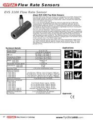
REPAIR<br />
BACKHOES<br />
VALVE HOUSING INSTALLATION<br />
CAUTION<br />
A B C D E F G<br />
Valve housing weighs approximately 27 kg (60<br />
lb); installation may require hoist or more than<br />
one person.<br />
H<br />
I<br />
J<br />
K<br />
L<br />
M<br />
N<br />
M94990<br />
MODEL 47<br />
M94880<br />
Port A (upper)<br />
Port B (lower)<br />
A—Bucket (Rod End) H—Bucket (Head End)<br />
B—Dipperstick (Head End) I—Dipperstick (Rod End)<br />
C—RH Stabilizer (Head End) J—RH Stabilizer (Rod End)<br />
D—LH Stabilizer (Head End) K—LH Stabilizer (Rod End)<br />
E—Boom (Rod End) L—Boom (Head End)<br />
F—Swing*<br />
M—Swing<br />
G—Outlet<br />
N—Inlet<br />
*Model 47—RH Swing Cylinder (Base End)<br />
*Model 48—LH Swing Control (Rod End)<br />
4. Install inlet, outlet, and cylinder hoses to the<br />
appropriate connectors.<br />
5. Install valve cover.<br />
6. Install rear shroud.<br />
7. Make operational checks. Note any leaking<br />
connections and tighten.<br />
MODEL 48<br />
M94881<br />
1. Attach valve housing at attaching points.<br />
2. Connect RH and LH joystick linkages with<br />
hardware.<br />
3. Connect RH and LH stabilizer control rods using<br />
pins, washers, and cotter pins.<br />
CYLINDER REMOVAL AND<br />
INSTALLATION<br />
BOOM CYLINDER<br />
Removal:<br />
1. Position tractor with enough clearance to<br />
completely extend the boom, dipperstick and<br />
bucket.<br />
2. Lower stabilizers with light pressure on the ground.<br />
3-22 6/22/99