LT3-00032-2-A - DDKS Industries, hydraulic components distributor
LT3-00032-2-A - DDKS Industries, hydraulic components distributor
LT3-00032-2-A - DDKS Industries, hydraulic components distributor
You also want an ePaper? Increase the reach of your titles
YUMPU automatically turns print PDFs into web optimized ePapers that Google loves.
ASSEMBLY PROCEDURE<br />
ROCKER CAM ASSEMBLY<br />
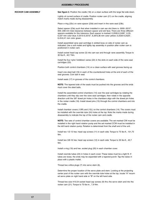
See figure 2. Position the cradle (18) on a clean surface with the large flat side down.<br />
Lightly oil curved surface of cradle. Position rocker cam (21) on the cradle, aligning<br />
match marks made during disassembly.<br />
Place o-ring (23c) on vane spacer (23d) and insert in the vane seal (23b).<br />
Select spacer (23e) such that when installed in cam ear slot there is .0000-.0015”,<br />
000-,038 mm total clearance between spacer and slot face. There are three different<br />
spacers available for this tolerance. Each spacer is marked: 0.2500-0.2495”, 6.35-<br />
6,337 mm color blue; 0.2515-0.2510”, 6,39-6,36 mm color yellow; 0.2530-0.2525”,<br />
6,43-6,41 mm color green.<br />
Install assembled vane seal cartridge in slotted boss on side of rocker cam as<br />
indicated. Use a soft mallet and lightly tap assembly in position after rocker cam is<br />
positioned in rocker cam.<br />
Install socket head cap screw (3) into cam ear and through vane assembly. Torque to<br />
30 lbs-ft., 40,7 Nm.<br />
Install the four nylon holddown vanes (22) in the slots on each side of the vane seal<br />
cartridges (23).<br />
Position both control chambers (14) on a clean surface with seal grooves facing up.<br />
Insert one steel ball (16) in each of the counterbored holes at the end of each of the<br />
seal grooves. Coin ball in seat.<br />
Install seals (17) in grooves of the control chambers.<br />
NOTE: The tapered side of the seals must be pushed into the grooves and the ends<br />
must cover the steel balls.<br />
Install the assembled control chambers (14) over the seal cartridges by rotating the<br />
chambers until they slip over the vane seal cartridges, then rotate in the opposite<br />
direction until the 3/8” dowel pin holes in the chambers align with the dowel pin holes<br />
in the rocker cradle (18). Install dowel pins (15) through the control chambers and into<br />
the cradle.<br />
Install chamber covers (13R) and (13L) on the control chambers (14). The covers must<br />
be installed with the override tube (24) holes at the top. Note the marks made during<br />
disassembly to indicate the top of the rocker cam and cradle.<br />
NOTE: Two sets of control chamber covers are available. The set marked CW must be<br />
installed in the right hand rotation pump and the set marked CCW must be installed in<br />
the left hand rotation pump. Rotation is determined from the shaft end of the unit.<br />
Install two 1/2-13 hex. head cap screws (11) in each side. Torque to 75 lbs-ft., 101,75<br />
Nm.<br />
Install two 3/8-16 hex. head cap screws (12) in each side. Torque to 30 lbs-ft., 40,7<br />
Nm.<br />
Install o-ring (19) and hex. socket plug (20) in each chamber cover.<br />
Install override tubes (24) in holes in each cover. These tubes must be a tight fit. If<br />
tubes are loose, the ends may be expanded with a tapered punch. Tap the tubes in<br />
place with a plastic mallet.<br />
Thread two orifice plugs (7) into servo stem (6).<br />
Determine the proper location of the servo plate and stem. Looking at the projecting<br />
center post of the rocker cam with the override tube holes at the top, locate “A” mounted<br />
servo plate on right hand side or “B” on the left hand side.<br />
Thread two size #10-24 socket head cap screws (9) thru the servo stem and into the<br />
rocker cam (21). Torque to 70 lbs-in., 7,9 Nm.<br />
17


