

LT3-00032-2-A - DDKS Industries, hydraulic components distributor
LT3-00032-2-A - DDKS Industries, hydraulic components distributor
LT3-00032-2-A - DDKS Industries, hydraulic components distributor

You also want an ePaper? Increase the reach of your titles
YUMPU automatically turns print PDFs into web optimized ePapers that Google loves.
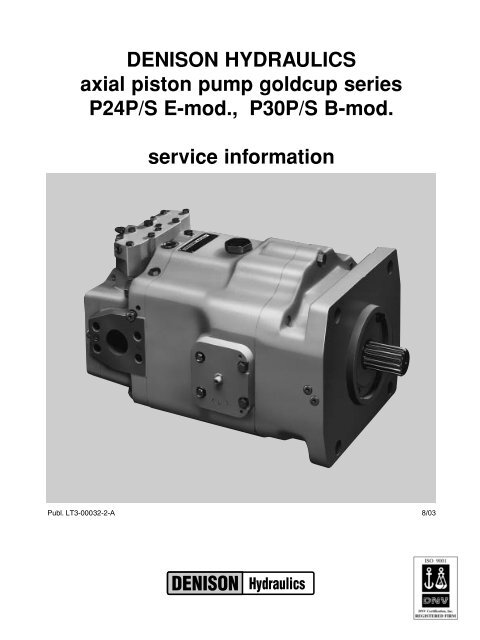
DENISON HYDRAULICS<br />
axial piston pump goldcup series<br />
P24P/S E-mod., P30P/S B-mod.<br />
service information<br />
Publ. <strong>LT3</strong>-<strong>00032</strong>-2-A 8/03
The product information, specifications, and descriptions contained in this publication have been<br />
compiled for the use and convenience of our customers from information furnished by the manufacturer;<br />
and we can not, and do not, accept any responsibility for the accuracy or correctness<br />
of any description, calculation, specification, or information contained herein. No such description,<br />
calculation, specification, or information regarding the products being sold has been made<br />
part of the basis of the bargain, nor has same created or amounted to an express warranty that<br />
the products would conform thereto. We are selling the goods and merchandise illustrated<br />
and described on this publication on an "as is" basis, and disclaim any implied warranty,<br />
including any warranty of merchantability or warranty of fitness for any particular purpose<br />
whatsoever, with respect to the goods and merchandise sold. All manufacturer warranties<br />
shall be passed on to our customers, but we shall not be responsible for special, indirect, incidental,<br />
or consequential damages resulting from the use of any of the products or information<br />
contained or described on this publication. Further, we reserve the right to revise or otherwise<br />
make product improvements at any time without notification.
CONTENTS<br />
PAGE<br />
technical characteristics 3<br />
fluid connections 4<br />
seal kits 4<br />
introduction 5<br />
description 5<br />
mounting 5<br />
rear pump mounting 5<br />
shaft information 5<br />
piping 5<br />
recommended fluids 6<br />
viscosity 6<br />
viscosity index 6<br />
temperature 6<br />
alternate fluids 6<br />
fluid cleanliness 6<br />
comparison of solid contamination classification system 6<br />
filling case 7<br />
service information 7<br />
maintenance 7<br />
start up procedures for new installations 7<br />
trouble shooting 8<br />
assembly tool drawings T1,T2,T3, and T4 10<br />
disassembly procedures 11<br />
rework limits of wear parts 13<br />
assembly procedures 15<br />
figure 1 shaft and bearing assembly 15<br />
figure 2 rocker cam, piston-shoes & retainer 15<br />
cam and cradle assemblies 16<br />
rocker cam 17<br />
piston and shoe 18<br />
figure 3 mounting flange, cam & cradle, barrel & auxiliary shaft 18<br />
figure 4 barrel and auxiliary drive shaft 24 series 19<br />
figure 4.1 barrel and auxiliary drive shaft 30 series 20<br />
figure 5 housing 20<br />
figure 6 housing, end cap cam and barrel 21<br />
mechanical shaft seal 21<br />
figure 7 seal assembly 22<br />
counter balance plate 23<br />
servo plate 23<br />
control cover 23<br />
figure 8 port block 24<br />
port block installation 24<br />
figure 9 barrel holddown and auxiliary pump 24 series 25<br />
barrel holddown and auxiliary pump 30 series 26<br />
auxiliary pump and end cover 26<br />
figure 10 rear drive adapter and shuttle valve 27<br />
rear drive adapter 28<br />
pilot valve 28<br />
shuttle valve 28<br />
figure 11 exploded view of shuttle valve and pilot valve ext. drain 29<br />
shuttle valve adapter 30<br />
shuttle valve mounting 30<br />
valve block assembly 30<br />
figure 12 valve block assembly 32<br />
valve block for servo valve 33<br />
figure 13 valve block for servo valve 36<br />
test procedure 37<br />
alternate test procedure 38<br />
control test - refer to control service manual S1-AM030 39<br />
<strong>hydraulic</strong> circuit P24/30P 41<br />
<strong>hydraulic</strong> circuit P24/30S 42<br />
installation drawings 43-61<br />
ordering code 62<br />
conversions & formulas 65<br />
2
TECHNICAL CHARACTERISTICS<br />
TECHNICAL<br />
CHARACTERISTICS<br />
specification term Goldcup 24 Goldcup 30<br />
•displacement at max. angle in 3 /rev. 24.6 30.6<br />
cm 3 /rev. 403 501,4<br />
•pressure, continuous psi 5000 5000<br />
bar 345 345<br />
•speed max. continuous at full stroke rpm 2100 1) 1800<br />
consult DENISON HYDRAULICS for higher speeds<br />
•flow, ports A or B at 1500 rpm gpm 159.7 198.7<br />
theo. at max. displ. Lpm 604,6 752,1<br />
at 1800 rpm gpm 191.7 238.4<br />
Lpm 725,5 902,5<br />
at 2100 rpm gpm 223.6 -<br />
Lpm 846 -<br />
P24P<br />
P30P<br />
•aux. pump theor. displ. / rev. 2) in 3 /rev 2.81 2.81<br />
cc/rev 46,1 46,1<br />
P24S 3) P30S 3)<br />
in 3 /rev 1.05 1.05<br />
cc/rev 17,2 17,2<br />
P24P<br />
P30P<br />
•flow, auxiliary pump at 1500 rpm gpm 18.2 18.2<br />
internal - theo. flow<br />
at 1800 rpm<br />
Lpm<br />
gpm<br />
69,1<br />
21.9<br />
69,1<br />
21.9<br />
Lpm 82,9 82,9<br />
at 2100 rpm gpm 25.5 -<br />
Lpm 96,7 -<br />
P24S 3) P30S 3)<br />
at 1500 rpm gpm 6.5 6.5<br />
Lpm 24,5 24,5<br />
at 1800 rpm gpm 7.8 7.8<br />
Lpm 29,5 29,5<br />
P24S 3) P30S 3)<br />
•flow, auxiliary pump at 1500 rpm 4) gpm 18.2 18.2<br />
external - standard T6C-025 Lpm 69,1 69,1<br />
at 1800 rpm gpm 21.9 21.9<br />
Lpm 82,9 82,9<br />
P24P P24S P30P P30S<br />
•aux. pump servo pressure range psi 340-640 490-790 360-772 490-902<br />
varies upward with pressure in bar 23-44 34-54 25-53 34-62<br />
port A or B,<br />
based on 0 psi 0 bar case pressure<br />
P24P P24S P30P P30S<br />
•Aux. pump replenishing pressure psi 180-220 330-370 180-220 330-370<br />
based on 0 psi 0 bar case pressure bar 12-15 23-26 12-15 23-26<br />
•mounting SAE 177-4 177-4<br />
(“F” 4- bolt) (“F” 4- bolt)<br />
•shaft-spline or keyed SAE 50-1,4 50-1,4<br />
(“F”)<br />
(“F”)<br />
•weight P24P P24S P30P P30S<br />
lbs 690 755 710 787<br />
kg 313 342 322 357<br />
1)<br />
On R & O oils rust and oxidation inhibitor.<br />
2)<br />
Standard, other sizes available.<br />
3)<br />
Internal cartridge provides servo flow and must be supercharged from external<br />
replenishing flow. from external auxiliary pump<br />
4)<br />
Any SAE 82-2 or SAE 101-2 mounting pump may be used, with the corresponding<br />
adapters.<br />
3
SEAL KITS<br />
FLUID CONNECTIONS<br />
Refer to page 40 for specifications<br />
SEAL KITS<br />
seal kit, P24/30 complete (includes control seals)<br />
valve block seal kit (all)<br />
shaft seal kit<br />
shaft seal<br />
controls seal kit (all – input & output)<br />
see chart below<br />
S23-17338-⊕Κ<br />
see chart below<br />
623-00015-5K<br />
S23-17000-⊕Κ<br />
Seal Kits for P24-30 Gold Cup Pumps<br />
CIPR MOD. SERIES SHAFT<br />
TYPE<br />
ROT.<br />
COMPLETE<br />
SEAL KIT<br />
SHUTTLE<br />
SHAFT SEAL KIT<br />
24,30 E & B<br />
24,30 E & B<br />
P<br />
S23-18006-⊕ K<br />
R<br />
2,3 R & L<br />
S23-18016-⊕ K<br />
S23-11516-⊕ K<br />
X<br />
S23-11514-⊕ K<br />
P 7,8 R S23-17038-⊕ K S23-16332-⊕ K<br />
N/A<br />
P 7,8 L S23-17039-⊕ K S23-16333-⊕ K<br />
R 7,8 R S23-18017-⊕ K S23-16332-⊕ K<br />
R 7,8 L S23-18018-⊕ K S23-16333-⊕ K<br />
X 7,8 R S23-18022-⊕ K S23-16332-⊕ K<br />
X 7,8 L S23-18023-⊕ K<br />
S23-16333-⊕ K<br />
S<br />
S23-17040-⊕ K<br />
2,3 R & L<br />
L<br />
S23-18019-⊕ K<br />
S23-11516-⊕ K<br />
S 7,8 R S23-17041-⊕ K<br />
S23-15089-⊕ K<br />
S23-16332-⊕ K<br />
S 7,8 L S23-17042-⊕ K S23-16333-⊕ K<br />
L 7,8 R S23-18020-⊕ K S23-16332-⊕ K<br />
L 7,8 L S23-18021-⊕ K<br />
S23-16333-⊕ K<br />
Seal Kits for P24-30 Gold Cup Pumps with T6C Auxiliary Pumps<br />
CIPR MOD. SERIES SHAFT<br />
TYPE<br />
ROT.<br />
COMPLETE<br />
SEAL KIT<br />
SHUTTLE<br />
SHAFT SEAL KIT<br />
24,30 E & B S<br />
2,3 R & L S23-11600-⊕ K S23-11516-⊕ K<br />
S23-15089-⊕ K<br />
7,8 R S23-15696-⊕ K S23-16332-⊕ K<br />
7,8 L S23-15697-⊕ K<br />
S23-16333-⊕ K<br />
Notes: Add –0 FOR BUNA, –4 for EPR Rubber or –5 for VITON in place of ⊕ .<br />
4
INSTALLATION<br />
INTRODUCTION<br />
DESCRIPTION<br />
MOUNTING<br />
REAR PUMP MOUNTING<br />
SHAFT INFORMATION<br />
PIPING<br />
The DENISON HYDRAULICS Goldcup 24 and 30 axial piston pumps feature advance<br />
design concepts which are time proven and provide for advanced pumping and control<br />
concepts. The instructions contained in this manual cover complete disassembly and<br />
re-assembly of the unit. Before proceeding with the disassembly or reassembly of any<br />
unit, this manual should be studied in ordered to become familiar with proper order<br />
and parts nomenclature.<br />
The use of a rocker cam to control the pump displacement provides a small package<br />
size, reduces wear, and speeds control response. The control vane actuator eliminates<br />
linkage and backlash inherent in typical stroking cylinder designs.<br />
Standard controls for the Goldcup units are rotary servo and compensator over-ride.<br />
Additional optional controls are also available.<br />
This pump is designed to operate in any position. The mounting hub and 4 bolt mounting<br />
flange are in full conformance with SAE standard. The pump shaft must be in alignment<br />
with the shaft of the prime mover and should be checked with a dial indicator.<br />
The mounting pad or adapter into which the fluid pump pilots must be concentric with<br />
the pump shaft to prevent bearing failure. This concentricity is particularly important if<br />
the shaft is rigidly connected to the prime mover without a flexible coupling.<br />
Caution: P24/30S Only<br />
Shaft seal on coupling shaft isolates internal replenishing pressure from the external<br />
pump. An axial load in pounds equal to 1.23 x replenishing pressure, psi, or Newtons<br />
equal to 79,3 x replenishing pressure bar, will be exerted on the shaft of the rear<br />
mounted pump. Shaft bearing capacity of the external pump must be considered<br />
when applying external pump.<br />
In any application it is advisable to check the alignment of the pump shaft to the prime<br />
mover to avoid side loading the pump shaft bearing and bending of the shaft.<br />
The maximum allowable offset of the pump shaft and prime mover is 0.006 inch, 0,15<br />
mm T.I.R. (Total indicator reading).<br />
The maximum allowable angular misalignment is ±.002 inch per inch radius, 0,002 mm<br />
per mm radius.<br />
Splined: The coupling interface must be lubricated. DENISON HYDRAULICS recommends<br />
lithium-molybdenum disulfide or similar grease. The female coupling should be<br />
hardened to 27-45 Rc and must conform to SAE-J498B(1971) class 1 flat root side fit.<br />
Keyed: High strength heat treated keys must be used. Replacement keys must be<br />
hardened to 27-34 Rc. The key corners must be chamfered 0.030”-0.040”, 0,75-1mm<br />
at 45 0 to clear radii that exist in the keyway.<br />
Note: Do not impact coupling to force it onto the shaft. A threaded hole, size M16 is<br />
provided in the end of the shaft.<br />
Both types of shafts will accept a side load of 1000 lbs., 454 kg at the center of the<br />
spline or key, with a B10 life of 9880 hours at 1800 rpm or 11856 hours at 1500 rpm.<br />
Connect inlet and outlet lines to the port block of the pump.<br />
The maximum case pressure is 75 psi, 5,7 bar continuous, 125 psi, 8,6 bar intermittent.<br />
When connecting case drain line make certain that drain plumbing passes above<br />
highest point of the pump before passing to the reservoir. If not, install a 5 psi, 0,3 bar<br />
case pressure check valve to be certain the case is filled with oil at all times.<br />
Note: High case pressure will result in reduced shaft bearing B10 life.<br />
The case leakage line must be of sufficient size to prevent back pressure in excess of<br />
75 psi, 5,7 bar and returned to the reservoir below the surface of the oil as far from the<br />
supply as possible. All fluid lines, whether pipe, tubing, or hose must be adequate size<br />
to assure free flow through the pump. We recommend 20 ft., 6,09 m max. per second<br />
for main flow and 4 ft., 1,4 m max. limit per second for suction lines. The case drain<br />
flow can exceed the steady state repl. pump flow during transient. Size the hose for<br />
10 ft., 3,05 m, max. per second. Pressure rating of piping hose must be adequate for<br />
service duty required. An undersize inlet line will prevent the pump from operating at<br />
full rated speed. An undersized outlet line will create back pressure and cause heat<br />
generation and improper operation. Flexible hose lines are recommended to connect<br />
the pump to system piping. If rigid piping is used, the workmanship must be accurate<br />
to eliminate strain on the pump port block or to the fluid connections.<br />
Sharp bends in the lines must be eliminated wherever possible. All system piping must<br />
be cleaned with solvent or equivalent before installing pump. Make sure the entire<br />
<strong>hydraulic</strong> system is free of dirt, lint, scale, or other foreign material. Flushing with a<br />
large temporary high pressure loop filter is recommended. Piping must be cleaned so<br />
that the fluid cleanliness specified below is maintained.<br />
Caution: Do not use galvanized pipe. Galvanized coating can flake off with continued<br />
use.<br />
5
INSTALLATION<br />
RECOMMENDED FLUIDS<br />
VISCOSITY<br />
VISCOSITY INDEX<br />
TEMPERATURE<br />
ALTERNATE FLUIDS<br />
The fluid recommended for use in these pumps has a petroleum base and contains<br />
agents which provide oxidation inhibition and anti-rust, anti-foam and de-aerating<br />
properties as described in DENISON HYDRAULICS standard HF-1. Where anti-wear<br />
additive fluids are specified, see DENISON HYDRAULICS standard HF-0.<br />
Max. at cold start - 7500 SUS, 1600 Cst<br />
(at low pressure, low flow, and if possible, low speed)<br />
Max. at full power - 750 SUS, 160 Cst<br />
Optimum for max. life - 140 SUS, 30 Cst<br />
Minimum at full power - 60 SUS, 10 Cst<br />
90 V.I. minimum. Higher values extend the range of operating temperature but may<br />
reduce the service life of the fluid.<br />
Determine by the viscosity characteristics of the fluid used. Because high temperatures<br />
degrade seals, reduce the service life of the fluid and create hazards, fluid<br />
temperatures should not exceed 180 0 F, 82 0 C at the case drain.<br />
Some applications require fire-resistant fluids. They will give good service if the system<br />
is originally designed for their use. Permissible fire resistant fluids include:<br />
Type<br />
Water-in-oil invert emulsions<br />
Water glycol solutions<br />
Phosphate esters<br />
DENISON HYDRAULICS Standard<br />
HF-3<br />
HF-4<br />
HF-5<br />
Consult DENISON HYDRAULICS for design requirements and warranty limitations for<br />
service with this class of fluids.<br />
See DENISON HYDRAULICS bulletin SP0-AM305 for more information.<br />
FLUID CLEANLINESS<br />
Fluid must be cleaned before and continuously during operation, by filters that maintain<br />
a cleanliness level of NAS 1638 class 8 (class 9 for 15 micron and smaller). This<br />
approximately corresponds to ISO 17/14. This fluid level cleanliness can usually be<br />
accomplished by the effective use of 10 micron filters. Better cleanliness levels will<br />
significantly extend the life of the <strong>components</strong>. As contaminant generation may vary<br />
with each application, each must be analyzed to determine proper filtration to maintain<br />
the required cleanliness level.<br />
COMPARISON OF SOLID CONTAMINATION CLASSIFICATION SYSTEM<br />
NATIONAL AERONAUTICS STANDARD (NAS) 1638<br />
class<br />
00 0 1 2 3 4 5 6 7 8 9 10 11 12<br />
5-15mm 125 250 500 1000 2000 4000 8000 16000 32000 64000 128000 256000 512000 1024000<br />
particle 15-25mm 22 44 89 178 356 712 1425 2850 5700 11400 22800 45600 91200 182400<br />
size 25-50mm 4 8 16 32 63 126 253 506 1012 2025 4050 8100 16200 32400<br />
range 50-100mm 1 2 3 6 11 22 45 90 180 360 720 1440 2880 5760<br />
>100mm 0 0 1 1 2 4 8 16 32 64 128 256 512 1024<br />
maximum >5mm 152 304 609 1217 2432 4864 9731 19462 38924 77849 155698 311396 622792 1245584<br />
particles >15mm 27 54 109 217 432 864 1731 3462 6924 13849 27698 55396 110792 221584<br />
ISO:DIS 4406; SAE J1165<br />
iso solid contaminant code<br />
8/5 9/6 10/7 11/8 12/9 13/10 14/11 15/12 16/13 17/14 18/15 19/16 20/17 21/18 22/19<br />
maximum >5mm 250 500 1000 2000 4000 8000 16000 32000 64000 130000 250000 500000 1000000 2000000 4000000<br />
particles >15mm 32 64 130 250 500 1000 2000 4000 8000 16000 32000 64000 130000 250000 500000<br />
NOTES: All measurements are for a 100 ml sample size.<br />
6
INSTALLATION<br />
FILLING CASE<br />
It is essential to make certain that the case (pump housing) is as full of fluid as possible<br />
and remains full during operation and at rest.<br />
Always fill to the highest available point. Remove a plug or screw and allow the oil to<br />
escape through this point.<br />
Recommended fill points:<br />
Mounting orientation vertical, shaft up. D1 or D2 (drain) port in housing.<br />
Vent DG2 port in mounting flange (new units) or<br />
one of the upper screws which attach the control.<br />
See installation drawing.<br />
Vertical, shaft down 1) or horizontal<br />
drain ports to the side.<br />
D1 or D2 (drain) port in housing.<br />
1) Vent DG (case gage) port in port block.<br />
SERVICE INFORMATION<br />
MAINTENANCE<br />
START UP PROCEDURES FOR<br />
NEW INSTALLATIONS<br />
These <strong>hydraulic</strong> products are designed to give long dependable service when properly<br />
applied and their systems properly maintained. These general instructions apply to typical<br />
systems. Specific instructions for particular equipment can be developed from<br />
them.<br />
This pump is self-lubricating and preventative maintenance is limited to keeping system<br />
fluid clean by changing filters frequently. Keep all fittings and screws tight. Do not<br />
operate at pressures and speeds in excess of the recommended limit. If the pump<br />
does not operate properly, check the troubleshooting chart before attempting to overhaul<br />
the unit. Overhauling may be accomplished by referring to the disassembly,<br />
rework limits of wear parts, and assembly procedures.<br />
•Read and understand the instruction manual. Identify <strong>components</strong> and their function.<br />
•Visually inspect <strong>components</strong> and lines for possible damage.<br />
•Check reservoir for cleanliness and drain and clean as required.<br />
•Check fluid level and fill as required with filtered fluid at least as clean as that recom<br />
mended. Fill pump case with clean oil prior to starting.<br />
•Check alignment of drive.<br />
•Check oil cooler and activate it, if included in circuit.<br />
•Reduce pressure settings of relief valve or compensator. Make sure accurate pressure<br />
readings can be made at appropriate places.<br />
•If solenoids are included in system, check for actuation.<br />
•Start pump drive first by jogging prime mover. Make sure pump and motor fill properly.<br />
Caution: Ensure that the servo/replenish pump primes at startup. This is important on a<br />
newly installed application or one that allows the servo/replenish pump to lose its<br />
prime during shutdown. Failure to adequately prime can damage the main pump or the<br />
servo/replenish pump.<br />
•Bleed system of air. Re-check fluid level.<br />
•Cycle unloaded machine at low pressure and observe actuation (at low speed, if<br />
possible).<br />
•Increase pressure settings gradually in steps. Check for leaks in all lines, especially<br />
pump and motor inlet lines.<br />
•Make correct pressure adjustments.<br />
•Gradually increase speed. Be alert for trouble as indicated by changes in sounds, system<br />
shocks and air in fluid.<br />
•Equipment is operational.<br />
7
TROUBLE SHOOTING<br />
TROUBLESHOOTING<br />
Component problems and circuit problems are often interrelated. An improper circuit<br />
may operate with apparent success but will cause failure of a particular component<br />
within it. The component failure is the effect, not the cause of the problem.<br />
This general guide is offered to help in locating and eliminating the cause of the<br />
problems by studying their effects.<br />
effect of trouble possible cause fault which needs remedy<br />
noisy pump air in fluid leak in suction line<br />
low fluid level<br />
turbulent fluid<br />
return lines above fluid level<br />
gas leak from accumulator<br />
excessive pressure drop in the inlet line from<br />
a pressurized reservoir<br />
suction line strainer acting as air trap<br />
cavitation in fluid too cold<br />
pump or motor fluid too viscous<br />
rotating group<br />
misaligned shaft<br />
mechanical fault<br />
in pump<br />
fluid too heavy<br />
shaft speed too high<br />
suction line too small<br />
suction line collapsed<br />
suction strainer too small or too fine<br />
suction strainer too dirty<br />
operating altitude too high<br />
boost or replenishment pressure too low<br />
replenishment flow too small for dynamic<br />
conditions<br />
faulty installation<br />
distortion in mounting<br />
axial interference<br />
faulty coupling<br />
excessive overhung loads<br />
piston and shoe looseness or failure<br />
bearing failure<br />
incorrect port plate selection or index<br />
eroded or worn parts in the displacement control<br />
erosion on barrel air in fluid see above<br />
ports and port cavitation see above<br />
plate<br />
high wear in excessive loads reduce pressure settings<br />
pump & motor<br />
contaminant<br />
particles in fluid<br />
improper fluid<br />
improper repair<br />
unwanted water<br />
in fluid<br />
reduce speed<br />
improper filter maintenance<br />
filters too coarse<br />
introduction of dirty fluid to system<br />
reservoir openings<br />
improper reservoir breather<br />
improper line replacement<br />
fluid too thin or thick for operating temperatures<br />
range<br />
breakdown of fluid with time/temperature/shearing<br />
effects<br />
incorrect additives in new fluid<br />
destruction of additive effectiveness with chemical<br />
aging<br />
incorrect parts<br />
incorrect procedures, dimensions, finishes<br />
condensation<br />
faulty breather/strainer<br />
heat exchanger leakage<br />
faulty clean-up practice<br />
water in make-up fluid<br />
8
TROUBLESHOOTING<br />
TROUBLESHOOTING<br />
(continued)<br />
effect of trouble possible cause fault which needs remedy<br />
pressure shocks cogging load mechanical considerations<br />
worn relief valve needed repairs<br />
worn compen- needed repairs<br />
sator<br />
slow response in replace or relocate<br />
check valves<br />
servo pressure increase pressure and check pressure drop<br />
too low to through servo filter<br />
maintain firm<br />
control<br />
excessive de- improve decompression control<br />
compression<br />
energy rates<br />
excessive line reduce line size or lengths<br />
capacitance eliminate hose<br />
(line volume,<br />
line stretch,<br />
accumulator<br />
effects)<br />
barrel blow-off re-check pump hold-down, rotating group, drain<br />
pressure<br />
heating of fluid excessive pump re-check case drain flow and repair as required<br />
or motor leak- fluid too thin<br />
age<br />
improper assembly, port timing<br />
relief valve set too low(compared to load or to compensator)<br />
instability caused by back pressure, worn parts<br />
compensator set too high (compared to relief)<br />
worn parts<br />
pump too large<br />
for fluid needs<br />
heat exchanger<br />
reservoir<br />
select smaller pump displacement<br />
water turned off or too little flow<br />
water too hot<br />
fan clogged or restricted<br />
efficiency reduced by mud or scale deposits<br />
intermittent <strong>hydraulic</strong> fluid flow<br />
too little fluid<br />
entrained air in fluid<br />
improper baffles<br />
insulating air blanket that prevents heat rejection<br />
heat pickup from adjacent equipment<br />
9
ASSEMBLY / DISASSEMBLY TOOLS<br />
T1<br />
No longer used.<br />
T2<br />
Barrel H.D. adjustment tool<br />
T2 Material - cold roll steel<br />
T3<br />
Replenishing and servo pump removal tool<br />
T4<br />
Shaft seal installation tool - rear adapter<br />
10
UNIT DISASSEMBLY<br />
INTRODUCTION<br />
DISASSEMBLY<br />
The instructions contained in this section cover a complete teardown of the subject<br />
pump. Disassemble only as far as necessary to replace or repair any worn parts.<br />
CAUTION: On 24 series units relax barrel holddown prior to removal of shaft seal or<br />
main shaft. Failure to follow this procedure may result in pump failure.<br />
NOTE: The four main assembly bolts (1, Figure 9) are torqued to 450 lbs-ft., 610,2<br />
Nm. These bolts should be loosened prior to removing unit for disassembly.<br />
Position pump unit so that the valve block assembly (11/12, Figure 10) is on top.<br />
A bench or similar suitable surface capable of supporting unit should be used.<br />
Disassembly area should be clean.<br />
VALVE BLOCK<br />
See figure 10. Remove the eight hex. head cap screws (12) and lift the entire block<br />
assembly from the port block.<br />
See figure 13. Remove the four hex. head cap screws (58) and four soc. hd. screws<br />
(53) and lift the entire block assembly from the port block.<br />
(after 7-93)<br />
See figure 12. Remove plugs (20), (23) and pin (21). Remove the 8-32 nut from the<br />
bottom of block (1) to remove filter assembly (14). Do not remove the check valves (2).<br />
Remove housing (8), o-ring (9), piston seal (10), o-ring (11), screw (6), nut (7), and<br />
acorn nut (45) as a unit.<br />
Remove spring (12) and cone (13). Remove seat (5) and o-ring (4).<br />
NOTE: Seat is made for hex. wrenching. Use 1/2” six point socket with 1/4” drive.<br />
Remove plug (25) and replenishing relief valve (36).<br />
Remove o-rings (37), (48) and (47). Remove four screws (43) and remove the retainer<br />
plate (42). Do not remove roll pins (46) unless replacements are needed.<br />
Remove gasket (29) and seats (27) and (28). Remove poppets (30), (31) and springs<br />
(32), (33), (35) and retainer (34).<br />
Inspect orifices (3) visually to insure they are open. Do not remove unless damage or<br />
clogging is apparent.<br />
CONTROL COVERS<br />
See figure 7. Remove the four screws (13) with nyltite washers (12) from the side<br />
cover (15) and remove the input control assembly.<br />
NOTE: The nyltite washers must be replaced at assembly.<br />
Remove the four screws (13) with nyltite washers (12) from the side cover (14).<br />
Remove the two screws (11) and spacers (10) and remove the balance plate (9).<br />
See figure 6. Remove the two screws (6) and remove the balance stem (7).<br />
SERVO/REPLENISH PUMP<br />
AND BARREL HOLDDOWN<br />
NOTE: P24/30S units will require removing the shuttle valve assembly and external<br />
vane pump assembly and tubing.<br />
Removal of External Aux. Pump Shuttle Valve, Mounting Adapter and Internal<br />
Aux. Pump<br />
See figure 10. Remove tubing between external pump and main pump.<br />
Remove two screws holding pump. Remove pump from rear drive mounting pad.<br />
Remove four screws holding shuttle (19) in place. Remove shuttle block.<br />
Remove four screws (18) attaching shuttle adapter (17) and remove adapter and<br />
o-rings (15) & (16).<br />
Remove six screws (7) and mounting adapter (6), coupling (14), and gasket (22).<br />
On non-rear drive units. Remove plug (9) and o-ring (8).<br />
Remove eight screws (7), and end cover (6), two tetraseals (5) and o-rings (4) and (3).<br />
Remove auxiliary pump assembly (2).<br />
11
UNIT DISASSEMBLY<br />
SERVO/REPLENISH PUMP<br />
AND BARREL HOLDDOWN<br />
(continued)<br />
(24 series barrel holddown)<br />
NOTE: This is a complete vane cartridge assembly and removed in one step. A puller<br />
tool T3 is recommended.<br />
Remove sealing washer (1).<br />
See figure 4. Remove holddown lock retainer ring (8). (Use internal snap ring pliers.)<br />
See figure 9. Remove four screws (1) and two screws (8). NOTE: There is a preload<br />
from the barrel holddown which will lift the port block approximately 1/8” (3.2mm) at<br />
release.<br />
Carefully lift and remove port block (2) and port plate (4). CAUTION: The port plate<br />
may cling to the barrel face because of oil film. Do not allow the port plate to fall and<br />
become damaged.<br />
See figure 6. Remove the face plate (2) and face plate pins (1) from the face of the<br />
barrel assembly.<br />
See figure 4. Remove holddown adjusting screw lock (7), use an 18” blade type<br />
screwdriver, with the blade ground down to clear holddown shaft.<br />
See figure 7. Lock main shaft from turning.<br />
See figure 4. Use special tool T2, slip over auxiliary shaft (2) and engage dowels into<br />
holddown adjusting screw (6). Loosen load but do not remove.<br />
See figure 6. Remove two bolts (5) holding housing and flange together.<br />
See figure 3. Push tubes (4) out of housing slots and toward barrel, do not bend or<br />
damage them.<br />
See figure 6. Lift housing (4) over tubes and barrel assembly and remove. Mounting<br />
flange must be driven from housing due to tight fit.<br />
NOTE: Do not damage gasket faces in this process. Do not remove the retaining<br />
screws or bearing from the housing unless bearing is damaged and replacement is<br />
necessary.<br />
Barrel assembly can be removed by lifting with auxiliary shaft. The pistons will remain<br />
with the cam assembly. These parts are precision finished and must be handled with<br />
extreme care!<br />
See figure 4. Using special tool T2, holddown assembly can be removed from barrel.<br />
Remove adjusting screw, (6), spring (5), retainer (4), spherical seat (3) and auxiliary<br />
shaft (2).<br />
(30 series barrel holddown)<br />
See figure 9. Remove four screws (1) and two screws (8). NOTE: There is a preload<br />
from the barrel holddown which will lift the port block approximately 1/8” (3.2mm) at<br />
release.<br />
Carefully lift and remove port block (2) and port plate (4).<br />
CAUTION: The port plate may cling to the barrel face because of oil film. Do not allow<br />
the port plate to fall and become damaged.<br />
See figure 6. Remove the face plate (2) and face plate pins (1) from the face of the<br />
barrel assembly.<br />
See figure 4.1. Loosen six screws gradually in alternating sequence.<br />
CAUTION: Holddown is under preload. Do not remove screws completely.<br />
Insert three #10-32 screws into the three #10-32 threaded holes. Alternately turn in<br />
screws till the tapered retainer releases. A loud crack sound should be heard when it<br />
releases.<br />
See figure 7. Lock main shaft from turning.<br />
See figure 4.1. Use special tool T2, slip it over auxiliary shaft (2) and engage dowels<br />
into barrel holddown nut assy. (5). Loosen load but do not remove.<br />
See figure 6. Remove two bolts (5) holding housing and flange together.<br />
12
UNIT DISASSEMBLY<br />
(30 series barrel holddown<br />
continued)<br />
See figure 3. Push tubes (4) out of housing slots and toward barrel, do not bend or<br />
damage them.<br />
See figure 6. Lift housing (4) over tubes and barrel assembly and remove. Mounting<br />
flange must be driven from the housing due to tight fit.<br />
NOTE: Do not damage gasket faces in this process. Do not remove the retaining<br />
screws or bearing from the housing unless bearing is damaged and replacement is<br />
necessary.<br />
Barrel assembly can be removed by lifting with auxiliary shaft. The pistons will remain<br />
with the cam assembly. These parts are precision finished and must be handled with<br />
extreme care!<br />
PORT BLOCK<br />
See figure 8. Remove the check valve assemblies (7) from the port block.<br />
Remove plugs (9) and (10).<br />
Remove two screws (4), lockwashers (5), check rings (6) and clamps (3).<br />
DRIVE SHAFT<br />
See figure 7. NOTE: Pump cam must be on center 0° angle before removing shaft.<br />
Remove four screws (5), seal retainer (2), gaskets (4), and stationary part of shaft seal<br />
assembly (3). Refer to view of item (3).<br />
Remove the carbon ring and the remainder of the shaft seal from the shaft.<br />
Remove shaft and bearing assembly (1).<br />
ROCKER CAM AND CONTROL<br />
STROKING ASSEMBLY<br />
See figure 3. Remove pressure feed tubes (4) from the cradle. DO NOT BEND THESE<br />
LINES. Discard all bent lines.<br />
Remove the rocker cam assembly from the mounting flange by carefully tilting mounting<br />
flange on its side and using a 1/4-20 threaded rod as a puller, remove plugs (11)<br />
with o-rings (8), and then remove screws (9) attaching cradle to mounting flange.<br />
Position rocker cam assembly on a clean surface with the override tubes (2) in a<br />
horizontal position and located at the top.<br />
See figure 2. Mark the cam (21) and cradle (18) as indicated. These marks will<br />
determine positioning of parts during assembly.<br />
Position the assembly in an upright position on the flat surface of the cradle.<br />
Remove the retaining ring (1), thrust washer (2), piston and shoe assembly (4) and<br />
creep plate (5) from the rocker cam (21).<br />
Remove the four screws (11) and four screws (12) from the control chamber covers<br />
(13R) and (13L).<br />
Remove the control chambers (14). Remove the seals (17), four steel balls (16) and<br />
dowel pins (15).<br />
Remove the screw (3), vane seal cartridges (23), holddown vanes (22) from the rocker<br />
cam (21).<br />
Remove the rocker cam from the cradle (18).<br />
REWORK LIMITS OF WEAR<br />
PARTS<br />
wear part max. rework from min. dimension<br />
original dimension after rework<br />
port plate face 0.010”, 0.254 mm 0.735”, 18.67 mm<br />
shoe retainer face 0.005”, 0.127 mm 0.494”, 12.55 mm<br />
1)<br />
piston shoe face, pocket 0.010”, 0.254 mm 0.010”, 0.254 mm<br />
creep plate face 0.010”, 0.524 mm 0.365”, 9.27 mm<br />
face plate none replace<br />
1)<br />
No rework allowed on 30 in. 3 piston shoe face.<br />
13
UNIT DISASSEMBLY<br />
REWORK LIMITS OF WEAR<br />
PARTS<br />
(continued)<br />
IMPORTANT:<br />
The port plate finish must be 8 microinches, .0203 micrometer both faces, flat within<br />
0.00006”, 0,0015 mm and parallel within 0.001”, 0,0254 mm total indicator reading.<br />
The creep plate wear face finish must be 5 microinches, .0127 micrometer, flat within<br />
0.0005”, 0,0127 mm and parallel to the backside within 0.001”, 0,0254 mm total indicator<br />
reading.<br />
The shoe retainer wear face finish must be 32 microinches, .0813 micrometer and flat<br />
within 0.0005”, 0,0127 mm. Must not be convex.<br />
The piston shoes wear face finish must be 30 microinches, .0762 micrometer and must<br />
be lapped in a set with the retainer plate, all shoe sole thicknesses to be within 0.001”,<br />
0,0254 mm after lapping. The maximum permissible shoe and piston axial looseness is<br />
0.010”, 0,254 mm.<br />
The special retaining ring service kit S23-12629 may be required to control shoe<br />
holddown clearance.<br />
14
ASSEMBLY PROCEDURE<br />
CLEANING AND INSPECTION<br />
All parts must be inspected and be free of material defects, dirt, scratches or any<br />
foreign material.<br />
All parts must be cleaned with a suitable cleaning solvent and all holes and passages<br />
blown out with dry, clean, compressed air.<br />
After cleaning and inspection, all parts must be covered with a light film of oil and protected<br />
from dirt and moisture. Excessive handling of internal parts should be avoided<br />
prior to assembly.<br />
During assembly, lapped and ground surfaces must be lubricated with clean oil and<br />
protected from nicks or surface damage.<br />
DRIVE SHAFT AND BEARING<br />
ASSEMBLY<br />
See figure 1. Slide the bearing (2) over the short end of the shaft and seat against the<br />
shoulder. Support only the inner race of the bearing and press on the long end of the<br />
shaft, to install bearing.<br />
Do not use excessive force. Use extreme care passing the ring over the seal surface.<br />
Install the retaining ring (3) in the groove. Be sure that the ring is fully seated.<br />
2<br />
3<br />
1<br />
4<br />
#3 SHAFT #2 SHAFT<br />
PARTS LIST FOR FIGURE 1<br />
S23-12474 DRIVE SHAFT #3 ASSEMBLY SPLINED<br />
S23-12475 DRIVE SHAFT #2 ASSEMBLY KEYED<br />
quantity<br />
item description part no. #3 #2<br />
1 #3 spline shaft 033-91139 1 -<br />
#2 keyed shaft 033-91140 - 1<br />
2 shaft bearing 230-82213 1 1<br />
3 retaining ring 033-71712 1 1<br />
4 square key 033-71910 - 1<br />
FIGURE 1<br />
ROCKER CAM, PISTONS-SHOES &<br />
RETAINER<br />
FIGURE 2<br />
15
ASSEMBLY PROCEDURE<br />
CAM-CRADLE ASSEMBLIES<br />
items 6 through (less item 24) 25,<br />
figure 2<br />
ROCKER CAM, PISTONS-SHOES &<br />
RETAINER<br />
S23-12478 is for RH CW rotation pumps with “B” suffix input control on right side. 1)<br />
S23-12479 is for LH CCW rotation pumps with “B” suffix input control on right side. 1)<br />
S23-12476 is for RH CW rotation pumps with “A” suffix input control on left side. 1)<br />
S23-12477 is for LH CCW rotation pumps with “A” suffix input control on right side. 1)<br />
1)<br />
Viewed from shaft end of pump with valve block on top 12 o’clock position. 1)<br />
PARTS LIST FOR FIGURE 2<br />
item description part no. quantity<br />
1 retaining ring-use only one 1<br />
.089-.087”, 2,261-2,210mm thick with yellow dot 033-71716<br />
.087-.085”, 2,270-2,159mm thick with green dot 033-71717<br />
.085-.083”, 2,159-2,108mm thick with white dot 033-91130<br />
.083-.081”, 2,108-2,057mm thick with red dot 033-71718<br />
.081-.079”, 2,057-2,007mm thick with blue dot 033-59746<br />
retaining ring service kit S23-12629<br />
2 thrust washer 033-59805 1<br />
3 socket head cap screw 359-13160 2<br />
4 retainer-piston-shoe assy. P24 S13-44470 1<br />
retainer-piston-shoe assy. P30 S23-12684<br />
5 creep plate 033-91653 1<br />
6 servo stem 033-71773 1<br />
7 orifice screw 033-70819 2<br />
8 button head cap screw 353-25023 2<br />
9 socket head cap screw 358-10120 2<br />
10 servo plate 033-53874 1<br />
11 hex. head cap screw 1/2-13 306-40174 4<br />
12 hex. head cap screw 3/8-16 306-40035 4<br />
13R right side chamber cover CW 033-71598 1<br />
right side chamber cover CCW 033-71595 1<br />
13L left side chamber cover CW 033-71597 1<br />
left side chamber cover CCW 033-71593 1<br />
14 control chamber 033-71757 2<br />
15 dowel pin 324-22428 4<br />
16 steel ball 201-06001 4<br />
17 control chamber seal 606-25045 2<br />
18 rocker cradle 033-91141 1<br />
19 o-ring 691-00905 2<br />
20 hexagon socket plug 488-35020 2<br />
21 rocker cam S23-12482 1<br />
22 holddown vane 033-70816 4<br />
23 vane seal cartridge see below 2<br />
23a vane seal backup plate 033-71726 4<br />
23b vane seal 033-71714 2<br />
23c o-ring 691-00128 2<br />
23d vane spacer 033-71727 2<br />
23e spacer 2<br />
.2500-.2495”, 6,35-6,337 mm blue 033-59806<br />
.2515-.2510”, 6,39-6,36 mm yellow 033-59983<br />
.2530-.2525” 6,43-6,41 mm green 033-59984<br />
24 override tube P24 033-71731 2<br />
override tube P30 033-57933 2<br />
25 hex. socket set screw 312-09032 2<br />
16
ASSEMBLY PROCEDURE<br />
ROCKER CAM ASSEMBLY<br />
See figure 2. Position the cradle (18) on a clean surface with the large flat side down.<br />
Lightly oil curved surface of cradle. Position rocker cam (21) on the cradle, aligning<br />
match marks made during disassembly.<br />
Place o-ring (23c) on vane spacer (23d) and insert in the vane seal (23b).<br />
Select spacer (23e) such that when installed in cam ear slot there is .0000-.0015”,<br />
000-,038 mm total clearance between spacer and slot face. There are three different<br />
spacers available for this tolerance. Each spacer is marked: 0.2500-0.2495”, 6.35-<br />
6,337 mm color blue; 0.2515-0.2510”, 6,39-6,36 mm color yellow; 0.2530-0.2525”,<br />
6,43-6,41 mm color green.<br />
Install assembled vane seal cartridge in slotted boss on side of rocker cam as<br />
indicated. Use a soft mallet and lightly tap assembly in position after rocker cam is<br />
positioned in rocker cam.<br />
Install socket head cap screw (3) into cam ear and through vane assembly. Torque to<br />
30 lbs-ft., 40,7 Nm.<br />
Install the four nylon holddown vanes (22) in the slots on each side of the vane seal<br />
cartridges (23).<br />
Position both control chambers (14) on a clean surface with seal grooves facing up.<br />
Insert one steel ball (16) in each of the counterbored holes at the end of each of the<br />
seal grooves. Coin ball in seat.<br />
Install seals (17) in grooves of the control chambers.<br />
NOTE: The tapered side of the seals must be pushed into the grooves and the ends<br />
must cover the steel balls.<br />
Install the assembled control chambers (14) over the seal cartridges by rotating the<br />
chambers until they slip over the vane seal cartridges, then rotate in the opposite<br />
direction until the 3/8” dowel pin holes in the chambers align with the dowel pin holes<br />
in the rocker cradle (18). Install dowel pins (15) through the control chambers and into<br />
the cradle.<br />
Install chamber covers (13R) and (13L) on the control chambers (14). The covers must<br />
be installed with the override tube (24) holes at the top. Note the marks made during<br />
disassembly to indicate the top of the rocker cam and cradle.<br />
NOTE: Two sets of control chamber covers are available. The set marked CW must be<br />
installed in the right hand rotation pump and the set marked CCW must be installed in<br />
the left hand rotation pump. Rotation is determined from the shaft end of the unit.<br />
Install two 1/2-13 hex. head cap screws (11) in each side. Torque to 75 lbs-ft., 101,75<br />
Nm.<br />
Install two 3/8-16 hex. head cap screws (12) in each side. Torque to 30 lbs-ft., 40,7<br />
Nm.<br />
Install o-ring (19) and hex. socket plug (20) in each chamber cover.<br />
Install override tubes (24) in holes in each cover. These tubes must be a tight fit. If<br />
tubes are loose, the ends may be expanded with a tapered punch. Tap the tubes in<br />
place with a plastic mallet.<br />
Thread two orifice plugs (7) into servo stem (6).<br />
Determine the proper location of the servo plate and stem. Looking at the projecting<br />
center post of the rocker cam with the override tube holes at the top, locate “A” mounted<br />
servo plate on right hand side or “B” on the left hand side.<br />
Thread two size #10-24 socket head cap screws (9) thru the servo stem and into the<br />
rocker cam (21). Torque to 70 lbs-in., 7,9 Nm.<br />
17
ASSEMBLY PROCEDURE<br />
ROCKER CAM ASSEMBLY<br />
(continued)<br />
PISTON AND SHOE ASSEMBLY<br />
Install servo plate (10) to stem (6) with two #10-24 button head screws (8). Torque<br />
to 30 lbs-in., 3,4 Nm. Install two set screws (25) in servo plate. Torque to 25 lbs-in., 2,8<br />
Nm.<br />
NOTE: The balance plate cannot be assembled to the rocker cam until after the<br />
housing assembly installation has been completed See figure 7.<br />
Install creep plate (5) over center post on rocker (21).<br />
Insert piston and shoes into retainer and install entire assembly (4) against creep<br />
plate.<br />
Install thrust washer (2) over center post of cam and against shoe retainer. Grooved<br />
side of washer must face shoe retainer.<br />
Install the thickest retaining ring (1) that will fit in the groove on the rocker cam center<br />
post which will allow a maximum clearance of 0.002-0.005”, 0,05-0,13 mm between<br />
the creep plate and shoe faces. To check this clearance, grasp one piston and lift until<br />
tight against shoe retainer. Insert thickness gage. If this clearance is not correct, select<br />
the appropriate retaining ring and repeat the checking procedure.<br />
MOUNTING FLANGE,<br />
CAM & CRADLE, BARREL &<br />
AUXILIARY SHAFT ASSEMBLY<br />
NOTE: If metallic thickness gage is used, caution should be exercised not to scratch<br />
shoe face. There are five different retaining rings available for this tolerance. Each<br />
retaining ring is marked: 0.081-0.079”, 2,03-1,98 mm thick blue dot; 0.083-0.081”,<br />
2,08-2,05 mm thick red dot; 0.085-0.083”, 2,159-2,108 mm thick white dot; 0.087-<br />
0.085”, 2,18-2,16 mm thick green dot; and 0.089-0.087”, 2,4-2,21 mm thick yellow<br />
dot. The piston and shoe assembly must be free to rotate 360 0 by hand.<br />
See figure 3. Install two elbow fittings (3) into the threaded holes in the cradle.<br />
NOTE: Check the feed tubes (4) and override tubes (2) by fitting them into the correct<br />
port block holes before assembling to the stroking assembly (5). They must be a snug<br />
push fit as they rely on a metal to metal seal to contain system pressure. If they fit<br />
loose or are damaged they must be replaced.<br />
Install pressure feed tubes (4) to elbow fittings (3). Tighten the connectors until snug.<br />
Position the mounting flange (7) with the large open end facing up and install two<br />
dowel pins (6) in the cradle mounting surface and one 3/8”, 9,5mm diameter dowel pin<br />
(10) in the outer edge of the flange.<br />
Install the rocker cam and cradle assembly (5) over the dowel pins (6) in the mounting<br />
flange.<br />
NOTE: Pressure feed tubes to be on the same side of mounting flange centerline as<br />
the 3/8”, 9,5 mm diameter dowel pin (10).<br />
With cam and cradle installed, tilt mounting flange on its side and secure with two soc.<br />
hd. cap screws (9). Torque to 50 lbs-ft, 67,8 Nm.<br />
CASE<br />
OVERFILL<br />
PORT<br />
Insert plugs (11) with o-rings (8) into soc. hd. cap screw (9) c’bores. Be sure tapped<br />
hole in plug (11) is visible after installation. This is used for removal.<br />
Install plugs (12) with o-rings (13).<br />
AIR<br />
BLEED<br />
PORT<br />
13<br />
Install shaft assembly<br />
See figure 7. Install shaft and bearing assembly (1), either splined or keyed as specified<br />
by inserting shaft through bores, a few light taps are required on the outer race to<br />
completely engage and seat bearing.<br />
NOTE: Do not tap on end of shaft, but on the bearing outer race only.<br />
12<br />
13<br />
12<br />
Tapped hole<br />
this side.<br />
FIGURE 3<br />
18
MOUNTING FLANGE,<br />
CAM & CRADLE, BARREL &<br />
AUXILIARY SHAFT ASSEMBLY<br />
(continued)<br />
PARTS LIST FOR FIGURE 3<br />
item description part no. quantity<br />
1 barrel & aux. shaft assembly see fig.4 or 4.1 1<br />
2 override tubes item 24 see fig. 2 2<br />
3 male elbow 473-15041 2<br />
4 tube assembly P24 S13-44469 2<br />
tube assembly P30 S23-12172 2<br />
5 rocker cam & stroking assy. see fig. 2 1<br />
6 dowel pin 324-24028 2<br />
7 mounting flange 033-91137 1<br />
8 o-ring 671-00111 2<br />
9 soc. hd. cap screw 358-16260 2<br />
10 dowel pin 324-22416 1<br />
11 plug 033-57475 2<br />
12 plug 488-35061 3<br />
13 o-ring 691-00904 3<br />
Return the mounting flange to an upright position and tilt the rocker cam to either<br />
extreme attitude on the cradle.<br />
Position the barrel assembly (1) directly over the pistons. Starting with the uppermost<br />
piston, guide them one at time into the barrel bores.<br />
BARREL AND AUXILIARY<br />
DRIVE SHAFT 24 SERIES<br />
NOTE: Support the barrel on the main shaft but tilted slightly so as not to allow the<br />
barrel to drop and fully engage the barrel and shaft splines. Now the holddown assembly<br />
can be installed without any load against it.<br />
See figure 4. Install auxiliary shaft (2) large spline end first into counterbore in face of<br />
barrel spline.<br />
Install spherical seat (3) round or spherical face up into counterbore in face of barrel.<br />
Install spring retainer (4) socket side down into counterbore, install spring (5) and seat<br />
against spring retainer.<br />
Thread holddown adjusting screw (6) into counterbore approximately four threads.<br />
Tilt barrel vertically and engage main shaft spline with the barrel spline allowing barrel<br />
to drop in place.<br />
Thread holddown adjusting screw (6) into counterbore until it is flush to 0.060”, 1.52<br />
mm maximum below barrel face.<br />
FIGURE 4<br />
PARTS LIST FOR FIGURE 4 (P24)<br />
quantity<br />
item description part no. P24<br />
1 barrel & sleeve assembly S23-12091 1<br />
2 auxiliary drive shaft 033-57257 1<br />
(no through drive)<br />
auxiliary drive shaft &coupling SAE-B=S23-17444- 0 K 1<br />
(through drive) SAE-BB=S23-17448- 0 K 1<br />
SAE-C=S23-17446-0 K<br />
SAE-D=S23-17450-0 K<br />
3 spherical seat 033-57147 2<br />
4 spring retainer 033-57138 1<br />
5 spring 033-57136 1<br />
6 holddown adjusting screw 033-57139 1<br />
7 holddown adj. screw lock 033-57241 1<br />
8 holddown lock retaining ring 033-57239 1<br />
19
ASSEMBLY PROCEDURE<br />
BARREL AND AUXILIARY<br />
DRIVE SHAFT 30 SERIES<br />
See figure 4.1. Install auxiliary shaft (2) large spline end first into counterbore in face<br />
of barrel and engage barrel spline.<br />
Slide holddown spring assembly (3) onto shaft (2). Install spring retainer (4) into<br />
counterbore.<br />
Thread holddown screw assembly (5) into barrel’s counterbore approximately four<br />
threads.<br />
Tilt barrel vertically and engage main shaft spline with the barrel spline allowing barrel<br />
to drop in place.<br />
Thread holddown screw assembly (5) into counterbore until it is .25 in., 6,35 mm below<br />
barrel face.<br />
PARTS LIST FOR FIGURE 4.1 (P30)<br />
quantity quantity<br />
item description part no. P30P P30S<br />
1 barrel & sleeve assembly S23-12170 1 1<br />
2 auxiliary drive shaft 033-91188 1 1<br />
(no through drive)<br />
auxiliary drive shaft &coupling<br />
(through drive)<br />
SAE-B=S23-17445-0K<br />
SAE-BB=S23-17449-0K<br />
SAE-C=S23-17447-0K<br />
1 1<br />
SAE-D=S23-17451-0K<br />
1 1<br />
3 holddown spring 035-71713 6 6<br />
4 spring retainer 033-91138 1 1<br />
5 barrel holddown nut assembly S23-12171 1 1<br />
See figure 5 Clean housing (1) and position on a flat surface with the large open end<br />
up.<br />
Apply LoctiteÒprimer grade “T” & Loctite retaining compound #609 per A.P. 01433 to<br />
bearing O.D. & bearing bore of housing. Immediately align & press bearing into housing<br />
bore with a smooth steady force until seated. Install socket head cap screw (3) with<br />
washer (7). Typical two places. Torque to 30 lbs-ft., 40,8 Nm.<br />
FIGURE 4.1<br />
HOUSING ASSEMBLY<br />
Install two dowel pins (4) in the blind holes in the control cover pads. Repeat step<br />
above on the opposite side of the housing.<br />
Install o-ring (5) and plug (6) in the bottom of housing.<br />
PARTS LIST FOR FIGURE 5<br />
item description part no. quantity<br />
1 housing 24 033-57150 1<br />
housing 30 033-57925<br />
2 bearing 033-91150 1<br />
3 screw soc. hd. cap 358-14106 2<br />
5/16-18 x 5/8 w/nylok<br />
4 dowel pin 324-21608 4<br />
5 o-ring 691-00920 1<br />
6 plug 488-35019 1<br />
7 washer 11/32, 8,73 mm steel 345-10020 2<br />
Figure 5<br />
20
ASSEMBLY PROCEDURE<br />
HOUSING, END CAP, CAM AND<br />
BARREL ASSEMBLY<br />
See figure 6. Install new gasket (3) over the dowel pin in the mounting flange. Do not<br />
use gasket compound.<br />
Insert two socket hd. cap screws (6) through holes in balance stem (7). Attach balance<br />
stem to stroking control assembly. Torque to 70 lbs-in., 6,6 Nm.<br />
Install the housing assembly (4) over the barrel and auxiliary shaft assembly. Carefully<br />
guide the override tubes and pressure feed tubes items 2 and 4, figure 3 through the<br />
housing assembly. Position the pressure feed tubes in the slots in the housing face.<br />
NOTE: Lightly force the pressure feed tubes downward toward the stroking assembly<br />
do not bend or crimp the tubes enough so that they must be pulled up a little to snap<br />
into the housing slots. This will hold them in position for assembling the port block to<br />
the housing.<br />
Insert two hex. hd. cap screws (5) through mounting flange and into housing. Torque to<br />
100 lbs-ft., 135,6 Nm. These must be fully torqued later when main bolts are in place.<br />
Install face plate pins (1) in the holes provided in the barrel face.<br />
Apply clean heavy grease to the surface of the barrel and install the face plate (2) over<br />
the face plate pins. The surfaces must be absolutely free of scratches, dust or dirt to<br />
prevent excessive leakage. Lubricate pistons with clean system fluid through the holes<br />
in the face plate.<br />
CAUTION: The face plate has a black break-in coating on top of bronze which is bonded<br />
to a steel backing. Lightly sand the edge of the plate to identify the bronze coated<br />
side. The bronze side should go toward the port plate.<br />
FIGURE 6<br />
PARTS LIST FOR FIGURE 6<br />
item description part no. quantity<br />
1 face plate pins 033-59747 3<br />
2 barrel face plate P24 033-71748 1<br />
barrel face plate P30 033-57571<br />
3 housing gasket 033-91082 1<br />
4 housing assembly see fig. 5 1<br />
5 hex. hd. screws 306-40009 2<br />
6 soc. hd. cap screws 358-10120 2<br />
7 balance stem 033-71774 1<br />
MECHANICAL SHAFT SEAL<br />
ASSEMBLY PROCEDURE<br />
CAUTION: When installing a new mechanical shaft seal, exercise care to insure that<br />
all of the parts fit together properly. This is particularly important if the seal was once<br />
assembled and disassembled for some reason. If the rubber boot, item 4, grips the<br />
shaft and does not slide on the shaft, as it is disassembled, then the spring, item 7,<br />
can disengage the shell, item 5, from the band, item 6, so that they do not re-engage<br />
properly when reassembled. Be sure the shell and the band are properly engaged<br />
before reassembling the seal, and stays engaged during assembly.<br />
NOTE: Re-using shaft seal is not recommended practice.<br />
NOTE: Lubricate seal and shaft with clean <strong>hydraulic</strong> fluid of the same type that will be<br />
used in the system.<br />
21
ASSEMBLY PROCEDURE<br />
SEAL ASSEMBLY<br />
SEAL ASSEMBLY<br />
See figure 7.<br />
NOTE: 24 series only - to replace shaft seal only:<br />
Remove unit for disassembly.<br />
Some units require removing an adapter housing and external pump.<br />
Follow steps removing the internal auxiliary pump and seal plate see figure 10.<br />
Remove retaining ring (8), figure 4.<br />
Remove shaft seal. Follow seal assembly in reverse order.<br />
Assemble new shaft seal per instructions below.<br />
After seal is replaced re-install retaining ring (8), figure 4 and reassemble auxiliary<br />
pump and unit per assembly instructions.<br />
CAUTION: Failure to follow these instructions may result in pump failure.<br />
Procedure for installation of Mechanical Shaft Seals<br />
Use only clean <strong>hydraulic</strong> fluid from the test stand or system to lubricate the seal. The<br />
fluid must be compatible with the type of seals being installed. Ensure that your hands<br />
are clean at all times when installing seals.<br />
Install the shaft into the unit per procedure.<br />
Assure that the seal faces of the stator and carbon ring remain clean throughout the<br />
installation. These parts have highly polished finishes which must be maintained to<br />
seal properly.<br />
Lubricate the seal ring on the outside of the seal stator (ceramic) and install into seal<br />
retainer. Inspect the back of the retainer to assure that the seal ring and stator are<br />
installed completely and squarely into the retainer and the stator is not tipped. Care<br />
must be taken to assure that the stator is not damaged. Avoid any impact on this<br />
piece.<br />
Install o-rings into grooves on the seal retainer as required.<br />
Lubricate the shaft in the seal area, the ID of the Rubber boot, the face of the stator<br />
and the face of the carbon ring. Without touching the face of the carbon seat, slip<br />
the assembled spring and rubber boot onto the shaft until the spring retainer bottoms<br />
out. Align the seal retainer and mounting flange bolt holes and push this assembly<br />
down with the seal stator face against the carbon face until the seal retainer is in the<br />
mounting flange pilot, taking care to keep the parts as even as possible. Secure (Do<br />
not use impact tool) with 4 screws and torque to required specification.<br />
Allow the unit to sit for a minimum of one hour before running to allow time for the<br />
seal friction ring to adhere to the shaft.<br />
FIGURE 7<br />
22
ASSEMBLY PROCEDURE<br />
PARTS LIST FOR FIGURE 7<br />
item description part no. quantity<br />
1 No. 3 splined shaft assy. S23-12474 1<br />
see figure 1<br />
No. 2 keyed shaft assy. S23-12475<br />
see figure 1<br />
2 seal retainer 033-57472 1<br />
3 shaft seal 623-00015 1<br />
4 seal retainer o-ring 671-00246 1<br />
5 hex. head screw 306-40123 4<br />
6 not used<br />
7 not used<br />
8 not used<br />
9 balance plate 033-70546 2<br />
10 spacer 033-71247 2<br />
11 soc. hd. cap screw 359-09180 2<br />
12 NyltiteÒ washer 631-45007 8<br />
13 hex. hd. washer screw 353-25018 8<br />
14 control assy. output see below 1<br />
15 control assy. input see below 1<br />
16 Not used<br />
17 Not used<br />
18 Gasket 033-91058 1<br />
OPTIONAL CONTROLS<br />
See page 64. Also, see catalog S1-2AM-7501-A.<br />
COUNTERBALANCE PLATE<br />
ASSEMBLY<br />
See figure 7. Place the two spacers (10) on the screws (11) and install through the<br />
balance plate (9).<br />
Align screws with the threaded holes in balance stem and tighten. Torque to 70 lbs-in.,<br />
6,6 Nm.<br />
SERVO PLATE ASSEMBLY<br />
CONTROL COVER ASSEMBLY<br />
Replace servo plate that was removed, refer to servo assembly page17 to servo stem.<br />
Install gaskets (18) on covers.<br />
23
ASSEMBLY PROCEDURE<br />
CONTROL COVER ASSEMBLY<br />
(Continued)<br />
PORT BLOCK ASSEMBLY<br />
9<br />
Install the cover assemblies (14) & (15) over the dowel pins on the housing pads and<br />
secure with seal (12) and screws (13). Torque to 30 lbs-ft., 40,8 Nm.<br />
See figure 8. Position the port block (1) on a clean flat surface with two open ports up.<br />
The finished faces must not be scratched or damaged.<br />
Compress the ring checks (3) and install in the two system ports and align holes in the<br />
rings with the side holes in the port walls.<br />
9<br />
Place lockwashers (5) on screws (4) and install screws through port wall and ring<br />
checks and thread into nut (3). Torque to 10 lbs-ft., 13,56 Nm.<br />
Install two check valve assemblies (7) in valve face of port block. Torque to 30 lbs-ft.,<br />
40.8 Nm.<br />
FIGURE 8<br />
11<br />
10<br />
9<br />
Install nine hex. hd. soc. plugs (9) and o-rings (8) into port block. Torque to 16 lbs-ft.,<br />
22 Nm.<br />
Install hex. soc. plugs (10) and o-ring (11) into port block. Torque to 50 lbs-ft., 68 Nm.<br />
Install “AVSEAL”Ò plugs (2) into port block.<br />
PARTS LIST FOR FIGURE 8<br />
(P24/30P) (P24/30S)<br />
item description part no. S23-15105 S23-15127<br />
quantity quantity<br />
1 port block 033-91564 1 —<br />
port block w/shuttle (S) 033-91604 — 1<br />
3 ring check 033-72355 2 2<br />
4 soc. hd. cap screw 359-11140 2 2<br />
5 lockwasher 348-10016 2 2<br />
6 ring check nut 033-72356 2 2<br />
7 check valve assembly S13-40266 2 2<br />
8 o-ring 691-00906 9 9<br />
9 hex. soc. plug 488-35041 13 13<br />
10 hex. soc. plug 488-35018 3 6<br />
11 o-ring 691-00908 3 6<br />
PORT BLOCK INSTALLATION<br />
See figure 9. Position the pump with open end of the housing assembly (6) facing up.<br />
Install new gasket (5) on the housing. Do not use gasket compound.<br />
Install two port plate pins (3) in the face of the port block assembly (2) and the dowel<br />
pins (7) into mounting surface of port block.<br />
Insert lifting eyes into tapped holes in each system port mounting surface.<br />
Apply heavy grease to the rear of the port plate (4) and install over the port plate pins.<br />
Temporarily attach port plate to port block by inserting a cord through one of the 2”,<br />
50,8 mm diameter ports down through the port block port, through arcuate in the port<br />
plate, around web, back through port block and tie ends of the cord to lifting eye.<br />
Repeat this step to the other side of the port plate.<br />
Install the port block assembly over the auxiliary shaft and position onto tubes and<br />
dowel pins while engaging pressure feed tubes.<br />
CAUTION: Use extreme care and slowly lower the port block carefully onto the four<br />
tubes which are precision fit in the port block. Check when the block is within 1/2”,<br />
12,7 mm of seating that the tubes are square in the holes and the port plate is seated<br />
firmly against the block. Lower the block until the joint is closed.<br />
Install the six bolts and washers (8) & (9) & (1) & (10). Do not drop the bolts in place<br />
as the threads will be damaged. Torque bolts evenly. Torque bolts (1) in 50 lb., 67,8 Nm<br />
increments to 450 lbs-ft., 610 Nm and the two bolts (8) to 120 lbs-ft., 163 Nm tightening<br />
in turn all six bolts. Torque two bolts, Fig.6 items to 120 lbs-ft., 163 Nm.<br />
CAUTION: Exercise extreme care to prevent damage to the valve mounting surface<br />
while installing and torquing the top bolts.<br />
24
ASSEMBLY PROCEDURE<br />
PARTS LIST FOR FIGURE 9<br />
item description part no. quantity<br />
1 hex. hd. cap screw P24P 306-40221 4<br />
hex. hd. cap screw P30P 306-40230<br />
2 port block assy. S23-15105 1<br />
port block assy. w/shuttle (S) S23-15127<br />
3 port plate pin 324-21610 2<br />
4 R.H. port plate 24 033-71752 1<br />
R.H. port plate 30 033-91238<br />
L.H. port plate 24 033-71753<br />
L.H. port plate 30 033-91237<br />
5 port block gasket 033-91085 1<br />
6 housing assembly 24 S23-12566 1<br />
housing assembly 30 S23-12175<br />
7 dowel pin 324-24832 2<br />
8 hex. hd. cap screw 306-40022 2<br />
9 washer, hdn. stl. 350-10136 2<br />
10 washer, hdn. stl. 350-10135 4<br />
FIGURE 9<br />
BARREL HOLDDOWN<br />
24 SERIES<br />
See figure 4 & 10. Use special tool T2 and slip over auxiliary shaft and engage the<br />
holes in the holddown adjusting screw (6), figure 4. Carefully tighten until screw<br />
bottoms out.<br />
NOTE: The main drive shaft must be held to prevent barrel assembly from turning. If<br />
barrel assembly turns, the adjustment cannot be made.<br />
Remove special tool T2 and sight through holddown screw and note where tooth of<br />
auxiliary shaft spline is located.<br />
Back off holddown screw loosen (5) to (6) spline teeth on auxiliary shaft approx. 135°.<br />
NOTE: Tapped hole in holddown screw must line up with space between spline teeth.<br />
Barrel lift-off is now set at .030”-.036”, .76-.91 mm.<br />
Use a large screw driver with the sides of the blade ground down so it passes along<br />
side the aux. shaft and engages the screw slot. Thread holddown adjusting screw lock<br />
(7), figure 4 into holddown adjusting screw. Torque to 30 lbs-ft., 40,7 Nm.<br />
Slip holddown lock retaining ring (8), figure 4 over auxiliary shaft into groove which is<br />
located 5-3/4”, 146.05 mm from end of shaft.<br />
25
ASSEMBLY PROCEDURE<br />
BARREL HOLDDOWN AND<br />
AUXILIARY PUMP 30 SERIES<br />
See figure 4.1 & 10. Use special tool T2 and slip over auxiliary shaft and engage dowels<br />
into holddown screw assembly (5), figure 4.1. Carefully tighten clockwise until holddown<br />
screw assembly bottoms out.<br />
NOTE: The main drive shaft must be held to prevent barrel assembly from turning. If<br />
barrel assembly turns, the adjustment cannot be made.<br />
Back off holddown screw assembly 140 0 , counter-clockwise.<br />
Barrel lift-off is now set at 0.032”, 0,81mm.<br />
Remove spanner wrench. Rotate drive shaft, to check if any binding occurs.<br />
Lock holddown screw assembly in place by tightening the six socket head cap screws<br />
gradually in the following torque sequence until 65 lbs-in., 7,4 Nm torque is reached.<br />
NOTE: If barrel holddown has to be reset for any reason all six socket head cap<br />
screws must be loosened gradually in the same order they were tightened. Do not<br />
remove screws completely. Use the #10-32 UNF threaded holes in the insert to<br />
disengage insert from holddown screw assembly. Insert must be loose before resetting<br />
barrel holddown.<br />
Torque sequence for locking holddown screw assembly<br />
AUXILIARY PUMP<br />
See figure 10. Slip sealing washer (1) into bore in port block, over auxiliary shaft and<br />
seat at bottom of bore.<br />
With the valve block face of the port block located at 12 o’clock position, the dowel pin<br />
hole for vane cartridge assembly (2) in the port block is located between 1 o’clock and<br />
2 o’clock position.<br />
Grease o-rings on vane cartridge assembly.<br />
Install vane cartridge assembly into port block, making sure dowel pin in vane<br />
cartridge assembly to seat against sealing washer (1).<br />
NOTE: Distance from end of vane cartridge assembly to face of port block .82” ±<br />
0.02”, 20,8 ± 0,05mm.<br />
Untie cords holding port plate and remove.<br />
END COVER<br />
Apply a light film of oil or grease to o-rings (3), (4) and tetraseals (5) and place o-rings<br />
(3) and (4) around pilot of end cover (6), place tetraseals (5) in grooves in face of end<br />
cover.<br />
Apply a light film of oil or grease to o-ring (11), and place on plug (10). Thread plug<br />
into end cover and tighten.<br />
Engage pilot of end cover into bore of port block. Refer to figure 10 for “G” port<br />
positioning. Align holes and secure with screws (7). Torque to 350 lbs-ft., 474.6 Nm.<br />
Apply a light film of oil or grease to o-ring (8), and place on plug (9). Thread plug into<br />
end cover and tighten.<br />
Apply a light film of oil or grease to o-ring (21) and place on plug (20). Thread plug into<br />
gage port.<br />
26
ASSEMBLY PROCEDURE<br />
Valve block ass’y.<br />
See fig. 12, 13 use item 12, for mounting fig. 12<br />
See figure 13 for its mtg. screws<br />
Torque to 30 lbs-ft. (40,8 Nm)<br />
20 & 21<br />
20 & 21<br />
FIGURE 10<br />
27<br />
PARTS LIST FOR FIGURE 10<br />
item description part no. qty<br />
1 sealing washer 033-91073 1<br />
2 cartridge assembly CW 2.81 in 3 /rev, 46,1 cc/rev S24-11918 1<br />
cartridge assembly CCW 2.81 in 3 /rev, 46,1 cc/rev S24-05562<br />
cartridge assembly CW 1.64 in 3 /rev, 26,9 cc/rev S24-11789<br />
cartridge assembly CCW 1.64 in 3 /rev, 26,9 cc/rev S24-51206<br />
cartridge assembly CW 1.05 in 3 /rev, 17,2 cc/rev S24-11697<br />
cartridge assembly CCW 1.05 in 3 /rev, 17,2 cc/rev S24-11778<br />
cartridge assembly CW 3.56 in 3 /rev, 58,3 cc/rev S24-05342<br />
cartridge assembly CCW 3.56 in 3 /rev, 58,3 cc/rev S24-05563<br />
cartridge assembly CW 4.84 in 3 /rev, 79,3 cc/rev S24-05509<br />
cartridge assembly CCW 4.84 in 3 /rev, 79,3 cc/rev S24-05510<br />
cartridge assembly CW 5.42 in 3 /rev, 88,8 cc/rev S24-63562-0<br />
cartridge assembly CCW 5.42 in 3 /rev, 88,8 cc/rev S24-44844-0<br />
cartridge assembly CW 6.10 in 3 /rev, 100,0 cc/rev S24-63563-0<br />
cartridge assembly CCW 6.10 in 3 /rev, 100,0 cc/rev S24-63564-0<br />
cartridge assembly blank S24-15102<br />
2a o-ring 691-00238 1<br />
2b tetraseal 691-10229 1<br />
3 o-ring 671-00238 1<br />
4 o-ring 671-00242 1<br />
5 tetraseal 691-10228 2<br />
6 end cover std. 033-91566 1<br />
end cover w/SAE-101-2 (B) 033-91605<br />
end cover w/SAE-127-2 (C) 033-91624<br />
7 screw, soc. hd. cap 358-26240 8<br />
8 o-ring, std. 691-00932 1<br />
9 plug, std. 488-35059 1<br />
10 plug, std. 488-35024 1<br />
11 o-ring, std. 691-00916 1<br />
12 hex. hd. cap screw 306-40169 8<br />
13 seal SAE-B only 620-82066 1<br />
14 coupling SAE-22-4 (B spline) 033-57214 1<br />
coupling SAE-32-4 (C spline) 033-57315<br />
15 tetraseal (P24/30S) 691-10214 2<br />
16 o-ring (P24/30S) 671-00223 1<br />
17 adapter (P24/30S) 033-57188 1
ASSEMBLY PROCEDURE<br />
PARTS LIST FOR FIGURE 10 (continued)<br />
item description part no. qty<br />
18 screw 1/2-13 x 2-1/2 358-20280 4<br />
19 shuttle valve assembly S23-11966 1<br />
20 plug, str. thd. 488-35041 2<br />
21 o-ring 691-00906 2<br />
22 o-ring SAE-B 671-00155 1<br />
o-ring SAE-C 671-00159<br />
rear drive adapter<br />
See figure 10. A special tool T4 refer assembly tools is required to press shaft seal<br />
(13) into SAE-B adapter. Place adapter on a clean surface with pilot facing up. Use<br />
seal tool to drive seal into adapter. Make certain that the white lip of seal numbered<br />
side is toward inside of the adapter.<br />
Apply a light film of grease on o-ring (21), install on plug (20) and thread into adapter<br />
gage ports and tighten.<br />
Apply a light film of grease in sealing groove on adapter mounting face and on port<br />
block face. Place tetraseals (5) in grooves in adapter and o-ring (4) in groove in port<br />
block face.<br />
Apply a light film of oil or grease on o-ring (3), and place around pilot dia. of adapter.<br />
Engage pilot of adapter into bore of port block. Align holes and secure with screws (7).<br />
Torque to 49 lbs-ft., 66,4 Nm.<br />
Install coupling (14) thru vane cartridge (2) and into auxiliary drive shaft (2) fig. 4 or<br />
4.1.<br />
pilot valve assembly<br />
See figure 11. Insert seat (2-8) into cap (2-3) and seat in bottom of bore.<br />
Install small end first of piston (2-6) into block (2-7). Install small end first of block (2-7)<br />
into bore and against seat.<br />
Install spacer (2-5) and secure in place with set screw (2-4).<br />
Install spring (2-11) onto cone (2-9). Install spring (2-10) over spring (2-11).<br />
Install o-ring (2-14) on piston (2-13), insert small end into springs, and insert into cap<br />
(2-3) and seat (2-8).<br />
Install plug (2-15), screw (2-17) and nut (2-16). Set per requirement and cover with<br />
acorn nut (2-18).<br />
Insert plug (2-19) into hole on spring end of cap.<br />
Insert orifice plug (2-1) in center hole in cap. Grease and install o-rings (2-2).<br />
shuttle valve assembly<br />
See figure 11. Lube spool (3) and insert it into valve body (1). When the spool is fully<br />
engaged, move the spool back and forth a few times to check for smooth operation.<br />
Spool must move freely in body bore.<br />
Install spring stop (4) into one end of valve body (1). Make sure it is seated properly.<br />
Insert spring (8) into valve body (1) over the spool (3). Install plug (12) and o-ring (15)<br />
into the valve body (1). Repeat step on the other end of valve body.<br />
Lube o-ring (9) and place over the sleeve (5) and install into bore of valve body (1). Be<br />
careful not to jam sleeve in bore.<br />
Insert piston (6) into sleeve (5) and place spring (7) into piston (6).<br />
Lube o-ring (10) and place onto the sleeve (5).<br />
Lube o-rings which come on pilot valve sub assembly (2).<br />
Mount pilot valve cap sub-assembly (2) onto shuttle block (1). Use three soc. hd.<br />
screws (14) and one drilled head screw which comes with the pilot valve subassembly.<br />
Make sure that the screw that comes with the valve cap sub-assembly is<br />
positioned on end closest to acorn nut. Torque to 50 lbs-ft., 68 Nm. Run lead wire<br />
which comes with valve cap sub-assembly through holes in special screw and acorn<br />
nut. Twist ends together.<br />
28
ASSEMBLY PROCEDURE<br />
shuttle valve assembly (continued)<br />
PARTS LIST FOR FIGURE 11, S23-11966<br />
item description part no. quantity<br />
1 shuttle block 033-57752 1<br />
2 pilot valve external drain S26-22865 1<br />
3 spool 033-57180 1<br />
4 spring stop washer 033-57182 2<br />
5 sleeve 036-27549 1<br />
6 piston 036-32902 1<br />
7 spring 036-27547 1<br />
8 spring 033-57181 2<br />
9 o-ring 691-00125 2<br />
10 o-ring 691-00026 1<br />
11 tetraseal 691-10221 2<br />
12 plug 488-35024 2<br />
13 screw, hex. hd. cap 1/2-13 x 3-1/2 306-40224 4<br />
14 screw, soc. hd. cap 3/8-24 x 1-3/4 359-15220 3<br />
15 o-ring 691-00916 2<br />
16 plug 488-35014 1<br />
17 o-ring 691-00912 1<br />
PARTS LIST FOR FIGURE 11, S23-11966 ITEM 2<br />
2-1 orifice 036-25528 1<br />
2-2 o-ring 695-00013 2<br />
2-3 cap 036-38910 1<br />
2-4 set screw 312-35051 1<br />
2-5 spacer 036-27548 1<br />
2-6 piston 036-11694 1<br />
2-7 block 036-11710 1<br />
2-8 seat 036-11692 1<br />
2-9 cone 036-12288 1<br />
2-10 spring 036-32465 1<br />
2-11 spring 036-85514 1<br />
2-12 screw soc. hd. cap 3/8-24 x 1-3/4 w / wire hole 036-36749 1<br />
2-13 piston 036-21767 1<br />
2-14 o-ring 675-00012 1<br />
2-15 plug 036-21765 1<br />
2-16 hex. nut 5/16-24 333-13001 1<br />
2-17 screw soc. set 5/16-24 x 1-5/8 312-13200 1<br />
2-18 acorn nut 036-33474 1<br />
2-19 hex. soc. plug 431-90104 1<br />
29
ASSEMBLY PROCEDURE<br />
shuttle valve adapter<br />
shuttle valve mounting<br />
See figure 10. Lubricate tetraseals (15) and o-ring (16) and place in c’bores on shuttle<br />
valve adapter’s (17) mounting surface.<br />
Carefully attach shuttle adapter to port block using soc. hd. cap screws (18). Torque to<br />
75 lbs-ft., 102 Nm.<br />
Note: Bolt pattern for shuttle adapter is non-symmetrical and can be mounted only one<br />
way.<br />
See figure 11. Lubricate tetraseals (11) and place in c’bores of shuttle valve’s mounting<br />
surface.<br />
Carefully attach shuttle valve to shuttle valve adapter using screws (13). Torque to 75<br />
lbs-ft., 102 Nm.<br />
Note: Bolt pattern for shuttle adapter is non-symmetrical and can be mounted only one<br />
way.<br />
VALVE BLOCK ASSEMBLY<br />
Figure 12<br />
NOTE: Prior to assembly of reconditioned parts, check finish of gasket surface on<br />
valve block and retainer. Must have 60 rms finish with no grinding marks which might<br />
carry oil to outside surface. If lapping is necessary, check depth of pockets for valve<br />
seats after lapping. Must be .085”, 2,16 mm minimum after lapping to provide clearance<br />
for valve seats.<br />
NOTE: Do not use impact tools or over tighten threaded parts.<br />
Wash and dry all parts. During assembly, lapped and ground surfaces should be kept<br />
lubricated with clean oil and protected from nicks or surface damage.<br />
Place valve block (1) with the six poppet valves bores up in order to press two roll pins<br />
(26) in position. Roll pins to be .12” 3,04 mm below surface of valve block. (Not<br />
required after 8-96).<br />
Install four orifice plugs (3) into valve block (1) and tighten in place.<br />
Disassemble the strainer assembly (14) and reassemble per the following steps:<br />
Install the orifice screw of the strainer assembly into valve block. Thread elastic stop<br />
nut onto the orifice screw and torque to 23 lbs-in., 2,6 Nm.<br />
Install clean filter screen on strainer support and secure in place with socket head cap<br />
screw, 6-32 X 1/4” lg. Torque #6-32 screw to 13 lbs-in., 1,47 Nm.<br />
Place valve block with poppet valve bores facing up. Position gasket (29) on valve<br />
block. Lubricate bores with clean <strong>hydraulic</strong> fluid.<br />
Place springs (33) 1.43”, 36,32 lg. into outer most bores at each end of the valve<br />
block. Place sequence poppet (30) over these springs. Position seats (27) small shoulder<br />
side first over poppets.<br />
Place springs (35) 1.09”, 27,68 mm lg. into bores next to the sequence poppet valves<br />
of two steps previous. Place dual relief poppet (31) over these springs. Position seats<br />
(28) with the groove side facing up, over poppets.<br />
Place spring (32) into bore next to compensator valve side of block. Install replenish<br />
poppet over spring. Position seat (28) with the groove side facing down, over poppet.<br />
Insert spring (35) into the remaining bore. Place spring retainer (34) in spring. Place<br />
servo poppet (31) over the retainer and spring. Position seat (28) with the groove side<br />
facing down, over poppet.<br />
Carefully position the retainer plate over seats and poppets. Pressing with one hand<br />
on the valve, compress seats, poppets and springs far enough to alternately thread<br />
two button head cap screws (43) in far enough to hold the retainer plate. Install the<br />
other two screws and alternately tighten screws. Torque to 30 lbs-in,. 3,39 Nm.<br />
Lubricate o-ring (4) and install on to seat (5), thread seat in valve block. Be careful not<br />
to damage bore in the seat. Torque to 15 lbs-in., 20,34 Nm.<br />
Apply vaseline to shank of cone (13) and install spring (12) on cone. Carefully insert<br />
cone and spring into valve block positioning point of cone into bore of seat.<br />
Lubricate o-ring (11) install in groove of piston (10) and insert end of piston into spring<br />
(12).<br />
Lubricate o-ring (9) and install on housing guide (8) and thread into valve block.<br />
Tighten in place.<br />
Thread nut (7) on socket set screw (6) and thread screw into housing guide (8) until it<br />
starts to compress spring.<br />
30
ASSEMBLY PROCEDURE<br />
VALVE BLOCK ASSEMBLY<br />
Figure 12<br />
(continued)<br />
Using a small bladed screw driver, thread the pilot replenishing relief valve assembly<br />
(36) into valve block and lightly tighten in place. Do not over tighten. Over tightening<br />
can cause sides of slot to break now or at next removal.<br />
Lubricate o-ring (4) and install on plug (25) and tighten plug in place.<br />
Thread check valve (2) into valve block and lightly tighten in place. Do not over tighten.<br />
Lubricate o-ring (22) and install on plug (23) and tighten in place. Repeat step on other<br />
end of valve block.<br />
Lubricate o-ring (19) and install on plug (20) and tighten plug in place.<br />
Install pin (21). Lubricate o-ring (22) and install over plug (23) and tighten plug in<br />
place.<br />
Lubricate o-ring (4) and install on plug (25) and tighten in place.<br />
Lubricate two o-rings (22) and install over two plugs (25) and tighten in place.<br />
Using a small hammer carefully tap roll pins (46) into and thru the retainer plate (42),<br />
the pins should bottom out in hole leaving enough length sticking out for piloting into<br />
the port block.<br />
Lubricate o-ring (47), (48) and (37) and install in the bottom of retainer plate (42).<br />
Valve is ready to install on pump.<br />
PARTS LIST FOR FIGURE 12<br />
item description part no. quantity<br />
1 valve block P24P/S 033-91221 1<br />
valve block P30P/S & P24/30P w/ 9A control 033-91334<br />
2 check valve assembly S13-40266 2<br />
3 orifice plug 033-91249 4<br />
4 o-ring 691-00903 3<br />
5 seat 033-70508 1<br />
6 soc. hd.screw 5/16-24 x 1” lg. 312-13160 1<br />
7 hex. jam nut 5/16-24 335-13100 1<br />
8 housing guide 033-70545 1<br />
9 o-ring 691-00910 1<br />
10 seal piston 036-21767 1<br />
11 o-ring 671-00012 1<br />
12 spring 032-91798 1<br />
13 cone 036-12288 1<br />
14 servo strainer assembly S13-43240 1<br />
19 o-ring 691-00906 1<br />
20 plug 488-35003 1<br />
21 roll pin 1/8 x 5/8” lg. P24P/S 324-20810 1<br />
roller P30P/S & P24/30P w/ 9A control 230-82170<br />
22 o-ring 691-00904 5<br />
23 plug 488-35001 5<br />
25 plug 488-35049 2<br />
*26 roll pin 325-12120 2<br />
27 sequence seat 033-70507 2<br />
28 replenish & servo seat 033-70500 4<br />
29 valve block gasket 033-91193 1<br />
30 sequence poppet 033-72378 2<br />
31 dual & replenish poppet 033-72379 4<br />
32 replen. spring 033-22141 1<br />
33 sequence & servo spring 033-70512 2<br />
34 spring retainer 033-70482 1<br />
35 dual relief spring 033-71086 3<br />
36 pilot replen. valve S23-12699 1<br />
pilot replen. valve P24/30S S23-12813<br />
pilot replen. valve P24/30P w/ 9A control S23-12814<br />
37 o-ring 671-00050 1<br />
42 retainer plate 033-91422 1<br />
43 button hd. screw #10-24 x 3/4” lg. 353-25078 4<br />
45 acorn nut 5/16-24 327-25006 1<br />
46 roll pin 1/8 x 3/4” lg. 325-08120 2<br />
47 o-ring 671-00013 2<br />
48 o-ring 671-00014 2<br />
*Not required after 8-96.<br />
31
ASSEMBLY PROCEDURE<br />
VALVE BLOCK ASSEMBLY<br />
Figure 12<br />
(continued)<br />
Assembly No: S23-12742 P24P<br />
S23-12794 P30P<br />
S23-12770 P24S<br />
S23-12795 P30S<br />
S23-12796 P24/30P w/9A control<br />
FIGURE 12<br />
32
ASSEMBLY PROCEDURE<br />
VALVE BLOCK ASSEMBLY FOR<br />
SERVO VALVE MOUNTING<br />
Figure 13<br />
NOTE: Prior to assembly of reconditioned parts, check finish of gasket surface<br />
on valve block and retainer. Must have 60 rms finish with no grinding marks<br />
which might carry oil to outside surface. If lapping is necessary, check depth<br />
of pockets for valve seats after lapping. Must be .085”, 2,16 mm minimum after<br />
lapping to provide clearance for valve seats.<br />
NOTE: Do not use impact tools or over tighten threaded parts.<br />
Wash and dry all parts. During assembly, lapped and ground surfaces should be kept<br />
lubricated with clean oil and protected from nicks or surface damage.<br />
Place valve block (1) with the six poppet valves bores up in order to press two roll pins<br />
(26) in position. Roll pins to be .12”, 3,04 mm below surface of valve block. (Not<br />
required after 8-96).<br />
Install four orifice plugs (3) into valve block (1) and tighten in place.<br />
Disassemble the strainer assembly (14) and reassemble per the following steps:<br />
Install the orifice screw of the strainer assembly into valve block. Thread elastic stop<br />
nut onto the orifice screw and torque to 23 lbs-in., 2,6 Nm.<br />
Install clean filter screen on strainer support and secure in place with socket head cap<br />
screw, 6-32 X 1/4” lg. Torque #6-32 screw to 13 lbs-in., 1,47 Nm.<br />
Place valve block with poppet valve bores facing up. Position gasket (29) on valve<br />
block.<br />
Place springs (33) 1.43”, 36,32 mm lg. into outer most bores at each end of the valve<br />
block. Place sequence poppet (30) over these springs. Position seats (27) small<br />
shoulder side first over poppets.<br />
Place springs (35) 1.09”, 27,68 mm lg. into bores next to the sequence poppet valves<br />
of two steps previous. Place dual relief poppet (31) over these springs. Position seats<br />
(28) with the groove side facing up, over poppets.<br />
Place spring (32) 1.56”, 39,6 mm into bore next to compensator valve side of block.<br />
Install replenish poppet over spring. Position seat (28) with the groove side facing<br />
down, over poppet.<br />
Insert spring (33) 1.43”, 36,3 mm into the remaining bore. Place servo poppet (34)<br />
over the retainer and spring. Position seat (44) with the tapered bore facing down, over<br />
poppet.<br />
Carefully position the retainer plate over seats and poppets. Pressing with one hand<br />
on the valve block, compress seats, poppets and springs far enough to alternately<br />
thread two button head cap screws (43) in far enough to hold the retainer plate. Install<br />
the other two screws and alternately tighten screws. Torque to 30 lbs-in., 3,39 Nm.<br />
Lubricate o-ring (4) and install on to seat (5), thread seat in valve block. Be careful not<br />
to damage bore in the seat. Torque to 15 lbs-in., 20,34 Nm.<br />
Apply vaseline to shank of cone (13) and install spring (12) on cone. Carefully insert<br />
cone and spring into valve block positioning point of cone into bore of seat.<br />
Lubricate o-ring (11) install in groove of piston (10) and insert end of piston into spring<br />
(12).<br />
Lubricate o-ring (9) and install on housing guide (8) and thread into valve block.<br />
Tighten in place.<br />
Thread nut (7) on socket set screw (6) and thread screw into housing guide (8) until it<br />
starts to compress spring.<br />
Using a small bladed screw driver, thread the pilot replenishing relief valve assembly<br />
(36) into valve block and lightly tighten in place. Do not over tighten. Over tightening<br />
can cause sides of slot to break now or at next removal.<br />
Lubricate o-ring (4) and install on plug (25) and tighten plug in place.<br />
Thread check valve (2) into valve block and lightly tighten in place. Do not over tighten.<br />
Lubricate o-ring (22) and install on plug (23) and tighten in place. Repeat step on other<br />
end of valve block.<br />
33
ASSEMBLY PROCEDURE<br />
VALVE BLOCK ASSEMBLY FOR<br />
SERVO VALVE MOUNTING<br />
Figure 13<br />
(continued)<br />
Lubricate o-ring (19) and install on plug (20) and tighten plug in place.<br />
Lubricate o-rings (22) and install on plugs (23) and tighten plug in place.<br />
Lubricate o-rings (4) and install on plugs (25) and tighten plug in place.<br />
Lubricate o-ring (19) install on plug (20) and tighten plugs in place.<br />
Lubricate o-rings (47) and install in underside of manifold block (15). Carefully, place<br />
manifold block (15) on top of the valve cover (1) making sure the o-rings are correctly<br />
seated. Secure with four soc. hd. cap screws (41) to valve block (25).<br />
Insert spring (16) and spool (38) into manifold (15) with the spring guide and spring<br />
towards the left side of the manifold (15) when viewing from the top rear. Install orifice<br />
plug (61) in manifold (15).<br />
Install temporary plug, (50) in 1/4”, 6,35 mm tube port. Insert o-ring (19) and plug (20)<br />
in alternate drain port.<br />
Using a small hammer carefully tap roll pins (46) into and thru the retainer plate (42),<br />
the pins should bottom out in hole leaving enough length sticking out for piloting into<br />
the port block.<br />
Lubricate o-ring (47), (48) and (37) and install in the bottom of retainer plate (42).<br />
Valve is ready to install on pump.<br />
34
ASSEMBLY PROCEDURE<br />
VALVE BLOCK ASSEMBLY FOR<br />
SERVO VALVE MOUNTING<br />
Figure 13<br />
(continued)<br />
PARTS LIST FOR FIGURE 13<br />
item description part no. quantity<br />
1 valve block 033-91335 1<br />
2 check valve assembly S13-40266 2<br />
3 orifice plug 033-91249 4<br />
4 o-ring 691-00903 2<br />
5 seat 033-70508 1<br />
6 soc. hd.screw 5/16-24 x 1” lg. 312-13160 1<br />
7 hex. jam nut 5/16-24 335-13100 1<br />
8 housing guide 033-70545 1<br />
9 o-ring 691-00910 1<br />
10 seal piston 036-21767 1<br />
11 o-ring 671-00012 1<br />
12 spring 032-91798 1<br />
13 cone 036-12288 1<br />
14 servo strainer assembly S13-43240 1<br />
15 manifold 033-54389 1<br />
manifold, servovalve-use w/ 7F or 7G controls 033-54446<br />
16 spring 225-92083 1<br />
19 o-ring 691-00906 3<br />
20 plug 488-35041 3<br />
22 o-ring 691-00904 10<br />
23 plug 488-35001 9<br />
24 spool, servovalve-use w/7F or 7G controls 033-54445<br />
25 plug 488-35049 2<br />
*26 roll pin 325-12120 2<br />
27 sequence seat 033-70507 2<br />
28 replenish & servo seat 033-70500 3<br />
29 valve block gasket 033-91193 1<br />
30 sequence poppet 033-72378 2<br />
31 dual & replenish poppet 033-72379 3<br />
32 replen. spring 033-22141 1<br />
33 sequence & servo spring 033-70512 3<br />
34 servo relief poppet 033-54398 1<br />
35 dual relief spring 033-71086 2<br />
36 pilot replen. valve S23-12699 1<br />
37 o-ring 671-00050 1<br />
38 spool 033-54392 1<br />
39 o-ring 691-00008 1<br />
41 soc. hd. screw #10-24 x 1-1/4” lg. 358-10180 4<br />
42 retainer plate 033-91422 1<br />
43 screw 353-25078 4<br />
44 servo relief seat 033-54399 1<br />
45 acorn nut 5/16-24 327-25006 1<br />
46 roll pin 1/8 x 3/4” lg. 325-08120 2<br />
47 o-ring 671-00013 2<br />
48 o-ring 671-00014 2<br />
50 plug 7/16-20 449-00013 1<br />
53 soc. hd. screw 3/8-16 x 4” lg. 358-16360 4<br />
54 plug 035-40132 4<br />
55 ring, servovalve-use w/7F or 7G controls 356-31043 2<br />
56 o-ring, servovalve-use w/7F or 7G controls 691-00011 2<br />
57 pin, servovalve-use w/7F or 7G controls S23-02208 1<br />
58 hex. hd. cap screw 306-40132 4<br />
61 orifice #56 0.0465”, 1,18mm 033-25528 1<br />
*Not required after 8-96.<br />
35
ASSEMBLY PROCEDURE<br />
VALVE BLOCK ASSEMBLY FOR<br />
SERVO VALVE MOUNTING<br />
Figure 13<br />
(continued)<br />
closed loop w/servovalve adapter & on/off<br />
compensator control<br />
Assembly No: S23-12776 P24P/P30P & P24S/P30S<br />
Assembly No. S23-12798 P24P/P30P & P24S/P30S<br />
w/servovalve adapter & on/off compensator control<br />
FIGURE 13<br />
36
TEST PROCEDURE<br />
GENERAL REQUIREMENTS<br />
Maximum runout between pump shaft and electric motor shaft .003”, .076 mm total<br />
indicator reading.<br />
Electric motor speed - 1800 rpm.<br />
Inlet temperature - 120 0 -140 0 F, 500-580C.<br />
Inlet condition - main pump<br />
24 series 150 psi min., 10,3 bar min.<br />
30 series 225 psi min., 15,5 bar min.<br />
internal vane pump- 10” Hg to 5 psi, 254 mm Hg to .34 bar (except “S” version)<br />
Case pressure 55-75 psi, 3,81-5,19 bar.<br />
Fluid - 200 SSU at 100 0 F, 46 cSt at 40°C<br />
BASIC PUMP TEST<br />
Mount pump on test stand. Connect system lines and internal (externial with auxiliary<br />
drive) vane pump inlet to pump. Fill pump case with clean oil. Dry all oil from pump to<br />
permit checking for external leaks.<br />
Start electric motor. Jog several times before continuous running.<br />
Rotate pump input control shaft. The servo control should control pump displacement<br />
through its full range. Set pump displacement for full volume, and adjust system pressure<br />
for 1000 psi, 69 bar. Check and record system flow and case drain flow with cam<br />
above and below center. Monitor loop temperature.<br />
Maximum system flow<br />
Maximum case drain flow<br />
24 series 194 gpm, 734 Lpm<br />
30 series 241 gpm, 912 Lpm<br />
24 series 4.5 gpm, 17 Lpm<br />
30 series 5.5 gpm, 21 Lpm<br />
Back out compensator adjusting screw until unit is fully compensated count number<br />
of turns. Observe volume indicator and stroke rotary servo input shaft from full to full<br />
position on each side of center. Indicator should remain on or very near zero position<br />
“0”. If compensator functions normally, return compensator adjusting screw to its<br />
original position and proceed with next step.<br />
Caution: Do not over tighten cap screw.<br />
Cycle pump at 10 second intervals - full volume above center to full volume below<br />
center* - as follows:<br />
10 minutes at 1000 psi, 69 bar<br />
10 minutes at 2500 psi, 172 bar<br />
10 minutes at 5000 psi, 345 bar<br />
*Pumps with screw adjustment controls do not need to be cycled.<br />
Adjust system pressure to 5000 psi, 345 bar and set pump displacement for full<br />
volume. Check and record system flow and case drain flow above and below center.<br />
Minimum system flow<br />
Maximum case drain flow<br />
24 series 160 gpm, 606 Lpm<br />
30 series 220.69 gpm, 385 Lpm<br />
24 series 12 gpm, 45,4 Lpm<br />
30 series 13 gpm, 49 Lpm<br />
Set pump to compensate at 5000 psi, 345 bar. Servo pressure should be at least 600<br />
psi, 34,5 bar. Check and record internal vane pump flow.<br />
Model: P**P-xxxx-xxx-x-xx-xx-_<br />
0 1 2 3 4 5 6<br />
Vane pump disp. in./rev. 2.81 1.61 1.05 3.56 4.84 5.42 6.10<br />
cc/rev. 46,1 26,4 17,2 58,3 79,3 88,8 100,0<br />
Min. flow at 1800 rpm gpm 21.3 11.8 7.4 27.0 37.0 41.5 46.8<br />
Lpm 80,6 44,7 28,0 102,2 140 157,1 177,3<br />
37
TEST PROCEDURE<br />
BASIC PUMP TEST<br />
(continued)<br />
Set pump to compensate at minimum psi. Check and record replenishing and servo<br />
pressure.<br />
Servo pressure - minus replenish pressure:<br />
30/24 series: 160 to 220 psi, 11 to 15 bar<br />
*Replenish pressure - minus case pressure:<br />
Std –30/24 series: 180 to 220 psi, 12,4 to 15,2 bar<br />
“S” version: 330 to 370 psi, 23-26 bar<br />
If pressures are incorrect, remove replenishing relief valve pilot and increase or<br />
decrease pressure as required. One full turn on adjusting screw will cause pressure to<br />
change approximately 25 psi, 1,7 bar. Re-torque locknut to 20-25 lbs-in., 2,3-2,8 Nm.<br />
*Replenish pressure may be set to customer requirement, not to exceed 450 psi,<br />
31 bar.<br />
NOTE: There is no servo relief valve adjustment. Increasing or decreasing<br />
replenishing pressure will cause both servo and replenishing pressure to<br />
change by the same amount.<br />
Set the pump to compensate at 5000 psi, 345 bar record replenishing and servo<br />
pressures.<br />
Servo pressure- minus replenish pressure:<br />
24 series: 360 to 420 psi, 24,8 to 30 bar<br />
30 series: 472 to 532 psi, 32,5 to 37 bar<br />
Replenish pressure - minus case pressure:<br />
Std–24 series: 180 to 220 psi, 12,4-15,2 bar<br />
30 series: 200 to 240 psi, 14 to 17 bar<br />
“S” version: 330 to 370 psi, 23-26 bar<br />
Set pump to compensate at minimum psi. Servo pressures should return to the values<br />
of the previous step.<br />
NOTE: After completing last step, proceed with pump control test, refer to control<br />
service manual S1-AM030. Continue with the next steps after controls testing.<br />
Adjust pump displacement for full volume and adjust system pressure to 5000 psi,<br />
345 bar. **Adjust compensator from 5000 psi, 345 bar to minimum pressure in<br />
1000 psi, 69 bar intervals. At each pressure, stroke rotary servo input shaft to the full<br />
position on each side of center. Cam indicator should remain on or very near the<br />
zero position with no oscillation. System pressure should not vary from port “A” to<br />
port “B” more than 150 psi, 10,3 bar and not oscillate.<br />
CAUTION: Do not hold pump at 5000 psi, 345 bar for longer than one minute at any<br />
time. This is only an intermittent pressure rating.<br />
Minimum compensator pressure should be under 500 psi, 34,5 bar.<br />
Increase compensator adjustment to1000 psi, 70 bar and increase and decrease system<br />
pressure above and below compensator setting. When system pressure is above<br />
compensator setting, the pump should de-stroke and not oscillate. When the system<br />
pressure is below the compensator setting the pump should stroke to full volume.<br />
Repeat at 5000 psi, 345 bar.<br />
Check pump for external leaks. No external leaks permitted.<br />
After all tests are completed re-torque main housing bolts to 350 lbs-ft., 476 Nm.<br />
ALTERNATE TEST PROCEDURE<br />
GENERAL REQUIREMENTS<br />
The following test procedure may be used if the standard closed loop test stand is not<br />
available.<br />
Maximum runout between pump shaft and electric motor shaft 0.003”, 0,076 mm total<br />
indicator reading.<br />
Electric motor speed - 1800 rpm.<br />
Inlet temperature - 120 0 -140 0 F., 500-580C.<br />
Inlet condition - main pump - 24 series 150 psi min., 10,3 bar<br />
30 series 225 psi min., 15,5 bar<br />
Internal vane pump - 10”, 254 mm Hg to 5 psi, 0.34 bar<br />
Case pressure 55 - 75 psi, 3,8 - 5,2 bar (except “S” pump)<br />
Fluid - 200 SSU at 100 0 F., 46 cSt at 40°C<br />
38
TEST PROCEDURE<br />
BASIC PUMP TEST<br />
Mount pump on test stand. Connect system lines and internal vane pump inlet to<br />
pump. Fill pump case with clean oil. Dry all oil from pump to permit checking for<br />
external leaks.<br />
Start electric motor. Jog several times before continuous running.<br />
Rotate pump input control shaft. The servo control should control pump displacement<br />
through its full range. Set pump displacement for full volume, and adjust system pressure<br />
for 1000 psi, 69 bar. Check and record system flow and case drain flow with cam<br />
above and below center. Monitor loop temperature<br />
Maximum system flow<br />
Maximum case drain flow<br />
24 series 194 gpm, 734 Lpm<br />
30 series 241 gpm, 912 Lpm<br />
24 series 4.5 gpm, 17 Lpm<br />
30 series 5.5 gpm, 21 Lpm<br />
Back out compensator adjusting screw until unit is fully compensated count number<br />
of turns. Observe volume indicator and stroke rotary servo input shaft from full to full<br />
position on each side of center. Indicator should remain on or very near zero position<br />
“0”. If compensator functions normally, return compensator adjusting screw to its<br />
original position and proceed with next step.<br />
Caution: Do not over tighten cap screw.<br />
Cycle pump at 10 seconds intervals - full volume above center to full volume below<br />
center* - as follows:<br />
10 minutes at 1000 psi, 69 bar<br />
10 minutes at 2500 psi, 172 bar<br />
10 minutes at 5000 psi, 345 bar<br />
Adjust system pressure to 5000 psi, 345 bar and set pump displacement for full<br />
volume. Check and record system flow and case drain flow above and below center.<br />
*Pumps with screw adjustment controls do not need to be cycled.<br />
Minimum system flow<br />
Maximum case drain flow<br />
24 series 160 gpm, 606 Lpm<br />
30 series 220.69 gpm, 385 Lpm<br />
24 series 12 gpm, 45,4 Lpm<br />
30 series 13 gpm, 49 Lpm<br />
Install special adjusting screw over modulating pin in valve block. Center pump, adjust<br />
special adjusting screw to reach 600 psi, 41,4 bar servo pressure. Read case drain<br />
flow as internal vane pump flow. See chart, first basic pump test.<br />
CONTROL TEST<br />
Please refer to control service manual No. S1-AM030 for control information.<br />
39
FLUID CONNECTION<br />
NOMENCLATURE<br />
(For ISO circuits Figures 14 & 15)<br />
FLUID CONNECTIONS<br />
item<br />
description<br />
1 piston pump<br />
2 vane chambers<br />
3 rotary servo<br />
4 auxiliary pump<br />
5 servo pressure relief valve<br />
(modulated by operating pressure)<br />
6 replenish pressure relief valve<br />
7 sequence valve<br />
8 compensator pilot valve<br />
9 override pressure valve or<br />
servo pressure sequence valve<br />
10 replenish ring check valve<br />
11 external auxiliary boost pump<br />
12 shuttle valve<br />
specification term Goldcup P2430P Goldcup P24/30S<br />
A & B system, in. 2.0 2.0<br />
SAE code 62 split flange mm 50,8 50,8<br />
AG1, BG1, A,B system gage<br />
straight thread, o-ring seal SAE -6 -6<br />
AG2, BG2, A,B system gage<br />
straight thread, o-ring seal SAE -8 -8<br />
C, aux. pump inlet, servo & repl. in. 2.0 2.0<br />
SAE code 61 split flange mm 50,8 50,8<br />
D1, D2, case drains,<br />
straight thread, o-ring seal SAE -20 -20<br />
D3, shuttle drain SAE - -16<br />
DG, case gage<br />
straight thread, o-ring seal SAE -6 -6<br />
DG2, case filling for vertical mounted<br />
units, straight thread, o-ring seal SAE -4 -4<br />
DV, external drain pilot valve SAE - -4<br />
FA, FB, control pressure gage<br />
straight thread, o-ring seal SAE -6 -6<br />
1) G, aux. pump outlet, servo & repl.<br />
to external filter SAE -12 -12<br />
H1, aux. pump inlet, servo & repl., from<br />
external filter, str. thd., 0-ring seal SAE -12 -12<br />
H2, servo gage, straight thread,<br />
o-ring seal SAE -6 -6<br />
K, optional replenishing supply inlet,<br />
straight thread, o-ring seal SAE -32 -32<br />
KA, shuttle relief inlet SAE - -12<br />
KG, replenishing gage,<br />
straight thread, o-ring seal SAE -6 -6<br />
V, compensator vent, VA, A-side<br />
vent, VB, B-side vent, straight<br />
thread, o-ring seal SAE -4 -4<br />
1) Reference: viewing main shaft end of pump this port is located at 5 o’clock in the<br />
standard adapter cover and at 11 o’clock position in the rear drive adapters.<br />
40
CIRCUITS<br />
V K KG DG<br />
8<br />
VA<br />
VB<br />
7 9 5 6 9 7<br />
FA<br />
FB<br />
H2<br />
H1<br />
C<br />
4<br />
G<br />
AG1<br />
10<br />
1<br />
10<br />
BG1<br />
A<br />
B<br />
AG2<br />
BG2<br />
2<br />
3<br />
D1<br />
D2<br />
Figure 14<br />
P24/30P<br />
41
CIRCUITS<br />
V K KG DG<br />
8<br />
VA<br />
VB<br />
7 9 5 6 9 7<br />
FA<br />
FB<br />
H2<br />
H1<br />
11<br />
4<br />
G<br />
AG1<br />
10<br />
1<br />
10<br />
BG1<br />
A<br />
B<br />
AG2<br />
BG2<br />
2<br />
3<br />
D1<br />
D2<br />
KA<br />
DV 12<br />
D3<br />
Figure 15<br />
P24/30S<br />
42
INSTALLATION DRAWING<br />
AIR BLEED PORT FOR FILLING CASE<br />
ON VERTICAL MTD. UNITS<br />
SAE-4 STR. THD.<br />
PARTIAL VIEW B-B<br />
OPTIONAL KEYED SHAFT<br />
.500<br />
.498<br />
SQ. KEY x<br />
12,70<br />
12,65<br />
2.218<br />
2.212<br />
56,34<br />
56,18<br />
2.25<br />
(57,1) LG.<br />
1.999<br />
1.998<br />
50,77<br />
50,75<br />
DIA.<br />
.12 x 45˚<br />
(3,0)<br />
.06 x 45˚<br />
(1,5)<br />
1.25<br />
(31,7)<br />
"H2" SAE-6 STR THD - ALT. SERVO INLET<br />
2-PLACES<br />
16.34 5.53<br />
(414,9)<br />
(140,3)<br />
"D1" SAE-20 STR. THD.<br />
CASE DRAIN<br />
2.61<br />
(66,3)<br />
REF.<br />
"H1" SAE-12 STR THD<br />
AUX. PUMP (SERVO & REPLEN.)<br />
INLET FROM EXTERNAL FILTER<br />
4.16<br />
(105,7)<br />
.25<br />
(6,3)<br />
.31<br />
(7,9)<br />
2.83<br />
(71,9)<br />
1.78<br />
(45,2)<br />
2.62<br />
(66,6)<br />
3.03<br />
(77,0)<br />
"H2" REF.<br />
"DG" SAE-6 STR THD - CASE GAUGE<br />
15˚<br />
TYP.<br />
.92<br />
(23,4)<br />
"AG1" REF.<br />
"VA" REF.<br />
.31<br />
(7,9)<br />
"V" SAE-4 STR THD - COMPENSATOR VENT<br />
.25<br />
(6,4)<br />
"K" SAE-32 STR THD<br />
OPTIONAL-REPLEN. PUMP SUPPLY INLET<br />
1.66<br />
(42,2)<br />
"VB" SAE-4 STR THD. (NEAR SIDE)<br />
"VA" SAE-4 STR THD. (FAR SIDE)<br />
COMPENSATOR VENT<br />
4.17<br />
(105,9)<br />
4.20<br />
(106,7)<br />
6.44<br />
(163,6)<br />
6.44<br />
(163,6)<br />
"KG" SAE-6 STR THD - REPLENISHING GAUGE<br />
18.80<br />
(477,4)<br />
"BG2" SAE-8 STR THD.<br />
SYSTEM "B" GAGE<br />
1.75<br />
(44,4)<br />
1.75<br />
(44,4)<br />
"AG2" SAE-8 STR THD.<br />
SYSTEM "A" GAGE<br />
REF.<br />
2.37<br />
(60,2)<br />
1.06<br />
1/2 -13UNC x DEEP<br />
4-PLACES (26,9)<br />
.84<br />
(21,3)<br />
1.68<br />
(42,7)<br />
SAE-<br />
2.00 3000 PSI<br />
DIA.<br />
(50,8) (207 bar)<br />
4-BOLT FLG. CONN<br />
AUX. PUMP (SERVO & REPLEN.)<br />
SUPPLY INLET<br />
PARTIAL VIEW A-A<br />
1.53<br />
(38,9)<br />
3.06<br />
(77,7)<br />
"C"<br />
B<br />
1.06<br />
DIA. THRU<br />
(26,9)<br />
2.00<br />
DIA. S’FACE x DEPTH SHOWN (FAR SIDE)<br />
(50,8)<br />
4 PLACES<br />
SEE APPROPRIATE<br />
CONTROL INSTL.<br />
SEE APPROPRIATE<br />
CONTROL INSTL.<br />
.61<br />
(15,5)<br />
3.47<br />
3.41<br />
88,1<br />
86,6<br />
1.44<br />
(36,6)<br />
10.92<br />
(277,5)<br />
16.66<br />
(423,1)<br />
18.08<br />
(459,4)<br />
23.70<br />
(602,1)<br />
"H2" REF.<br />
"FB" SAE-6 STR THD (NEAR SIDE)<br />
"FA" SAE-6 STR THD (FAR SIDE)<br />
CONTROL PRESSURE GAGE<br />
"BG1" SAE-6 STR THD.<br />
SYSTEM "B" GAGE<br />
6.22<br />
(158,0)<br />
5.55<br />
(141,0)<br />
5.55<br />
(141,0)<br />
"AG1" SAE-6 STR THD.<br />
SYSTEM "A" GAGE<br />
6.22<br />
(158,0)<br />
9.75<br />
(247,6)<br />
SQ.<br />
B<br />
4.87<br />
(123,7)<br />
TYP.<br />
.88<br />
(22,3)<br />
3.82<br />
(97,0)<br />
1.91<br />
(48,5)<br />
7.31<br />
(185,7)<br />
7.31<br />
(185,7)<br />
7.000<br />
6.998<br />
DIA.<br />
177,80<br />
177,75<br />
.12<br />
x 45˚<br />
(3,0)<br />
FULL<br />
SPLINE<br />
2.75 DIA.<br />
(69,8)<br />
SAE INVOLUTE SPLINE DATA J498-B 1969<br />
FLAT ROOT SIDE FIT EXTERNAL CLASS-1<br />
8/16 PITCH<br />
30˚ PRESSURE ANGLE<br />
15 TEETH<br />
1.9710-1.9660 (50,063-49,936) MAJOR DIA.<br />
.36<br />
(9,1)<br />
1.75<br />
(44,4)<br />
1.38<br />
(35,0)<br />
"D2" SAE-20 STR. THD.<br />
CASE DRAIN<br />
18.80<br />
(477,4)<br />
6.08<br />
(154,4)<br />
22.89<br />
(581,4)<br />
6.18<br />
(157,0)<br />
TYP.<br />
5.06<br />
(128,5)<br />
A<br />
22.05<br />
(560,1)<br />
A<br />
2.31<br />
(58,7)<br />
6.24<br />
(158,6)<br />
4.75<br />
(120,7)<br />
6.37<br />
(161,8)<br />
"VB" & "VA"<br />
6.81<br />
(173,0)<br />
"V" & "KG" REF.<br />
"FB" REF.<br />
3.30<br />
( 83.7)<br />
6.10<br />
(154,9)<br />
"AG2" & "BG2" REF.<br />
"G" SAE-12 STR THD<br />
AUX. PUMP (SERVO & REPLEN.)<br />
OUTLET TO EXTERNAL FILTER<br />
B<br />
NOTES:<br />
45 ˚<br />
1.85<br />
(47,1)<br />
"BG2" REF.<br />
1. REFERENCE TO PUMP ROTATION, R-CW & L-CCW, IS AS<br />
VIEWED FROM SHAFT END.<br />
2. DIMENSIONS IN PARENTHESIS ARE METRIC (SI UNITS).<br />
A<br />
"AG2" REF.<br />
"FA" REF.<br />
3/4-10UNC x<br />
8-PLACES<br />
1.75<br />
(44,4)<br />
1.50<br />
(38,1)<br />
DEEP<br />
DETAIL "A"<br />
SAE-<br />
2.00<br />
(50,8) DIA. 6000 PSI<br />
(414 bar)<br />
4-BOLT FLG. CONN<br />
CASE OVERFLOW PORT FOR SUBMERGING<br />
BEARING ON VERTICAL MTD. UNITS<br />
SAE-4 STR. THD.<br />
2.00 DIA.<br />
(50,8)<br />
2-PLACES (NEAR SIDE & FAR SIDE)<br />
SEE DETAIL "A"<br />
BASIC 24 CIPR "E" MOD. V.V. PUMP<br />
WITHOUT CONTROLS<br />
SAE-F 4-BOLT MOUNTING<br />
23-9922<br />
43
INSTALLATION DRAWING<br />
B<br />
9.75<br />
(247,6)<br />
SQ.<br />
B<br />
3/4-10UNC x<br />
8-PLACES<br />
4.87<br />
(123,7)<br />
TYP.<br />
AIR BLEED PORT FOR FILLING CASE<br />
ON VERTICAL MTD. UNITS<br />
SAE-4 STR. THD.<br />
.88<br />
(22,3)<br />
1.75<br />
(44,4)<br />
1.50<br />
(38,1)<br />
PARTIAL VIEW B-B<br />
1.06<br />
DIA. THRU<br />
(26,9)<br />
2.00<br />
DIA. S’FACE x DEPTH SHOWN (FAR SIDE)<br />
(50,8)<br />
4 PLACES<br />
DEEP<br />
SEE APPROPRIATE<br />
CONTROL INSTL.<br />
3.82<br />
(97,0)<br />
1.91<br />
(48,5)<br />
SEE APPROPRIATE<br />
CONTROL INSTL.<br />
DETAIL "A"<br />
1.78<br />
(45,2)<br />
"KG" SAE-6 STR THD - REPLENISHING GAUGE<br />
2.61<br />
2.62<br />
SAE-<br />
"C"<br />
(66,3) REF. 2.00 DIA.<br />
3000 PSI<br />
(50,8) (207 bar)<br />
(66,6)<br />
"VB" SAE-4 STR THD. (NEAR SIDE)<br />
4-BOLT FLG. CONN<br />
.31<br />
3.03<br />
"VA" SAE-4 STR THD. (FAR SIDE)<br />
AUX. PUMP (SERVO & REPLEN.) SUPPLY INLET<br />
COMPENSATOR VENT<br />
(7,9)<br />
(77,0)<br />
"H2" REF.<br />
PARTIAL VIEW A-A<br />
"DG" SAE-6 STR THD - CASE GAUGE<br />
24.70<br />
(627,5)<br />
"FB" SAE-6 STR THD (NEAR SIDE)<br />
"FA" SAE-6 STR THD (FAR SIDE)<br />
19.08<br />
"AG1" SAE-6 STR THD.<br />
(484,7)<br />
CONTROL PRESSURE GAGE<br />
SYSTEM "A" GAGE<br />
17.66<br />
(448,5)<br />
6.22<br />
6.22<br />
10.92<br />
(158,0)<br />
(158,0)<br />
2.00 DIA.<br />
(277,5)<br />
"BG1" SAE-6 STR THD.<br />
SYSTEM "B" GAGE<br />
5.55<br />
5.55<br />
"H2" REF.<br />
(141,0)<br />
(141,0)<br />
6.81<br />
(173,0)<br />
"V" & "KG" REF.<br />
6.08<br />
6.24<br />
(154,4)<br />
(158,6)<br />
"FB" REF.<br />
"FA" REF.<br />
6.37<br />
5.06<br />
(161,8)<br />
(128,5)<br />
"VB" & "VA"<br />
2.31<br />
(58,7)<br />
B<br />
A<br />
6.18<br />
3.30<br />
(157,0)<br />
4.75<br />
( 83.7)<br />
TYP.<br />
(120,7)<br />
6.10<br />
(154,9)<br />
"AG2" & "BG2" REF.<br />
A<br />
A<br />
45 ˚<br />
"D2" SAE-20 STR. THD.<br />
"G" SAE-12 STR THD<br />
"AG2" REF.<br />
AUX. PUMP (SERVO & REPLEN.)<br />
CASE DRAIN<br />
OUTLET TO EXTERNAL FILTER<br />
1.85<br />
(47,1)<br />
"BG2" REF.<br />
19.80<br />
(502,8)<br />
NOTES:<br />
23.05<br />
(585,5)<br />
1. REFERENCE TO PUMP ROTATION, R-CW & L-CCW, IS AS<br />
23.89<br />
VIEWED FROM SHAFT END.<br />
(606,8)<br />
2. DIMENSIONS IN PARENTHESIS ARE METRIC (SI UNITS).<br />
(50,8)<br />
CASE OVERFLOW PORT FOR SUBMERGING 2-PLACES (NEAR SIDE & FAR SIDE)<br />
BEARING ON VERTICAL MTD. UNITS<br />
SEE DETAIL "A"<br />
BASIC 30 CIPR "B" MOD. V.V. PUMP<br />
SAE-4 STR. THD.<br />
WITHOUT CONTROLS<br />
SAE-F 4-BOLT MOUNTING<br />
SAE-<br />
2.00<br />
(50,8) DIA. 6000 PSI<br />
(414 bar)<br />
4-BOLT FLG. CONN<br />
OPTIONAL KEYED SHAFT<br />
.500<br />
.498<br />
SQ. KEY x<br />
12,70<br />
12,65<br />
7.31<br />
(185,7)<br />
7.31<br />
(185,7)<br />
2.218<br />
2.212<br />
56,34<br />
56,18<br />
2.25<br />
(57,1) LG.<br />
1.999<br />
1.998<br />
50,77 DIA.<br />
50,75<br />
.12<br />
x 45˚<br />
(3,0)<br />
.06<br />
x 45˚<br />
(1,5)<br />
.61<br />
(15,5)<br />
FULL<br />
SPLINE<br />
2.75 DIA.<br />
(69,8)<br />
7.000<br />
6.998 DIA.<br />
177,80<br />
177,75<br />
.12<br />
x 45˚<br />
(3,0)<br />
SAE INVOLUTE SPLINE DATA J498-B 1969<br />
FLAT ROOT SIDE FIT EXTERNAL CLASS-1<br />
8/16 PITCH<br />
30˚ PRESSURE ANGLE<br />
15 TEETH<br />
1.9710-1.9660 (50,063-49,936) MAJOR DIA.<br />
1.25<br />
(31,7)<br />
3.47<br />
3.41<br />
88,1<br />
86,6<br />
.36<br />
(9,1)<br />
1.75<br />
(44,4)<br />
1.38<br />
(35,0)<br />
"H2" SAE-6 STR THD - ALT. SERVO INLET<br />
2-PLACES<br />
17.34<br />
(440,3)<br />
"D1" SAE-20 STR. THD.<br />
CASE DRAIN<br />
"H1" SAE-12 STR THD<br />
AUX. PUMP (SERVO & REPLEN.)<br />
INLET FROM EXTERNAL FILTER<br />
1.44<br />
(36,6)<br />
4.16<br />
(105,7)<br />
.25<br />
(6,3)<br />
2.83<br />
(71,9)<br />
.92<br />
(23,4)<br />
"AG1" REF.<br />
5.53 "VA" REF.<br />
(140,3)<br />
"V" SAE-4 STR THD - COMPENSATOR VENT<br />
15˚<br />
TYP.<br />
.31<br />
(7,9)<br />
.25<br />
(6,4)<br />
"K" SAE-32 STR THD<br />
OPTIONAL-REPLEN. PUMP SUPPLY INLET<br />
1.66<br />
(42,2)<br />
4.17<br />
(105,9)<br />
4.20<br />
(106,7)<br />
6.44<br />
(163,6)<br />
6.44<br />
(163,6)<br />
1.75<br />
(44,4)<br />
19.80<br />
REF.<br />
(502,8)<br />
"BG2" SAE-8 STR THD.<br />
SYSTEM "B" GAGE<br />
1.06<br />
1/2-13UNC x DEEP<br />
4-PLACES<br />
(26,9)<br />
1.75<br />
(44,4)<br />
"AG2" SAE-8 STR THD.<br />
SYSTEM "A" GAGE<br />
2.37<br />
(60,2)<br />
.84<br />
(21,3)<br />
1.68<br />
(42,7)<br />
23-9913<br />
1.53<br />
(38,9)<br />
3.06<br />
(77,7)<br />
44
INSTALLATION DRAWING<br />
23.83<br />
( 605.3)<br />
(<br />
2.23<br />
2.15<br />
56,5<br />
54,5<br />
)<br />
COUPLING DEPTH<br />
5/8 -11 UNC x<br />
(25,4)<br />
EQUALLY SPACED, AS SHOWN,<br />
7.13<br />
ON BOLT CIRCLE, 4-PLACES<br />
(181,0)<br />
"G" SAE-12 STR THD<br />
AUX. PUMP (SERVO & REPLEN.)<br />
OUTLET TO EXTERNAL FILTER<br />
.18<br />
SAE-C INVOLUTE SPLINE DATA J498-B 1969<br />
( 4.6<br />
)<br />
FLAT ROOT SIDE FIT EXTERNAL CLASS-1<br />
12/24 PITCH<br />
30˚ PRESSURE ANGLE<br />
1.85<br />
14 TEETH<br />
47.1<br />
1.36<br />
1.2630-1.2500 (32,080-31,750) MAJOR DIA.<br />
( 34.5) COUPLING LENGTH<br />
FOR DIMENSIONS & PORT IDENTIFICATIONS<br />
NOT SHOWN SEE INSTALLATION 23-9913-D<br />
30<br />
˚<br />
SEALING "O" RING ARP-159 REF.<br />
45 ˚ REF.<br />
3.30<br />
83.7<br />
OPTIONAL REAR AUX. MTG.<br />
SAE "C" 2/4- BOLT<br />
5.004<br />
5.003<br />
.53<br />
DIA. PILOT x DP.<br />
127,10<br />
(13,5)<br />
( 127,08 )<br />
3.30<br />
83.7<br />
B<br />
A<br />
45<br />
˚<br />
23.05<br />
( 585.5)<br />
C<br />
PORTS "G" & "K"<br />
"K" OPTIONAL-SAE-16 STR. THD.<br />
REPLEN. SUPPLY INLET<br />
SAE "B" INTERNAL INVOLUTE SPLINE DATA<br />
PER J498b 1969<br />
FLAT ROOT SIDE FIT CLASS-1<br />
16/32 PITCH<br />
30˚ PRESSURE ANGLE<br />
13 TEETH<br />
.7583-.7533 (19,261-19,134) MINOR DIA.<br />
1.85<br />
47.1<br />
1.85<br />
47.1<br />
1.00<br />
1/2 -13 UNC x<br />
(25,4) DEEP<br />
EQUALLY SPACED, AS SHOWN,<br />
6.38<br />
ON BOLT CIRCLE, 4-PLACES<br />
(161,9)<br />
"G" SAE-12 STR THD<br />
AUX. PUMP (SERVO & REPLEN.)<br />
OUTLET TO EXTERNAL FILTER<br />
45 ˚ REF.<br />
FOR DIMENSIONS & PORT IDENTIFICATIONS<br />
NOT SHOWN SEE INSTALLATION 23-9913-D<br />
30 ˚<br />
3.30<br />
83.7<br />
(<br />
4.002<br />
4.006<br />
101,65<br />
101,75<br />
)<br />
DIA. PILOT x<br />
.50<br />
DP.<br />
(12,7)<br />
B<br />
A<br />
OPTIONAL REAR AUX. MTG.<br />
SAE "B" 2- BOLT<br />
3.30<br />
83.7<br />
1.00 DEEP<br />
REF.<br />
45 ˚ REF.<br />
23.83<br />
( 605.3)<br />
1.66<br />
1.58<br />
COUPLING DEPTH<br />
42,2<br />
( 40,2 )<br />
.18<br />
( 4.6 )<br />
.86<br />
COUPLING LENGTH<br />
( 21.8)<br />
SEALING "O" RING ARP-155 REF.<br />
45 ˚<br />
23.05<br />
( 585.5)<br />
C<br />
PORTS "G" & "K"<br />
"K" OPTIONAL-SAE-16 STR. THD.<br />
REPLEN. SUPPLY INLET<br />
1.85<br />
47.1<br />
1.00<br />
1/2 -13 UNC x DEEP<br />
(25,4)<br />
EQUALLY SPACED, AS SHOWN,<br />
5.75<br />
ON BOLT CIRCLE, 4-PLACES<br />
(146,1)<br />
NOTES:<br />
1. REFERENCE TO PUMP ROTATION, R-CW & L-CCW, IS AS<br />
VIEWED FROM SHAFT END.<br />
2. DIMENSIONS IN PARENTHESIS ARE METRIC (SI UNITS).<br />
BASIC 30 CIPR "B" MOD. V.V. PUMP<br />
WITH SAE-B or SAE-C AUX. REAR MTG.<br />
W/O CONTROLS; SAE-F 4-BOLT MOUNTING<br />
23-9919<br />
45
CODE<br />
NO<br />
033-71907-A<br />
CODE<br />
NO<br />
033-71907-A<br />
INSTALLATION DRAWING<br />
"Y" VOLUME ADJ. SEE CHART<br />
19˚<br />
MAX.<br />
19˚<br />
MAX.<br />
8.14<br />
(206,7)<br />
CONTROL<br />
OPTION<br />
"102"<br />
-A- CONTROL MTG. POSITION<br />
PUMP FIND PUMP ROTARY SERVO INPUT PORT PORT<br />
PACKAGE FIGURE ROT. SPRG. OFF-SET TO FULL "A" "B"<br />
P24P<br />
&<br />
P30P<br />
2<br />
CW<br />
2 CCW<br />
CCW ROT. FULL TO MIN.<br />
CW ROT. FULL TO MIN.<br />
INLET<br />
INLET<br />
"X" VOL. ADJ.<br />
"Y" VOL. ADJ.<br />
OUTLET MAX. VOLUME STOP MIN. VOLUME STOP<br />
OUTLET<br />
MIN. VOLUME STOP MAX. VOLUME STOP<br />
F<br />
O<br />
F<br />
MARYSVILLE, OH<br />
U. S. A.<br />
FIGURE - 2<br />
.25<br />
1/4-20 UNC TAP x DEEP<br />
(6,4)<br />
.32<br />
(8,1)<br />
.45<br />
(11,4)<br />
B<br />
VIEW B-B<br />
"X" VOLUME ADJ. SEE CHART<br />
8.51 8.55<br />
(216,1)<br />
(217,2)<br />
.513<br />
.508<br />
13.03<br />
12.90<br />
( )<br />
MAJOR DIA. KNURL<br />
(32 TEETH PER INCH)<br />
F<br />
O<br />
F<br />
SEE MANUAL<br />
OVERRIDE DETAIL<br />
MANUAL OVERRIDE SHAFT DETAIL<br />
B<br />
A<br />
B<br />
NOTES:<br />
1. FOR DIMENSIONS & PORT IDENTIFICATIONS NOT SHOWN<br />
SEE THE APPROPRIATE BASIC PUMP INSTALLATION:<br />
P24P BASIC INSTALLATION (LESS CONTROLS) 23-9922-D<br />
P30P BASIC INSTALLATION (LESS CONTROLS) 23-9913-D<br />
2. REFERENCE TO PUMP ROTATION, R-CW & L-CCW, IS AS<br />
VIEWED FROM SHAFT END.<br />
3. DIMENSIONS IN PARENTHESIS ARE METRIC (SI UNITS).<br />
FIGURE - 1<br />
F<br />
O<br />
F<br />
MARYSVILLE, OH<br />
U. S. A.<br />
VIEW A-A<br />
CONTROL<br />
OPTION<br />
"102"<br />
-B- CONTROL MTG. POSITION<br />
PUMP<br />
PACKAGE<br />
P24P<br />
&<br />
P30P<br />
FIND<br />
FIGURE<br />
1<br />
1<br />
PUMP<br />
ROT.<br />
CW<br />
CCW<br />
ROTARY SERVO INPUT<br />
SPRG. OFF-SET TO FULL<br />
CW ROT. FULL TO MIN.<br />
CCW ROT. FULL TO MIN.<br />
PORT<br />
"A"<br />
INLET<br />
INLET<br />
PORT<br />
"B"<br />
OUTLET<br />
"X" VOL. ADJ.<br />
"Y" VOL. ADJ.<br />
MIN. VOLUME STOP MAX. VOLUME STOP<br />
OUTLET MAX. VOLUME STOP MIN. VOLUME STOP<br />
A<br />
8.14<br />
(206,7)<br />
19˚<br />
MAX.<br />
19˚<br />
MAX.<br />
8.55<br />
8.51<br />
(217,2) (216,1)<br />
SEE MANUAL<br />
OVERRIDE DETAIL<br />
F<br />
O<br />
F<br />
B<br />
A<br />
A<br />
"X" VOLUME ADJ. SEE CHART<br />
"Y" VOLUME ADJ. SEE CHART<br />
P24P OR P30P WITH "102" CONTROL<br />
WITH INTERNAL CARTRIDGE<br />
CW/CCW ROTATION-SAE-F 4 BOLT MTG.<br />
23-9933<br />
46
033-71907-A<br />
INSTALLATION DRAWING<br />
NOTES:<br />
1. FOR DIMENSIONS & PORT IDENTIFICATIONS NOT SHOWN<br />
SEE THE APPROPRIATE BASIC PUMP INSTALLATION:<br />
P24P BASIC INSTALLATION (LESS CONTROLS) 23-9922-D<br />
P30P BASIC INSTALLATION (LESS CONTROLS) 23-9913-D<br />
2. REFERENCE TO PUMP ROTATION, R-CW & L-CCW, IS AS<br />
VIEWED FROM SHAFT END.<br />
3. DIMENSIONS IN PARENTHESIS ARE METRIC (SI UNITS).<br />
7.62<br />
(193,6)<br />
"Y" CONTROL PORT<br />
1/8 -27 DRYSEAL N.P.T.F.<br />
1.00<br />
(25,4)<br />
1.00<br />
(25,4)<br />
8.14<br />
(206,8)<br />
"X" CONTROL PORT<br />
1/8 -27 DRYSEAL N.P.T.F.<br />
2.50<br />
( 63,5)<br />
CODE<br />
NO<br />
MARYSVILLE, OH<br />
U. S. A.<br />
F<br />
O<br />
F<br />
.25<br />
1/4-20 UNC TAP x DEEP<br />
(6,4)<br />
.45<br />
(11,4)<br />
.32<br />
(8,1)<br />
MIN. VOLUME STOP (CW PUMP ROTATION)<br />
MAX. VOLUME STOP (CCW PUMP ROTATION)<br />
MIN. VOLUME STOP (CCW PUMP ROTATION)<br />
MAX. VOLUME STOP (CW PUMP ROTATION)<br />
.513<br />
.508<br />
13.03<br />
( 12.90)<br />
MAJOR DIA. KNURL<br />
(32 TEETH PER INCH)<br />
MANUAL OVERRIDE SHAFT DETAIL<br />
TO OPERATE DISCONNECT OIL<br />
SUPPLY TO CONTROL PORTS<br />
SCALE=NONE<br />
8.14<br />
(206,7)<br />
19˚<br />
MAX.<br />
19˚<br />
MAX.<br />
8.55<br />
(217,2)<br />
VIEW A-A<br />
8.55<br />
(217,2)<br />
A<br />
F<br />
O<br />
F<br />
B<br />
A<br />
A<br />
CONTROL<br />
OPTION<br />
"2A2"<br />
(SPRING<br />
OFFSET<br />
TO ZERO)<br />
PUMP<br />
PACKAGE<br />
P24P<br />
&<br />
P30P<br />
-A- CONTROL MTG. POSITION<br />
PUMP<br />
ROT.<br />
CW<br />
CCW<br />
CONTROL PRESSURE TO:<br />
PORT "X"<br />
PORT "Y"<br />
MIN. VOLUME<br />
MAX. VOLUME<br />
MAX. VOLUME<br />
MIN. VOLUME<br />
MANUAL OVERRIDE<br />
SHAFT ROTATION<br />
CW<br />
CCW<br />
PORT<br />
"A"<br />
INLET<br />
INLET<br />
PORT<br />
"B"<br />
OUTLET<br />
OUTLET<br />
P24P OR P30P WITH "2A2" CONTROL<br />
WITH INTERNAL CARTRIDGE<br />
CW/CCW ROTATION-SAE-F 4 BOLT MTG.<br />
23-9934 1 of 2<br />
47
033-71907-A<br />
INSTALLATION DRAWING<br />
8.14<br />
(206,7)<br />
NOTES:<br />
1. FOR DIMENSIONS & PORT IDENTIFICATIONS NOT SHOWN<br />
SEE THE APPROPRIATE BASIC PUMP INSTALLATION:<br />
P24P BASIC INSTALLATION (LESS CONTROLS) 23-9922-D<br />
P30P BASIC INSTALLATION (LESS CONTROLS) 23-9913-D<br />
2. REFERENCE TO PUMP ROTATION, R-CW & L-CCW, IS AS<br />
VIEWED FROM SHAFT END.<br />
3. DIMENSIONS IN PARENTHESIS ARE METRIC (SI UNITS).<br />
19˚<br />
MAX.<br />
19˚<br />
MAX.<br />
CODE<br />
NO<br />
MARYSVILLE, OH<br />
U. S. A.<br />
F<br />
O<br />
F<br />
.25<br />
1/4-20 UNC TAP x DEEP<br />
(6,4)<br />
.45<br />
(11,4)<br />
.32<br />
(8,1)<br />
7.62<br />
(193,6)<br />
VIEW A-A<br />
MANUAL OVERRIDE SHAFT DETAIL<br />
TO OPERATE DISCONNECT OIL<br />
SUPPLY TO CONTROL PORTS<br />
SCALE=NONE<br />
.513<br />
.508<br />
13.03<br />
(<br />
12.90)<br />
MAJOR DIA. KNURL<br />
(32 TEETH PER INCH)<br />
8.14<br />
(206,8)<br />
1.00<br />
(25,4)<br />
1.00<br />
(25,4)<br />
8.55<br />
(217,2)<br />
8.55<br />
(217,2)<br />
A<br />
F<br />
O<br />
F<br />
2.50<br />
( 63,5)<br />
B<br />
A<br />
MIN. VOLUME STOP (CW PUMP ROTATION)<br />
MAX. VOLUME STOP (CCW PUMP ROTATION)<br />
MIN. VOLUME STOP (CCW PUMP ROTATION)<br />
MAX. VOLUME STOP (CW PUMP ROTATION)<br />
A<br />
CONTROL<br />
OPTION<br />
"2A2"<br />
(SPRING<br />
OFFSET<br />
PUMP<br />
PACKAGE<br />
P24P<br />
&<br />
P30P<br />
-B- CONTROL MTG. POSITION<br />
PUMP<br />
ROT.<br />
CW<br />
CCW<br />
CW<br />
CONTROL PRESSURE TO:<br />
PORT "X"<br />
PORT "Y"<br />
MAX. VOLUME<br />
MIN. VOLUME<br />
MIN. VOLUME<br />
MAX. VOLUME<br />
MANUAL OVERRIDE<br />
SHAFT ROTATION<br />
CCW<br />
CW<br />
PORT<br />
"A"<br />
INLET<br />
INLET<br />
PORT<br />
"B"<br />
OUTLET<br />
OUTLET<br />
"X" CONTROL PORT<br />
1/8 -27 DRYSEAL N.P.T.F.<br />
"Y" CONTROL PORT<br />
1/8 -27 DRYSEAL N.P.T.F.<br />
P24P OR P30P WITH "2A2" CONTROL<br />
WITH INTERNAL CARTRIDGE<br />
CW/CCW ROTATION-SAE-F 4 BOLT MTG.<br />
TO ZERO) CCW<br />
23-9934 2 of 2<br />
48
INSTALLATION DRAWING<br />
NOTES:<br />
1.00<br />
(25,4)<br />
1.00<br />
(25,4)<br />
8.14<br />
(206,8)<br />
TRIMMER ADJ.<br />
1. FOR DIMENSIONS & PORT IDENTIFICATIONS NOT SHOWN<br />
SEE THE APPROPRIATE BASIC PUMP INSTALLATION:<br />
P24P BASIC INSTALLATION (LESS CONTROLS) 23-9922-D<br />
P30P BASIC INSTALLATION (LESS CONTROLS) 23-9913-D<br />
2. REFERENCE TO PUMP ROTATION, R-CW & L-CCW, IS AS<br />
VIEWED FROM SHAFT END.<br />
3. DIMENSIONS IN PARENTHESIS ARE METRIC (SI UNITS).<br />
7.62<br />
(193,6)<br />
F<br />
O<br />
F<br />
2.47<br />
( 62,7)<br />
.25<br />
1/4-20 UNC TAP x DEEP<br />
(6,4)<br />
.32<br />
(8,1)<br />
.45<br />
(11,4)<br />
MAX. VOL. STOP<br />
.513<br />
.508<br />
13.03<br />
( 12.90) MAJOR DIA. KNURL<br />
(32 TEETH PER INCH)<br />
MANUAL OVERRIDE SHAFT DETAIL<br />
TO OPERATE DISCONNECT OIL<br />
SUPPLY TO CONTROL PORTS<br />
SCALE=NONE<br />
8.14<br />
(206,7)<br />
19˚<br />
MAX.<br />
19˚<br />
MAX.<br />
MAX. VOL. STOP<br />
"X" CONTROL PORT<br />
SAE-4 STR. THD.<br />
8.55<br />
(217,2)<br />
VIEW A-A<br />
8.55<br />
(217,2)<br />
"Y" CONTROL PORT<br />
SAE-4 STR. THD.<br />
A<br />
F<br />
O<br />
F<br />
B<br />
A<br />
A<br />
CONTROL<br />
OPTION<br />
"2H2"<br />
PUMP<br />
PACKAGE<br />
P24P<br />
&<br />
P30P<br />
-A- CONTROL MTG. POSITION<br />
PUMP<br />
ROT.<br />
CW<br />
CCW<br />
CW<br />
CCW<br />
CONTROL PRESSURE TO<br />
CONTROL PORT<br />
"X"<br />
"Y"<br />
"Y"<br />
"X"<br />
MANUAL OVERRIDE<br />
SHAFT ROTATION<br />
CCW<br />
CW<br />
CW<br />
CCW<br />
PORT<br />
"A"<br />
OUTLET<br />
OUTLET<br />
INLET<br />
INLET<br />
PORT<br />
"B"<br />
INLET<br />
INLET<br />
OUTLET<br />
OUTLET<br />
P24P OR P30P WITH "2H2" CONTROL<br />
WITH INTERNAL CARTRIDGE<br />
CW/CCW ROTATION-SAE-F 4 BOLT MTG.<br />
23-9926 1 of 2<br />
49
INSTALLATION DRAWING<br />
8.14<br />
(206,7)<br />
NOTES:<br />
1. FOR DIMENSIONS & PORT IDENTIFICATIONS NOT SHOWN<br />
SEE THE APPROPRIATE BASIC PUMP INSTALLATION:<br />
P24P BASIC INSTALLATION (LESS CONTROLS) 23-9922-D<br />
P30P BASIC INSTALLATION (LESS CONTROLS) 23-9913-D<br />
2. REFERENCE TO PUMP ROTATION, R-CW & L-CCW, IS AS<br />
VIEWED FROM SHAFT END.<br />
3. DIMENSIONS IN PARENTHESIS ARE METRIC (SI UNITS).<br />
19˚<br />
MAX.<br />
19˚<br />
MAX.<br />
F<br />
O<br />
F<br />
.25<br />
1/4-20 UNC TAP x DEEP<br />
(6,4)<br />
.45<br />
(11,4)<br />
.32<br />
(8,1)<br />
7.62<br />
(193,6)<br />
"Y" CONTROL PORT<br />
SAE-4 STR. THD.<br />
VIEW A-A<br />
MANUAL OVERRIDE SHAFT DETAIL<br />
TO OPERATE DISCONNECT OIL<br />
SUPPLY TO CONTROL PORTS<br />
SCALE=NONE<br />
.513<br />
.508<br />
13.03<br />
(<br />
12.90)<br />
MAJOR DIA. KNURL<br />
(32 TEETH PER INCH)<br />
MAX. VOL. STOP<br />
"X" CONTROL PORT<br />
SAE-4 STR. THD.<br />
8.14<br />
(206,8)<br />
1.00<br />
(25,4)<br />
1.00<br />
(25,4)<br />
MAX. VOL. STOP<br />
8.55<br />
(217,2)<br />
8.55<br />
(217,2)<br />
A<br />
2.47<br />
( 62,7)<br />
F<br />
O<br />
F<br />
B<br />
A<br />
TRIMMER ADJ.<br />
A<br />
CONTROL<br />
OPTION<br />
"2H2"<br />
PUMP<br />
PACKAGE<br />
P24P<br />
&<br />
P30P<br />
-B- CONTROL MTG. POSITION<br />
PUMP<br />
ROT.<br />
CW<br />
CCW<br />
CW<br />
CCW<br />
CONTROL PRESSURE TO<br />
CONTROL PORT<br />
"X"<br />
"Y"<br />
"Y"<br />
"X"<br />
MANUAL OVERRIDE<br />
SHAFT ROTATION<br />
CCW<br />
CW<br />
CW<br />
CCW<br />
PORT<br />
"A"<br />
INLET<br />
INLET<br />
OUTLET<br />
OUTLET<br />
PORT<br />
"B"<br />
OUTLET<br />
OUTLET<br />
INLET<br />
INLET<br />
P24P OR P30P WITH "2H2" CONTROL<br />
WITH INTERNAL CARTRIDGE<br />
CW/CCW ROTATION-SAE-F 4 BOLT MTG.<br />
23-9926 2 of 2<br />
50
CODE<br />
NO<br />
033-71907-A<br />
CODE<br />
NO<br />
033-71907-A<br />
INSTALLATION DRAWING<br />
TRIMMER ADJUSTMENT<br />
19˚<br />
MAX.<br />
19˚<br />
MAX.<br />
8.14<br />
(206,7)<br />
FIGURE - 2<br />
CONTROL<br />
OPTION<br />
-A- CONTROL MTG. POSITION<br />
PUMP<br />
PACKAGE<br />
FIND PUMP ROTARY SERVO INPUT<br />
FIGURE ROT. SHAFT ROTATION<br />
PORT<br />
"A"<br />
PORT<br />
"B"<br />
"4A2"<br />
P24P<br />
&<br />
P30P<br />
2<br />
2<br />
CW<br />
CW<br />
CW<br />
CCW<br />
2 CCW<br />
CCW<br />
INLET<br />
INLET<br />
OUTLET<br />
OUTLET<br />
OUTLET<br />
INLET<br />
2<br />
CCW<br />
CW<br />
OUTLET<br />
INLET<br />
F<br />
O<br />
F<br />
MARYSVILLE, OH<br />
U. S. A.<br />
B<br />
VIEW B-B<br />
VOLUME STOP LOCKNUT<br />
MAX. VOLUME STOP<br />
8.51<br />
8.55<br />
(216,1) (217,2)<br />
.45<br />
(11,4)<br />
.32<br />
(8,1)<br />
.25<br />
1/4-20 UNC TAP x DEEP<br />
(6,4)<br />
F<br />
O<br />
F<br />
B<br />
A<br />
SEE MANUAL<br />
OVERRIDE DETAIL<br />
MANUAL OVERRIDE SHAFT DETAIL<br />
SCALE=FULL<br />
.513<br />
.508<br />
13.03<br />
( )<br />
12.90<br />
MAJOR DIA. KNURL<br />
(32 TEETH PER INCH)<br />
B<br />
FIGURE - 1<br />
NOTES:<br />
1. FOR DIMENSIONS & PORT IDENTIFICATIONS NOT SHOWN<br />
SEE THE APPROPRIATE BASIC PUMP INSTALLATION:<br />
P24P BASIC INSTALLATION (LESS CONTROLS) 23-9922-D<br />
P30P BASIC INSTALLATION (LESS CONTROLS) 23-9913-D<br />
2. REFERENCE TO PUMP ROTATION, R-CW & L-CCW, IS AS<br />
VIEWED FROM SHAFT END.<br />
3. DIMENSIONS IN PARENTHESIS ARE METRIC (SI UNITS).<br />
F<br />
O<br />
F<br />
MARYSVILLE, OH<br />
U. S. A.<br />
VIEW A-A<br />
A<br />
8.14<br />
(206,7)<br />
19˚<br />
MAX.<br />
19˚<br />
MAX.<br />
8.55<br />
(217,2)<br />
8.51<br />
(216,1)<br />
-B- CONTROL MTG. POSITION<br />
CONTROL PUMP FIND PUMP ROTARY SERVO INPUT<br />
OPTION PACKAGE FIGURE ROT. SHAFT ROTATION<br />
PORT<br />
"A"<br />
PORT<br />
"B"<br />
SEE MANUAL<br />
OVERRIDE DETAIL<br />
F<br />
O<br />
F<br />
"4A2"<br />
P24P<br />
&<br />
P30P<br />
1 CW<br />
1<br />
CCW<br />
1 CW<br />
1 CCW<br />
CCW<br />
CW<br />
CW<br />
CCW<br />
INLET<br />
INLET<br />
OUTLET<br />
OUTLET<br />
OUTLET<br />
OUTLET<br />
INLET<br />
INLET<br />
B<br />
A<br />
A<br />
VOLUME STOP LOCKNUT<br />
MAX. VOLUME STOP<br />
TRIMMER ADJUSTMENT<br />
P24P OR P30P WITH "4A2" CONTROL<br />
WITH INTERNAL CARTRIDGE<br />
CW/CCW ROTATION-SAE-F 4 BOLT MTG.<br />
23-9927<br />
51
CODE<br />
NO<br />
033-71907-A<br />
CODE<br />
NO<br />
033-71907-A<br />
INSTALLATION DRAWING<br />
TRIMMER ADJUSTMENT<br />
19˚<br />
MAX.<br />
19˚<br />
MAX.<br />
8.14<br />
(206,7)<br />
FIGURE - 2<br />
-A- CONTROL MTG. POSITION<br />
CONTROL PUMP FIND PUMP ROTARY SERVO INPUT<br />
OPTION PACKAGE FIGURE ROT. SHAFT ROTATION<br />
PORT<br />
"A"<br />
PORT<br />
"B"<br />
"5A2"<br />
P24P<br />
&<br />
P30P<br />
2<br />
2<br />
CW<br />
CCW<br />
2 CW<br />
2 CCW<br />
CW<br />
CCW<br />
CCW<br />
CW<br />
INLET<br />
INLET<br />
OUTLET<br />
OUTLET<br />
OUTLET<br />
OUTLET<br />
INLET<br />
INLET<br />
MARYSVILLE, OH<br />
U. S. A.<br />
.56<br />
(14,2)<br />
.49<br />
(12,5)<br />
B<br />
MAX. VOLUME STOP<br />
VIEW B-B<br />
NULL ADJUSTING SCREW<br />
8.51<br />
(216,1)<br />
.3760<br />
.3755<br />
DIA.<br />
11.43 (9,550)<br />
(290,3)<br />
(9,538)<br />
11.24<br />
(285,4)<br />
"S" SERVO INLET<br />
SAE-4 STR. THD.<br />
.31<br />
(7,9)<br />
DIA. WITH .20 WIDE FLAT<br />
.15<br />
(3,8)<br />
F<br />
O<br />
F<br />
B<br />
A<br />
SEE MANUAL<br />
OVERRIDE DETAIL<br />
MANUAL OVERRIDE DETAIL<br />
TO OPERATE, DISCONNECT OIL<br />
SUPPLY TO SERVO, "S", INLET PORT.<br />
DO NOT EXCEED<br />
50in/lbs<br />
TORQUE.<br />
(6 N.m)<br />
ELEC/HYD. STROKER<br />
B<br />
ELECTRICAL CONN.<br />
SEE NOTE 4<br />
ELECTRICAL INPUT<br />
INPUT<br />
19˚ CCW<br />
CCW<br />
(MECH. STOP)<br />
CURRENT AT FULL DISPL.<br />
A O<br />
A+<br />
350 MA. NOM.<br />
POLARITY<br />
+ A B<br />
COIL RESISTANCE<br />
O<br />
25 NOM.<br />
WITH ELECTRICAL POLARITY AS SHOWN<br />
CW<br />
19˚ CW<br />
INPUT SHAFT WILL ROTATE CCW (MECH. STOP)<br />
F<br />
O<br />
F<br />
MARYSVILLE, OH<br />
U. S. A.<br />
FIGURE - 1<br />
NOTES:<br />
1. FOR DIMENSIONS & PORT IDENTIFICATIONS NOT SHOWN<br />
SEE THE APPROPRIATE BASIC PUMP INSTALLATION:<br />
P24P BASIC INSTALLATION (LESS CONTROLS) 23-9922-D<br />
P30P BASIC INSTALLATION (LESS CONTROLS) 23-9913-D<br />
2. REFERENCE TO PUMP ROTATION, R-CW & L-CCW, IS AS<br />
VIEWED FROM SHAFT END.<br />
3. DIMENSIONS IN PARENTHESIS ARE METRIC (SI UNITS).<br />
4. ELECT. RECEPTACLE CONN. 5/8-24 UNEF x .390 MAX.<br />
(9,91)<br />
MATING CONNECTOR HALF, MS3106E-10SL-4S<br />
VIEW A-A<br />
A<br />
TRIMMER ADJUSTMENT<br />
8.14<br />
(206,7)<br />
19˚<br />
MAX.<br />
19˚<br />
MAX.<br />
ELECTRICAL CONN.<br />
SEE NOTE 4<br />
11.43<br />
(290,3)<br />
11.24<br />
(285,4)<br />
8.51<br />
(216,1)<br />
CONTROL<br />
OPTION<br />
-B- CONTROL MTG. POSITION<br />
PUMP<br />
PACKAGE<br />
FIND<br />
FIGURE<br />
PUMP<br />
ROT.<br />
ROTARY SERVO INPUT<br />
SHAFT ROTATION<br />
PORT<br />
"A"<br />
PORT<br />
"B"<br />
SEE MANUAL<br />
OVERRIDE DETAIL<br />
"5A2"<br />
P24P<br />
&<br />
P30P<br />
1<br />
1<br />
1<br />
CW<br />
CCW<br />
1 CW<br />
CCW<br />
CCW<br />
CW<br />
CW<br />
CCW<br />
INLET<br />
INLET<br />
OUTLET<br />
OUTLET<br />
OUTLET<br />
OUTLET<br />
INLET<br />
INLET<br />
B<br />
A<br />
A<br />
MAX. VOLUME STOP<br />
TRIMMER ADJUSTMENT<br />
"S" SERVO INLET<br />
SAE-4 STR. THD.<br />
P24P OR P30P WITH "5A2" CONTROL<br />
WITH INTERNAL CARTRIDGE<br />
CW/CCW ROTATION-SAE-F 4 BOLT MTG.<br />
23-9914<br />
52
CODE<br />
NO<br />
033-71907-A<br />
CODE<br />
NO<br />
033-71907-A<br />
INSTALLATION DRAWING<br />
19˚<br />
MAX.<br />
19˚<br />
MAX.<br />
8.14<br />
(206,7)<br />
TRIMMER ADJUSTMENT<br />
MAX. VOLUME STOP<br />
FIGURE - 2<br />
CONTROL<br />
OPTION<br />
"5C2"<br />
PUMP<br />
PACKAGE<br />
P24P<br />
&<br />
P30P<br />
-A- CONTROL MTG. POSITION<br />
FIND<br />
FIGURE<br />
2<br />
2<br />
2<br />
PUMP<br />
ROT.<br />
CW<br />
CCW<br />
CW<br />
ROTARY SERVO INPUT<br />
SHAFT ROTATION<br />
CW<br />
CCW<br />
CCW<br />
PORT<br />
"A"<br />
INLET<br />
INLET<br />
OUTLET<br />
PORT<br />
"B"<br />
OUTLET<br />
OUTLET<br />
INLET<br />
2<br />
CCW<br />
CW<br />
OUTLET<br />
INLET<br />
2.47<br />
(62,8)<br />
.56<br />
(14,2)<br />
MARYSVILLE, OH<br />
U. S. A.<br />
.49<br />
(12,5)<br />
B<br />
VIEW B-B<br />
"Z" BRAKE ACTUATOR<br />
8.73 SAE-6 STR. THD.<br />
(221,7)<br />
8.51<br />
(216,1)<br />
11.43<br />
(290,3)<br />
11.24<br />
(285,4)<br />
.3760<br />
.3755<br />
(9,550)<br />
(9,538)<br />
DIA.<br />
.31<br />
(7,9)<br />
DIA. WITH .20 WIDE FLAT<br />
"S" SERVO INLET<br />
SAE-4 STR. THD.<br />
.15<br />
(3,8)<br />
B<br />
NULL ADJUSTING SCREW<br />
F<br />
O<br />
F<br />
B<br />
A<br />
SEE MANUAL<br />
OVERRIDE DETAIL<br />
ELECTRICAL CONN.<br />
SEE NOTE 4<br />
MANUAL OVERRIDE DETAIL<br />
A<br />
TO OPERATE, DISCONNECT OIL<br />
SUPPLY TO SERVO, "S", INLET PORT.<br />
DO NOT EXCEED<br />
50in/lbs<br />
TORQUE.<br />
B<br />
(MECH. STOP)<br />
(6 N.m)<br />
ELEC/HYD. STROKER<br />
ELECTRICAL INPUT<br />
INPUT<br />
19˚ CCW CCW<br />
+<br />
CURRENT AT FULL DISPL.<br />
A O<br />
A+<br />
350 MA. NOM.<br />
POLARITY<br />
COIL RESISTANCE<br />
O<br />
25 NOM.<br />
WITH ELECTRICAL POLARITY AS SHOWN<br />
CW<br />
19˚ CW<br />
INPUT SHAFT WILL ROTATE CCW<br />
(MECH. STOP)<br />
FIGURE - 1<br />
NOTES:<br />
1. FOR DIMENSIONS & PORT IDENTIFICATIONS NOT SHOWN<br />
SEE THE APPROPRIATE BASIC PUMP INSTALLATION:<br />
P24P BASIC INSTALLATION (LESS CONTROLS) 23-9922-D<br />
P30P BASIC INSTALLATION (LESS CONTROLS) 23-9913-D<br />
2. REFERENCE TO PUMP ROTATION, R-CW & L-CCW, IS AS<br />
VIEWED FROM SHAFT END.<br />
3. DIMENSIONS IN PARENTHESIS ARE METRIC (SI UNITS).<br />
.390<br />
4. ELECT. RECEPTACLE CONN. 5/8-24 UNEF x<br />
(9,91)<br />
MAX.<br />
MATING CONNECTOR HALF, MS3106E-10SL-4S<br />
F<br />
O<br />
F<br />
MARYSVILLE, OH<br />
U. S. A.<br />
7.60<br />
(193,0)<br />
VIEW A-A<br />
8.73<br />
(221,7)<br />
"Z" BRAKE ACTUATOR<br />
SAE-6 STR. THD.<br />
11.43<br />
(290,3)<br />
A<br />
8.14<br />
TRIMMER ADJUSTMENT (206,7)<br />
19˚<br />
MAX.<br />
19˚<br />
MAX.<br />
ELECTRICAL CONN.<br />
SEE NOTE 4<br />
11.24<br />
(285,4)<br />
8.51<br />
(216,1)<br />
CONTROL<br />
OPTION<br />
-B- CONTROL MTG. POSITION<br />
PUMP FIND PUMP ROTARY SERVO INPUT PORT<br />
PACKAGE FIGURE ROT. SHAFT ROTATION "A"<br />
PORT<br />
"B"<br />
SEE MANUAL<br />
OVERRIDE DETAIL<br />
2.47<br />
(62,8)<br />
B<br />
A<br />
"5C2"<br />
P24P<br />
&<br />
P30P<br />
1<br />
1<br />
1<br />
1<br />
CW<br />
CCW<br />
CW<br />
CCW<br />
CCW<br />
CW<br />
CW<br />
CCW<br />
INLET<br />
INLET<br />
OUTLET<br />
OUTLET<br />
OUTLET<br />
OUTLET<br />
INLET<br />
INLET<br />
A<br />
MAX. VOLUME STOP<br />
TRIMMER ADJUSTMENT<br />
"S" SERVO INLET<br />
SAE-4 STR. THD.<br />
P24P OR P30P WITH "5C2" CONTROL<br />
WITH INTERNAL CARTRIDGE<br />
CW/CCW ROTATION-SAE-F 4 BOLT MTG.<br />
23-9936<br />
53
INSTALLATION DRAWING<br />
MATING CONN.ECTOR<br />
DENISON #721-30018 REF.<br />
SERVOVALVE<br />
ELECTRIC CONNECTOR<br />
BENDIX #PC02H-8-4P (REF)<br />
1"<br />
"H1" 1 -12 UNF 37˚ FLARED TYPE SAE ELBOW<br />
16<br />
AUX. PUMP (SERVO & REPLEN.) INLET FROM<br />
EXTERNAL FILTER<br />
AS SHOWN<br />
P 1<br />
T<br />
2<br />
SERVOVALVE WIRING SCHEMATIC<br />
DENISON #099-13142<br />
A<br />
B<br />
C<br />
D<br />
4MA/DC/NOM.<br />
4MA/DC/NOM.<br />
10.91<br />
( 277,1)<br />
7.44<br />
( 188,9)<br />
CODE<br />
NO<br />
1<br />
T<br />
P<br />
2<br />
1.75<br />
( 44,5)<br />
POTENTIOMETER ELECTRIC CONN.<br />
DENISON #721-30079 (MODIFIED)<br />
MATING CONN.<br />
DENISON #721-30059 REF.<br />
COLUMBUS, OH<br />
U. S. A.<br />
F<br />
O<br />
F<br />
8<br />
F<br />
E<br />
D<br />
C<br />
B<br />
A<br />
F<br />
E<br />
D<br />
C<br />
B<br />
A<br />
8.54<br />
( 216,9)<br />
4 2<br />
7<br />
POTENTIOMETER WIRING SCHEMATIC<br />
DENISON #037-44092<br />
"S"-SERVO VALVE INLET<br />
SAE-8 STR. THD.<br />
VIEW A-A<br />
OPTIONAL<br />
MANUAL SERVOVALVE SHUT-OFF<br />
SHOWN IN OPEN POSITION<br />
(ROTATE 90˚ TO SHUT-OFF)<br />
8.14<br />
(206,7)<br />
19˚<br />
MAX.<br />
19˚<br />
MAX.<br />
"KG"-REPLENISHING PRESS. GAGE CONN.<br />
SAE-6 STR. THD.<br />
A<br />
11.31<br />
( 287,3)<br />
2.55<br />
( 64,8)<br />
7.51<br />
( 190,8)<br />
F<br />
O<br />
F<br />
B<br />
A<br />
A<br />
NOTES:<br />
CONTROL<br />
OPTION<br />
"7D2"<br />
-B- CONTROL MTG. POSITION<br />
PUMP<br />
PACKAGE<br />
P24P<br />
&<br />
P30P<br />
PUMP<br />
ROT.<br />
CW<br />
CCW<br />
CW<br />
CCW<br />
VOLUME INDICATOR<br />
SHAFT ROTATION<br />
CCW<br />
CW<br />
CW<br />
CCW<br />
PORT<br />
"A"<br />
INLET<br />
INLET<br />
OUTLET<br />
OUTLET<br />
PORT<br />
"B"<br />
OUTLET<br />
OUTLET<br />
INLET<br />
INLET<br />
1. FOR DIMENSIONS & PORT IDENTIFICATIONS NOT SHOWN<br />
SEE THE APPROPRIATE BASIC PUMP INSTALLATION:<br />
P24P BASIC INSTALLATION (LESS CONTROLS) 23-9922-D<br />
P30P BASIC INSTALLATION (LESS CONTROLS) 23-9913-D<br />
2. REFERENCE TO PUMP ROTATION, R-CW & L-CCW, IS AS<br />
VIEWED FROM SHAFT END.<br />
3. DIMENSIONS IN PARENTHESIS ARE METRIC (SI UNITS).<br />
P24/30P W/ "7D2-B" CONTROL W/WO COMPENSATOR<br />
SHUT-OFF & WITH FEEDBACK POTENTIOMETER<br />
CW/CCW ROTATION, SAE-F 4-BOLT MOUNTING<br />
23-9928<br />
54
INSTALLATION DRAWING<br />
MATING CONN.ECTOR<br />
DENISON #721-30018 REF.<br />
SERVOVALVE<br />
ELECTRIC CONNECTOR<br />
BENDIX #PC02H-8-4P (REF)<br />
1"<br />
"H1" 1 -12 UNF 37˚ FLARED TYPE SAE ELBOW<br />
16<br />
AUX. PUMP (SERVO & REPLEN.) INLET FROM<br />
EXTERNAL FILTER<br />
AS SHOWN<br />
P 1<br />
T<br />
2<br />
4MA/DC/NOM.<br />
4MA/DC/NOM.<br />
SERVOVALVE WIRING SCHEMATIC<br />
A<br />
B<br />
C<br />
D<br />
DENISON #099-13142<br />
11.29<br />
( 286,8)<br />
7.44<br />
( 188,9)<br />
MATING CONN.<br />
DENISON #721-30059 REF.<br />
CODE<br />
NO<br />
1<br />
T<br />
P<br />
2<br />
1.75<br />
( 44,5)<br />
RED<br />
B<br />
B<br />
+15VDC<br />
COLUMBUS, OH<br />
U. S. A.<br />
+15VDC<br />
OUT<br />
BLUE<br />
C<br />
C<br />
OUT<br />
8.54<br />
( 216,9)<br />
F<br />
O<br />
F<br />
COMMON<br />
GREEN<br />
F<br />
F<br />
-15VDC<br />
BLACK<br />
D<br />
D<br />
C<br />
-15VDC<br />
POTENTIOMETER RVDT WIRING WIRING SCHEMATIC SCHEMATIC<br />
DENISON #788-20002<br />
2.4VDC OUT AT 19˚ CAM ANGLE<br />
VIEW A-A<br />
OPTIONAL<br />
MANUAL SERVOVALVE SHUT-OFF<br />
SHOWN IN OPEN POSITION<br />
(ROTATE 90˚ TO SHUT-OFF)<br />
8.14<br />
(206,7)<br />
19˚<br />
MAX.<br />
19˚<br />
MAX.<br />
"S"-SERVO VALVE INLET<br />
SAE-8 STR. THD.<br />
"KG"-REPLENISHING PRESS. GAGE CONN.<br />
SAE-6 STR. THD.<br />
A<br />
11.31<br />
( 287,3 )<br />
2.55<br />
( 64,8)<br />
7.51<br />
( 190,8)<br />
F<br />
O<br />
F<br />
B<br />
A<br />
A<br />
NOTES:<br />
CONTROL<br />
OPTION<br />
"7E2"<br />
-B- CONTROL MTG. POSITION<br />
PUMP<br />
PACKAGE<br />
P24P<br />
&<br />
P30P<br />
PUMP<br />
ROT.<br />
CW<br />
CCW<br />
CW<br />
CCW<br />
VOLUME INDICATOR<br />
SHAFT ROTATION<br />
CCW<br />
CW<br />
CW<br />
CCW<br />
PORT<br />
"A"<br />
INLET<br />
INLET<br />
OUTLET<br />
OUTLET<br />
PORT<br />
"B"<br />
OUTLET<br />
OUTLET<br />
INLET<br />
INLET<br />
1. FOR DIMENSIONS & PORT IDENTIFICATIONS NOT SHOWN<br />
SEE THE APPROPRIATE BASIC PUMP INSTALLATION:<br />
P24P BASIC INSTALLATION (LESS CONTROLS) 23-9922-D<br />
P30P BASIC INSTALLATION (LESS CONTROLS) 23-9913-D<br />
2. REFERENCE TO PUMP ROTATION, R-CW & L-CCW, IS AS<br />
VIEWED FROM SHAFT END.<br />
3. DIMENSIONS IN PARENTHESIS ARE METRIC (SI UNITS).<br />
P24/30P P24/30P W/ W/ “7E2-B” "7E2-B" CONTROL CONTROL W/WO W/WO COMPENSATOR<br />
SHUT-OFF SHUT-OFF & WITH FEEDBACK & WITH RVDT POTENTIOMETER<br />
CW/CCW CW/CCW ROTATION, ROTATION, SAE-F SAE-F 4-BOLT 4-BOLT MOUNTING<br />
23-9923<br />
55
INSTALLATION DRAWING<br />
NOTES:<br />
1. FOR DIMENSIONS & PORT IDENTIFICATIONS NOT SHOWN<br />
SEE THE APPROPRIATE BASIC PUMP INSTALLATION:<br />
P24P BASIC INSTALLATION (LESS CONTROLS) 23-9922-D<br />
P30P BASIC INSTALLATION (LESS CONTROLS) 23-9913-D<br />
2. REFERENCE TO PUMP ROTATION, R-CW & L-CCW, IS AS<br />
VIEWED FROM SHAFT END.<br />
3. DIMENSIONS IN PARENTHESIS ARE METRIC (SI UNITS).<br />
7.69<br />
(195,3)<br />
"P2" CONTROL PORT<br />
SAE-4 STR. THD.<br />
1.00<br />
(25,4)<br />
1.00<br />
(25,4)<br />
8.14<br />
(206,8)<br />
"P1" CONTROL PORT<br />
SAE-4 STR. THD.<br />
2.46<br />
(62,6)<br />
F<br />
O<br />
F<br />
.25<br />
1/4-20 UNC TAP x DEEP<br />
(6,4)<br />
.32<br />
(8,1)<br />
.45<br />
(11,4)<br />
MAX. VOL. STOP<br />
TRIMMER ADJ.<br />
TRIMMER ADJ. LOCK<br />
VIEW A-A<br />
MAX. VOL. STOP<br />
.513<br />
.508 MAJOR DIA. KNURL<br />
13.03 (32 TEETH PER INCH)<br />
( 12.90) MANUAL OVERRIDE SHAFT DETAIL<br />
TO OPERATE DISCONNECT OIL<br />
SUPPLY TO CONTROL PORTS<br />
SCALE=NONE<br />
8.14<br />
(206,7)<br />
19˚<br />
MAX.<br />
19˚<br />
MAX.<br />
8.55<br />
(217,2)<br />
8.64<br />
(219,5)<br />
A<br />
F<br />
O<br />
F<br />
B<br />
A<br />
A<br />
CONTROL<br />
OPTION<br />
"8A2"<br />
PUMP<br />
PACKAGE<br />
P24P<br />
&<br />
P30P<br />
-A- CONTROL MTG. POSITION<br />
PUMP<br />
ROT.<br />
CW<br />
CCW<br />
CW<br />
CCW<br />
CONTROL PRESSURE TO<br />
SAE-4 STR. THD. CONTROL PORT<br />
"P1"<br />
"P2"<br />
"P2"<br />
"P1"<br />
MANUAL OVERRIDE<br />
SHAFT ROTATION<br />
CCW<br />
CW<br />
CW<br />
CCW<br />
PORT<br />
"A"<br />
OUTLET<br />
OUTLET<br />
INLET<br />
INLET<br />
PORT<br />
"B"<br />
INLET<br />
INLET<br />
OUTLET<br />
OUTLET<br />
P24P OR P30P WITH "8A2" CONTROL<br />
WITH INTERNAL CARTRIDGE<br />
CW/CCW ROTATION-SAE-F 4 BOLT MTG.<br />
23-9915 1 of 2<br />
56
INSTALLATION DRAWING<br />
NOTES:<br />
1. FOR DIMENSIONS & PORT IDENTIFICATIONS NOT SHOWN<br />
SEE THE APPROPRIATE BASIC PUMP INSTALLATION:<br />
P24P BASIC INSTALLATION (LESS CONTROLS) 23-9922-D<br />
P30P BASIC INSTALLATION (LESS CONTROLS) 23-9913-D<br />
2. REFERENCE TO PUMP ROTATION, R-CW & L-CCW, IS AS<br />
VIEWED FROM SHAFT END.<br />
3. DIMENSIONS IN PARENTHESIS ARE METRIC (SI UNITS).<br />
19˚<br />
MAX.<br />
19˚<br />
MAX.<br />
8.14<br />
(206,7)<br />
CODE<br />
NO<br />
COLUMBUS, OH<br />
U. S. A.<br />
F<br />
O<br />
F<br />
.25<br />
1/4-20 UNC TAP x DEEP<br />
(6,4)<br />
.45<br />
(11,4)<br />
.32<br />
(8,1)<br />
7.69<br />
(195,3)<br />
VIEW A-A<br />
MANUAL OVERRIDE SHAFT DETAIL<br />
TO OPERATE DISCONNECT OIL<br />
SUPPLY TO CONTROL PORTS<br />
SCALE=NONE<br />
.513<br />
.508<br />
13.03<br />
(<br />
12.90)<br />
MAJOR DIA. KNURL<br />
(32 TEETH PER INCH)<br />
MAX. VOL. STOP<br />
8.14<br />
(206,8)<br />
1.00<br />
(25,4)<br />
1.00<br />
(25,4)<br />
TRIMMER ADJ. LOCK<br />
TRIMMER ADJ.<br />
MAX. VOL. STOP<br />
8.64<br />
(219,5)<br />
8.55<br />
(217,2)<br />
A<br />
F<br />
O<br />
F<br />
2.46<br />
(62,6)<br />
B<br />
A<br />
"P1" CONTROL PORT<br />
SAE-4 STR. THD.<br />
"P2" CONTROL PORT<br />
SAE-4 STR. THD.<br />
A<br />
CONTROL<br />
OPTION<br />
"8A2"<br />
PUMP<br />
PACKAGE<br />
P24P<br />
&<br />
P30P<br />
-B- CONTROL MTG. POSITION<br />
PUMP<br />
ROT.<br />
CW<br />
CCW<br />
CW<br />
CONTROL PRESSURE TO<br />
SAE-4 STR. THD. CONTROL PORT<br />
"P1"<br />
"P2"<br />
"P2"<br />
MANUAL OVERRIDE<br />
SHAFT ROTATION<br />
CCW "P1"<br />
CCW<br />
OUTLET INLET<br />
CCW<br />
CW<br />
CW<br />
PORT<br />
"A"<br />
INLET<br />
INLET<br />
OUTLET<br />
PORT<br />
"B"<br />
OUTLET<br />
OUTLET<br />
INLET<br />
P24P OR P30P WITH "8A2" CONTROL<br />
WITH INTERNAL CARTRIDGE<br />
CW/CCW ROTATION-SAE-F 4 BOLT MTG.<br />
23-9915 2 of 2<br />
57
INSTALLATION DRAWING<br />
19˚<br />
MAX.<br />
19˚<br />
MAX.<br />
NOTES:<br />
1. FOR DIMENSIONS & PORT IDENTIFICATIONS NOT SHOWN<br />
SEE THE APPROPRIATE BASIC PUMP INSTALLATION:<br />
P24P BASIC INSTALLATION (LESS CONTROLS) 23-9922-D<br />
P30P BASIC INSTALLATION (LESS CONTROLS) 23-9913-D<br />
2. REFERENCE TO PUMP ROTATION, R-CW & L-CCW, IS AS<br />
VIEWED FROM SHAFT END.<br />
3. DIMENSIONS IN PARENTHESIS ARE METRIC (SI UNITS).<br />
1/2-13 UNC-2B X .88 DEEP<br />
4-PLACES (22,4)<br />
F<br />
O<br />
F<br />
1.40<br />
(35,6)<br />
.70<br />
(17,8)<br />
.25<br />
1/4-20 UNC TAP x DEEP<br />
(6,4)<br />
.45<br />
(11,4)<br />
.32<br />
(8,1)<br />
1.38<br />
(34,9)<br />
2.75<br />
(69,8)<br />
2.52<br />
(64,1)<br />
18.05<br />
(P30S)<br />
(458,5)<br />
VIEW A-A<br />
17.05<br />
(433,2)<br />
(P24S)<br />
7.69<br />
(195,3)<br />
20.68<br />
(P30S)<br />
(525,3)<br />
19.68<br />
(P24S)<br />
(499,9)<br />
MANUAL OVERRIDE SHAFT DETAIL<br />
TO OPERATE DISCONNECT OIL<br />
SUPPLY TO CONTROL PORTS<br />
SCALE=NONE<br />
.513<br />
.508<br />
13.03<br />
(<br />
12.90)<br />
MAJOR DIA. KNURL<br />
(32 TEETH PER INCH)<br />
MAX. VOL. STOP<br />
8.14<br />
(206,8)<br />
1.00<br />
(25,4)<br />
30.19<br />
(P30S)<br />
(766,8)<br />
1.00<br />
(25,4)<br />
28.58<br />
(725,9)<br />
(P30S)<br />
29.19<br />
(P24S)<br />
(741,5)<br />
27.58<br />
(P24S)<br />
(700,6)<br />
TRIMMER ADJ. LOCK<br />
TRIMMER ADJ.<br />
MAX. VOL. STOP<br />
1.50<br />
3000 PSI<br />
SAE- DIA.<br />
(38,1) (209 BAR)<br />
4-BOLT FLG. CONN.<br />
PORTING NOTE:<br />
PORT POSITIONS ARE<br />
AVAILABLE IN ANY ONE OF FOUR POSITIONS,<br />
FOR FURTHER INFORMATION, CONSULT S.O.<br />
AND/OR T6C SALES BULLETIN<br />
(POSITION "03" SHOWN)<br />
10.51<br />
( 266,9 )<br />
8.64<br />
(219,5)<br />
8.55<br />
(217,2)<br />
A<br />
8.15<br />
( 207,1)<br />
F<br />
O<br />
F<br />
3.00<br />
(76,2)<br />
2.46<br />
(62,6)<br />
A<br />
9.66<br />
( 245,3)<br />
10.01<br />
( 254,3)<br />
8.19<br />
( 208)<br />
"DV" EXTERNAL DRAIN<br />
PILOT STAGE VALVE<br />
SAE-4 STR. THD.<br />
CONTROL<br />
OPTION<br />
"8A2"<br />
PUMP<br />
PACKAGE<br />
P24S<br />
&<br />
P30S<br />
.43 "D3" & "KA" REF.<br />
(11,0)<br />
-B- CONTROL MTG. POSITION<br />
PUMP<br />
ROT.<br />
CW<br />
CCW<br />
CW<br />
CCW<br />
CONTROL PRESSURE TO<br />
SAE-4 STR. THD. CONTROL PORT<br />
"P1"<br />
"P2"<br />
"P2"<br />
"P1"<br />
MANUAL OVERRIDE<br />
SHAFT ROTATION<br />
CCW<br />
CW<br />
CW<br />
CCW<br />
"P1" CONTROL PORT<br />
SAE-4 STR. THD.<br />
PORT<br />
"A"<br />
INLET<br />
INLET<br />
OUTLET<br />
OUTLET<br />
PORT<br />
"B"<br />
OUTLET<br />
OUTLET<br />
INLET<br />
INLET<br />
"P2" CONTROL PORT<br />
SAE-4 STR. THD.<br />
"D3" DRAIN CONN.<br />
SAE-16 STR. THD.<br />
"KA" SHUTTLE RELIEF INLET<br />
SAE-12 STR. THD.<br />
23-9916<br />
A<br />
P24S OR P30S WITH "8A2" CONTROL & T6C<br />
AUX. PUMP,WITH INTERNAL CARTRIDGE<br />
CW/CCW ROTATION-SAE-F 4 BOLT MTG.<br />
58
INSTALLATION DRAWING<br />
MATING CONNECTOR DIN 43650 TYPE AF<br />
TWO (2) SUPPLIED WITH CONTROL<br />
SOLENOID VALVE "B"<br />
8.14<br />
(206,7)<br />
NOTES:<br />
1. FOR DIMENSIONS & PORT IDENTIFICATIONS NOT SHOWN<br />
SEE THE APPROPRIATE BASIC PUMP INSTALLATION:<br />
P24P BASIC INSTALLATION (LESS CONTROLS) 23-9922-D<br />
P30P BASIC INSTALLATION (LESS CONTROLS) 23-9913-D<br />
2. REFERENCE TO PUMP ROTATION, R-CW & L-CCW, IS AS<br />
VIEWED FROM SHAFT END.<br />
3. DIMENSIONS IN PARENTHESIS ARE METRIC (SI UNITS).<br />
SOLENOID VALVE "A"<br />
O<br />
.19 HEX RECESS x DEEP<br />
TRIMMER ADJ. LOCK<br />
(4,8)<br />
.12<br />
(3,0)<br />
MAX. VOL. STOP<br />
TRIMMER ADJ.<br />
VIEW A-A<br />
MAX. VOL. STOP<br />
MANUAL OVERRIDE SHAFT DETAIL<br />
SCALE=4X<br />
.55<br />
(14,0)<br />
9.27<br />
(235,4)<br />
8.14<br />
(206,7)<br />
19˚<br />
MAX.<br />
19˚<br />
MAX.<br />
8.55<br />
(217,2)<br />
10.32<br />
(262,1)<br />
A<br />
F<br />
O<br />
F<br />
B<br />
A<br />
A<br />
CONTROL<br />
OPTION<br />
"9A2"<br />
PUMP<br />
PACKAGE<br />
P24P<br />
&<br />
P30P<br />
-A- CONTROL MTG. POSITION<br />
PUMP<br />
ROT.<br />
CW<br />
CCW<br />
CW<br />
CCW<br />
ENERGIZE SOLENOID:<br />
"B"<br />
"A"<br />
"A"<br />
"B"<br />
MANUAL OVERRIDE<br />
SHAFT ROTATION<br />
CCW<br />
CW<br />
CW<br />
CCW<br />
PORT<br />
"A"<br />
OUTLET<br />
OUTLET<br />
INLET<br />
INLET<br />
PORT<br />
"B"<br />
INLET<br />
INLET<br />
OUTLET<br />
OUTLET<br />
P24P OR P30P WITH "9A2" CONTROL<br />
WITH INTERNAL CARTRIDGE<br />
CW/CCW ROTATION-SAE-F 4 BOLT MTG.<br />
23-9920 1 of 2<br />
59
INSTALLATION DRAWING<br />
NOTES:<br />
1. FOR DIMENSIONS & PORT IDENTIFICATIONS NOT SHOWN<br />
SEE THE APPROPRIATE BASIC PUMP INSTALLATION:<br />
P24P BASIC INSTALLATION (LESS CONTROLS) 23-9922-D<br />
P30P BASIC INSTALLATION (LESS CONTROLS) 23-9913-D<br />
2. REFERENCE TO PUMP ROTATION, R-CW & L-CCW, IS AS<br />
VIEWED FROM SHAFT END.<br />
3. DIMENSIONS IN PARENTHESIS ARE METRIC (SI UNITS).<br />
19˚<br />
MAX.<br />
19˚<br />
MAX.<br />
8.14<br />
(206,7)<br />
F<br />
O<br />
F<br />
.19<br />
HEX RECESS x<br />
.12<br />
DEEP<br />
(4,8)<br />
(3,0)<br />
VIEW A-A<br />
MATING CONNECTOR DIN 43650 TYPE AF<br />
TWO (2) SUPPLIED WITH CONTROL<br />
MANUAL OVERRIDE SHAFT DETAIL<br />
SCALE=4X<br />
9.27<br />
(235,4)<br />
.55<br />
(14,0)<br />
MAX. VOL. STOP<br />
8.14<br />
(206,7)<br />
TRIMMER ADJ. LOCK<br />
TRIMMER ADJ.<br />
MAX. VOL. STOP<br />
10.32<br />
(262,1)<br />
8.55<br />
(217,2)<br />
A<br />
O<br />
B<br />
A<br />
SOLENOID VALVE "A"<br />
A<br />
SOLENOID VALVE "B"<br />
CONTROL<br />
OPTION<br />
"9A2"<br />
PUMP<br />
PACKAGE<br />
P24P<br />
&<br />
P30P<br />
-B- CONTROL MTG. POSITION<br />
PUMP<br />
ROT.<br />
CW<br />
CCW<br />
CW<br />
CCW<br />
ENERGIZE SOLENOID:<br />
"A"<br />
"B"<br />
"B"<br />
"A"<br />
MANUAL OVERRIDE<br />
SHAFT ROTATION<br />
CCW<br />
CW<br />
CW<br />
CCW<br />
PORT<br />
"A"<br />
INLET<br />
INLET<br />
OUTLET<br />
OUTLET<br />
PORT<br />
"B"<br />
OUTLET<br />
OUTLET<br />
INLET<br />
INLET<br />
P24P OR P30P WITH "9A2" CONTROL<br />
WITH INTERNAL CARTRIDGE<br />
CW/CCW ROTATION-SAE-F 4 BOLT MTG.<br />
23-9920 2 of 2<br />
60
033-71907-A<br />
INSTALLATION DRAWING<br />
NOTES:<br />
1. FOR DIMENSIONS & PORT IDENTIFICATIONS NOT SHOWN<br />
SEE THE APPROPRIATE BASIC PUMP INSTALLATION:<br />
P24P BASIC INSTALLATION (LESS CONTROLS) 23-9922-D<br />
P30P BASIC INSTALLATION (LESS CONTROLS) 23-9913-D<br />
2. REFERENCE TO PUMP ROTATION, R-CW & L-CCW, IS AS<br />
VIEWED FROM SHAFT END.<br />
3. DIMENSIONS IN PARENTHESIS ARE METRIC (SI UNITS).<br />
"E" TORQUE ADJ.<br />
SEE CHART<br />
19˚<br />
MAX.<br />
19˚<br />
MAX.<br />
8.14<br />
(206,7)<br />
CODE<br />
NO<br />
MARYSVILLE, OH<br />
U. S. A.<br />
F<br />
O<br />
F<br />
.19<br />
HEX RECESS x<br />
.12<br />
DEEP<br />
(4,8) (3,0)<br />
8.64<br />
(219,5)<br />
MANUAL OVERRIDE SHAFT DETAIL<br />
SCALE=4X<br />
9.27<br />
(235,4)<br />
.55<br />
(14,0)<br />
MAX. VOL. STOP<br />
8.14<br />
(206,8)<br />
MATING CONNECTOR DIN 43650 TYPE AF<br />
TWO (2) SUPPLIED WITH CONTROL<br />
TRIMMER ADJ. LOCK<br />
TRIMMER ADJ.<br />
MAX. VOL. STOP<br />
2.52<br />
(64,1)<br />
10.32<br />
(262,1)<br />
"F" TORQUE ADJ.<br />
SEE CHART<br />
18.05<br />
(P30S)<br />
(458,5)<br />
20.68<br />
(P30S)<br />
(525,3)<br />
VIEW A-A<br />
17.05<br />
(433,2)<br />
(P24S)<br />
19.68<br />
(P24S)<br />
(499,9)<br />
A<br />
O<br />
COLUMBUS, OHIO 43216 USA<br />
ELECTRO-HYDRAULIC SYSTEMS<br />
ASSY. S23-12667<br />
B<br />
A<br />
8.19<br />
( 208)<br />
9.66 10.01<br />
( 245,3) ( 254,3)<br />
"DV" EXTERNAL DRAIN<br />
PILOT STAGE VALVE<br />
SAE-4 STR. THD.<br />
CONTROL<br />
OPTION<br />
"9A4"<br />
PUMP<br />
PACKAGE<br />
P24S<br />
OR<br />
P30S<br />
-B- CONTROL MTG. POSITION<br />
PUMP<br />
ROT.<br />
CW<br />
CW<br />
.43 "D3" & "KA" REF.<br />
(11,0)<br />
ENERGIZE SOLENOID:<br />
"A"<br />
"B"<br />
MANUAL OVERRIDE<br />
SHAFT ROTATION<br />
CCW<br />
CW<br />
PORT<br />
"A"<br />
INLET<br />
OUTLET<br />
SOLENOID VALVE "A"<br />
PORT<br />
"B"<br />
OUTLET<br />
INLET<br />
TORQUE LIMITER<br />
ADJ.<br />
"F"<br />
"E"<br />
SOLENOID VALVE "B"<br />
"D3" DRAIN CONN.<br />
SAE-16 STR. THD.<br />
"KA" SHUTTLE RELIEF INLET<br />
SAE-12 STR. THD.<br />
"C" OPTIONAL INTERNAL AUX. PUMP<br />
(SERVO & REPLEN.) SUPPLY<br />
INLET SAE-16 STR. THD.<br />
P24S OR P30S WITH "9A4" CONTROL W/<br />
INTERNAL CARTRIDGE, LESS REAR DRIVE<br />
CW "B" MTG.-SAE-F 4 BOLT MTG.<br />
A<br />
"C" INTERNAL AUX. PUMP<br />
(SERVO & REPLEN.) SUPPLY<br />
INLET SAE-32 STR. THD.<br />
23-9935<br />
61
Cup pumps Model number sheet<br />
Gold<br />
model code:<br />
Example<br />
P<br />
Pump<br />
Displacement<br />
cu.in./rev. (403 cc/rev.) 24<br />
24.6<br />
cu.in./rev. (501 cc/rev.) 30<br />
30.6<br />
Type<br />
displacement, closed circuit F<br />
Fixed<br />
displacement with high torque thru-drive, closed circuit M<br />
Fixed<br />
displacement, closed circuit P<br />
Variable<br />
displacement with medium torque thru-drive, closed circuit X<br />
Variable<br />
displacement with medium torque thru-drive & shuttle package, c losed circuit S<br />
Variable<br />
displacement with high torque thru-drive, closed circuit R<br />
Variable<br />
displacement with high torque thru-drive & shuttle package, clo sed circuit L<br />
Variable<br />
displacement, open circuit (for P6, 7, 8, 11, & 14only) V<br />
Variable<br />
displacement, open & closed circuit (for P6, 7, & 8 only) D<br />
Variable<br />
Efficiency<br />
efficiency (for P24only) H<br />
High<br />
efficiency leave blank<br />
Standard<br />
Shaft<br />
SAE - mechanical shaft seal (single lip seal on P6/7/8F/M) -2 or -02<br />
Keyed<br />
SAE - mechanical shaft seal (single lip seal on P6/7/8F/M) -3 or -03<br />
Splined<br />
SAE-D (mounting & shaft) - mechanical shaft seal (for P6/7/8 only)(single lip seal on P6/7/8F/M) -4or -04<br />
Keyed<br />
SAE-D (mounting & shaft) - mechanical shaft seal (for P6/7/8 only)(single lip seal on P6/7/8F/M) -5 or -05<br />
Splined<br />
SAE - double lip shaft seal -7 or -07<br />
Keyed<br />
SAE - double lip shaft seal -8 or -08<br />
Splined<br />
(long) SAE - double lip shaft seal -9 or -09<br />
Keyed<br />
(long) SAE - mechanical shaft seal -10<br />
Keyed<br />
Rotation<br />
R<br />
Clockwise<br />
L<br />
Counter-clockwise<br />
Seals<br />
(Buna N) 1<br />
Nitrile<br />
(not available when using "5A" or "5C" primary controls)(pump will be u npainted unless otherwise specified) 4<br />
EPR<br />
P -2 R 1 * -40 2 -B 00 -0 B 0<br />
2-40 P<br />
(Viton) 5<br />
Flourocarbon<br />
letter (assigned by manufacturer) *<br />
Design<br />
controls<br />
Primary<br />
(for fixed displacement units only) omit<br />
None<br />
adjustment (spring offset to maximum displacement) -10<br />
Screw<br />
control w/ adjustable maximum volume stops -2A<br />
Cylinder<br />
control - 3 position (spring centered with zero adjustment) -2H<br />
Cylinder<br />
control - 2 position electro-<strong>hydraulic</strong> w/ adjustable maximum volume stop (spring offset to maximum displacement) -2M<br />
Cylinder<br />
control - 3 position (spring centered) electro-<strong>hydraulic</strong> -2N<br />
Cylinder<br />
servo - spring centered -40<br />
Rotary<br />
servo - spring centered w/ adjustable maximum volume stops -4A<br />
Rotary<br />
servo - spring centered w/ automatic brake control -4B<br />
Rotary<br />
servo - spring centered w/ adjustable maximum volume stops & automatic brake control -4C<br />
Rotary<br />
stroker w/ adjustable maximum volume stops -5A<br />
Electro-<strong>hydraulic</strong><br />
stroker w/ adjustable maximum volume stops & automatic brake control -5C<br />
Electro-<strong>hydraulic</strong><br />
IQ with 10 gpm servovalve & volume indicator -7D<br />
High<br />
IQ with 10 gpm servovalve & 4A (rotary servo) control -7F<br />
High<br />
IQ with 4DC01 valve & volume indicator -7J<br />
High<br />
IQ with 4DC01 valve & 4A (rotary servo) control -7K<br />
High<br />
stroker w/ adjustable maximum volume stops -8A<br />
Hydraulic<br />
stroker w/ adjustable maximum volume stops & automatic brake co ntrol -8C<br />
Hydraulic<br />
stroker w/ adjustable maximum volume stops -9A<br />
Electro-<strong>hydraulic</strong><br />
stroker w/ adjustable maximum volume stops & automatic brake control -9C<br />
Electro-<strong>hydraulic</strong><br />
controls<br />
Secondary<br />
(for fixed displacement units only) omit<br />
None<br />
indicator 2<br />
Volume<br />
limiter & volume indicator 4<br />
Torque<br />
position feedback potentiometer 6<br />
Cam<br />
position feedback RVDT (DC) 8<br />
Cam<br />
location<br />
Control<br />
(for fixed displacement units only) omit<br />
None<br />
control on port A side -A<br />
Primary<br />
Primary control on port B side -B<br />
anddisplacement features<br />
Control<br />
& 2N* controls<br />
2M*<br />
valve, 110VAC/60Hz with Hirschmann connector 00<br />
4D01<br />
valve, 12VDC with Hirschmann connector 01<br />
4D01<br />
valve, 240VAC/50Hz with Hirschmann connector 02<br />
4D01<br />
valve, 110VAC/60Hz, wiring box 03<br />
4D01<br />
ORDERING CODE<br />
62
valve, 110VAC/60Hz, wiring box 03<br />
4D01<br />
valve, 12VDC, wiring box 04<br />
4D01<br />
(D03)(NG6) interface, no directional valve 05<br />
Cetop3<br />
valve, 24VDC with Hirschmann connector 06<br />
4D01<br />
valve, 110VAC/50Hz with Hirschmann connector 07<br />
4D01<br />
controls<br />
5**<br />
deadband 00<br />
with<br />
deadband 01<br />
without<br />
controls<br />
7**<br />
manual override shutoff 00<br />
without<br />
manual override shutoff (required for F, G, L&Kprimary options) 01<br />
with<br />
controls<br />
8**<br />
- 350 psi (5 - 24bar) 00<br />
75<br />
- 435 psi (5 - 30 bar) 01<br />
75<br />
- 380 psi (7 - 26 bar) 02<br />
100<br />
- 400 psi (10 - 28 bar) 03<br />
150<br />
- 250 psi (5 - 17 bar) 04<br />
75<br />
controls<br />
9**<br />
00<br />
24VDC<br />
01<br />
12VDC<br />
other controls 00<br />
All<br />
displacement options for P*F & P*M<br />
Reduced<br />
cam (19-degree) 00<br />
Standard<br />
with 17-degree cam {22.0 cu.in./rev. (360 cc/rev.)} 10<br />
P24<br />
P30 with 17-degree cam {27.2 cu.in./rev. (446 cc/rev.)} 10<br />
pump<br />
Internal<br />
cu.in./rev. (46 cc/rev.) (P24/30P/S/X only) (standard) -0 (omit if no external drive is required)<br />
2.81<br />
cu.in./rev. (26.4cc/rev.) (P24/30P/S/X only) (auxiliary external replenishing flow required) -1<br />
1.61<br />
cu.in./rev. (17.2 cc/rev.) (P24/30P/S/X only) (auxiliary external replenishing flow required) -2<br />
1.05<br />
cu.in./rev. (58.3 cc/rev.) (P24/30P/S/X only) -3<br />
3.56<br />
cu.in./rev. (79.3 cc/rev.) (P24/30P/S/X only) -4<br />
4.84<br />
cu.in./rev. (88.8 cc/rev.) (P24/30P/S/X only) -5<br />
5.42<br />
cu.in./rev. (100.0 cc/rev.) (P24/30P/S/X only) -6<br />
6.10<br />
internal pump (standard on P*R/L/F/M) -X<br />
No<br />
drive<br />
External<br />
omit<br />
None<br />
(SAE 101-2 for P6/7/8S/X/R/L/M & P11/14/24/30S/X)(SAE 101-2 & SAE 1 01-4 for P11/14/24/30R/L/M) B<br />
SAE-B<br />
(SAE 127-2 for P6/7/8R/L/M & P24/30S/X)(SAE 127-2 & SAE 127-4 for P11 /14/24/30R/L/M) C<br />
SAE-C<br />
(SAE 152-4)(P11/14/24/30R/L/M only) D<br />
SAE-D<br />
(SAE 165-4)(P11/14/24/30R/L/M only) E<br />
SAE-E<br />
(SAE 177-4)(P24/30R/L/M only) F<br />
SAE-F<br />
mounting<br />
External<br />
external pump mounted 0 (omit if no external drive is required)<br />
No<br />
pump mounted (requires special modification "-M2")(must be sep arately specified) 1<br />
External<br />
modification<br />
Special<br />
omit<br />
None<br />
paint -NP<br />
No<br />
Other special modification (example: bronze caged barrel bearing for low viscosity fluids, tandem pumps, etc.) -M2<br />
ORDERING CODE<br />
63
AVAILABLE CONTROL COMBINATIONS<br />
GOLD CUP PUMP CONTROL COMBINATIONS<br />
102 2M2 *00 2N2 *00 402 5A2 *00 7D6 *00 8A2 *00 8C2 *00 9A2 *00<br />
104 2M2 *01 2N2 *01 404 5A2 *01 7D6 *01 8A2 *01 8C2 *01 9A2 *01<br />
106 2M2 *02 2N2 *02 406 8A2 *02 8C2 *02<br />
107 2M2 *03 2N2 *03 407 5A4 *00 7D7 *00 8A2 *03 8C2 *03 9A4 *00<br />
108 2M2 *04 2N2 *04 408 5A4 *01 7D7 *01 8A2 *04 9A4 *01<br />
2M2 *05 2N2 *05 8C4 *00<br />
2A2 2M2 *06 2N2 *06 4A2 5A6 *00 7D8 *00 8A4 *00 8C4 *01 9A6 *00<br />
2A4 2M2 *07 2N2 *07 4A4 5A6 *01 7D8 *01 8A4 *01 8C4 *02 9A6 *01<br />
2A6 4A6 8A4 *02 8C4 *03<br />
2A7 2M4 *00 2N4 *00 4A7 5A7 *00 7F6 *01 8A4 *03 9A7 *00<br />
2A8 2M4 *01 2N4 *01 4A8 5A7 *01 7F7 *01 8A4 *04 8C6 *00 9A7 *01<br />
2M4 *02 2N4 *02 7F8 *01 8C6 *01<br />
2H2 2M4 *03 2N4 *03 4B2 5A8 *00 8A6 *00 8C6 *02 9A8 *00<br />
2H4 2M4 *04 2N4 *04 4B4 5A8 *01 7J6 *00 8A6 *01 8C6 *03 9A8 *01<br />
2H6 2M4 *05 2N4 *05 4B6 7J6 *01 8A6 *02<br />
2H7 2M4 *06 2N4 *06 4B7 5C2 *00 8A6 *03 8C7 *00 9C2 *00<br />
2H8 2M4 *07 2N4 *07 4B8 5C2 *01 7J7 *00 8A6 *04 8C7 *01 9C2 *01<br />
7J7 *01 8C7 *02<br />
2M6 *00 2N6 *00 4C2 5C4 *00 8A7 *00 8C7 *03 9C4 *00<br />
2M6 *01 2N6 *01 4C4 5C4 *01 7J8 *00 8A7 *01 9C4 *01<br />
2M6 *02 2N6 *02 4C6 7J8 *01 8A7 *02 8C8 *00<br />
2M6 *03 2N6 *03 4C7 5C6 *00 8A7 *03 8C8 *01 9C6 *00<br />
2M6 *04 2N6 *04 4C8 5C6 *01 7K6 *01 8A7 *04 8C8 *02 9C6 *01<br />
2M6 *05 2N6 *05 7K7 *01 8C8 *03<br />
2M6 *06 2N6 *06 5C7 *00 7K8 *01 8A8 *00 9C7 *00<br />
2M6 *07 2N6 *07 5C7 *01 8A8 *01 9C7 *01<br />
8A8 *02<br />
2M7 *00 2N7 *00 5C8 *00 8A8 *03 9C8 *00<br />
2M7 *01 2N7 *01 5C8 *01 8A8 *04 9C8 *01<br />
2M7 *02 2N7 *02<br />
2M7 *03 2N7 *03<br />
2M7 *04 2N7 *04<br />
2M7 *05 2N7 *05<br />
2M7 *06 2N7 *06<br />
2M7 *07 2N7 *07<br />
2M8 *00 2N8 *00<br />
2M8 *01 2N8 *01<br />
2M8 *02 2N8 *02<br />
2M8 *03 2N8 *03<br />
2M8 *04 2N8 *04<br />
2M8 *05 2N8 *05<br />
2M8 *06 2N8 *06<br />
2M8 *07 2N8 *07<br />
• Unless otherwise specified on purchase order, the following<br />
factory setting will be used.<br />
Maximum Stop: Full Displacement<br />
Minimum Stop: Zero Displacement<br />
Pressure Compensator Override: 5000 psi<br />
Torque Limiter (**4): P6 @ 1800 rpm = 60 hp<br />
P7 @ 1800 rpm = 72.5 hp<br />
P8 @ 1800 rpm = 80 hp<br />
P11 @ 1800 rpm = 110 hp<br />
P14 @ 1800 rpm = 140 hp<br />
P24 @ 1800 rpm = 240 hp<br />
P30 @ 1800 rpm = 300 hp<br />
64
CONVERSIONS & FORMULAS<br />
DEFINITION & UNIT<br />
displacement<br />
flow<br />
power<br />
torque<br />
in 3 /rev x 16.387 = cm 3 /rev<br />
gpm x 3.78 = L/min<br />
hp x 0.7457 = kW<br />
lb-ft x 1.3567 = Nm<br />
cm 3 /rev x 0.06102 = in 3 /rev<br />
L/min x 0.2642 = gpm<br />
kW x 1.341 = hp<br />
Nm x 0.7376 = lb-ft<br />
pressure<br />
weight<br />
force<br />
volume<br />
area<br />
length<br />
temperature<br />
viscosity<br />
FLUID POWER FORMULAS<br />
Pump input torque<br />
lbs. in.<br />
Pump input power<br />
hp<br />
Pump output flow<br />
U.S. gpm<br />
Fluid motor speed<br />
rpm<br />
Fluid motor torque<br />
lbs. in.<br />
Fluid motor power<br />
hp<br />
(metric)<br />
Pump input torque<br />
Nm<br />
Pump input power<br />
kW<br />
Pump output flow<br />
Lpm<br />
Fluid motor speed rpm(min -1 ) (tr/mn)<br />
Fluid motor torque<br />
Nm<br />
Fluid motor power<br />
kW<br />
lbs/in 2 (psi) x 0.06895 = bar<br />
lbs/in 2 (psi) x 6.895 = kPa<br />
lb x 0.4536 = kg<br />
lb x 4.448 = N<br />
bar x 14.50 = lbs/in 2 (psi)<br />
kPa x 0.1450 = lbs/in 2 (psi)<br />
kg x 2.205 = lbs<br />
N x 0.2248 = lbs<br />
in 3 x 16.387 = cm 3 cm 3 x 0.06102 = in 3<br />
in 2 x 6.452 = cm 2 cm 2 x 0.1550 = in 2<br />
in x 25.4= mm<br />
degree F-32 = °C<br />
1.8<br />
cSt x 1.0 = mm 2 /sec<br />
SSU = cSt x 4.25 + 14<br />
pressure(psi) x displacement (in 3 /rev)<br />
2p x mech. eff.<br />
rpm x (in 3 /rev) x (psi)<br />
395934 x overall eff.<br />
rpm x (in 3 /rev) x volumetric eff.<br />
231<br />
231 x flow rate(U.S. gpm) x volumetric eff.<br />
displacement (in 3 /rev)<br />
mm x 0.03937 = in<br />
1.8 x °C+32 = ° F<br />
pressure(psi) x displacement (in 3 /rev) x mech. eff.<br />
2p<br />
rpm x (in 3 /rev) x (psi) x overall eff.<br />
395934<br />
pressure(bar) x displacement (cm 3 /rev)<br />
20p x mech. eff.<br />
rpm x (cm 3 /rev) x (bar)<br />
600000 x overall eff.<br />
rpm x (cm 3 /rev) x volumetric eff.<br />
1000<br />
1000 x flow rate (Lpm) x volumetric eff.<br />
displacement (cm 3 /rev)<br />
mm 2 /sec x 1.0 = cSt<br />
20 cSt = 99 SSU<br />
pressure(bar) x displacement (cm 3 /rev) x mech. eff.<br />
20p<br />
rpm x (cm 3 /rev) x (bar) x overall eff.<br />
600000<br />
65
Printed in U.S.A. 8- 03 HP<br />
Sales & Service Locations Worldwide<br />
Denison Hydraulics Inc<br />
14249 Industrial Parkway<br />
Marysville, OH 43040 USA<br />
Tel :........................... 937-644-3915<br />
Fax :.......................... 937-642-3738<br />
E-mail:<br />
denison@denison<strong>hydraulic</strong>s.com<br />
Call toll-free<br />
800-551-5956<br />
in North America or<br />
visit<br />
www.denison<strong>hydraulic</strong>s.com<br />
to locate a<br />
Denison representative<br />
nearest you.<br />
North America<br />
Canada<br />
Denison Hydraulics Canada Inc.<br />
2880 Brighton Road, Unit 1<br />
Oakville, ON L6H 5S3, Canada<br />
Tel : +1 (905) 829-5800<br />
Fax : +1 (905) 829-5805<br />
Latin America<br />
Mexico, Central America, South<br />
America, Caribbean countries<br />
Denison Hydraulics Inc.<br />
7850 NW 146 Street<br />
Suite 512<br />
Miami Lakes, FL 33016, USA<br />
Tel : +1 (305) 362-2246<br />
Fax : +1 (305) 362-6220<br />
Asia-Pacific<br />
For more information, please contact:<br />
Australia<br />
Denison Hydraulics PTY<br />
41-43 St Hilliers Road<br />
P.O.Box 192<br />
Auburn N.S.W. 2144, Australia<br />
Tel : +61 (2) 9646 5200<br />
Fax : +61 (2) 9643 1305<br />
Hong Kong<br />
Denison Hydraulics Ltd.<br />
Unit 6A, 33/F Cable TV Tower<br />
9 Hoi Shing Road, Tsuen Wan<br />
NT, Hong Kong<br />
Tel : +852 2498 8381<br />
Fax : +852 2499 1522<br />
Japan<br />
Denison Japan Inc.<br />
4-2-1 Tsujido-Shinmachi<br />
Fujisawa 251-0042, Japan<br />
Tel : +81 (466) 35-3050<br />
Fax : +81 (466) 35-2019<br />
People Republic of China<br />
Shanghai Denison Hydraulics<br />
Engineering Ltd.<br />
Room 8018, No. 601<br />
Zhang Yang Road,<br />
Pudong New Area<br />
Shanghai 200120, P.R. China<br />
Tel : +86 (21) 58205042 / 34<br />
Fax : +86 (21) 58205014<br />
Singapore<br />
Denison Hydraulics PTE LTD<br />
Blk 4012 Ang Mo Kio Ave 10,<br />
Unit #07-01D Techplace I<br />
Singapore 569628<br />
Tel : +65 268 7840<br />
Fax : +65 268 7847<br />
Taiwan<br />
Denison Hydraulics LTD<br />
6F-10, No. 79,<br />
Sec. 2 Roosevelt Rd,<br />
Taipei, Taiwan, ROC<br />
Tel : +886-2-23645101<br />
Fax : +886-2-23639025<br />
Europe<br />
Austria<br />
Denison Hydraulics GmbH<br />
Zweigniederlassung Linz<br />
Haibachstraße 69<br />
4061 Pasching, Austria<br />
Tel : +43 (72 29) 48 87<br />
Fax : +43 (72 29) 6 30 92<br />
Benelux<br />
Denison Hydraulics Benelux B.V.<br />
Pascalstraat 100<br />
3316 GR Dordrecht, Holland<br />
Tel : +31 (78) 6543 070<br />
Fax : +31 (78) 6175 755<br />
Denmark<br />
Denison Hydraulics Denmark A/S<br />
Industrikrogen 2<br />
2635 Ishöj, Denmark<br />
Tel : +45 (4371) 15 00<br />
Fax : +45 (4371) 15 16<br />
Finland<br />
Denison Lokomec Oy<br />
Polunmäenkatu 22<br />
P.O. Box 116<br />
33721 Tampere, Finland<br />
Tel : + 358 (3) 357 5100<br />
Fax : + 358 (3) 357 5111<br />
France<br />
Denison Hydraulics S.A.<br />
14 route du bois blanc<br />
BP 539<br />
18105 Vierzon, France<br />
Tel : +33 (2) 48 53 01 20<br />
Fax : +33 (2) 48 75 02 91<br />
Great Britain<br />
Denison Hydraulics UK LTD<br />
Kenmore Road<br />
Wakefield 41, Industrial Park<br />
Wakefield, WF2 OXE<br />
West Yorkshire, England<br />
Tel : +44 (1924) 826 021<br />
Fax : +44 (1924) 826 146<br />
Germany<br />
Denison Hydraulics GmbH<br />
Auf dem Sand 14<br />
D 40721 Hilden, Germany<br />
Tel : +49 (0) 2103 / 940-3<br />
Fax : +49 (0) 2103 / 940-558<br />
Italy<br />
Denison Hydraulics Srl<br />
Via Le Europa 68<br />
20090 Cusago (MI), Italy<br />
Tel : +39 (02) 90330-1<br />
Fax : +39 (02) 90390694/5/6<br />
Denison Calzoni S.p.A<br />
Via Caduti di Sabbiuno15/17<br />
40011 Anzola dell'Emilia<br />
Bologna, Italy<br />
Tel : +39 (051) 6501611<br />
Fax : +39 (051) 736221<br />
Spain<br />
Denison Hydraulics S.A.<br />
Gomis 1<br />
08023 Barcelona, Spain<br />
Tel : +34 (93) 253 1990<br />
Fax : +34 (93) 211 6507<br />
Sweden<br />
Denison Hydraulics Svenska AB<br />
Sporregatan 13<br />
213 77 - Malmö, Sweden<br />
Tel : +46 (40) 600 13 00<br />
Fax : +46 (40) 600 13 50<br />
Others<br />
Other European, Middle East,<br />
African countries<br />
Denison Hydraulics S.A.<br />
ATTN: Export Office<br />
14 route du bois blanc<br />
BP 538<br />
18105 Vierzon, France<br />
Tel : +33 (2) 48 53 01 20<br />
Fax : +33 (2) 48 53 01 46<br />
http://www.denison<strong>hydraulic</strong>s.com<br />
Copyright © 2002 Denison Hydraulics Inc. All rights reserved. 4-30-02


