LT3-00032-2-A - DDKS Industries, hydraulic components distributor
LT3-00032-2-A - DDKS Industries, hydraulic components distributor
LT3-00032-2-A - DDKS Industries, hydraulic components distributor
You also want an ePaper? Increase the reach of your titles
YUMPU automatically turns print PDFs into web optimized ePapers that Google loves.
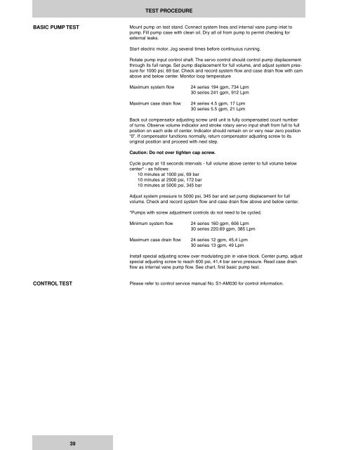
TEST PROCEDURE<br />
BASIC PUMP TEST<br />
Mount pump on test stand. Connect system lines and internal vane pump inlet to<br />
pump. Fill pump case with clean oil. Dry all oil from pump to permit checking for<br />
external leaks.<br />
Start electric motor. Jog several times before continuous running.<br />
Rotate pump input control shaft. The servo control should control pump displacement<br />
through its full range. Set pump displacement for full volume, and adjust system pressure<br />
for 1000 psi, 69 bar. Check and record system flow and case drain flow with cam<br />
above and below center. Monitor loop temperature<br />
Maximum system flow<br />
Maximum case drain flow<br />
24 series 194 gpm, 734 Lpm<br />
30 series 241 gpm, 912 Lpm<br />
24 series 4.5 gpm, 17 Lpm<br />
30 series 5.5 gpm, 21 Lpm<br />
Back out compensator adjusting screw until unit is fully compensated count number<br />
of turns. Observe volume indicator and stroke rotary servo input shaft from full to full<br />
position on each side of center. Indicator should remain on or very near zero position<br />
“0”. If compensator functions normally, return compensator adjusting screw to its<br />
original position and proceed with next step.<br />
Caution: Do not over tighten cap screw.<br />
Cycle pump at 10 seconds intervals - full volume above center to full volume below<br />
center* - as follows:<br />
10 minutes at 1000 psi, 69 bar<br />
10 minutes at 2500 psi, 172 bar<br />
10 minutes at 5000 psi, 345 bar<br />
Adjust system pressure to 5000 psi, 345 bar and set pump displacement for full<br />
volume. Check and record system flow and case drain flow above and below center.<br />
*Pumps with screw adjustment controls do not need to be cycled.<br />
Minimum system flow<br />
Maximum case drain flow<br />
24 series 160 gpm, 606 Lpm<br />
30 series 220.69 gpm, 385 Lpm<br />
24 series 12 gpm, 45,4 Lpm<br />
30 series 13 gpm, 49 Lpm<br />
Install special adjusting screw over modulating pin in valve block. Center pump, adjust<br />
special adjusting screw to reach 600 psi, 41,4 bar servo pressure. Read case drain<br />
flow as internal vane pump flow. See chart, first basic pump test.<br />
CONTROL TEST<br />
Please refer to control service manual No. S1-AM030 for control information.<br />
39


