

LT3-00032-2-A - DDKS Industries, hydraulic components distributor
LT3-00032-2-A - DDKS Industries, hydraulic components distributor
LT3-00032-2-A - DDKS Industries, hydraulic components distributor

Create successful ePaper yourself
Turn your PDF publications into a flip-book with our unique Google optimized e-Paper software.
ASSEMBLY PROCEDURE<br />
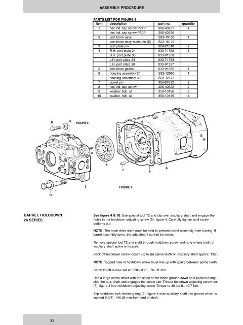
PARTS LIST FOR FIGURE 9<br />
item description part no. quantity<br />
1 hex. hd. cap screw P24P 306-40221 4<br />
hex. hd. cap screw P30P 306-40230<br />
2 port block assy. S23-15105 1<br />
port block assy. w/shuttle (S) S23-15127<br />
3 port plate pin 324-21610 2<br />
4 R.H. port plate 24 033-71752 1<br />
R.H. port plate 30 033-91238<br />
L.H. port plate 24 033-71753<br />
L.H. port plate 30 033-91237<br />
5 port block gasket 033-91085 1<br />
6 housing assembly 24 S23-12566 1<br />
housing assembly 30 S23-12175<br />
7 dowel pin 324-24832 2<br />
8 hex. hd. cap screw 306-40022 2<br />
9 washer, hdn. stl. 350-10136 2<br />
10 washer, hdn. stl. 350-10135 4<br />
FIGURE 9<br />
BARREL HOLDDOWN<br />
24 SERIES<br />
See figure 4 & 10. Use special tool T2 and slip over auxiliary shaft and engage the<br />
holes in the holddown adjusting screw (6), figure 4. Carefully tighten until screw<br />
bottoms out.<br />
NOTE: The main drive shaft must be held to prevent barrel assembly from turning. If<br />
barrel assembly turns, the adjustment cannot be made.<br />
Remove special tool T2 and sight through holddown screw and note where tooth of<br />
auxiliary shaft spline is located.<br />
Back off holddown screw loosen (5) to (6) spline teeth on auxiliary shaft approx. 135°.<br />
NOTE: Tapped hole in holddown screw must line up with space between spline teeth.<br />
Barrel lift-off is now set at .030”-.036”, .76-.91 mm.<br />
Use a large screw driver with the sides of the blade ground down so it passes along<br />
side the aux. shaft and engages the screw slot. Thread holddown adjusting screw lock<br />
(7), figure 4 into holddown adjusting screw. Torque to 30 lbs-ft., 40,7 Nm.<br />
Slip holddown lock retaining ring (8), figure 4 over auxiliary shaft into groove which is<br />
located 5-3/4”, 146.05 mm from end of shaft.<br />
25


