

LT3-00032-2-A - DDKS Industries, hydraulic components distributor
LT3-00032-2-A - DDKS Industries, hydraulic components distributor
LT3-00032-2-A - DDKS Industries, hydraulic components distributor

Create successful ePaper yourself
Turn your PDF publications into a flip-book with our unique Google optimized e-Paper software.
TEST PROCEDURE<br />
GENERAL REQUIREMENTS<br />
Maximum runout between pump shaft and electric motor shaft .003”, .076 mm total<br />
indicator reading.<br />
Electric motor speed - 1800 rpm.<br />
Inlet temperature - 120 0 -140 0 F, 500-580C.<br />
Inlet condition - main pump<br />
24 series 150 psi min., 10,3 bar min.<br />
30 series 225 psi min., 15,5 bar min.<br />
internal vane pump- 10” Hg to 5 psi, 254 mm Hg to .34 bar (except “S” version)<br />
Case pressure 55-75 psi, 3,81-5,19 bar.<br />
Fluid - 200 SSU at 100 0 F, 46 cSt at 40°C<br />
BASIC PUMP TEST<br />
Mount pump on test stand. Connect system lines and internal (externial with auxiliary<br />
drive) vane pump inlet to pump. Fill pump case with clean oil. Dry all oil from pump to<br />
permit checking for external leaks.<br />
Start electric motor. Jog several times before continuous running.<br />
Rotate pump input control shaft. The servo control should control pump displacement<br />
through its full range. Set pump displacement for full volume, and adjust system pressure<br />
for 1000 psi, 69 bar. Check and record system flow and case drain flow with cam<br />
above and below center. Monitor loop temperature.<br />
Maximum system flow<br />
Maximum case drain flow<br />
24 series 194 gpm, 734 Lpm<br />
30 series 241 gpm, 912 Lpm<br />
24 series 4.5 gpm, 17 Lpm<br />
30 series 5.5 gpm, 21 Lpm<br />
Back out compensator adjusting screw until unit is fully compensated count number<br />
of turns. Observe volume indicator and stroke rotary servo input shaft from full to full<br />
position on each side of center. Indicator should remain on or very near zero position<br />
“0”. If compensator functions normally, return compensator adjusting screw to its<br />
original position and proceed with next step.<br />
Caution: Do not over tighten cap screw.<br />
Cycle pump at 10 second intervals - full volume above center to full volume below<br />
center* - as follows:<br />
10 minutes at 1000 psi, 69 bar<br />
10 minutes at 2500 psi, 172 bar<br />
10 minutes at 5000 psi, 345 bar<br />
*Pumps with screw adjustment controls do not need to be cycled.<br />
Adjust system pressure to 5000 psi, 345 bar and set pump displacement for full<br />
volume. Check and record system flow and case drain flow above and below center.<br />
Minimum system flow<br />
Maximum case drain flow<br />
24 series 160 gpm, 606 Lpm<br />
30 series 220.69 gpm, 385 Lpm<br />
24 series 12 gpm, 45,4 Lpm<br />
30 series 13 gpm, 49 Lpm<br />
Set pump to compensate at 5000 psi, 345 bar. Servo pressure should be at least 600<br />
psi, 34,5 bar. Check and record internal vane pump flow.<br />
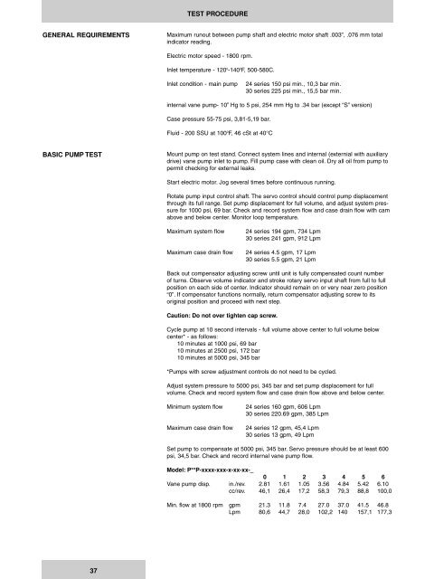
Model: P**P-xxxx-xxx-x-xx-xx-_<br />
0 1 2 3 4 5 6<br />
Vane pump disp. in./rev. 2.81 1.61 1.05 3.56 4.84 5.42 6.10<br />
cc/rev. 46,1 26,4 17,2 58,3 79,3 88,8 100,0<br />
Min. flow at 1800 rpm gpm 21.3 11.8 7.4 27.0 37.0 41.5 46.8<br />
Lpm 80,6 44,7 28,0 102,2 140 157,1 177,3<br />
37


