Chapter 6: Impedance measurements
Chapter 6: Impedance measurements
Chapter 6: Impedance measurements

Create successful ePaper yourself
Turn your PDF publications into a flip-book with our unique Google optimized e-Paper software.
Acoustic impedance <strong>measurements</strong><br />
frequencies f u and f p the response is measured not accurately. Therefore the<br />
response around these frequencies is estimated by interpolation.<br />
The amplitude response of the uncorrected impedance (black line Fig.<br />
6.10) can be converted in the free field response (Fig. 6.11) by:<br />
Z<br />
ff<br />
f<br />
sin( π )<br />
= fu<br />
Ztube,<br />
rigid<br />
π f<br />
(6.15)<br />
cos( )<br />
2 f<br />
p<br />
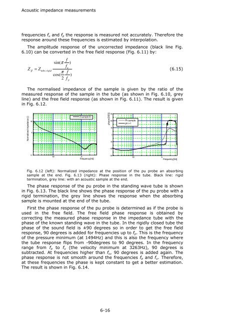
The normalised impedance of the sample is given by the ratio of the<br />
measured response of the sample in the tube (as shown in Fig. 6.10, grey<br />
line) and the free field response (as shown in Fig. 6.11). The result is given<br />
in Fig. 6.12.<br />
Normalised impedance [-]<br />
100<br />
10<br />
1<br />
Z sample lin<br />
phase [DEG]<br />
150<br />
100<br />
50<br />
0<br />
-50<br />
Ph sample<br />
ph r=1<br />
-100<br />
0,1<br />
100 1k<br />
Frequency [Hz]<br />
-150<br />
100 1k<br />
Frequency [Hz]<br />
Fig. 6.12 (left): Normalized impedance at the position of the pu probe an absorbing<br />
sample at the end. Fig. 6.13 (right): Phase response in the tube. Black line: rigid<br />
termination, grey line: with an acoustic sample at the end.<br />
The phase response of the pu probe in the standing wave tube is shown<br />
in Fig. 6.13. The black line shows the phase response of the pu probe with a<br />
rigid termination, the grey line shows the response when the absorbing<br />
sample is mounted at the end of the tube.<br />
First the phase response of the pu probe is determined as if the probe is<br />
used in the free field. The free field phase response is obtained by<br />
correcting the measured phase response in the impedance tube with the<br />
phase of the known standing wave in the tube. In the rigidly closed tube the<br />
phase of the sound field is ±90 degrees so in order to get the free field<br />
response, 90 degrees is added for frequencies up to f p . This is the frequency<br />
of the pressure minimum (at 1494Hz) and this is also the frequency where<br />
the tube response flips from -90degrees to 90 degrees. In the frequency<br />
range from f p to f u (the velocity minimum at 3263Hz), 90 degrees is<br />
subtracted. At frequencies higher than f u , 90 degrees is added again. The<br />
phase response is not smooth around the frequencies f p and f u . Therefore,<br />
at these frequencies the phase is kept constant to get a better estimation.<br />
The result is shown in Fig. 6.14.<br />
6-16