Chapter 6: Impedance measurements
Chapter 6: Impedance measurements
Chapter 6: Impedance measurements

Create successful ePaper yourself
Turn your PDF publications into a flip-book with our unique Google optimized e-Paper software.
Acoustic impedance <strong>measurements</strong><br />
dB(V)<br />
-60 pressure response<br />
silent<br />
-70<br />
PSD free field<br />
R=1<br />
-80<br />
dB(V)<br />
-50<br />
-60<br />
-70<br />
-90<br />
-100<br />
-110<br />
-120<br />
-130<br />
10 100 1k 10k<br />
Frequency [Hz]<br />
-80<br />
-90<br />
-100<br />
-110<br />
-120<br />
velocity response<br />
silent<br />
Free field<br />
R=1<br />
100 1k 10k<br />
Frequency [Hz]<br />
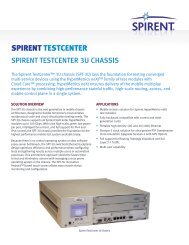
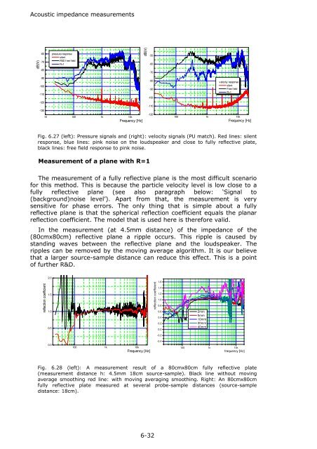
Fig. 6.27 (left): Pressure signals and (right): velocity signals (PU match). Red lines: silent<br />
response, blue lines: pink noise on the loudspeaker and close to fully reflective plate,<br />
black lines: free field response to pink noise.<br />
Measurement of a plane with R=1<br />
The measurement of a fully reflective plane is the most difficult scenario<br />
for this method. This is because the particle velocity level is low close to a<br />
fully reflective plane (see also paragraph below: ‘Signal to<br />
(background)noise level’). Apart from that, the measurement is very<br />
sensitive for phase errors. The only thing that is simple about a fully<br />
reflective plane is that the spherical reflection coefficient equals the planar<br />
reflection coefficient. The model that is used here is therefore valid.<br />
In the measurement (at 4.5mm distance) of the impedance of the<br />
(80cmx80cm) reflective plane a ripple occurs. This ripple is caused by<br />
standing waves between the reflective plane and the loudspeaker. The<br />
ripples can be removed by the moving average algorithm. It is our believe<br />
that a larger source-sample distance can reduce this effect. This is a point<br />
of further R&D.<br />
reflection coefficient<br />
2.0<br />
1.5<br />
1.0<br />
0.5<br />
reflection coefficient<br />
1.6<br />
1.4<br />
1.2<br />
1.0<br />
0.8<br />
0.6<br />
0.4<br />
0.2<br />
0.0<br />
2mm<br />
5mm<br />
10mm<br />
20mm<br />
40mm<br />
-0.2<br />
0.0<br />
100 1k 10k<br />
Frequency [Hz]<br />
-0.4<br />
100 1k 10k<br />
frequency [Hz]<br />
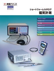
Fig. 6.28 (left): A measurement result of a 80cmx80cm fully reflective plate<br />
(measurement distance h: 4.5mm 18cm source-sample). Black line without moving<br />
average smoothing red line: with moving averaging smoothing. Right: An 80cmx80cm<br />
fully reflective plate measured at several probe-sample distances (source-sample<br />
distance: 18cm).<br />
6-32