Chapter 6: Impedance measurements
Chapter 6: Impedance measurements
Chapter 6: Impedance measurements

Create successful ePaper yourself
Turn your PDF publications into a flip-book with our unique Google optimized e-Paper software.
Acoustic impedance <strong>measurements</strong><br />
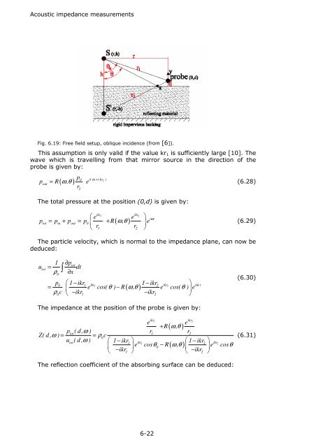
Fig. 6.19: Free field setup, oblique incidence (from [6]).<br />
This assumption is only valid if the value kr 1 is sufficiently large [10]. The<br />
wave which is travelling from that mirror source in the direction of the<br />
probe is given by:<br />
p<br />
p R , e<br />
0 ω + 2<br />
( ω θ )<br />
i( t kr )<br />
out<br />
= (6.28)<br />
r2<br />
The total pressure at the position (0,d) is given by:<br />
ikr1 ikr2<br />
⎛ e<br />
e ⎞<br />
ptot = pin + pout = p0<br />
⎜ + R ( ω, θ ) ⎟e<br />
⎝ r1 r2<br />
⎠<br />
iωt<br />
(6.29)<br />
The particle velocity, which is normal to the impedance plane, can now be<br />
deduced:<br />
u<br />
tot<br />
1<br />
=<br />
ρ<br />
0<br />
∫<br />
∂ptot<br />
dt<br />
∂x<br />
p ⎛ 1−<br />
ikr 1−<br />
ikr ⎞<br />
= ⎜ e cos( θ ) − R ( ω, θ ) e cos( θ ) ⎟e<br />
ρ0c ⎝ −ikr1 −ikr2<br />
⎠<br />
0 1 ikr1 2 ikr2<br />
iω<br />
t<br />
(6.30)<br />
The impedance at the position of the probe is given by:<br />
ikr1 ikr2<br />
e<br />
e<br />
+ R ( ω,<br />
θ )<br />
p<br />
tot( d , ω ) r1 r2<br />
Z( d , ω ) = = ρ0c<br />
u<br />
tot( d , ω ) ⎛ 1−<br />
ikr ⎞<br />
1 ikr<br />
⎛ 1−<br />
ikr ⎞<br />
1 2 ikr2<br />
⎜ ⎟e cosθ0<br />
− R ( ω, θ ) ⎜ ⎟e cosθ<br />
⎝ −ikr1 ⎠ ⎝ −ikr2<br />
⎠<br />
(6.31)<br />
The reflection coefficient of the absorbing surface can be deduced:<br />
6-22