Chapter 6: Impedance measurements
Chapter 6: Impedance measurements
Chapter 6: Impedance measurements

Create successful ePaper yourself
Turn your PDF publications into a flip-book with our unique Google optimized e-Paper software.
Acoustic impedance <strong>measurements</strong><br />
Phase [DEG]<br />
30<br />
20<br />
10<br />
0<br />
Phase sample corr [deg]<br />
30<br />
0<br />
-30<br />
-10<br />
-60<br />
-20<br />
-90<br />
-30<br />
100 1k<br />
Frequency [Hz]<br />
100 1k<br />
Frequency [Hz]<br />
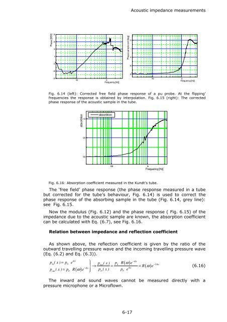
Fig. 6.14 (left): Corrected free field phase response of a pu probe. At the flipping’<br />
frequencies the response is obtained by interpolation. Fig. 6.15 (right): The corrected<br />
phase response of the acoustic sample in the tube.<br />
absorbtion<br />
1,0<br />
absorbtion<br />
0,5<br />
0,0<br />
100 1k<br />
Frequency [Hz]<br />
Fig. 6.16: Absorption coefficient measured in the Kundt’s tube.<br />
The ‘free field’ phase response (the phase response measured in a tube<br />
but corrected for the tube’s behaviour, Fig. 6.14) is used to correct the<br />
phase response of the absorbing sample in the tube (Fig. 6.14, grey line):<br />
see Fig. 6.15.<br />
Now the modulus (Fig. 6.12) and the phase response ( Fig. 6.15) of the<br />
impedance due to the acoustic sample are known, the absorption coefficient<br />
can be calculated with Eq. (6.7), see Fig. 6.16.<br />
Relation between impedance and reflection coefficient<br />
As shown above, the reflection coefficient is given by the ratio of the<br />
outward travelling pressure wave and the incoming travelling pressure wave<br />
(Eq. (6.2) and Eq. (6.3)).<br />
( ω)<br />
p ( x ) = p e ⎫⎪ p R e<br />
→ = =<br />
p ( x ) = p R e ⎪⎭<br />
ikx<br />
−ikx<br />
in 0 p<br />
out<br />
( x ) 0 −2ikx<br />
R<br />
ikx<br />
( ω)<br />
e<br />
−ikx<br />
⎬<br />
out 0 ( ω)<br />
p<br />
in( x ) p0<br />
e<br />
(6.16)<br />
The inward and sound waves cannot be measured directly with a<br />
pressure microphone or a Microflown.<br />
6-17