Chapter 6: Impedance measurements
Chapter 6: Impedance measurements
Chapter 6: Impedance measurements

Create successful ePaper yourself
Turn your PDF publications into a flip-book with our unique Google optimized e-Paper software.
Acoustic impedance <strong>measurements</strong><br />
For highly sound absorbing materials, the absorption coefficient can<br />
exceed a value of one because of extra energy loss due to edge effects and<br />
diffraction. This can also be the case if the sound field is non-diffuse.<br />
Various standards state that at least 20 modes of vibration in the chamber<br />
are required in the lowest frequency band. As a result the room volume<br />
must be quite large. Nevertheless considerable differences have been<br />
observed for <strong>measurements</strong> on the same test materials in different<br />
reverberation chambers.<br />
It has been shown that if the total energy (that is the pressure plus the<br />
velocity vector) is measured, the accuracy of the <strong>measurements</strong> increases<br />
[33].<br />
<strong>Impedance</strong> tube methods<br />
Although a number of measurement techniques can be used to quantify<br />
the sound absorbing behaviour, most often the determination of the<br />
properties takes place in a standing wave tube. This is because in a tube the<br />
mathematic problem becomes one-dimensional (in a certain bandwidth):<br />
sound waves can only propagate in one direction. This makes the<br />
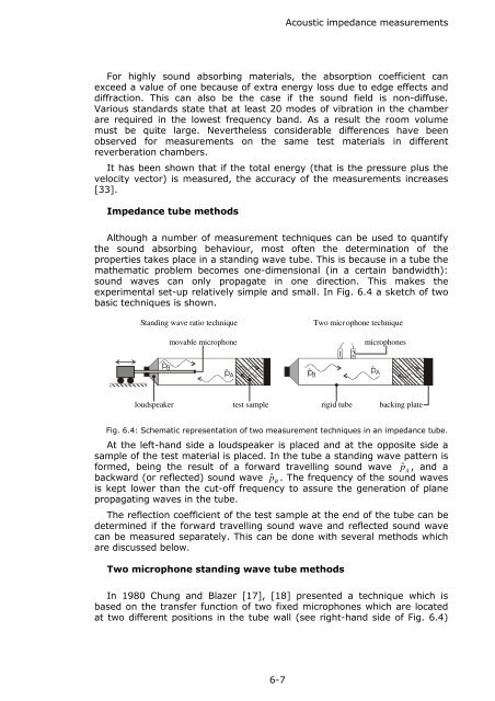
experimental set-up relatively simple and small. In Fig. 6.4 a sketch of two<br />
basic techniques is shown.<br />
Standing wave ratio technique<br />
Two micr ophone technique<br />
movable microphone<br />
1 2<br />
microphones<br />
loudspeaker test sample rigid tube backing plate<br />
Fig. 6.4: Schematic representation of two measurement techniques in an impedance tube.<br />
At the left-hand side a loudspeaker is placed and at the opposite side a<br />
sample of the test material is placed. In the tube a standing wave pattern is<br />
formed, being the result of a forward travelling sound wave p ˆ A<br />
, and a<br />
backward (or reflected) sound wave p ˆ B<br />
. The frequency of the sound waves<br />
is kept lower than the cut-off frequency to assure the generation of plane<br />
propagating waves in the tube.<br />
The reflection coefficient of the test sample at the end of the tube can be<br />
determined if the forward travelling sound wave and reflected sound wave<br />
can be measured separately. This can be done with several methods which<br />
are discussed below.<br />
Two microphone standing wave tube methods<br />
In 1980 Chung and Blazer [17], [18] presented a technique which is<br />
based on the transfer function of two fixed microphones which are located<br />
at two different positions in the tube wall (see right-hand side of Fig. 6.4)<br />
6-7