27 Operator's Manual.. - Marlow-Hunter, LLC
27 Operator's Manual.. - Marlow-Hunter, LLC
27 Operator's Manual.. - Marlow-Hunter, LLC

You also want an ePaper? Increase the reach of your titles
YUMPU automatically turns print PDFs into web optimized ePapers that Google loves.
<strong>Hunter</strong> <strong>27</strong> • DC Electric<br />
The negative terminal of all banks are attached to the DC<br />
Ground connection on the engine. This system, known as<br />
the negative ground system, is the approved system for<br />
marine DC electrical systems. The battery wiring system<br />
has two color coded wires. The yellow wire is the ground<br />
(negative), and the red wire is (positive).<br />
To avoid explosions, do not use jumper cables and a<br />
booster battery to start the engine. If batteries are dead,<br />
then remove and recharge them ashore.<br />
Batteries produce hydrogen and oxygen gasses when<br />
they are being charged. These explosive gasses escape<br />
through the vent/fill caps and may form an explosive<br />
atmosphere around the battery if ventilation is poor. This<br />
gas may remain around the battery for several hours after<br />
charging. Sparks or flame can ignite the gas and cause<br />
an explosion.<br />
MFG/PN Group Size Volts Qty<br />
Exide Prevailer<br />
31 12 2<br />
PV-31<br />
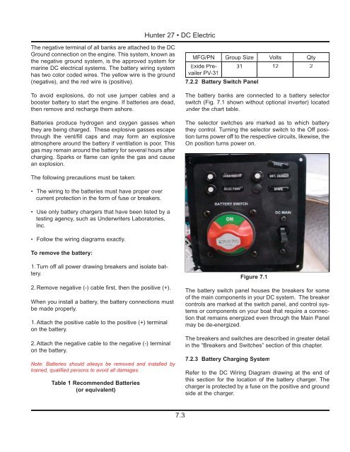
7.2.2 Battery Switch Panel<br />
The battery banks are connected to a battery selector<br />
switch (Fig. 7.1 shown without optional inverter) located<br />
under the chart table.<br />
The selector switches are marked as to which battery<br />
they control. Turning the selector switch to the Off position<br />
turns power off to the respective circuits, likewise, the<br />
On position turns power on.<br />
The following precautions must be taken:<br />
• The wiring to the batteries must have proper over<br />
current protection in the form of fuse or breakers.<br />
• Use only battery chargers that have been listed by a<br />
testing agency, such as Underwriters Laboratories,<br />
Inc.<br />
• Follow the wiring diagrams exactly.<br />
To remove the battery:<br />
1. Turn off all power drawing breakers and isolate battery.<br />
2. Remove negative (-) cable first, then the positive (+).<br />
When you install a battery, the battery connections must<br />
be made properly.<br />
1. Attach the positive cable to the positive (+) terminal<br />
on the battery.<br />
2. Attach the negative cable to the negative (-) terminal<br />
on the battery.<br />
Note: Batteries should always be removed and installed by<br />
trained, qualified persons to avoid all damages.<br />
Table 1 Recommended Batteries<br />
(or equivalent)<br />
Figure 7.1<br />
The battery switch panel houses the breakers for some<br />
of the main components in your DC system. The breaker<br />
controls are marked at the switch panel, and control systems<br />
or components on your boat that require a connection<br />
that remains energized even through the Main Panel<br />
may be de-energized.<br />
The breakers and switches are described in greater detail<br />
in the “Breakers and Switches” section of this chapter.<br />
7.2.3 Battery Charging System<br />
Refer to the DC Wiring Diagram drawing at the end of<br />
this section for the location of the battery charger. The<br />
charger is protected by a fuse on the positive and ground<br />
side at the charger.<br />
7.3