27 Operator's Manual.. - Marlow-Hunter, LLC
27 Operator's Manual.. - Marlow-Hunter, LLC
27 Operator's Manual.. - Marlow-Hunter, LLC

Create successful ePaper yourself
Turn your PDF publications into a flip-book with our unique Google optimized e-Paper software.
12V DC<br />
PORT<br />
DC AMPS<br />
STBD<br />
START-STOP/PRIME<br />
24V DC<br />
STATUS<br />
<strong>Hunter</strong> <strong>27</strong> • DC Electric<br />
the top of mast. This should be on when underway with<br />
sail power only.<br />
The anchor light is a 360 ° light mounted at the top<br />
of the mast and should only be on when anchored.<br />
Lighting circuits and locations are outlined in the end of<br />
this chapter.<br />
7.3.3 Electric Cooler (Option)<br />
to the manual position.<br />
2. Another procedure to be used in extreme circumstances<br />
involves locating the float switch and manually rotating<br />
the float handle on the side of the float switch to simulate<br />
the float switch being underwater. This will energize the<br />
pump and the pump will operate.<br />
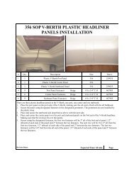
Main Distribution Panel<br />
DC DISTRIBUTION PANEL<br />
The reset marked “Cooler”, on the backside of<br />
12 Volt DC Panel supplies power to the cooler<br />
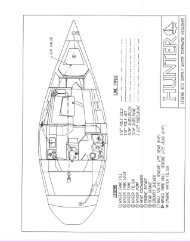
aboard your boat. Refer to Interior arrangement<br />
layout on page 4.16 for the location of the cooler.<br />
Battery Switch Panel<br />
12 VOLT D.C.<br />
BATTERY TEST<br />
7.3.3.1 Basic Cooler Operation<br />
1. On standard battery charger model, turn on house<br />
battery selector switch ( aft cabin).<br />
2. Turn on Main DC breaker at Battery Swtich Panel.<br />
3. Set Thermostat to desired temperature.<br />
Note: If leaving unit on when away from boat be sure<br />
shore power cables are connected and battery charger<br />
is on to prevent battery drain.<br />
Note: Consult product manual for operating the refrigerator<br />
and other information on the unit.<br />
7.3.4 Bilge Pump Systems<br />
Your boat is equipped with 1 main bilge pump and<br />
1 (Optional) emergency bilge pump. For locations<br />
of the bilge pump systems, consult your Mechanical<br />
Arrangement Drawing or the Sanitary Systems Drawing.<br />
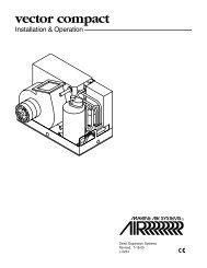
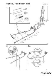
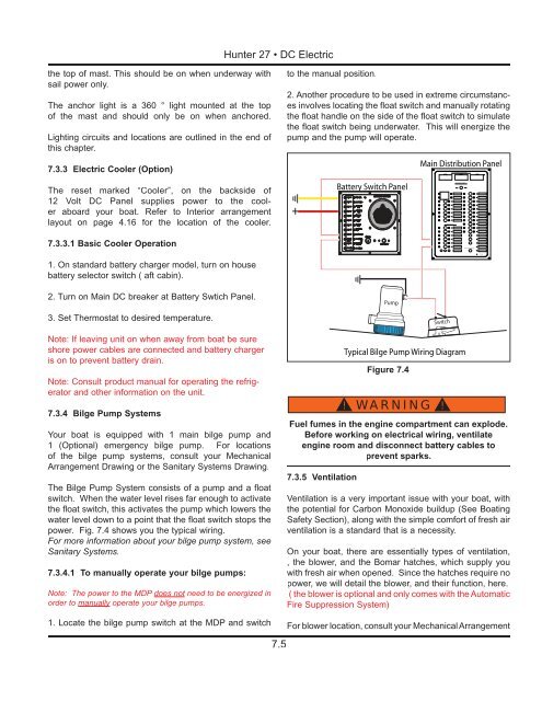
The Bilge Pump System consists of a pump and a float<br />
switch. When the water level rises far enough to activate<br />
the float switch, this activates the pump which lowers the<br />
water level down to a point that the float switch stops the<br />
power. Fig. 7.4 shows you the typical wiring.<br />
For more information about your bilge pump system, see<br />
Sanitary Systems.<br />
7.3.4.1 To manually operate your bilge pumps:<br />
Note: The power to the MDP does not need to be energized in<br />
order to manually operate your bilge pumps.<br />
1. Locate the bilge pump switch at the MDP and switch<br />
Typical Bilge Pump Wiring Diagram<br />
Figure 7.4<br />
! WARNING !<br />
Fuel fumes in the engine compartment can explode.<br />
Before working on electrical wiring, ventilate<br />
engine room and disconnect battery cables to<br />
prevent sparks.<br />
7.3.5 Ventilation<br />
Ventilation is a very important issue with your boat, with<br />
the potential for Carbon Monoxide buildup (See Boating<br />
Safety Section), along with the simple comfort of fresh air<br />
ventilation is a standard that is a necessity.<br />
On your boat, there are essentially types of ventilation,<br />
, the blower, and the Bomar hatches, which supply you<br />
with fresh air when opened. Since the hatches require no<br />
power, we will detail the blower, and their function, here.<br />
( the blower is optional and only comes with the Automatic<br />
Fire Suppression System)<br />
For blower location, consult your Mechanical Arrangement<br />
7.5