

In-Sight 7000 Series Vision System Installation Manual - Automation ...
In-Sight 7000 Series Vision System Installation Manual - Automation ...
In-Sight 7000 Series Vision System Installation Manual - Automation ...

Create successful ePaper yourself
Turn your PDF publications into a flip-book with our unique Google optimized e-Paper software.
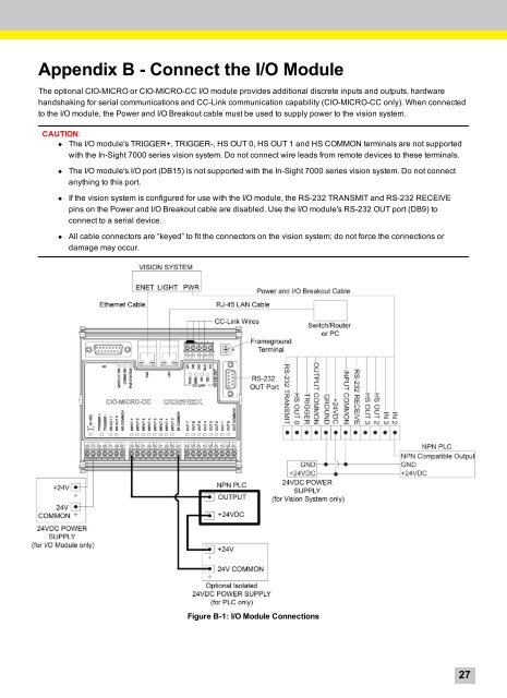
Appendix B - Connect the I/O Module<br />
The optional CIO-MICRO or CIO-MICRO-CC I/O module provides additional discrete inputs and outputs, hardware<br />
handshaking for serial communications and CC-Link communication capability (CIO-MICRO-CC only). When connected<br />
to the I/O module, the Power and I/O Breakout cable must be used to supply power to the vision system.<br />
CAUTION:<br />
• The I/O module's TRIGGER+, TRIGGER-, HS OUT 0, HS OUT 1 and HS COMMON terminals are not supported<br />
with the <strong>In</strong>-<strong>Sight</strong> <strong>7000</strong> series vision system. Do not connect wire leads from remote devices to these terminals.<br />
• The I/O module's I/O port (DB15) is not supported with the <strong>In</strong>-<strong>Sight</strong> <strong>7000</strong> series vision system. Do not connect<br />
anything to this port.<br />
• If the vision system is configured for use with the I/O module, the RS-232 TRANSMIT and RS-232 RECEIVE<br />
pins on the Power and I/O Breakout cable are disabled. Use the I/O module's RS-232 OUT port (DB9) to<br />
connect to a serial device.<br />
• All cable connectors are “keyed” to fit the connectors on the vision system; do not force the connections or<br />
damage may occur.<br />
Figure B-1: I/O Module Connections<br />
27


