LinkSwitch-HP Family - Codico
LinkSwitch-HP Family - Codico
LinkSwitch-HP Family - Codico

You also want an ePaper? Increase the reach of your titles
YUMPU automatically turns print PDFs into web optimized ePapers that Google loves.
<strong>LinkSwitch</strong>-<strong>HP</strong><br />
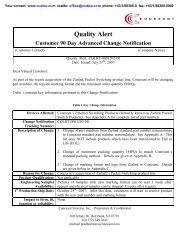
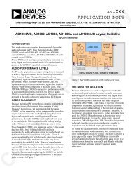
Frequency (kHz)<br />
Normalized Peak Current<br />
132<br />
f SW(LF)<br />
30<br />
100%<br />
50%<br />
25%<br />
V V C(MIN) C(MCM)<br />
V C(MAX)<br />
Compensation<br />
Voltage (∝ P OUT<br />
)<br />
Compensation<br />
Voltage (∝ P OUT<br />
)<br />
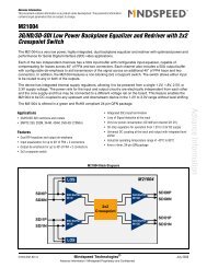
voltage is sampled after the turn-off of the internal switch to<br />
compensate for diode conduction time differences. Sampling<br />
time increases monotonically from 1.2 ms at no or light load to<br />
2.5 ms at full load. Sampled voltage is held until the next clock<br />
cycle. The output of S/H is fed to the error amplifier, once in<br />
regulation the sampled voltage is 2 V.<br />
BYPASS (BP) Programming<br />
This feature selects either hysteretic or latching OVP/OCP and<br />
OTP protection based on capacitor loading on the BYPASS pin.<br />
The shutdown type is determined at the device power-up as<br />
shown in Table 2.<br />
C BP<br />
0.47 mF 4.7 mF 47 mF<br />
OVP Latching Auto-Restart Latching<br />
Lost Regulation (SC,<br />
OC, Open-Loop<br />
Auto-Restart Auto-Restart Latching<br />
OTP Latching Hysteretic Latching<br />
Figure 5.<br />
PI-6722-032012<br />
Compensation Pin Characteristics (Multi-Mode Operation).<br />
typically 3% as long as the fault condition persists. In autorestart<br />
switching is disabled for t AR(OFF)1<br />
(typ. 1500 ms) when the<br />
FEEDBACK pin voltage has dropped below the auto-restart<br />
threshold V FB(AR)<br />
for the shutdown default delay time t AR(ON)<br />
(typ.<br />
35 ms). After this period switching is enabled again with the<br />
device entering soft-start (typ. 15 ms). For the first auto-restart<br />
off-period switching is disabled for a reduced time t AR(OFF)2<br />
(typ.<br />
150 ms) to reduce the power supply restart time during line<br />
cycling. Optionally the default shutdown delay time can be<br />
extended by adding a capacitor to the PROGRAM pin.<br />
Hysteretic Thermal Shutdown<br />
The thermal shutdown circuitry senses the controller die<br />
temperature. The threshold is set at 142 °C with a 75 °C<br />
hysteresis (both typical). Once the device temperature rises<br />
above 142 °C, the power MOSFET is disabled and remains<br />
disabled until the die temperature falls by 75 °C, at which point<br />
the device is re-enabled. The large hysteresis maintain the<br />
average temperature below the temperature rating of low cost<br />
CEM type PCB material in most cases.<br />
Safe Operating Area (SOA) Protection<br />
The device features a safe operating area (SOA) protection<br />
mode which disables MOSFET switching for 4 consecutive<br />
cycles in the event the peak switching current reaches the<br />
current limit in less than time t ON(SOA)<br />
. This prevents excessive<br />
drain currents during start-up and output short-circuit<br />
conditions by providing additional time for the primary<br />
inductance to reset. The SOA protection is disabled when the<br />
output voltage is within 10% of regulation voltage.<br />
Sample and Hold (S/H)<br />
The sample and hold block senses the output voltage at auxiliary<br />
winding during secondary rectifier on-time. The FEEDBACK pin<br />
Table 2.<br />
Current Limit Setting<br />
During power-up the cycle-by-cycle current limit is determined<br />
by measuring the resistor value connected to the PROGRAM<br />
pin by the measurement is performed by applying 1.25 V (see<br />
Figure 8). The current limit can be set between 40% to 100% in<br />
steps of 10% as shown in Table 3. After the current limit is set<br />
the PROGRAM pin voltage is reduced to ~0 in order to minimize<br />
power dissipation.<br />
Table 3.<br />
Shutdown Type vs. Value of BYPASS Pin Capacitance.<br />
I PD<br />
R PD<br />
I LIMIT(NORM)<br />
I PD<br />
R PD<br />
I LIMIT(NORM)<br />
mA kW % mA kW %<br />
10 124 100 54 23.2 60<br />
16 78.7 90 83 15.0 50<br />
24 52.3 80 125 10.0 40<br />
36 34.8 70<br />
Current Limit Selection vs. Program Pin Resistor Value.<br />
Programmable Shutdown Delay<br />
The default auto-restart shutdown delay time t SD(AR)<br />
(typ. 35 ms)<br />
can optionally be extended by connecting a capacitor to the<br />
PROGRAM pin. Once a lost regulation fault is detected the<br />
PROGRAM pin voltage is cycled 128 times between V PD(DL)<br />
(typ.<br />
0.5 V) and V PD(DU)<br />
(typ. 1.2 V) as shown in Figure 8. Figure 6<br />
depicts the relationship between extended shutdown delay<br />
time, added PROGRAM pin capacitor and current limit<br />
programming resistor.<br />
Remote On/Off and Fast AC Reset<br />
The PROGRAM pin can be used to turn on/off the device<br />
remotely. If the voltage on the pin is set to 1.3 V externally, the<br />
device stops switching. After releasing the PROGRAM pin the<br />
PROGRAM pin device commences switching when the voltage<br />
drops below 0.55 V.<br />
4<br />
Rev. A 07/12<br />
www.powerint.com