- Page 2:
Metric & American INDUSTRIAL POWER
- Page 5 and 6:
General Overview Stock Bearing Prod
- Page 7 and 8:
Specialty Products Linear Bearings
- Page 9 and 10:
Mounted Ball Bearings Product Overv
- Page 11 and 12:
Ball Bearing Selection Criteria Loa
- Page 13 and 14:
Mounted Ball Bearing Interchange No
- Page 15 and 16:
Mounted Ball Bearing Interchange No
- Page 17 and 18:
Pillow Block UCP 200 Gold Series No
- Page 19 and 20:
Pillow Block RAK 200 Gold Series No
- Page 21 and 22:
Pillow Block VAK 200 Gold Series No
- Page 23 and 24:
Pillow Block SW 200 Gold Series Nor
- Page 25 and 26:
Pillow Block UKP 200 Silver Series
- Page 27 and 28:
Pillow Block CLRAK 200 Silver Serie
- Page 29 and 30:
Pillow Block RAKH 200 Gold Series N
- Page 31 and 32:
Pillow Block RAKHL 200 Gold Series
- Page 33 and 34:
Medium Duty Pillow Block PX and PXL
- Page 35 and 36:
Pressed Steel Pillow Block BS 200 G
- Page 37 and 38:
Light Duty Pillow Block UP 000 Silv
- Page 39 and 40:
Tapped Base Pillow Block TB 200 Gol
- Page 41 and 42:
Tapped Base Pillow Block PA 200 Gol
- Page 43 and 44:
Tapped Base Pillow Block SWG 200 Go
- Page 45 and 46:
Tapped Base Pillow Block GSHTB 200
- Page 47 and 48:
4-Bolt Flange UCF 200 Gold Series N
- Page 49 and 50:
4-Bolt Flange FWS 200 Gold Series N
- Page 51 and 52:
4-Bolt Flange GSHF 200 Silver Serie
- Page 53 and 54:
Medium Duty 4-Bolt Flange UCFX Silv
- Page 55 and 56:
Piloted 4-Bolt Flange UCFC 200 Gold
- Page 57 and 58:
Piloted 4-Bolt Flange FCF 200 Gold
- Page 59 and 60:
Piloted 4-Bolt Flange GSHFC 200 Sil
- Page 61 and 62:
Piloted 4-Bolt Flange CLFC 200 Silv
- Page 63 and 64:
Piloted 4-Bolt Flange FWSN 200 Gold
- Page 65 and 66:
Piloted 4-Bolt Flange RVFW 200 Gold
- Page 67 and 68:
3-Bolt Flanged Bracket FB 200 Gold
- Page 69 and 70:
3-Bolt Flanged Bracket GSHFB 200 Si
- Page 71 and 72:
Ductile 3-Bolt Flange F3X 200 Gold
- Page 73 and 74:
3-Bolt Flange DFW 200 Gold Series N
- Page 75 and 76:
Pressed Steel Flange Units BF Gold
- Page 77 and 78:
Pressed Steel 3-Bolt Flange DBF 200
- Page 79 and 80:
2-Bolt Flange UCFL 200 Gold Series
- Page 81 and 82:
2-Bolt Flange UCFT 200 Gold Series
- Page 83 and 84:
2-Bolt Flange OWF 200 Gold Series N
- Page 85 and 86:
2 Bolt Piloted Flange OWFZ 200 Gold
- Page 87 and 88:
2-Bolt Flange OWFS 200 Gold Series
- Page 89 and 90:
2-Bolt Flange HCFJT 200 Silver Seri
- Page 91 and 92:
2-Bolt Flange GSHFT 200 Silver Seri
- Page 93 and 94:
2-Bolt Flange UKFL 200 Silver Serie
- Page 95 and 96:
2-Bolt Flange CLFL 200 Silver Serie
- Page 97 and 98:
Medium Duty 2-Bolt Flange FLX Silve
- Page 99 and 100:
2-Bolt Flange OWFK 200 Gold Series
- Page 101 and 102:
2-Bolt Flange LF 200 Gold Series No
- Page 103 and 104:
Ductile 2-Bolt Flange FX 200 Gold S
- Page 105 and 106:
Pressed Steel Flange OBF 200 Gold S
- Page 107 and 108:
Pressed Steel Flange with Rubber Is
- Page 109 and 110:
Swivel Flange WSFL 200 Gold Series
- Page 111 and 112:
Take-Up UCT 200 Gold Series Normal
- Page 113 and 114:
Take-Up HCT 200 Gold Series Normal
- Page 115 and 116:
Take-Up GSHT 200 Silver Series Thin
- Page 117 and 118:
Wide Slot Take-Up WS 200 Gold Serie
- Page 119 and 120:
Wide Slot Take-Up CLWS 200 Silver S
- Page 121 and 122:
Take-Up SPK 200 Gold Series Normal
- Page 123 and 124:
Hanger Bearing HA 200 Gold Series N
- Page 125 and 126:
Cylindrical Units HLW 200 Gold Seri
- Page 127 and 128:
Ball Bearing Inserts UC 200 Gold Se
- Page 129 and 130:
Ball Bearing Inserts SB 200 Gold Se
- Page 131 and 132:
Ball Bearing Inserts HC 200 Gold Se
- Page 133 and 134:
Ball Bearing Inserts SA 200 Gold Se
- Page 135 and 136:
Medium Duty Ball Bearing Inserts UC
- Page 137 and 138:
Ball Bearing Inserts and Accessorie
- Page 139 and 140:
Ball Bearing Inserts CL 200 Silver
- Page 141 and 142:
Ball Bearing Inserts U000 Silver Se
- Page 143 and 144:
Stainless, Thermoplastic & Nickel P
- Page 145 and 146:
Stainless Steel Pillow Block SUCSP
- Page 147 and 148:
Thermoplastic Pillow Block SUCTP 20
- Page 149 and 150:
Stainless Steel Tapped Base SUCSPA
- Page 151 and 152:
Thermoplastic Tapped Base SUCTTB 20
- Page 153 and 154:
Stainless Steel 4-Bolt Flange SUCSF
- Page 155 and 156:
Thermoplastic 4-Bolt Flange Units S
- Page 157 and 158:
Stainless Steel Piloted 4-Bolt Flan
- Page 159 and 160:
Stainless Steel 2-Bolt Flange SUCSF
- Page 161 and 162:
Thermoplastic 2-Bolt Flange SUCTFL
- Page 163 and 164:
Stainless Steel 3-Bolt Flanged Brac
- Page 165 and 166:
Thermoplastic 3-Bolt Flange Bracket
- Page 167 and 168:
Stainless Steel Take-Up SUCST 200 S
- Page 169 and 170:
Thermoplastic Take-Up Units SUCTT 2
- Page 171 and 172:
PBT Covers for Thermoplastic Housin
- Page 173 and 174:
Stainless Steel Ball Bearing Insert
- Page 175 and 176:
Stainless Steel Ball Bearing Insert
- Page 177 and 178:
More Split Pillow Blocks & Special
- Page 179 and 180:
Pillow Block Housings SAF 500 Serie
- Page 181 and 182:
Pillow Block Housings SAF 600 Serie
- Page 183 and 184:
SAF Split Block Accessories Tac Sea
- Page 185 and 186:
Pillow Block Housings SAF 200 Serie
- Page 187 and 188:
Pillow Block Housings SAF 300 Serie
- Page 189 and 190:
Pillow Block Housings SDAF 500 Seri
- Page 191 and 192:
Pillow Block Housings SDAF 200 Seri
- Page 193 and 194:
Pillow Block Housings SAF 000 Serie
- Page 195 and 196:
Pillow Block Housings SDAF 230 Seri
- Page 197 and 198:
Pillow Block Housings SDAF 231 Seri
- Page 199 and 200:
Pillow Block Housings SDAF 232 Seri
- Page 201 and 202:
Plummer Block Housings SNG 500 Seri
- Page 203 and 204:
Metric Plummer Block SNG 500-600 Se
- Page 205 and 206:
Plummer Block Housings SNG 600 Seri
- Page 207 and 208: Plummer Block Housings SN 500 Serie
- Page 209 and 210: Plummer Block Housings SN 600 Serie
- Page 211 and 212: Plummer Block Housings SN 200 Serie
- Page 213 and 214: Plummer Block Housings SN 300 Serie
- Page 215 and 216: Bronze Journal Bearings DIN 505 Ser
- Page 217 and 218: Plummer Block Housings SD 3100 TS S
- Page 219 and 220: Flanged Housings 722500 Series - 3
- Page 221 and 222: HSPA Take-Up Units HSPA Take-Up Uni
- Page 223 and 224: Plummer Block Housings HFO 200 Seri
- Page 225 and 226: Double Bearing Housings PDNF Series
- Page 227 and 228: Self-Aligning Ball Bearings 2200 &
- Page 229 and 230: Spherical Roller Bearings 223 Serie
- Page 231 and 232: Spherical Roller Bearings 231 Serie
- Page 233 and 234: Adapter Interchange H-Type SNW Type
- Page 235 and 236: Adapter Sleeves SNW 00 Series Inch
- Page 237 and 238: Adapter Sleeves SNP 3000 Series Inc
- Page 239 and 240: Adapter Sleeves H300 Series (for 22
- Page 241 and 242: Adapter Sleeves H3200 Series Metric
- Page 243 and 244: Hydraulic Adapter Sleeves OH3200 Se
- Page 245 and 246: Metric Lock Nuts KM Series KML Seri
- Page 247 and 248: Inch Lock Nuts N00 Series AN00 Seri
- Page 249 and 250: GUK Type Lock Nuts Self-Locking nut
- Page 251 and 252: Inch Lock Washers W00 Series W000 S
- Page 253 and 254: Withdrawal Sleeves Metric Bores d T
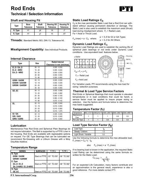
- Page 255 and 256: Roller Bearings Eich Roller Bearing
- Page 257: Metric Rod Ends Rod ends are availa
- Page 261 and 262: Metric Rod Ends GIS Type Heavy Duty
- Page 263 and 264: Metric Rod Ends GIRS Type Stainless
- Page 265 and 266: Metric Rod Ends GIXSW Type Heat Tre
- Page 267 and 268: Metric Rod Ends EI Type Steel on St
- Page 269 and 270: Metric Rod Ends EI..D SS Type Stain
- Page 271 and 272: Metric Hydraulic Rod Ends FPR..U Ty
- Page 273 and 274: Metric Rod Ends Inquiry Template Fa
- Page 275 and 276: Winkel Combined Bearings and Profil
- Page 277 and 278: Linear Systems The Economical Solut
- Page 279 and 280: Fixed Axial Bearing Combined Bearin
- Page 281 and 282: Combined Bearings Adjustable Eccent
- Page 283 and 284: Combined Bearings Shim Adjustable A
- Page 285 and 286: Heavy Duty Combined Bearings Type 3
- Page 287 and 288: Axial Bearing Adjustable Jumbo Comb
- Page 289 and 290: Combined Bearings Type JC Adjusting
- Page 291 and 292: Single Profiles Standard Series All
- Page 293 and 294: Single Profiles Precision Series Al
- Page 295 and 296: Duplex Profiles Standard Series Mat
- Page 297 and 298: Vulkollan Combined Bearings Part No
- Page 299 and 300: Vulkollan Combined Bearings Part No
- Page 301 and 302: Profiles for Vulkollan & Polyamide
- Page 303 and 304: Polyamide Combined Bearings Part No
- Page 305 and 306: Chain Selection Criteria Guide Line
- Page 307 and 308: Metric (British Standard) Roller Ch
- Page 309 and 310:
Metric Attachment Chain E-Series -
- Page 311 and 312:
Metric Attachment Chain E-Series -
- Page 313 and 314:
Stainless Steel Roller Chain E-Seri
- Page 315 and 316:
Attachment Chain Worksheet Overview
- Page 317 and 318:
Metric Roller Chain with Straight S
- Page 319 and 320:
Lube Free Roller Chain Marathon Ser
- Page 321 and 322:
Lube Free - Stainless Roller Chain
- Page 323 and 324:
Accumulator Chain For Automated Con
- Page 325 and 326:
Agricultural & Lumber Roller Chain
- Page 327 and 328:
Metric Conveyor Chain Solid Bearing
- Page 329 and 330:
Metric Conveyor Chain Deep Link Sol
- Page 331 and 332:
Metric Conveyor Chain Deep Link Hol
- Page 333 and 334:
Metric Sprockets ISO 03B Hub Type B
- Page 335 and 336:
Metric Sprockets ISO 04B & 05B Hub
- Page 337 and 338:
Metric Sprockets bf 1 ISO 05B Plate
- Page 339 and 340:
Metric Sprockets Standard, Hardened
- Page 341 and 342:
Metric Sprockets ISO 06B Plate Type
- Page 343 and 344:
Metric Sprockets bf 1 ISO 081B Plat
- Page 345 and 346:
Metric Sprockets ISO 085B Hub Type
- Page 347 and 348:
Metric Sprockets Taper Bushed Type
- Page 349 and 350:
Metric Sprockets ISO 08B-2 and 08B-
- Page 351 and 352:
Metric Sprockets Taper Bushed Type
- Page 353 and 354:
Metric Sprockets ISO 10B-2 and 10B-
- Page 355 and 356:
Metric Sprockets Taper Lock Bushed
- Page 357 and 358:
Metric Sprockets ISO 12B-2 and 12B-
- Page 359 and 360:
Metric Sprockets Taper Bushed Type
- Page 361 and 362:
Metric Sprockets ISO 16B-2 and 16B-
- Page 363 and 364:
Metric Sprockets Taper Bushed Type
- Page 365 and 366:
Metric Sprockets ISO 20B-2, 20B-3 H
- Page 367 and 368:
Metric Sprockets ISO 24B Hub Type B
- Page 369 and 370:
Metric Sprockets ISO 32B Hub Type B
- Page 371 and 372:
Metric Idler Sprockets Part No. Cha
- Page 373 and 374:
Taper Bushings & Keystock - Metric
- Page 376 and 377:
Spur Gear and Gear Rack Basics Ther
- Page 378 and 379:
Metric Gear Racks for Spur Gears Fe
- Page 380 and 381:
Metric Spur Gear with Hub Module 1.
- Page 382 and 383:
Metric Spur Gear with Hub Module 2.
- Page 384 and 385:
Metric Spur Gear with Hub Module 4
- Page 386 and 387:
Metric Spur Gear with Hub Module 6
- Page 388 and 389:
Synchronous Pulleys - Pilot Bore, B
- Page 390 and 391:
Synchronous Pulleys - Taper Bushed
- Page 392 and 393:
Synchronous Pulleys - Taper Bushed
- Page 394 and 395:
Metric Timing Pulleys T Series - 2.
- Page 396 and 397:
Metric Timing Pulleys T Series - 5
- Page 398 and 399:
Metric Timing Pulleys T Series - 10
- Page 400 and 401:
Metric Timing Pulleys AT Series - 5
- Page 402 and 403:
Metric Timing Pulleys AT Series - 1
- Page 404 and 405:
8M HTD ® Pulleys - Taper Bushed 8
- Page 406 and 407:
8M HTD ® Pulleys - Taper Bushed 8
- Page 408 and 409:
14M HTD ® Pulleys - Taper Bushed 1
- Page 410 and 411:
Super Torque Timing Pulley Taper Bu
- Page 412 and 413:
Super Torque Timing Pulley Taper Bu
- Page 414 and 415:
Metric V-Belt TL Taper Bushed Sheav
- Page 416 and 417:
SPZ Metric V-Belt Sheaves - Taper B
- Page 418 and 419:
SPZ Metric V-Belt Sheaves - Taper B
- Page 420 and 421:
SPA Metric V-Belt Sheaves - Taper B
- Page 422 and 423:
SPA Metric V-Belt Sheaves - Taper B
- Page 424 and 425:
SPB Metric V-Belt Sheaves - Taper B
- Page 426 and 427:
SPB Metric V-Belt Sheaves - Taper B
- Page 428 and 429:
SPB Metric V-Belt Sheaves - Taper B
- Page 430 and 431:
SPC Metric V-Belt Sheaves - Taper B
- Page 432 and 433:
SPC Metric V-Belt Sheaves - Taper B
- Page 434 and 435:
Metric Variable Pitch Pulley Adjust
- Page 436 and 437:
Flexible Shaft Couplings HRC Series