PTI Bearing Catalog - Norfolkbearings.com
PTI Bearing Catalog - Norfolkbearings.com
PTI Bearing Catalog - Norfolkbearings.com

Create successful ePaper yourself
Turn your PDF publications into a flip-book with our unique Google optimized e-Paper software.
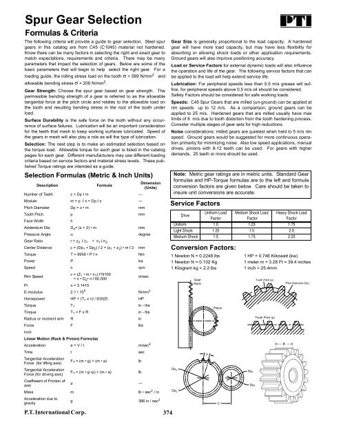
Spur Gear Selection<br />
Formulas & Criteria<br />
The following criteria will provide a guide to gear selection. Steel spur<br />
gears in this catalog are from C45 (C1045) material not hardened.<br />
Know there can be many factors in selecting the right and exact gear to<br />
match expectations, requirements and criteria. There may be many<br />
parameters that impact the selection of gears. Below are some of the<br />
basic parameters that will begin to help select the right gear. For a<br />
loading guide, the rolling stress load on the tooth σ = 589 N/mm 2 and<br />
allowable bending stress σ = 200 N/mm 2 .<br />
Gear Strength: Choose the spur gear based on gear strength. The<br />
permissible bending strength of a gear is referred to as the allowable<br />
tangential force at the pitch circle and relates to the allowable load on<br />
the tooth and resulting bending stress in the root of the tooth under<br />
load.<br />
Surface Durability is the safe force on the tooth without any occurrence<br />
of surface failures. Lubrication will be an important consideration<br />
for the teeth that mesh to keep working surfaces lubricated. Speed of<br />
the gears in mesh will also play a role as will the type of lubrication.<br />
Selection: The next step is to make an estimated selection based on<br />
the torque load. Allowable torque for each gear is listed in the catalog<br />
pages for each gear. Different manufacturers may use different loading<br />
criteria based on service factors and material stress levels. These published<br />
Torque ratings are intended as a guide.<br />
Selection Formulas (Metric & Inch Units)<br />
Description<br />
Formula<br />
Dimension<br />
(Units)<br />
Number of Teeth z = Dp / m —<br />
Module m = p / π = Dp / z —<br />
Pitch Diameter Dp = z • m mm<br />
Tooth Pitch p mm<br />
Face Width<br />
h<br />
Addendum Dia. D e = (z + 2) • m mm<br />
Pressure Angle α degree<br />
Gear Ratio r = z 2 / z 1 = n 1 / n 2<br />
Center Distance c = (Dp 1 + Dp 2 ) / 2 = (z 1 + z 2 ) • m / 2 mm<br />
Torque T = 9950 • P / n Nm<br />
Power P kw<br />
Speed n rpm<br />
Rim Speed<br />
v = (Z 1 • m • n 1 ) /19100<br />
= π • D e • n / 60,000<br />
m/sec<br />
Pi π = 3.1415<br />
E-modulus 2.1 • 10 5 N/mm 2<br />
Horsepower HP = (T 1 x n) / 63025 HP<br />
Torque T 1 in - lbs<br />
Troque T 1 = F x R in - lbs<br />
Radius or moment arm R in<br />
Force F lbs<br />
Inch<br />
Linear Motion (Rack & Pinion) Formulas<br />
Acceleration a = V / t m/sec 2<br />
Time t sec<br />
Tangential Acceleration<br />
Force (for lifting axis)<br />
F T = (m • g) + (m • a)<br />
lb<br />
Tangential Acceleration<br />
Force (for driving axis)<br />
F T = (m • g •µ) + (m • a)<br />
lb<br />
Coeffieient of Friction of<br />
axis<br />
µ —<br />
Mass m lb • sec 2 / in<br />
Acceleration due to<br />
gravity<br />
g 386 in / sec 2<br />
P.T. International Corp.<br />
374<br />
Gear Size is generally proportional to the load capacity. A hardened<br />
gear will have more load capacity, but may have less flexibility for<br />
absorbing or allowing shock loads or other application requirements.<br />
Ground gears will also improve positioning accuracy.<br />
Load or Service Factors for external dynamic loads will also influence<br />
the operation and life of the gear. The following service factors that can<br />
be applied to the load will help extend service life.<br />
Lubrication: For peripheral speeds less than 0.5 m/s grease will suffice,<br />
for peripheral speeds above 0.5 m/s oil should be considered.<br />
Safety Factors should be considered for safe working loads.<br />
Speeds: C45 Spur Gears that are milled (un-ground) can be applied at<br />
rim speeds up to 12 m/s. As a <strong>com</strong>parison, ground gears can be<br />
applied to 25 m/s. Hardened gears that are milled usually have max<br />
limits of 8 m/s due to tooth distortion from the tooth hardening process.<br />
Consider multiple stages of gear sets for high reductions.<br />
Noise considerations: milled gears are quietest when held to 5 m/s rim<br />
speed. Ground gears would be suggested for more continuous operation<br />
primarily for minimizing noise. Also low speed applications, manual<br />
drives, pinions with 8-12 teeth can be used. For gears with higher<br />
demands, 25 teeth or more should be used.<br />
Note: Metric gear ratings are in metric units. Standard Gear<br />
formulas and HP-Torque formulas are to the left and formula<br />
conversion factors are given below. Care should be taken to<br />
insure unit conversions are accurate.<br />
Service Factors<br />
Drive<br />
Uniform Load Medium Shock Load Heavy Shock Load<br />
Factor<br />
Factor<br />
Factor<br />
Uniform 1.0 1.25 1.75<br />
Light Shock 1.25 1.5 2.0<br />
Medium Shock 1.5 1.75 2.25<br />
Conversion Factors:<br />
1 Newton N = 0.2248 lbs<br />
1 Newton N = 0.102 Kg<br />
1 Kilogram kg = 2.2 lbs<br />
Dp 2<br />
De 2<br />
Gear<br />
Rack<br />
p<br />
Pinion<br />
C<br />
1 HP = 0.746 Kikowatt (kw)<br />
1 meter m = 3.28 Ft = 39.4 inches<br />
1 inch = 25.4mm<br />
Dp 1<br />
De 1<br />
Tooth Pitch (p)<br />
Tooth Pitch (p)<br />
Pitch Diameter (Dp)