Fleck Model 9000/9100/9500 - Pentair Residential Filtration
Fleck Model 9000/9100/9500 - Pentair Residential Filtration
Fleck Model 9000/9100/9500 - Pentair Residential Filtration

You also want an ePaper? Increase the reach of your titles
YUMPU automatically turns print PDFs into web optimized ePapers that Google loves.
INSTALLATION & START-UP<br />
Water Pressure<br />
A minimum of 25 pounds of water pressure is required for<br />
regeneration valve to operate effectively.<br />
Electrical Facilities<br />
A continuous 115 volt, 60 Hertz current supply is required.<br />
Make certain the current supply is always hot and cannot be<br />
turned off with another switch.<br />
Existing Plumbing<br />
Condition of existing plumbing should be free from lime and<br />
iron buildup. Piping that is built up heavily with lime and/or iron<br />
should be replaced. If piping is clogged with iron, a separate<br />
iron filter unit should be installed ahead of the water softener.<br />
Location Of Softener And Drain<br />
The softener should be located close to a drain.<br />
BY-PASS VALVES<br />
Always provide for the installation of a by-pass valve.<br />
CAUTION Water pressure is not to exceed 125 psi (8.6 bar),<br />
water temperature is not to exceed 110°F (43°C),<br />
and the unit cannot be subjected to freezing<br />
conditions.<br />
1. Place the softener tank where you want to install the unit.<br />
NOTE: Be sure the tank is level and on a firm base.<br />
2. During cold weather it is recommended that the installer<br />
warm the valve to room temperature before operating.<br />
3. Perform all plumbing according to local plumbing codes.<br />
• Use a 1/2" minimum pipe size for the drain.<br />
• Use a 3/4" drain line for backwash flow rates that<br />
exceed 7 gpm or length that exceeds 20' (6 m).<br />
14. Place the bypass In Service position and let water flow into<br />
the mineral tank. When water flow stops, slowly open a cold<br />
water tap nearby and let water run until air is purged from<br />
the unit. Then close tap.<br />
15. Make all electrical connections according to codes. Plug the<br />
valve into an approved power source. Do not insert meter<br />
cable into the meter yet.<br />
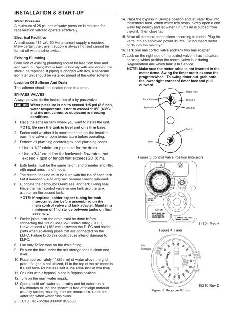
16. Tank one has control valve and tank two has adapter.<br />
17. Look on the right side of the control valve, it has indicators<br />
showing which position the control valve is in during<br />
Regeneration and which tank is In Service.<br />
NOTE: Make sure the meter cable is not inserted in the<br />
meter dome. Swing the timer out to expose the<br />
program wheel. To swing timer out, grab onto<br />
the lower right corner of timer face and pull<br />
outward.<br />
Figure 3 Control Valve Position Indicators<br />
4. Both tanks must be the same height and diameter and filled<br />
with equal amounts of media.<br />
5. The distributor tube must be flush with the top of each tank.<br />
Cut if necessary. Use only non-aerosol silicone lubricant.<br />
6. Lubricate the distributor O-ring seal and tank O-ring seal.<br />
Place the main control valve on one tank and the tank<br />
adapter on the second tank.<br />
NOTE: If required, solder copper tubing for tank<br />
interconnection before assembling on the<br />
main control valve and tank adapter. Maintain a<br />
minimum of 1" distance between tanks on final<br />
assembly.<br />
7. Solder joints near the drain must be done before<br />
connecting the Drain Line Flow Control fitting (DLFC).<br />
Leave at least 6" (152 mm) between the DLFC and solder<br />
joints when soldering pipes that are connected on the<br />
DLFC. Failure to do this could cause interior damage to<br />
DLFC.<br />
8. Use only Teflon tape on the drain fitting.<br />
9. Be sure the floor under the salt storage tank is clean and<br />
level.<br />
10. Place approximately 1" (25 mm) of water above the grid<br />
plate. If a grid is not utilized, fill to the top of the air check in<br />
the salt tank. Do not add salt to the brine tank at this time.<br />
11. On units with a bypass, place in Bypass position.<br />
12. Turn on the main water supply.<br />
13. Open a cold soft water tap nearby and let water run a<br />
few minutes or until the system is free of foreign material<br />
(usually solder) resulting from the installation. Close the<br />
water tap when water runs clean.<br />
2 • OC10 <strong>Fleck</strong> <strong>Model</strong> <strong>9000</strong>/<strong>9100</strong>/<strong>9500</strong><br />
Figure 4 Timer<br />
Figure 5 Program Wheel<br />
61591 Rev A<br />
19210 Rev D