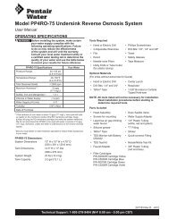
742/762 Control 255 and Performa Series Valves - Pentair ...
742/762 Control 255 and Performa Series Valves - Pentair ...
742/762 Control 255 and Performa Series Valves - Pentair ...

You also want an ePaper? Increase the reach of your titles
YUMPU automatically turns print PDFs into web optimized ePapers that Google loves.
<strong>742</strong>/<strong>762</strong> <strong>Control</strong><br />
<strong>255</strong> <strong>and</strong> <strong>Performa</strong> <strong>Series</strong> <strong>Valves</strong><br />
(263, 268, 268FA)<br />
Operation Manual<br />
For Sales & Service questions please contact<br />
your dealer:<br />
Your local dealer is:
TABLE OF CONTENTS<br />
LOGIX SERIES INSTALLER QUICK-START SHEET 3<br />
MANUAL OVERVIEW 8<br />
How To Use This Manual<br />
EQUIPMENT INSTALLATION 9<br />
General Warnings And Safety Information<br />
<strong>Performa</strong>nce Data Sheets<br />
Valve Features<br />
Location Selection<br />
Water Line Connection<br />
Drain Line Connection<br />
Overflow Line Connection<br />
Regenerant Line Connection<br />
Electrical Connection<br />
Valve Camshaft<br />
SYSTEM DISINFECTION 30<br />
Disinfection Of Water Conditioners<br />
DETERMINING IF YOU HAVE A <strong>742</strong> OR <strong>762</strong> CONTROL 32<br />
GENERAL 700 SERIES INSTRUCTIONS 33<br />
Display Icons 700 <strong>Control</strong>ler<br />
Keypad — Buttons<br />
Regeneration Modes<br />
<strong>742</strong>/<strong>762</strong> <strong>Series</strong> Initial Power-Up<br />
Initial Start-up Step-By-Step Instructions<br />
PLACING CONDITIONER INTO OPERATION (turning on the water) 42<br />
PROGRAMMING THE 700 FOR 5-CYCLE FILTER APPLICATIONS 45<br />
Manganese Greens<strong>and</strong> Systems<br />
<strong>742</strong>/<strong>762</strong> SERIES ADVANCED PROGRAMMING 48<br />
<strong>742</strong>/<strong>762</strong> Level II Professional Programming 49<br />
PARTS AND ACCESSORIES 52<br />
<strong>255</strong> Valve Exploded View<br />
<strong>255</strong> Valve Parts List<br />
<strong>Performa</strong> Exploded View<br />
<strong>Performa</strong> Parts List<br />
Logix 700 <strong>Series</strong> <strong>Control</strong>lers Parts List<br />
TROUBLESHOOTING 58<br />
2<br />
Rev J
LOGIX SERIES INSTALLER QUICK-START SHEET<br />
Logix <strong>Series</strong> <strong>Control</strong>lers<br />
See Determining If You Have a <strong>742</strong> or <strong>762</strong> <strong>Control</strong> on page 32 to identify your<br />
controller.<br />
Initial Power-up<br />
Time & Day<br />
Regen Time & Day<br />
Salt<br />
Capacity<br />
Hardness<br />
SU MO TU WE TH FR SA DAYS<br />
<strong>742</strong> <strong>Control</strong>ler - Electronic time clock control capable of doing 7-day (day of<br />
week) regeneration, or up to a 99 interval day regeneration. This control will<br />
operate both in a conditioner (softener) or 3-cycle filter mode with the same<br />
controller.<br />
<strong>762</strong> <strong>Control</strong>ler - Electronic metered-dem<strong>and</strong> (volumetric) controller which<br />
regenerates based on the water usage of the installation site. A calendar<br />
override is a st<strong>and</strong>ard feature on this controller.<br />
The Logix <strong>Series</strong> will operate on both the <strong>255</strong> <strong>and</strong> <strong>Performa</strong> valve body<br />
series.<br />
LCD Display<br />
DOWN Button<br />
Time & Day<br />
Regen Time & Day<br />
Salt<br />
x2<br />
Capacity<br />
P<br />
Hardness CH<br />
SET Button<br />
SU MO TU WE TH FR SA DAYS<br />
PM<br />
MIN<br />
LBS<br />
KG<br />
x100<br />
Manual Regeneration<br />
UP Button<br />
For 5-cycle filter applications, see page 45 for setting details.<br />
Initial Power Up - (CAMSHAFT proceeds to HOME position)<br />
• At initial power-up, the camshaft will need to rotate to the HOME<br />
(in service) position.<br />
• Camshaft may take 1-2 minutes to return to home position.<br />
• Err 3 will be displayed until the camshaft returns to home.<br />
• If more than 2 minutes elapses, verify that the motor is turning the camshaft.<br />
If it is not turning, see the troubleshooting section.<br />
QUICK START<br />
NOTE: The Logix controller features a self-test sequence. At first<br />
power-up of the control, you may see a number such as 1.00, 1.02,<br />
1.04, or 2.00 displayed. This is an indication that the self-test is not<br />
completed. To complete the test, verify that the turbine cable is<br />
connected. Blow into the turbine port (valve outlet) to spin the<br />
turbine. The controller will verify that the turbine works <strong>and</strong> the self<br />
test will finish. Proceed with the initial start up procedure.<br />
3<br />
Rev J
Initial Start-up Step-by-step Instructions<br />
Step 1: Select Valve Type<br />
This step may have been performed by your system’s OEM manufacturer. In<br />
this case, proceed to step 2.<br />
• Identify your valve body type by looking at the silver ID sticker on the back<br />
or side of the valve body.<br />
• Select your valve body type using the UP or DOWN buttons.<br />
• Display Valve Body<br />
<strong>255</strong> <strong>255</strong>, 7-cycle conditioner<br />
263 <strong>Performa</strong> filter 263, 3-cycle filter<br />
268 <strong>Performa</strong> conditioner 268, 7-cycle conditioner<br />
273 <strong>Performa</strong> Cv 273, 3-cycle filter<br />
278 <strong>Performa</strong> Cv 278, 5-cycle conditioner<br />
293 Magnum Cv filter, 3-cycle filter<br />
298 Magnum Cv conditioner, 7-cycle conditioner<br />
QUICK START<br />
SU MO TU WE TH FR SA DAYS<br />
Time & Day<br />
Regen Time & Day<br />
Salt<br />
Capacity<br />
Hardness<br />
SU MO TU WE TH FR SA DAYS<br />
Time & Day<br />
Regen Time & Day<br />
Salt<br />
Capacity<br />
Hardness<br />
SU MO TU WE TH FR SA DAYS<br />
Time & Day<br />
Capacity<br />
Hardness<br />
SU MO TU WE TH FR SA DAYS<br />
Time & Day<br />
Regen Time & Day<br />
Salt<br />
Capacity<br />
Hardness<br />
SU MO TU WE TH FR SA DAYS<br />
Time & Day<br />
Regen Time & Day<br />
Salt<br />
Capacity<br />
Hardness<br />
NOTE: Different <strong>742</strong>/<strong>762</strong> control hardware is necessary to operate<br />
the 150S valve body.<br />
Step 2: Program System Size<br />
This step may have been performed by your system’s OEM manufacturer. In<br />
this case, proceed to step 3.<br />
• Input system size - resin volume - in cubic feet or liters.<br />
• Use UP <strong>and</strong> DOWN buttons to scroll through resin volume choices.<br />
• Choose the nearest volume to your actual system size.<br />
• To choose a 3-cycle filter operation - press DOWN until an "F" is<br />
displayed.<br />
• Press SET to accept the system size you’ve selected.<br />
• If incorrect setting is programmed, see "Resetting the <strong>Control</strong>" section<br />
below.<br />
Step 3: Program Time of Day<br />
• While "12:00" is blinking, set the correct time of day.<br />
• Use the UP <strong>and</strong> DOWN buttons to scroll to the correct time of day.<br />
• "PM" is indicated, "AM" is not indicated.<br />
• Press SET to accept the correct time of day <strong>and</strong> advance to the next<br />
parameter.<br />
Step 4: Set Day of Week<br />
• Press SET to make the arrow under SU flash.<br />
• Use the UP <strong>and</strong> DOWN buttons to advance the arrow until it is under the<br />
correct day of week.<br />
• Press SET to accept <strong>and</strong> advance to the next parameter.<br />
Step 5: Set Regen Time<br />
• 2:00 (AM) is the default time of regeneration. To accept this time, press<br />
the DOWN button to move to step 6.<br />
• To change the regen time, press SET - causing 2:00 to flash.<br />
• Use the UP <strong>and</strong> DOWN buttons to advance to the desired regen time.<br />
• Press SET to accept the time <strong>and</strong> advance to the next parameter.<br />
4<br />
Rev J
Step 6: Set Days to Regenerate (<strong>742</strong> Time-clock <strong>Control</strong> Only)<br />
• If using <strong>762</strong> control - proceed to step 6a.<br />
SU MO TU WE TH FR SA DAYS<br />
Time & Day<br />
• Set number of days between time-clock regeneration (regen frequency).<br />
Regen Time & Day<br />
Salt<br />
• Default time is 3 days.<br />
• Days can be adjusted from 1/2 (.5) to 99 days.<br />
Capacity<br />
Hardness<br />
• To change, press SET to make the "3" flash.<br />
• Use the UP <strong>and</strong> DOWN buttons to change to the number of days desired.<br />
• Press SET to accept the regen frequency, <strong>and</strong> advance to the next cycle.<br />
SU MO TU<br />
Time & Day<br />
WE TH FR SA DAYS<br />
To use the 7-day timer option - see full Dealer Installation Manual.<br />
Step 6a: Set Calendar Override (<strong>762</strong> Dem<strong>and</strong> <strong>Control</strong> Only)<br />
Regen Time & Day<br />
Salt<br />
• If using <strong>742</strong> control - proceed to step 7.<br />
• Set number of days for calendar override on dem<strong>and</strong> control.<br />
Capacity<br />
Hardness<br />
• "0" days is the default for calendar override.<br />
• Days can be adjusted from 1/2 (.5) to 99 days.<br />
SU MO TU WE TH FR SA DAYS<br />
Time & Day<br />
• To change, press SET to make the "0" flash.<br />
Regen Time & Day<br />
Backwash Time<br />
• Use the UP or DOWN buttons to change to the number of days desired.<br />
• Press SET to accept the regen frequency, <strong>and</strong> advance to the next cycle.<br />
Capacity<br />
Hardness<br />
Step 7: Set Salt Amount (Regenerant Amount)<br />
• Default setting is "9 pounds per ft 3 (110 g/L)".<br />
• Use UP or DOWN to select regenerant amount.<br />
• Press SET to accept the setting <strong>and</strong> advance to next parameter.<br />
See page 39 for more complete information on regenerant settings for<br />
different system sizes, capacities <strong>and</strong> expected efficiencies.<br />
Step 8: Estimated Capacity<br />
• System capacity is displayed in total kilograins or kilograms of hardness<br />
SU MO TU WE TH FR SA DAYS<br />
Time & Day<br />
removed before a regeneration is necessary.<br />
Regen Time & Day<br />
Salt<br />
• Value is derived from the system’s resin volume input, <strong>and</strong> salt amount<br />
KG input.<br />
Capacity<br />
Hardness<br />
• The capacity displayed is a suggested value - as recommended by resin<br />
manufacturers.<br />
• Capacity is only displayed for information purposes on <strong>742</strong> control - it<br />
does not (<strong>and</strong> cannot) need to be changed.<br />
• To change capacity on <strong>762</strong> control, press SET to make the default<br />
capacity flash. Use the UP <strong>and</strong> DOWN buttons to increment to the<br />
desired capacity.<br />
• Press SET to accept the setting <strong>and</strong> advance to the next parameter.<br />
If using <strong>742</strong> control, programming is complete. The control will return you to the normal operation<br />
mode.<br />
QUICK START<br />
5<br />
Rev J
Step 9: Enter Hardness (<strong>762</strong> Dem<strong>and</strong> <strong>Control</strong> Only)<br />
• Enter inlet water hardness at installation site.<br />
• Default hardness setting is 25 grains (25 ppm for metric)<br />
• To change hardness, press SET to make the setting flash. Use the UP<br />
<strong>and</strong> DOWN buttons to scroll to the correct hardness.<br />
• Press SET to accept the entered hardness value.<br />
• The control will return you to the normal operation mode.<br />
Initial system programming is now complete. The control will return to normal<br />
operation mode, if a button is not pushed for 30 seconds.<br />
For system start-up procedure, including: purging the mineral tank, refilling the regenerant tank, <strong>and</strong><br />
drawing regenerant, see Initial Startup Step-By-Step Instructions on page 37.<br />
QUICK START<br />
Manual Regeneration Procedures<br />
Second Manual Regen Symbol<br />
Time & Day<br />
Regen Time & Day<br />
Salt<br />
Capacity<br />
Hardness<br />
SU MO TU WE TH FR SA DAYS<br />
C<br />
Regen Symbol<br />
x2<br />
MIN<br />
Cycle Indicator<br />
To Initiate a Manual Regeneration:<br />
• Press REGEN once for delayed regeneration.<br />
System will regenerate at next set regen time (2:00 AM).<br />
A flashing regen (recycle) symbol will be displayed.<br />
• Press <strong>and</strong> hold REGEN for 5 seconds to initiate immediate manual<br />
regeneration. A solid regen symbol will be displayed.<br />
• After immediate regeneration has begun, press REGEN again to initiate a<br />
second manual regeneration. An X2 symbol will be displayed, indicating a<br />
second regeneration will follow the first regeneration.<br />
During a Regeneration:<br />
• A "C#" is displayed to show current cycle.<br />
• Total regen time remaining is displayed on screen.<br />
• Press <strong>and</strong> hold SET to show current cycle time remaining.<br />
To Advance Regeneration Cycles:<br />
• Press <strong>and</strong> hold SET - showing current cycle time.<br />
• Simultaneously press SET <strong>and</strong> UP to advance one cycle.<br />
An hourglass will display while cam is advancing.<br />
When cam reaches next cycle, "C2" will be displayed.<br />
• Repeat SET <strong>and</strong> UP to advance through each cycle.<br />
• Press <strong>and</strong> hold SET <strong>and</strong> UP buttons for 5 seconds to cancel regen.<br />
Hourglass will begin flashing, indicating regen is cancelled.<br />
Camshaft will advance to home - may take 1-2 minutes.<br />
Regeneration Cycles:<br />
• C1 - Backwash<br />
• C2 - Regenerant Draw/Slow Rinse (not used in filter mode)<br />
• C3 - Slow Rinse (not used in filter mode)<br />
• C4 - System Pause (to repressurize tank)<br />
• C5 - Fast rinse cycle 1<br />
• C6 - Backwash cycle 2 (not used in filter mode)<br />
• C7 - Fast Rinse cycle 2 (not used in filter mode)<br />
• C8 - Regenerant refill (not used in filter mode)<br />
6<br />
Rev J
Resetting The <strong>Control</strong><br />
SU MO TU WE TH FR SA DAYS<br />
Time & Day<br />
Regen Time & Day<br />
Salt<br />
Capacity<br />
Hardness H<br />
Resetting the Logix <strong>Control</strong>ler<br />
SU MO TU WE TH FR SA DAYS<br />
Time & Day<br />
Regen Time & Day<br />
Salt<br />
Capacity<br />
Hardness<br />
Unprogrammed control after reset<br />
To reset the control:<br />
1. Press <strong>and</strong> hold SET <strong>and</strong> DOWN simultaneously for 5 seconds.<br />
2. H0 <strong>and</strong> the system’s set resin volume (or "F" mode) will be displayed.<br />
3. If a history value other than "H0" is displayed, use the up arrow to scroll<br />
through the settings until "H0" is displayed.<br />
4. To reset the control, press <strong>and</strong> hold SET for 5 seconds.<br />
5. The control will be reset to an unprogrammed state.<br />
6. Go to "Initial Set-up" section of this sheet to reprogram control.<br />
WARNING: Resetting the control will delete all information stored in<br />
its memory. This will require you to reprogram the control completely<br />
from the initial power up mode.<br />
Further programming or set-up instructions can be found in this manual.<br />
QUICK START<br />
7<br />
Rev J
MANUAL OVERVIEW<br />
How To Use This Manual<br />
Left Side<br />
Right Side<br />
This installation manual is designed to guide the installer through the process<br />
of installing <strong>and</strong> starting conditioners featuring the 700 Logix series<br />
controllers.<br />
This manual is a reference <strong>and</strong> will not include every system installation<br />
situation. The person installing this equipment should have:<br />
• Training in the 700 Logix series controllers <strong>and</strong> water conditioner<br />
installation<br />
• Knowledge of water conditioning <strong>and</strong> how to determine proper control<br />
settings<br />
• Basic plumbing skills<br />
• The directional instructions "left" <strong>and</strong> “right" are determined by looking at<br />
the front of the unit.<br />
Icons That Appear In This Manual<br />
WARNING: Failure to follow this instruction can result in personal injury or<br />
damage to the equipment.<br />
NOTE: This will make the process easier if followed.<br />
8 How To Use This Manual<br />
Rev J
EQUIPMENT INSTALLATION<br />
General Warnings And Safety Information<br />
UNDER<br />
TESTED AND CERTIFIED<br />
INDUSTRY<br />
STANDARDS<br />
The systems below have been Tested <strong>and</strong> Certified by WQA to<br />
NSF/ANSI Std. 44 <strong>and</strong> NSF/ANSI 372 for “Lead Free”<br />
compliance.<br />
The <strong>255</strong> valve <strong>and</strong> 268 valve have been Tested <strong>and</strong> Certified by<br />
WQA to NSF/ANSI Std 61 Section 8 Mechanical Devices.<br />
WQA Certified <strong>255</strong> Valve Systems<br />
WQA Certified 268 Valve Systems<br />
<strong>255</strong>-<strong>742</strong>-075-844 268-<strong>742</strong>-948<br />
<strong>255</strong>-<strong>742</strong>-100-948 268-<strong>742</strong>-150-1054<br />
<strong>255</strong>-<strong>742</strong>-100-1040 268-<strong>742</strong>-200-1248<br />
<strong>255</strong>-<strong>742</strong>-150-1054 268-<strong>762</strong>-948<br />
<strong>255</strong>-<strong>762</strong>-075-844 268-<strong>762</strong>-150-1054<br />
<strong>255</strong>-<strong>762</strong>-100-948 268-768-200-1248<br />
<strong>255</strong>-<strong>762</strong>-100-1040<br />
<strong>255</strong>-<strong>762</strong>-150-1054<br />
General Warnings And Safety Information 9<br />
Rev J
WATER SOFTENER PERFORMANCE DATA SHEET<br />
Model <strong>255</strong>-<strong>742</strong>-075-844 <strong>255</strong>-<strong>742</strong>-100-948 <strong>255</strong>-<strong>742</strong>-100-1040 <strong>255</strong>-<strong>742</strong>-150-1054<br />
Rated Service Flow (gpm) 6.0 10.0 11.0 10.4<br />
Pressure Drop at Rated Service<br />
Flow Rate (psi)<br />
8.0 15.0 14.0 15.0<br />
Rated Capacity<br />
(grains @ lbs. of salt)<br />
10, 719 @ 2.65<br />
22,110 @ 6.75<br />
25,503 @ 11.25<br />
14,293 @ 3.5<br />
29,480 @ 9.0<br />
34,004 @ 15.0<br />
12,163 @ 3.5<br />
25,087 @ 9.0<br />
28,937 @ 15.0<br />
21,439 @ 5.25<br />
44,220 @ 13.5<br />
51,006 @ 22.5<br />
Rated Efficiency<br />
(grains/lb Salt @ lb. of salt)<br />
4,083/lb. salt @ 2.65 lbs. 4,083/lb. salt @ 3.5 lbs. 3,475/lb. salt @ 3.5 lbs. 4,083/lb. salt @ 5.25 lbs.<br />
Maximum Flow Rate During<br />
Regeneration (gpm)<br />
Sybron C-249NS<br />
Ion Exchange Resin (cu ft)<br />
1.7 2.1 2.7 2.7<br />
0.75 1.0 1.0 1.5<br />
Backwash - GPM 1.7 2.1 2.7 2.7<br />
Rapid Rinse/purge - GPM<br />
1.7 2.1 2.7 2.7<br />
Operating Pressure: 20 -125 psi or 1.4 – 8.8 kg/Centimeter 2 , Operating Temperature: 34 - 100° F or 1.1 – 38° C<br />
Acceptable Salt Type: Sodium Chloride – Pellet or solar salt for water softeners<br />
All Systems above tested at 35psi +/- 5 psi, pH of 7.5 +/- 0.5, Capacity Testing Flow Rate = 50% of the rated service flow rate for the various size systems.<br />
These water softener systems have been tested by WQA <strong>and</strong> conform to NSF/ANSI 44 for specific performance claims as verified <strong>and</strong> substantiated by test data. The rated salt efficiencies above<br />
were also determined in accordance with NSF/ANSI 44 <strong>and</strong> are only valid at the salt dosage referenced above. An efficiency rated water softener is a dem<strong>and</strong> initiated regeneration (DIR) softener<br />
which also complies with specific performance specifications intended to minimize the amount of regenerant brine <strong>and</strong> water used in its operation. Efficiency rated water softeners shall have a rated<br />
salt efficiency of not less that 3350 grains of total hardness exchanged per pound of salt (based on NaCl equivalency) (477 grams of total hardness exchanged per kilogram of salt), <strong>and</strong> shall not<br />
deliver more salt than its listed rating. The rated efficiency of the water softener, the salt dosage at that efficiency, the capacity at that salt dosage <strong>and</strong> that of the efficiency is only valid at the stated salt<br />
dosage. Efficiency is measured by a laboratory test described in NSF/ANSI 44. The test represents the maximum possible efficiency the system can achieve. Operational efficiency is the actual<br />
efficiency achieved after the system has been installed. It is typically less than the efficiency due to individual application factors including water hardness, water usage, <strong>and</strong> other contaminants that<br />
reduce the water softener’s capacity. These systems are not intended to be used for treating water that is microbiologically unsafe or of unknown quality without adequate disinfection before or after<br />
the system. Refer to the system Installation <strong>and</strong> Service Manuals for set-up <strong>and</strong> programming instructions.<br />
Contact your local Autotrol dealer for parts <strong>and</strong> service. See your owner’s manual for warranty information.<br />
Important Notice: For conditions of use, health claims certified by the California Department of Public Health <strong>and</strong> replacement parts, see product data sheet<br />
Iowa Requirement:<br />
Seller: ______________________________________________________________ Date: _________________________<br />
Tested <strong>and</strong> Certified by<br />
WQA against NSF/ANSI<br />
St<strong>and</strong>ard 44 & NSF/ANSI 372<br />
for “lead free” compliance.<br />
Buyer: ______________________________________________________________ Date: _________________________ The valve used on this unit is<br />
Tested <strong>and</strong> Certified by WQA<br />
to NSF/ANSI Std. 61 Section 8<br />
for Material Safety Only<br />
PENTAIR Residential Filtration, LLC<br />
5730 North Glen Park Road Milwaukee, Wisconsin 53209<br />
PHONE: (262)-238-4400<br />
<strong>Pentair</strong> Residential Filtration, LLC 3/2/11<br />
10 General Warnings And Safety Information<br />
Rev J
WATER SOFTENER PERFORMANCE DATA SHEET<br />
Model <strong>255</strong>-<strong>762</strong>-075-844 <strong>255</strong>-<strong>762</strong>-100-948 <strong>255</strong>-<strong>762</strong>-100-1040 <strong>255</strong>-<strong>762</strong>-150-1054<br />
Rated Service Flow (gpm) 6.0 10.1 10.7 10.0<br />
Pressure Drop at Rated Service<br />
Flow Rate (psi)<br />
8.0 15.0 13.0 14.0<br />
Rated Capacity<br />
(grains @ lbs. of salt)<br />
10, 719 @ 2.65<br />
22,110 @ 6.75<br />
25,503 @ 11.25<br />
14,293 @ 3.5<br />
29,480 @ 9.0<br />
34,004 @ 15.0<br />
12,163 @ 3.5<br />
25,087 @ 9.0<br />
28,937 @ 15.0<br />
21,439 @ 5.25<br />
44,220 @ 13.5<br />
51,006 @ 22.5<br />
Rated Efficiency<br />
(grains/lb Salt @ lb. of salt)<br />
4,083/lb. salt @ 2.65 lbs. 4,083/lb. salt @ 3.5 lbs. 3,475/lb. salt @ 3.5 lbs. 4,083/lb. salt @ 5.25 lbs.<br />
Maximum Flow Rate During<br />
Regeneration (gpm)<br />
Sybron C-249NS<br />
Ion Exchange Resin (cu ft)<br />
1.7 2.1 2.7 2.7<br />
0.75 1.0 1.0 1.5<br />
Backwash - GPM 1.7 2.1 2.7 2.7<br />
Rapid Rinse/purge - GPM<br />
1.7 2.1 2.7 2.7<br />
Operating Pressure: 20 -125 psi or 1.4 – 8.8 kg/Centimeter 2 , Operating Temperature: 34 - 100° F or 1.1 – 38° C<br />
Acceptable Salt Type: Sodium Chloride – Pellet or solar salt for water softeners<br />
All Systems above tested at 35psi +/- 5 psi, pH of 7.5 +/- 0.5, Capacity Testing Flow Rate = 50% of the rated service flow rate for the various size systems.<br />
These water softener systems have been tested by WQA <strong>and</strong> conform to NSF/ANSI 44 for specific performance claims as verified <strong>and</strong> substantiated by test data. The rated salt efficiencies above<br />
were also determined in accordance with NSF/ANSI 44 <strong>and</strong> are only valid at the salt dosage referenced above. An efficiency rated water softener is a dem<strong>and</strong> initiated regeneration (DIR) softener<br />
which also complies with specific performance specifications intended to minimize the amount of regenerant brine <strong>and</strong> water used in its operation. Efficiency rated water softeners shall have a rated<br />
salt efficiency of not less that 3350 grains of total hardness exchanged per pound of salt (based on NaCl equivalency) (477 grams of total hardness exchanged per kilogram of salt), <strong>and</strong> shall not<br />
deliver more salt than its listed rating. The rated efficiency of the water softener, the salt dosage at that efficiency, the capacity at that salt dosage <strong>and</strong> that of the efficiency is only valid at the stated salt<br />
dosage. Efficiency is measured by a laboratory test described in NSF/ANSI 44. The test represents the maximum possible efficiency the system can achieve. Operational efficiency is the actual<br />
efficiency achieved after the system has been installed. It is typically less than the efficiency due to individual application factors including water hardness, water usage, <strong>and</strong> other contaminants that<br />
reduce the water softener’s capacity. These systems are not intended to be used for treating water that is microbiologically unsafe or of unknown quality without adequate disinfection before or after<br />
the system. Refer to the system Installation <strong>and</strong> Service Manuals for set-up <strong>and</strong> programming instructions.<br />
Contact your local Autotrol dealer for parts <strong>and</strong> service. See your owner’s manual for warranty information.<br />
Important Notice: For conditions of use, health claims certified by the California Department of Public Health <strong>and</strong> replacement parts, see product data sheet<br />
Iowa Requirement:<br />
Seller: ______________________________________________________________ Date: _________________________<br />
Tested <strong>and</strong> Certified by<br />
WQA against NSF/ANSI<br />
St<strong>and</strong>ard 44 & NSF/ANSI 372<br />
for “lead free” compliance.<br />
Buyer: ______________________________________________________________ Date: _________________________ The valve used on this unit is<br />
Tested <strong>and</strong> Certified by WQA<br />
to NSF/ANSI Std. 61 Section 8<br />
for Material Safety Only<br />
PENTAIR Residential Filtration, LLC<br />
5730 North Glen Park Road Milwaukee, Wisconsin 53209<br />
PHONE: (262)-238-4400<br />
<strong>Pentair</strong> Residential Filtration, LLC 3/2/11<br />
General Warnings And Safety Information 11<br />
Rev J
268-<strong>742</strong> Valve <strong>Series</strong> Water Softener System <strong>Performa</strong>nce Data Sheet<br />
Model 268-<strong>742</strong>-100-948 268-<strong>742</strong>-150-1054 268-<strong>742</strong>-200-1248<br />
Rated Service Flow (gpm) 11.0 12.7 15.0<br />
Pressure Drop at Rated<br />
Service Flow Rate (psi)<br />
Rated Capacity<br />
(grains @ lb of salt)<br />
Rated Efficiency<br />
(grains/lb Salt @ lb of salt)<br />
Maximum Flow Rate During<br />
Regeneration (gpm)<br />
Sybron C-249NS<br />
Ion Exchange Resin (cu ft)<br />
12.9<br />
14,038 @ 3.3<br />
27,770 @ 9.0<br />
33,418 @ 15.0<br />
15.4 14.4<br />
21,411 @ 4.95<br />
42,354 @ 13.5<br />
50,968 @ 15.0<br />
28,548 @ 6.6<br />
56,472 @ 18.0<br />
67,958 @ 30.0<br />
4,252 /lb. salt @ 3.3 lbs. 4,325/lb. salt @ 4.95 lbs. 4,325/lb. salt @ 6.6 lbs.<br />
5.5<br />
1.0<br />
5.5 5.5<br />
1.5 2.0<br />
Tank Size 9 x 48 10 x 54 12 x 48<br />
Backwash - GPM 2.1<br />
2.7 3.9<br />
Rapid Rinse/purge - GPM<br />
5.5 5.5 5.5<br />
Operating Pressure:20 -125 psi or 1.4 – 8.8 kg/Centimeter 2 , Operating Temperature: 34 - 100° F or 1.1 – 38° C<br />
Acceptable Salt Type: Sodium Chloride – Pellet or solar salt for water softeners<br />
All Systems above tested at 35psi +/- 5 psi, pH of 7.5 +/- 0.5, Capacity Testing Flow Rate = 50% of the rated service flow rate for the various size systems.<br />
These water softener systems have been tested by WQA <strong>and</strong> conform to NSF/ANSI 44 for specific performance claims as verified <strong>and</strong> substantiated by<br />
test data. The rated salt efficiencies above were also determined in accordance with NSF/ANSI 44 <strong>and</strong> are only valid at the salt dosage referenced above.<br />
An efficiency rated water softener is a dem<strong>and</strong> initiated regeneration (DIR) softener which also complies with specific performance specifications intended<br />
to minimize the amount of regenerant brine <strong>and</strong> water used in its operation. Efficiency rated water softeners shall have a rated salt efficiency of not less<br />
that 3350 grains of total hardness exchanged per pound of salt (based on NaCl equivalency) (477 grams of total hardness exchanged per kilogram of salt),<br />
<strong>and</strong> shall not deliver more salt than its listed rating. The rated efficiency of the water softener, the salt dosage at that efficiency, the capacity at that salt<br />
dosage <strong>and</strong> that of the efficiency is only valid at the stated salt dosage. Efficiency is measured by a laboratory test described in NSF/ANSI 44. The test<br />
represents the maximum possible efficiency the system can achieve. Operational efficiency is the actual efficiency achieved after the system has been<br />
installed. It is typically less than the efficiency due to individual application factors including water hardness, water usage, <strong>and</strong> other contaminants that<br />
reduce the water softener’s capacity. These systems are not intended to be used for treating water that is microbiologically unsafe or of unknown quality<br />
without adequate disinfection before or after the system. Refer to the system Installation <strong>and</strong> Service Manuals for set-up <strong>and</strong> programming instructions.<br />
Contact your local dealer for parts <strong>and</strong> service. See your owner’s manual for warranty information.<br />
Important Notice: For conditions of use, health claims certified by the California Department of Public Health <strong>and</strong> replacement parts, see product data sheet<br />
Iowa Requirement:<br />
Tested <strong>and</strong> Certified by WQA against NSF/ANSI<br />
Std. 44 & 372 for “lead free” compliance.<br />
Seller: ______________________________________________________________ Date: _________________________<br />
Buyer: ______________________________________________________________ Date: _________________________<br />
7/16/10<br />
The valve used on this unit is Tested <strong>and</strong> Certified<br />
by WQA to NSF/ANSI Std. 61 Section 8 for<br />
Material Safety Only<br />
PENTAIR Residential Filtration, LLC<br />
5730 North Glen Park Road<br />
Milwaukee, Wisconsin 53209<br />
PHONE: (262)-238-4400<br />
12 General Warnings And Safety Information<br />
Rev J
268-<strong>762</strong> Valve <strong>Series</strong> Water Softener System <strong>Performa</strong>nce Data Sheet<br />
Model 268-<strong>762</strong>-100-948 268-<strong>762</strong>-150-1054 268-<strong>762</strong>-200-1248<br />
Rated Service Flow (gpm) 11.0 12.7 15.0<br />
Pressure Drop at Rated<br />
Service Flow Rate (psi)<br />
Rated Capacity<br />
(grains @ lb of salt)<br />
Rated Efficiency<br />
(grains/lb Salt @ lb of salt)<br />
Maximum Flow Rate During<br />
Regeneration (gpm)<br />
Sybron C-249NS<br />
Ion Exchange Resin (cu ft)<br />
12.9<br />
14,038 @ 3.3<br />
27,770 @ 9.0<br />
33,418 @ 15.0<br />
15.4 14.4<br />
21,411 @ 4.95<br />
42,354 @ 13.5<br />
50,968 @ 15.0<br />
28,548 @ 6.6<br />
56,472 @ 18.0<br />
67,958 @ 30.0<br />
4,252 /lb. salt @ 3.3 lbs. 4,325/lb. salt @ 4.95 lbs. 4,325/lb. salt @ 6.6 lbs.<br />
5.5<br />
1.0<br />
5.5 5.5<br />
1.5 2.0<br />
Tank Size 9 x 48 10 x 54 112 x 48<br />
Backwash - GPM 2.1 2.7 3.9<br />
Rapid Rinse/purge - GPM<br />
5.5 5.5 5.5<br />
Operating Pressure:20 -125 psi or 1.4 – 8.8 kg/Centimeter 2 , Operating Temperature: 34 - 100° F or 1.1 – 38° C<br />
Acceptable Salt Type: Sodium Chloride – Pellet or solar salt for water softeners<br />
All Systems above tested at 35psi +/- 5 psi, pH of 7.5 +/- 0.5, Capacity Testing Flow Rate = 50% of the rated service flow rate for the various size systems.<br />
These water softener systems have been tested by WQA <strong>and</strong> conform to NSF/ANSI 44 for specific performance claims as verified <strong>and</strong> substantiated by<br />
test data. The rated salt efficiencies above were also determined in accordance with NSF/ANSI 44 <strong>and</strong> are only valid at the salt dosage referenced above.<br />
An efficiency rated water softener is a dem<strong>and</strong> initiated regeneration (DIR) softener which also complies with specific performance specifications intended<br />
to minimize the amount of regenerant brine <strong>and</strong> water used in its operation. Efficiency rated water softeners shall have a rated salt efficiency of not less<br />
that 3350 grains of total hardness exchanged per pound of salt (based on NaCl equivalency) (477 grams of total hardness exchanged per kilogram of salt),<br />
<strong>and</strong> shall not deliver more salt than its listed rating. The rated efficiency of the water softener, the salt dosage at that efficiency, the capacity at that salt<br />
dosage <strong>and</strong> that of the efficiency is only valid at the stated salt dosage. Efficiency is measured by a laboratory test described in NSF/ANSI 44. The test<br />
represents the maximum possible efficiency the system can achieve. Operational efficiency is the actual efficiency achieved after the system has been<br />
installed. It is typically less than the efficiency due to individual application factors including water hardness, water usage, <strong>and</strong> other contaminants that<br />
reduce the water softener’s capacity. These systems are not intended to be used for treating water that is microbiologically unsafe or of unknown quality<br />
without adequate disinfection before or after the system. Refer to the system Installation <strong>and</strong> Service Manuals for set-up <strong>and</strong> programming instructions.<br />
Contact your local dealer for parts <strong>and</strong> service. See your owner’s manual for warranty information.<br />
Important Notice: For conditions of use, health claims certified by the California Department of Public Health <strong>and</strong> replacement parts, see product data sheet<br />
Iowa Requirement:<br />
Tested <strong>and</strong> Certified by WQA against NSF/ANSI<br />
Std. 44 & 372 for “lead free” compliance.<br />
Seller: ______________________________________________________________ Date: _________________________<br />
Buyer: ______________________________________________________________ Date: _________________________<br />
7/16/10<br />
The valve used on this unit is Tested <strong>and</strong> Certified<br />
by WQA to NSF/ANSI Std. 61 Section 8 for<br />
Material Safety Only<br />
PENTAIR Residential Filtration, LLC<br />
5730 North Glen Park Road<br />
Milwaukee, Wisconsin 53209<br />
PHONE: (262)-238-4400<br />
General Warnings And Safety Information 13<br />
Rev J
Electrical<br />
Mechanical<br />
There are no user-serviceable parts in the AC adapter, motor, or controller. In<br />
the event of a failure, these should be replaced.<br />
• All electrical connections must be completed according to local codes.<br />
• Use only the power AC adapter that is supplied.<br />
• The power outlet must be grounded.<br />
• To disconnect power, unplug the AC adapter from its power source.<br />
• Do not use petroleum based lubricants such as vaseline, oils, or<br />
hydrocarbon based lubricants. Use only 100% silicone lubricants.<br />
• All plastic connections should be h<strong>and</strong> tightened. Teflon tape may be<br />
used on connections that do not use an O-ring seal. Do not use pliers or<br />
pipe wrenches.<br />
• All plumbing must be completed according to local codes.<br />
• Soldering near the drain line should be done before connecting the drain<br />
line to the valve. Excessive heat will cause interior damage to the valve.<br />
• Observe drain line requirements.<br />
• Do not use lead-based solder for sweat solder connections.<br />
• The drain line must be a minimum of 1/2-inch diameter. Use<br />
3/4-inch pipe if the backwash flow rate is greater than 5 gpm<br />
(18.9 Lpm) or the pipe length is greater than 20 feet (6 m).<br />
• Do not support the weight of the system on the control valve fittings,<br />
plumbing, or the bypass.<br />
• It is not recommended to use sealants on the threads. Use Teflon* tape<br />
on the threads of the 1-inch NPT elbow, the drain line connections, <strong>and</strong><br />
other NPT threads.<br />
*Teflon is a trademark of E.I. duPont de Nemours.<br />
General<br />
• Observe all warnings that appear in this manual.<br />
• Keep the media tank in the upright position. Do not turn on side, upside<br />
down, or drop. Turning the tank upside down will cause media to enter the<br />
valve.<br />
• Operating ambient temperature is between 34F (1C) <strong>and</strong> 120F (49C).<br />
• Operating water temperature is between 34F (1F) <strong>and</strong> 100F (38C).<br />
• Working water pressure range is 20 to 125 psi (1.38 to 8.61 bar). In<br />
Canada the acceptable working water pressure range is 20 to 100 psi<br />
(1.38 to 6.89 bar).<br />
• Use only regenerant salts designed for water softening. Do not use ice<br />
melting, block, or rock salts.<br />
• Follow state <strong>and</strong> local codes for water testing. Do not use water that is<br />
micro biologically unsafe or of unknown quality.<br />
• When filling media tank, do not open water valve completely. Fill tank<br />
slowly to prevent media from exiting the tank.<br />
• When installing the water connection (bypass or manifold) connect to the<br />
plumbing system first. Allow heated parts to cool <strong>and</strong> cemented parts to<br />
set before installing any plastic parts. Do not get primer or solvent on O-<br />
rings, nuts, or the valve.<br />
14 General Warnings And Safety Information<br />
Rev J
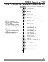
System Regeneration Cycles (7-Cycle Operation)<br />
1. Service (Downflow) — Cycle C0:<br />
Untreated water is directed down through the resin bed <strong>and</strong> up through<br />
the riser tube. The hardness ions attach themselves to the resin <strong>and</strong> are<br />
removed from the water. The water is conditioned as it passes through<br />
the resin bed.<br />
2. Backwash (Upflow) — Cycles C1, C6:<br />
The flow of water is reversed by the control valve <strong>and</strong> directed down the<br />
riser tube <strong>and</strong> up through the resin bed. During the backwash cycle, the<br />
bed is exp<strong>and</strong>ed <strong>and</strong> debris is flushed to the drain.<br />
3. Brine/Slow Rinse (Downflow) — Cycles C2, C3:<br />
The control directs water through the brine injector <strong>and</strong> brine is drawn<br />
from the regenerant tank. The brine is then directed down through the<br />
resin bed <strong>and</strong> up through the riser tube to the drain. The hardness ions<br />
are displaced by sodium ions <strong>and</strong> are sent to the drain. The resin is<br />
regenerated during the brine cycle. Brine draw is completed when the air<br />
check closes.<br />
4. Repressurize Cycle (Hard Water Bypass Flapper Open) — Cycle C4:<br />
This cycle allows the air <strong>and</strong> water to hydraulically balance in the valve<br />
before continuing the regeneration.<br />
5. Fast Rinse (Downflow) — Cycles C5, C7:<br />
The control directs water down through the resin bed <strong>and</strong> up through the<br />
riser tube to the drain. Any remaining brine residual is rinsed from the<br />
resin bed.<br />
6. Brine Refill — Cycle C8:<br />
Brine refill occurs during a portion of the fast rinse cycle. Water is directed<br />
to the regenerant tank at a controlled rate, to create brine for the next<br />
regeneration.<br />
General Warnings And Safety Information 15<br />
Rev J
Figure 1<br />
From Regenerant<br />
Tank<br />
SERVICE BACKWASH BRINE/SLOW RINSE<br />
C0 C1 <strong>and</strong> C6 C2 <strong>and</strong> C3<br />
To Regenerant<br />
Tank<br />
REPRESSURIZE<br />
FAST RINSE<br />
BRINE REFILL<br />
C4 C5 <strong>and</strong> C7 C8<br />
16 General Warnings And Safety Information<br />
Rev J
Valve Features<br />
Figure 2<br />
<strong>255</strong> Valve Identification<br />
<strong>Control</strong> Module<br />
Mount<br />
One Piece Valve<br />
Disc Spring<br />
Refill <strong>Control</strong>ler<br />
Right Side<br />
Injector <strong>and</strong> Cap<br />
Check Ball<br />
Manifold<br />
Air Check<br />
Connection<br />
Regenerant Tank<br />
Tube Connection<br />
Optical Sensor<br />
Valve Discs<br />
Camshaft<br />
Motor<br />
Left Side<br />
Outlet<br />
Drain<br />
Inlet<br />
Locking Bar<br />
Injector<br />
Screen Filter<br />
Backwash<br />
Drain <strong>Control</strong><br />
Valve Features 17<br />
Rev J
Figure 3<br />
<strong>Performa</strong> Valve Identification<br />
Valve Discs<br />
One Piece Valve<br />
Disc Spring<br />
<strong>Control</strong> Module<br />
Mount<br />
Right Side<br />
Refill <strong>Control</strong>ler<br />
Injector <strong>and</strong> cap<br />
Regenerant Tube Connection<br />
Optical Sensor<br />
Camshaft<br />
Motor<br />
Left Side<br />
Outlet<br />
Drain<br />
Inlet<br />
Backwash<br />
Drain <strong>Control</strong><br />
Injector Screen<br />
Filter<br />
18 Valve Features<br />
Rev J
Figure 4<br />
700 <strong>Series</strong> <strong>Control</strong>ler Identification<br />
LCD Display<br />
Front<br />
Time & Day<br />
Regen Time & Day<br />
Salt<br />
x2<br />
Capacity<br />
P<br />
Hardness CH<br />
SU MO TU WE TH FR SA DAYS<br />
PM<br />
MIN<br />
LBS<br />
KG<br />
x100<br />
Down Button<br />
Back<br />
No Salt Detector<br />
Connection<br />
Set Button<br />
Manual Regen Button<br />
Up Button<br />
AC Adapter<br />
(low voltage)<br />
Input<br />
Main Motor &<br />
Optical Sensor<br />
Connection<br />
<strong>742</strong>/<strong>762</strong> Turbine Input or Dry Contact Signal Input<br />
Location Selection<br />
Outdoor Locations<br />
Location of a water treatment system is important. The following conditions<br />
are required:<br />
• Level platform or floor<br />
• Room to access equipment for maintenance <strong>and</strong> adding regenerant (salt)<br />
to tank.<br />
• Ambient temperatures over 34F (1C) <strong>and</strong> below 120F (49C).<br />
• Water pressure below 125 psi (8.61 bar) <strong>and</strong> above 20 psi<br />
(1.4 bar).<br />
• In Canada the water pressure must be below 100 psi (6.89 bar).<br />
• Constant electrical supply to operate the controller.<br />
• Total minimum pipe run to water heater of ten feet (three meters) to<br />
prevent backup of hot water into system.<br />
• Local drain for discharge as close as possible.<br />
• Water line connections with shutoff or bypass valves.<br />
• Must meet any local <strong>and</strong> state codes for site of installation.<br />
• Valve is designed for minor plumbing misalignments. Do not support<br />
weight of system on the plumbing.<br />
• Be sure all soldered pipes are fully cooled before attaching plastic valve<br />
to the plumbing.<br />
When the water conditioning system is installed outdoors, several items must<br />
be considered.<br />
Location Selection 19<br />
Rev J
Water Line Connection<br />
• Moisture — The valve <strong>and</strong> 700 controller are rated for NEMA 3 locations.<br />
Falling water should not affect performance.<br />
The system is not designed to withst<strong>and</strong> extreme humidity or water spray<br />
from below. Examples are: constant heavy mist, near corrosive<br />
environment, upwards spray from sprinkler.<br />
• Direct Sunlight — The materials used will fade or discolor over time in<br />
direct sunlight. The integrity of the materials will not degrade to cause<br />
system failures.<br />
If it is necessary to locate the conditioner in direct sunlight, a protective<br />
outdoor cover (P/N 1267811) over the valve <strong>and</strong> controller is necessary.<br />
• Temperature — Extreme hot or cold temperatures may cause damage to<br />
the valve or controller.<br />
Freezing temperatures will freeze the water in the valve. This will cause<br />
physical damage to the internal parts as well as the plumbing.<br />
High temperatures will affect the controller. The display may become<br />
unreadable but the controller should continue to function. When the<br />
temperature drops down into normal operating limits the display will return<br />
to normal. A protective cover, P/N 1267811, should assist with high<br />
temperature applications.<br />
• Insects — The controller <strong>and</strong> valve have been designed to keep all but<br />
the smallest insects out of the critical areas. Any holes in the top plate can<br />
be covered with a metal foil duct work tape. The top cover should be<br />
installed securely in place.<br />
• Wind — The Logix cover is designed to withst<strong>and</strong> a 30 mph<br />
(48 Kph) wind when properly installed on the valve.<br />
A bypass valve system should be installed on all water conditioning systems.<br />
Bypass valves isolate the conditioner from the water system <strong>and</strong> allow<br />
unconditioned water to be used. Service or routine maintenance procedures<br />
may also require that the system is bypassed. Figures 5, 6, <strong>and</strong> 7 show the<br />
three common bypass methods.<br />
20 Water Line Connection<br />
Rev J
Figure 5<br />
<strong>Series</strong> 256 bypass for use with <strong>255</strong> valve body<br />
Normal Operation<br />
In Bypass<br />
In Out In Out<br />
B Y PA S S<br />
B Y PA S S<br />
B Y PA S S<br />
B Y PA S S<br />
Figure 6<br />
<strong>Series</strong> 1265 bypass for use with <strong>Performa</strong> valve bodies<br />
Normal Operation<br />
In<br />
Out<br />
In<br />
In Bypass<br />
Out<br />
B Y PA S S<br />
B Y PA S S<br />
B Y PA S S<br />
B Y PA S S<br />
Water<br />
Conditioner<br />
Water<br />
Conditioner<br />
Figure 7<br />
Typical Globe Valve Bypass System<br />
Normal Operation<br />
In Bypass<br />
Water<br />
Conditioner<br />
Water<br />
C<br />
Water<br />
Conditioner<br />
Water<br />
C di i<br />
Water Line Connection 21<br />
Rev J
WARNING: The inlet water must be connected to the inlet port of the<br />
valve. When replacing non-<strong>Pentair</strong> Water valves, the inlet <strong>and</strong> outlet<br />
may be reversed. It is also possible for the plumbing to be installed<br />
in an opposite order.<br />
Do not solder pipes with lead-based solder.<br />
WARNING: Do not use tools to tighten plastic fittings. Over time,<br />
stress may break the connections. When the 1265 or 256 bypass<br />
valve is used, only h<strong>and</strong> tighten the plastic nuts.<br />
WARNING: Do not use petroleum grease on gaskets when<br />
connecting bypass plumbing. Use only 100% silicone grease<br />
products when installing any plastic valve. Non-silicone grease may<br />
cause plastic components to fail over time.<br />
Drain Line Connection<br />
NOTE: St<strong>and</strong>ard commercial practices are expressed here. Local<br />
codes may require changes to the following suggestions. Check with<br />
local authorities before installing a system.<br />
1. The unit should be above <strong>and</strong> not more than 20 feet (6.1 m) from the<br />
drain. Use an appropriate adapter fitting to connect 1/2-inch (1.3 cm)<br />
plastic tubing to the drain line connection of the control valve.<br />
2. If the backwash flow rate exceeds 5 gpm (22.7 Lpm) or if the unit is<br />
located 20-40 feet (6.1-12.2 m) from drain, use 3/4-inch (1.9 cm) tubing.<br />
Use appropriate fittings to connect the 3/4-inch tubing to the<br />
3/4-inch NPT drain connection on valve.<br />
3. The drain line may be elevated up to 6 feet (1.8 m) providing the run does<br />
not exceed 15 feet (4.6 m) <strong>and</strong> water pressure at the conditioner is not<br />
less than 40 psi (2.76 bar). Elevation can increase by 2 feet (61 cm) for<br />
each additional 10 psi (.69 bar) of water pressure at the drain connector.<br />
4. Where the drain line is elevated but empties into a drain below the level of<br />
the control valve, form a 7-inch (18-cm) loop at the far end of the line so<br />
that the bottom of the loop is level with the drain line connection. This will<br />
provide an adequate siphon trap.<br />
Where the drain empties into an overhead sewer line, a sink-type<br />
trap must be used.<br />
Secure the end of the drain line to prevent it from moving.<br />
22 Drain Line Connection<br />
Rev J
Figure 8<br />
Drain Line Connection<br />
Right Way<br />
Air Gap<br />
Drain<br />
NOTE: Waste connections or drain outlet shall be designed <strong>and</strong><br />
constructed to provide for connection to the sanitary waste system<br />
through an air-gap of 2 pipe diameters or 1 inch (22 mm) whichever<br />
is larger.<br />
WARNING: Never insert drain line directly into a drain, sewer line, or<br />
trap (Figure 8). Always allow an air gap between the drain line <strong>and</strong><br />
the wastewater to prevent the possibility of sewage being backsiphoned<br />
into the conditioner.<br />
Drain Line Connection 23<br />
Rev J
Overflow Line Connection<br />
(not used with 3-cycle filter system)<br />
Figure 9<br />
Overflow Line Connection<br />
In the event of a malfunction, the regenerant TANK OVERFLOW will direct<br />
“overflow” to the drain instead of spilling on the floor. This fitting should be on<br />
the side of the cabinet or regenerant tank. Most tank manufacturers include a<br />
post for the tank overflow connector.<br />
To connect the overflow line, locate hole on side of tank. Insert overflow fitting<br />
into tank <strong>and</strong> tighten with plastic thumb nut <strong>and</strong> gasket as shown (Figure 9).<br />
Attach length of 1/2-inch (1.3-cm) I.D. tubing (not supplied) to fitting <strong>and</strong> run to<br />
drain. Do not elevate overflow line higher than overflow fitting.<br />
Do not tie into drain line of control unit. Overflow line must be a direct,<br />
separate line from overflow fitting to drain, sewer or tub. Allow an air gap as<br />
per drain line instructions.<br />
Overflow Fitting<br />
Drain Tubing<br />
Secure hose in place<br />
Air Gap<br />
Drain<br />
24 Overflow Line Connection<br />
Rev J
Regenerant Line Connection<br />
(not used with 3-cycle filter system)<br />
Figure 10<br />
Air Check for <strong>255</strong> valve<br />
The regenerant line from the tank connects to the valve. Make the<br />
connections <strong>and</strong> h<strong>and</strong> tighten. Be sure that the regenerant line is secure <strong>and</strong><br />
free from air leaks. Even a small leak may cause the regenerant line to drain<br />
out, <strong>and</strong> the conditioner will not draw regenerant from the tank. This may also<br />
introduce air into the valve causing problems with valve operation.<br />
Most installations utilize a tank check valve. This is not necessary when using<br />
the <strong>255</strong> valve with the built-in aircheck. Using a tank check valve with the <strong>255</strong><br />
valve with aircheck will result in premature checking of the aircheck valve,<br />
before the tank is empty.<br />
Regenerant Line Connection<br />
Figure 11<br />
Regenerant Connection<br />
for <strong>Performa</strong> Valve<br />
NOTE: Be sure to use a 3/8 inch NPT<br />
plumbing connection when attaching<br />
regenerant line to the <strong>Performa</strong> valve.<br />
Regenerant Line Connection<br />
Regenerant Line Connection 25<br />
Rev J
NOTE: When installing a 3-cycle filter (253, 263, or 273 valve) use a<br />
cap on the regenerant line connection to prevent water seepage<br />
from the port. See Parts <strong>and</strong> Accessories section for part number.<br />
Figure 12<br />
Regenerant Tank Check Valve (not provided)*<br />
An aircheck must be used in the regenerant line when installing a <strong>Performa</strong><br />
valve.<br />
* Furnished as an option from conditioner system manufacturer.<br />
26 Regenerant Line Connection<br />
Rev J
Electrical Connection<br />
CAUTION: This valve <strong>and</strong> control are for dry location use only unless<br />
used with a Listed Class 2 power supply suitable for outdoor use.<br />
All 700 <strong>Series</strong> controllers operate on 12-volt alternating current power supply.<br />
This requires use of the supplied AC adapter. A variety of AC adapters are<br />
available for different applications. These AC adapters are available from your<br />
supplier. They include:<br />
AC Adapter<br />
Input<br />
Voltage<br />
Application<br />
Part Number<br />
St<strong>and</strong>ard wall-mount<br />
AC adapter<br />
120V 60Hz<br />
St<strong>and</strong>ard indoor<br />
application<br />
1000811<br />
Outdoor rated AC<br />
adapter<br />
120V 60Hz<br />
UL listed for<br />
outdoor<br />
installations<br />
1235448<br />
International option<br />
AC adapters<br />
Varies<br />
based on<br />
country<br />
St<strong>and</strong>ard indoor<br />
application<br />
See Parts Lists<br />
Section<br />
100 VAC, 120 VAC <strong>and</strong> 230 VAC AC Adapters:<br />
Make sure power source matches the rating printed on the AC adapter.<br />
NOTE: The power source should be constant. Be certain the AC<br />
adapter is not on a switched outlet. Power interruptions longer than 8<br />
hours may cause the controller to lose the time <strong>and</strong> day settings.<br />
When power is restored, the day <strong>and</strong> time settings must then be reentered.<br />
The 700 <strong>Series</strong> controller is available in two power configurations. The North<br />
American controller operates on 60 Hz. If the incoming power is 50 Hz, the<br />
"North American" controller will not function. The error code<br />
"ERR 2" will show on the display.<br />
The "World" controller will sense the input power as 50 or 60 Hz <strong>and</strong> operate<br />
accordingly.<br />
<strong>Control</strong>ler Location<br />
The 700 <strong>Series</strong> controllers are designed to be mounted on the valve or<br />
attached to a flat surface. Installations that do not provide easy access to the<br />
valve can have the controller mounted for remote operation.<br />
A remote mount connection, P/N 1256257, is available for the 700 <strong>Series</strong><br />
controller.<br />
Electrical Connection 27<br />
Rev J
Valve Camshaft<br />
Figure 13<br />
Camshaft Front End for <strong>255</strong>, 263, <strong>and</strong> 268 valve bodies<br />
The front end of the camshaft has an indicator cup. The cup has slots in the<br />
outer periphery <strong>and</strong> numbers on the inside face (Figure 13).<br />
The numbers can be seen with the cover off, from the front over the top of the<br />
controller. The number at the top indicates which regeneration cycle is<br />
currently in progress.<br />
Treated Water Indicator<br />
(normal operation)<br />
Treated Water Slot<br />
The corresponding slot for the number is positioned at the optical sensor<br />
which is approximately 90 degrees out of phase.<br />
Regeneration Cycle Indicators<br />
C0 = Treated Water - normal operation mode<br />
C1 = Backwash Cycle<br />
C2 = Regenerant Draw Cycle (not used in filter mode)<br />
C3 = Slow Rinse Cycle (not used in filter mode)<br />
C4 = System Pause (Repressurization cycle)<br />
C5 = Fast Rinse Cycle 1<br />
C6 = Backwash Cycle 2 (not used in filter mode)<br />
C7 = Fast Rinse Cycle 2 (not used in filter mode)<br />
C8 = Regenerant Refill (not used in filter mode)<br />
28 Valve Camshaft<br />
Rev J
Valve Disc Operation<br />
Figure 14 - <strong>255</strong> Valve<br />
6 Backwash/Drain<br />
5 Rinse Drain<br />
4 Bypass<br />
3 Outlet<br />
2 Inlet<br />
1 Regenerant<br />
Figure 15 - <strong>Performa</strong> Valve (263, 268, 278)<br />
2 Bypass Valve<br />
4 Outlet Valve<br />
6 Rinse Drain<br />
3 Inlet Valve<br />
1 Regenerant Valve<br />
5 Refill Valve<br />
7 Backwash Drain <strong>Valves</strong><br />
Valve Camshaft 29<br />
Rev J
SYSTEM DISINFECTION<br />
Disinfection Of Water Conditioners<br />
The materials of construction of the modern water conditioner will not support<br />
bacterial growth, nor will these materials contaminate a water supply. During<br />
normal use, a conditioner may become fouled with organic matter, or in some<br />
cases with bacteria from the water supply. This may result in an off-taste or<br />
odor in the water.<br />
Some conditioners may need to be disinfected after installation <strong>and</strong> some<br />
conditioners will require periodic disinfection during their normal life.<br />
Depending upon the conditions of use, the style of conditioner, the type of ion<br />
exchanger, <strong>and</strong> the disinfectant available, a choice can be made among the<br />
following methods.<br />
Sodium or Calcium Hypochlorite<br />
Application<br />
These materials are satisfactory for use with polystyrene resins, synthetic gel<br />
zeolite, greens<strong>and</strong> <strong>and</strong> bentonites.<br />
5.25% Sodium Hypochlorite<br />
These solutions are available under trade names such as Clorox*. If stronger<br />
solutions are used, such as those sold for commercial laundries, adjust the<br />
dosage accordingly.<br />
1. Dosage<br />
A. Polystyrene resin; 1.2 fluid ounce (35.5 mL) per cubic foot.<br />
B. Non-resinous exchangers; 0.8 fluid ounce (23.7 mL) per cubic foot.<br />
2. Brine tank conditioners<br />
A. Backwash the conditioner <strong>and</strong> add the required amount of hypochlorite<br />
solution to the well of the regenerant tank. The regenerant tank should<br />
have water in it to permit the solution to be carried into the conditioner.<br />
B. Proceed with the normal regeneration.<br />
*Clorox is a trademark of the Clorox Company.<br />
30 Disinfection Of Water Conditioners<br />
Rev J
Calcium Hypochlorite<br />
Calcium hypochlorite, 70% available chlorine, is available in several forms<br />
including tablets <strong>and</strong> granules. These solid materials may be used directly<br />
without dissolving before use.<br />
1. Dosage<br />
A. Two grains (approximately 0.1 ounce [3 mL]) per cubic foot.<br />
2. Regenerant tank conditioners<br />
A. Backwash the conditioner <strong>and</strong> add the required amount of hypochlorite<br />
to the well of the regenerant tank. The regenerant tank should have<br />
water in it to permit the chlorine solution to be carried into the<br />
conditioner.<br />
B. Proceed with the normal regeneration.<br />
Disinfection Of Water Conditioners 31<br />
Rev J
DETERMINING IF YOU HAVE A <strong>742</strong> OR <strong>762</strong> CONTROL<br />
<strong>742</strong> or <strong>762</strong> <strong>Control</strong><br />
If you are unsure of your control model, simply remove the cover <strong>and</strong><br />
disconnect the controller module from the control valve. In the back of the<br />
control valve is a silver label that will show your model number <strong>and</strong> version<br />
revision.<br />
Figure 16<br />
Model number:<br />
either <strong>742</strong>, <strong>742</strong>C or <strong>762</strong>, <strong>762</strong>C<br />
<strong>Pentair</strong><br />
®<br />
Water USA<br />
Glendale Operations<br />
Model <strong>762</strong><br />
12 V/ 60 Hz/ 4W<br />
VERSION 1.02<br />
WO#4340000<br />
Ser. No: 740090052683-3<br />
Serial number with date code<br />
32 <strong>742</strong> or <strong>762</strong> <strong>Control</strong><br />
Rev J
GENERAL 700 SERIES INSTRUCTIONS<br />
Display Icons 700 <strong>Control</strong>ler<br />
Figure 17<br />
15<br />
1 2<br />
18<br />
11<br />
10<br />
17<br />
3<br />
SU MO TU WE TH FR SA DAYS<br />
16<br />
Time & Day<br />
4<br />
Regen Time & Day<br />
PM 5<br />
Salt<br />
MIN<br />
g/L 6<br />
14<br />
13<br />
x2<br />
KG<br />
7<br />
12<br />
Capacity<br />
P<br />
x100<br />
28<br />
8<br />
Hardness CH<br />
Lbs/ft 3 19<br />
27<br />
20<br />
21 9<br />
26 25 24 23 22<br />
NOTE: In normal operation <strong>and</strong> during programming, only a few of<br />
the icons will actually be displayed.<br />
1. Days of the week. The flag immediately below the day will appear when<br />
that day has been programmed as a day the system should regenerate<br />
(used with 7-day timer programming).<br />
2. See #3<br />
3. This cursor is displayed when the days between regeneration are being<br />
programmed (used with .5 to 99 day regeneration programming).<br />
4. One of these cursors will be displayed to indicate which day will be<br />
programmed into the controller.<br />
5. "PM" indicates that the time displayed is between 12:00 noon <strong>and</strong> 12:00<br />
midnight (there is no AM indicator). PM indicator is not used if clock mode<br />
is set to 24-hour.<br />
6. When "MIN" is displayed, the value entered is in minute increments.<br />
7. When g/L is displayed, the value for regenerant amount entered is in<br />
grams/Liter.<br />
8. When "Kg" is displayed, the value entered is in kilograms or kilograins.<br />
9. Four digits used to display the time or program value. Also used for error<br />
codes.<br />
10. Colon flashes as part of the time display. Indicates normal operation (<strong>742</strong><br />
only).<br />
Display Icons 700 <strong>Control</strong>ler 33<br />
Rev J
11. Locked/unlocked indicator. In Level I programming this is displayed when<br />
the current parameter is locked-out. It is also used in Level II<br />
programming to indicate if the displayed parameter will be locked (icon<br />
will flash) when controller is in Level I.<br />
12. When "x2" is displayed, a second regeneration has been called for.<br />
13. The recycle sign is displayed (flashing) when a regeneration at the next<br />
time of regeneration has been called for. Also displayed (continuous)<br />
when in regeneration.<br />
14. The display cursor is next to "SALT" when programming the amount of<br />
regenerant. If the controller is on a 3-cycle filter then backwash time is<br />
programmed.<br />
15. The display cursor is next to "REGEN TIME & DAY" when programming<br />
the time of regeneration <strong>and</strong> the days of regeneration.<br />
16. The display cursor is next to "TIME & DAY" when programming the<br />
current time <strong>and</strong> day.<br />
17. The hourglass is displayed when the motor is running. The camshaft<br />
should be turning.<br />
18. These cursors will appear next to the item that is currently displayed.<br />
19. X100 multiplier for large values.<br />
20. When Lbs/ft 3 is displayed the value for regenerant amount entered is in<br />
pounds/cubic foot.<br />
21. Faucet is displayed when the current flow rate is displayed. <strong>Control</strong> may<br />
show the faucet <strong>and</strong> "0", indicating no flow.<br />
22. Maintenance interval display turns on if the months in service exceed the<br />
value programmed in P11.<br />
23. Used with #24, #25, <strong>and</strong> #26. Displays a sequence number or a value.<br />
24. History Values (H). The number displayed by #23 identifies which history<br />
value is currently displayed.<br />
25. Parameter (P). Displayed only in Level II Programming. The number<br />
displayed by #23 identifies which parameter is currently displayed.<br />
26. Cycle (C). The number displayed by #23 is the current cycle in the<br />
regeneration sequence.<br />
27. Hardness setting—only used with 760 <strong>and</strong> <strong>762</strong> controllers.<br />
28. Capacity display—shows estimated system capacity.<br />
34 Display Icons 700 <strong>Control</strong>ler<br />
Rev J
Keypad — Buttons<br />
Figure 18<br />
1<br />
2<br />
3<br />
4<br />
1. DOWN arrow. Generally used to scroll down or increment through a<br />
group of choices.<br />
2. SET. Used to accept a setting that normally becomes stored in memory.<br />
Also used together with the arrow buttons.<br />
3. UP arrow. Generally used to scroll up or increment through a group of<br />
choices.<br />
4. Regenerate. Used to comm<strong>and</strong> the controller to regenerate. Also used to<br />
change the lock mode.<br />
NOTE: If a button is not pushed for thirty seconds, the controller<br />
returns to normal operation mode. Pushing the Regenerate button<br />
immediately returns the controller to normal operation.<br />
Programming Conventions<br />
The 700 series controller is programmed using the buttons on the keypad.<br />
The programming instructions will be described two ways whenever a section<br />
has keypad input.<br />
First, a table shows simplified instructions. Second, text follows that describes<br />
the action. In each table:<br />
"Action" lists the event or action desired.<br />
"Keys" are listed as:<br />
UP for up arrow<br />
DOWN for down arrow<br />
SET for set<br />
REGEN for regeneration<br />
"Duration" describes how long a button is held down:<br />
P/R for press <strong>and</strong> release<br />
HOLD for press <strong>and</strong> hold<br />
X sec for a number of seconds to press the button <strong>and</strong> hold it down<br />
"Display" calls out the display icons that are visible.<br />
Keypad — Buttons 35<br />
Rev J
Regeneration Modes<br />
The 700 <strong>Series</strong> controllers can be regenerated either automatically or<br />
manually. During a regeneration, the total time remaining of the regeneration<br />
will be displayed on the controller. The current cycle is shown in the lower left<br />
of the display.<br />
To Initiate a Manual Regeneration:<br />
• Press REGEN once for delayed regeneration. System will regenerate at<br />
next set regen time (2:00 AM).<br />
A flashing regen (recycle) symbol will be displayed.<br />
• Press <strong>and</strong> hold REGEN for 5 seconds to initiate immediate manual<br />
regeneration. A solid regen symbol will be displayed.<br />
• After immediate regeneration has begun, press REGEN again to initiate a<br />
second manual regeneration. A flashing "x2" symbol indicates the<br />
second regeneration will start at the time of regeneration. Press <strong>and</strong> hold<br />
REGEN to turn on the second regeneration immediately following the<br />
current regeneration. The double regeneration is indicated by the "x2"<br />
symbol being on steady.<br />
Time & Day<br />
Regen Time & Day<br />
Salt<br />
Capacity<br />
Hardness<br />
SU MO TU WE TH FR SA DAYS<br />
MIN<br />
x2<br />
C<br />
Total regen time remaining<br />
During a Regeneration:<br />
• A "C#" is displayed to show current cycle.<br />
• Total regen time remaining is displayed on screen.<br />
• Press <strong>and</strong> hold SET to show current cycle time remaining.<br />
To Advance Regeneration Cycles:<br />
• Press <strong>and</strong> hold SET - showing current cycle time.<br />
• Simultaneously press SET <strong>and</strong> UP to advance on cycle. An hourglass will<br />
display while cam is advancing.<br />
When cam reaches next cycle, "C2” will be displayed.<br />
• Repeat SET <strong>and</strong> UP to advance through each cycle.<br />
• Press <strong>and</strong> hold SET <strong>and</strong> UP for 5 seconds to cancel regen.<br />
Hourglass will flash once cancelled.<br />
Camshaft will advance to home – may take 1 to 2 minutes.<br />
Regeneration Cycles:<br />
• C1 – Backwash<br />
• C2 – Regeneration Draw/Slow Rinse (not used in filter mode)<br />
• C3 – Slow Rinse (not used in filter mode)<br />
• C4 – System Pause (to repressurize tank)<br />
• C5 – Fast Rinse cycle 1<br />
• C6 – Backwash cycle 2 (not used in filter mode)<br />
• C7 – Fast Rinse cycle 2 (not used in filter mode)<br />
• C8 – Regenerant Refill (not used in filter mode)<br />
36 Regeneration Modes<br />
Rev J
<strong>742</strong>/<strong>762</strong> <strong>Series</strong> Initial Power-Up<br />
Time & Day<br />
Regen Time & Day<br />
Salt<br />
Capacity<br />
Hardness<br />
SU MO TU WE TH FR SA DAYS<br />
Initial Power Up – (Camshaft proceeds to HOME position)<br />
• At initial power-up, the camshaft may need to rotate to the HOME (in<br />
service position).<br />
• Camshaft may take 1 to 2 minutes to return to HOME position.<br />
• Err 3 will be displayed until the camshaft returns to HOME position.<br />
• If more than 2 minutes elapses, verify that the motor is turning the<br />
camshaft. If it is not turning, contact Dealer.<br />
NOTE: The 700 <strong>Series</strong> controller features a self-test sequence. At<br />
first power-up of the control, you may see a number such as 1.00,<br />
1.02, 1.04, or 2.00 displayed. This is an indication that the self-test is<br />
not completed. To complete the test, verify that the turbine cable is<br />
connected. Blow air into the turbine port (valve outlet) to spin the<br />
turbine. The controller will verify that the turbine works <strong>and</strong> the selftest<br />
will finish. Proceed with the initial start-up procedure.<br />
Initial Start-up Step-By-Step Instructions<br />
For FA filter applications, please program as normal below. See section<br />
Programming the 700 for 5-Cycle Filter Applications.<br />
Step 1: Select Valve Type<br />
This step may have been performed by your system’s OEM manufacturer. In<br />
this case, proceed to step 3.<br />
• Identify your valve body type by looking at the silver ID sticker on the back<br />
or side of the valve body.<br />
• Select your valve body type using the UP <strong>and</strong> DOWN buttons.<br />
• Display Valve Body<br />
<strong>255</strong> <strong>255</strong>, 7-cycle conditioner<br />
263 <strong>Performa</strong> filter 263, 3-cycle filter<br />
268 <strong>Performa</strong> conditioner 268, 7-cycle conditioner<br />
273 <strong>Performa</strong> Cv 273, 3-cycle filter<br />
278 <strong>Performa</strong> Cv 278, 5-cycle conditioner<br />
293 Magnum Cv filter, 3-cycle filter<br />
298 Magnum Cv conditioner, 7-cycle conditioner<br />
NOTE: Different <strong>742</strong>/<strong>762</strong> control hardware is necessary to operate<br />
the 150S valve body.<br />
<strong>742</strong>/<strong>762</strong> <strong>Series</strong> Initial Power-Up 37<br />
Rev J
Time & Day<br />
Regen Time & Day<br />
Salt<br />
Capacity<br />
Hardness<br />
SU MO TU WE TH FR SA DAYS<br />
Step 2: Program System Size<br />
This step may have been performed by your system’s OEM manufacturer. In<br />
this case, proceed to step 3.<br />
NOTE: Capacity is the result of the amount of media in the tank <strong>and</strong><br />
the salt setting. The default capacity will be changed by selecting a<br />
different regenerant setting.<br />
• Input system size – media volume (For FA filters, choose your closest<br />
media volume) – in cubic feet or liters.<br />
• Use UP <strong>and</strong> DOWN buttons to scroll through resin volume choices.<br />
• Choose the nearest volume to your actual system size.<br />
• Press SET to accept the system size you’ve selected.<br />
• If incorrect setting is programmed, see “Resetting the <strong>Control</strong>” section<br />
below.<br />
NOTE: If the controller was incorrectly set to the wrong valve body,<br />
press the DOWN button <strong>and</strong> SET button for five seconds to display<br />
resin volume in "HO". Press <strong>and</strong> hold the SET button for five<br />
seconds to reset the controller. Use the UP or DOWN buttons to<br />
increment the display to the correct valve body. Press SET.<br />
Time & Day<br />
Capacity<br />
Hardness<br />
Time & Day<br />
Regen Time & Day<br />
Salt<br />
Capacity<br />
Hardness<br />
Time & Day<br />
Regen Time & Day<br />
Salt<br />
Capacity<br />
Hardness<br />
SU MO TU WE TH FR SA DAYS<br />
SU MO TU WE TH FR SA DAYS<br />
SU MO TU WE TH FR SA DAYS<br />
Set 3: Program Time of Day<br />
• While “12:00” is blinking, set the correct time of day.<br />
• Use the UP <strong>and</strong> DOWN buttons to scroll to the correct time of day.<br />
• “PM” is indicated, “AM” is not indicated.<br />
• Press SET to accept the correct time of day <strong>and</strong> advance to the next<br />
parameter.<br />
Step 4: Set Day of Week<br />
• Press SET to make the arrow under “SU” flash.<br />
• Use the UP <strong>and</strong> DOWN buttons to advance the arrow until it is under the<br />
correct day of week.<br />
• Press SET to accept <strong>and</strong> advance to the next parameter.<br />
After steps 1-4, the controller will operate most systems. Proceed to<br />
step 5 if further adjustments to your system’s programming is needed.<br />
Step 5: Set Regen Time<br />
• 2:00 (AM) is the default time of regeneration. To accept this time, press<br />
the DOWN button to move to step 6.<br />
• To change the regen time, press SET – causing “2:00” to flash.<br />
• Use the UP <strong>and</strong> DOWN buttons to advance to the desired regen time.<br />
• Press SET to accept the time <strong>and</strong> advance to the next parameter.<br />
38 Initial Start-up Step-By-Step Instructions<br />
Rev J
Time & Day<br />
Regen Time & Day<br />
Salt<br />
Capacity<br />
Hardness<br />
SU MO TU WE TH FR SA DAYS<br />
Step 6: Set Days to Regenerate (<strong>742</strong> Time-Clock <strong>Control</strong> Only)<br />
• If using <strong>762</strong> control – proceed to step 6a.<br />
• Set number of days between time-clock regeneration (regen frequency).<br />
• Default time is 3 days.<br />
• Days can be adjusted from ½ (.5) to 99 days.<br />
• To change, press SET to make the “3” flash.<br />
• Use the UP <strong>and</strong> DOWN buttons to change the number of days desired.<br />
• Press SET to accept the regen frequency, <strong>and</strong> advance to the next cycle.<br />
WARNING: <strong>742</strong> only: Setting days between regeneration to zero will<br />
cause the system to not regenerate. This setting is used for selecting<br />
regeneration on specific days or to use with a remote regeneration<br />
input.<br />
Time & Day<br />
Regen Time & Day<br />
Salt<br />
Capacity<br />
Hardness<br />
SU MO TU WE TH FR SA DAYS<br />
• To use the 7-day timer option –see Dealer Installation Manual.<br />
Step 6a: Set Calendar Override (<strong>762</strong> Dem<strong>and</strong> <strong>Control</strong> Only)<br />
• If using <strong>742</strong> control – proceed to step 7.<br />
• Set number of days for calendar override on dem<strong>and</strong> control.<br />
• “0” days is the default for calendar override.<br />
• Days can be adjusted from ½ (.5) to 99 days.<br />
• To change, press SET to make the “0” flash.<br />
• Use the UP <strong>and</strong> DOWN buttons to change to the number of days desired.<br />
Press SET to accept the regen frequency, <strong>and</strong> advance to the next cycle.<br />
Step 7: Amount of Regenerant used per Regeneration<br />
If the installation is a filter, skip to Filter Backwash Time. The amount of<br />
regenerant does not apply.<br />
• Select regenerant amount.<br />
• The default setting is 9 lbs of salt per ft 3 of resin (110 grams/Liter).<br />
• The <strong>255</strong> <strong>and</strong> 268 valves will follow the high efficiency settings. See<br />
Table 1<br />
Initial Start-up Step-By-Step Instructions 39<br />
Rev J
Time & Day<br />
Regen Time & Day<br />
Backwash Time<br />
Capacity<br />
Hardness<br />
SU MO TU WE TH FR SA DAYS<br />
Table 1- High Efficiency Exchange Capacity<br />
Salt<br />
lbs/cu ft<br />
Table 2<br />
Exchange<br />
Capacity<br />
grains/cu ft<br />
Salt grams/<br />
liter<br />
Exchange<br />
Capacity<br />
grams/liter<br />
3 14100 50 33.6<br />
4 18307 60 40.0<br />
5 21160 70 44.5<br />
6 23490 80 48.4<br />
7 25460 90 51.8<br />
8 27167 100 54.9<br />
9 28673 110 57.7<br />
10 30019 120 60.2<br />
11 31238 130 62.6<br />
12 32350 140 64.8<br />
13 33373 150 66.8<br />
14 34320 170 70.4<br />
15 35202 200 75.2<br />
16 36027 230 79.3<br />
17 36802 260 82.9<br />
18 37533 290 86.1<br />
To Convert Capacity<br />
in<br />
Into Capacity in<br />
Multiply by<br />
kilograms (kg) kilograins (kgr) 15.43<br />
kilograins (kgr) kilograms (kg) 0.0648<br />
moles of CaCO 3 kilograms (kg) 0.10<br />
equivalents of CaCO 3 kilograms (kg) 0.05<br />
• To program the regenerant amount, press SET to enter the change mode.<br />
The 9 (lbs/ft 3 ) default will begin to flash. Use UP <strong>and</strong> DOWN to scroll<br />
through the available settings. Press SET to enter the amount.<br />
Filter backwash time (filter mode only)<br />
If the system is set up as a filter, regenerant amount is<br />
unnecessary. The controller deactivates the regenerant amount<br />
setting, <strong>and</strong> changes to an adjustable backwash time in minutes.<br />
•Press SET to change the time.<br />
•The default time of 14 minutes will begin to flash.<br />
•Use UP <strong>and</strong> DOWN to select the appropriate backwash time for the<br />
media type <strong>and</strong> amount used. The controller can use 0 to 99 minutes<br />
for backwash.<br />
•Press SET again to enter that time.<br />
40 Initial Start-up Step-By-Step Instructions<br />
Rev J
Time & Day<br />
Regen Time & Day<br />
Salt<br />
Capacity<br />
Hardness<br />
Time & Day<br />
Regen Time & Day<br />
Salt<br />
Capacity<br />
Hardness<br />
SU MO TU WE TH FR SA DAYS<br />
KG<br />
SU MO TU WE TH FR SA DAYS<br />
KG<br />
Step 8: Estimated Capacity<br />
• System capacity is displayed in total kilograins or kilograms of hardness<br />
removed before a regeneration is necessary.<br />
• Value is derived from the system’s resin volume input, <strong>and</strong> salt amount<br />
input.<br />
• The capacity displayed is a suggested value – as recommended by resin<br />
manufacturers.<br />
• Capacity is only displayed for information purposes on <strong>742</strong> control – it<br />
cannot be changed.<br />
• To change capacity on <strong>762</strong> control, press SET to make the default<br />
capacity flash. Use the UP <strong>and</strong> DOWN buttons to increment to the<br />
desired capacity.<br />
• Press SET to accept the setting <strong>and</strong> advance to the next parameter.<br />
• FA filters: see section on capacity, Setting the 700 for 5-Cycle Filter<br />
Applications.<br />
If using the <strong>742</strong> control, programming is complete. The control will return you<br />
to the normal operation mode.<br />
Step 9: Enter Hardness (<strong>762</strong> Dem<strong>and</strong> <strong>Control</strong> Only)<br />
• Enter inlet water hardness at installation site.<br />
• Default hardness setting is 25 grains (25 ppm for metric).<br />
• To change hardness, press SET to make the setting flags. Use the UP<br />
<strong>and</strong> DOWN buttons to scroll to the correct hardness.<br />
• Press SET to accept the entered hardness value.<br />
• The control will return you to the normal operation mode.<br />
• FA filters: see section on capacity, Setting the 700 for 5-Cycle Filter<br />
Applications.<br />
Initial system programming is now complete. The control will return to normal<br />
operation mode, if a button is not pushed for 30 seconds.<br />
Viewing Cycle Times<br />
1. Press <strong>and</strong> hold the UP <strong>and</strong> SET buttons for 3 seconds when the control is<br />
in the "in service mode" to access the "cycle time display mode". The display<br />
will show a small "c" followed by a number in the lower portion of the<br />
display.<br />
2. Press the UP <strong>and</strong> DOWN buttons to display the programmed cycle time.<br />
3. Press the REGEN button to exit the "cycle times display mode".<br />
Adjusting Cycle Times<br />
1. Press SET when in the "cycle time display mode". The cycle time in minutes<br />
will flash, indicating the cycle time can be changed.<br />
2. Press the UP or DOWN buttons to change the flashing time.<br />
3. Press SET while the cycle time is flashing to enter the flashing value.<br />
NOTE: The draw <strong>and</strong> refill cycle times cannot be changed in cycle<br />
time programming for conditioner valves. Draw <strong>and</strong> refill times are<br />
calculated using the draw <strong>and</strong> refill rates <strong>and</strong> salt amounts. The draw<br />
<strong>and</strong> refill cycle times may be programmed for 3-cycle filters.<br />
Initial Start-up Step-By-Step Instructions 41<br />
Rev J
PLACING CONDITIONER INTO OPERATION<br />
(turning on the water)<br />
Conditioner <strong>and</strong> FA Filter Start-Up<br />
After you have performed the previous initial power-up steps, you will need to<br />
place the conditioner into operation. Follow these steps carefully, as they<br />
differ from previous valve instructions.<br />
WARNING: Do not rotate the camshaft by h<strong>and</strong> or damage to the unit<br />
may occur. Use the controller to step the camshaft electronically<br />
through the cycles.<br />
Time & Day<br />
Regen Time & Day<br />
Salt<br />
Capacity<br />
Hardness<br />
SU MO TU WE TH FR SA DAYS<br />
C<br />
Flashing<br />
1. Remove the cover from the valve. Removing the cover will allow you to<br />
see that the camshaft is turning, <strong>and</strong> in which cycle the camshaft is currently<br />
positioned.<br />
2. With the supply water for the system still turned off, position the bypass<br />
valve to the “not in bypass” (normal operation) position.<br />
3. Hold the REGEN button on the controller down for 5 seconds. This will<br />
initiate a manual regeneration.<br />
The controller will indicate that the motor is turning the camshaft to<br />
the cycle C1 (Backwash) position by flashing an hourglass. The<br />
controller will display the total regen time remaining.<br />
If you press <strong>and</strong> hold the SET button, the controller will indicate the<br />
time remaining in the current cycle.<br />
4. Fill the media tank with water.<br />
A. While the controller is in cycle C1 (Backwash), open the water supply<br />
valve very slowly to approximately the 1/4 open position.<br />
WARNING: If opened too rapidly or too far, media may be lost out of the<br />
tank into the valve or the plumbing. In the ¼ open position, you should hear<br />
air slowly escaping from the valve drain line.<br />
B. When all of the air has been purged from the media tank (water begins<br />
to flow steadily from the drain line), open the main supply valve all of<br />
the way. This will purge the final air from the tank.<br />
42 Initial Start-up Step-By-Step Instructions<br />
Rev J
C. Allow water to run to drain until the water runs clear from the drain line.<br />
This purges any refuse from the media bed.<br />
D. Turn off the water supply <strong>and</strong> let the system st<strong>and</strong> for about five<br />
minutes. This will allow any air trapped to escape from the tank.<br />
5. Add water to the regenerant tank (initial fill) (conditioner <strong>and</strong> FA filters<br />
only).<br />
A. With a bucket or hose, add approximately 4 gallons (15 liters) of water<br />
to the regenerant tank.<br />
If the tank has a salt platform in the bottom of the tank, add water until<br />
the water level is approximately 1 inch (25 mm) above the platform.<br />
NOTE: We recommend that you do not put regenerant into the tank<br />
until after the control valve has been put into operation. With no<br />
regenerant in the tank, it is much easier to view water flow <strong>and</strong><br />
motion in the tank.<br />
6. Engage the refill cycle to prime the line between the regenerant tank <strong>and</strong><br />
the valve (conditioner only).<br />
A. Slowly open the main water supply valve again, to the fully open<br />
position. Be sure not to open too rapidly as that would push the media<br />
out of the media tank.<br />
B. Advance the controller to the Refill (C8) position. From cycle C1<br />
(Backwash), press <strong>and</strong> hold the SET button. This will display the<br />
current cycle.<br />
While pressing the SET button, press UP to advance to the next cycle.<br />
Continue to advance through each cycle until you have reached cycle<br />
C8 (Refill).<br />
NOTE: As you advance through each cycle there will be a slight<br />
delay before you can advance to the next cycle. The hourglass icon<br />
will light while the camshaft is indexing. There may be a pause at<br />
cycle C4 (System Pause). This cycle allows the water/air pressure to<br />
equalize on each side of the valve discs before moving on. The<br />
hourglass will not be visible indicating that the system is paused.<br />
Time & Day<br />
Regen Time & Day<br />
Salt<br />
Capacity<br />
Hardness<br />
SU MO TU WE TH FR SA DAYS<br />
C<br />
C. With the water supply completely open, when you arrive at cycle C8<br />
(Refill), the controller will direct water down through the line to the<br />
regenerant tank. Let the water flow through the line until all air bubbles<br />
have been purged from the line.<br />
D. Do not let the water flow down the line to the tank for more than one to<br />
two minutes, or the tank may overfill.<br />
E. Once the air is purged from the line, press the SET button <strong>and</strong> the UP<br />
button simultaneously to advance to cycle C0 (Treated Water) position.<br />
Initial Start-up Step-By-Step Instructions 43<br />
Rev J
7. Draw water from the regenerant tank.<br />
A. From the treated water position (cycle C0), advance the valve to the<br />
draw regenerant position. Hold the REGEN button down for five<br />
seconds.<br />
The controller will begin a manual regen, <strong>and</strong> advance the control valve<br />
to the cycle C1 (Backwash). Press the SET <strong>and</strong> UP button to advance<br />
to cycle C2 (Draw).<br />
B. With the controller in this position, check to see that the water in the<br />
regenerant tank is being drawn out of the tank. The water level in the<br />
tank should recede very slowly.<br />
C. Observe the water being drawn from the regenerant tank for at least<br />
three minutes. If the water level does not recede, or goes up, check all<br />
hose connections. C2 should be displayed.<br />
8. If the water level is receding from the regenerant tank you can then<br />
advance the controller back to the treated water (C0) position by pressing<br />
SET <strong>and</strong> the UP buttons simultaneously to advance the controller to the<br />
C0 position.<br />
9. Finally, turn on a faucet plumbed after the water conditioner. Run the<br />
faucet until the water runs clear.<br />
44 Initial Start-up Step-By-Step Instructions<br />
Rev J
PROGRAMMING THE 700 FOR 5-CYCLE FILTER<br />
APPLICATIONS<br />
Manganese Greens<strong>and</strong> Systems<br />
Sizing FA Filters<br />
Potassium permanganate regenerating iron filters should be sized for the<br />
appropriate backwash <strong>and</strong> injector sizes.<br />
Backwash <strong>Control</strong>ler<br />
Be sure to choose the appropriate backwash flow rate control (see Parts<br />
section) as recommended by your media manufacturer.<br />
Injector<br />
Use the same injector size as you would for your conditioner control tank<br />
diameter.<br />
Refill <strong>Control</strong>ler<br />
An FA filter can use the 0.33 gpm refill control that is featured as st<strong>and</strong>ard with<br />
a Logix controller. Use a check valve in your potassium permanganate feeder<br />
to prevent overflow.<br />
Initial Resin Volume Setting<br />
"Salt" Setting for KMNO 3 Regenerant<br />
Days Between Regeneration Setting (<strong>742</strong> FA)<br />
Programming for a manganese greens<strong>and</strong> system requires a few minor<br />
adjustments to the programming to operate the control correctly. The initial<br />
resin volume should be set to the closest volume of the manganese<br />
greens<strong>and</strong> in the system. For example, if the system contains two cubic feet<br />
of manganese greens<strong>and</strong>, program in 2.00 for the resin volume.<br />
Be sure to set the salt dosage high enough to operate the float shut-off in the<br />
regenerant storage tank.<br />
All other settings will remain the same as mentioned in the previous<br />
programming sections.<br />
To set the days between regenerations, consult the media manufacturer for<br />
the actual capacity of the media.<br />
In general, manganese greens<strong>and</strong> has a capacity of 10,000 ppm of removal<br />
capability per cubic foot of media. Calculate the capacity of the system by<br />
taking the number of cubic feet of media <strong>and</strong> multiply by 10,000.<br />
For example, using a 1 cubic foot system provides 10,000 ppm of removal<br />
capability.<br />
The next step is to calculate the dem<strong>and</strong> for the system. Multiply the predicted<br />
daily water usage by the iron content in ppm.<br />
Initial Start-up Step-By-Step Instructions 45<br />
Rev J
Volume/Dem<strong>and</strong> Regeneration Setting<br />
Time & Day<br />
Regen Time & Day<br />
Salt Amount<br />
Capacity<br />
Hardness<br />
Time & Day<br />
Regen Time & Day<br />
Salt Amount<br />
Capacity<br />
Hardness<br />
SU MO TU WE TH FR SA DAYS<br />
KG<br />
SU MO TU WE TH FR SA DAYS<br />
For example, an average person uses 75 gallons of water per day. Four<br />
people living in a home use 300 gallons of water (75 gallons x 4 people) per<br />
day. Assume the incoming water has 10 ppm of iron. Now calculate the daily<br />
dem<strong>and</strong>: multiply the gallons of water used per day (300) by the ppm of iron<br />
content (10) = 3000 ppm of daily capacity usage.<br />
Now take the system capacity (10,000), divided by the daily dem<strong>and</strong> (3,000) =<br />
3.3 days of capacity. Since you will run out of capacity before the beginning of<br />
the fourth day, the proper setting for days between regeneration is 3 days.<br />
For example:<br />
4 people x 75 gals per person = 300 gallons used per day.<br />
10 ppm iron x 300 gal/day = 3000 ppm/day<br />
10,000 ppm capacity 3000 ppm/day = 3.3 days of total capacity<br />
Solution = regenerate every 3 days.<br />
To set a <strong>762</strong> dem<strong>and</strong> system for iron removal you must:<br />
1. Know your media capacity. Generally, one cubic foot of magnesium<br />
greens<strong>and</strong> can remove 10,000 ppm of iron.<br />
2. Know the iron concentration in your water.<br />
To have your system regenerate on dem<strong>and</strong>, set your system’s capacity (P7)<br />
to the appropriate factor. On the <strong>762</strong>, it will read Kg, but you will actually be<br />
working in ppm of iron.<br />
1. If your system is one cubic foot, set the capacity to "10" kg, meaning<br />
10,000. For two cubic feet, set the capacity to "20" kg.<br />
2. Set your hardness to the level of ppm iron in your water. If you have<br />
3 ppm of iron, set the <strong>762</strong> control to "3".<br />
3. The control will calculate the remaining volume capacity in gallons (m 3 )<br />
<strong>and</strong> count down to regeneration.<br />
46 Initial Start-up Step-By-Step Instructions<br />
Rev J
Things You Might Need to Know<br />
• When the controller is first plugged in, it may display a flashing hourglass<br />
<strong>and</strong> the message Err 3, this means that the controller is rotating to the<br />
home position. If the Err 2 is displayed, check that the incoming power<br />
frequency matches the controller. The North American controller will not<br />
run with 50 Hz input.<br />
• The preset default time of regeneration is 2:00 AM.<br />
• English or Metric? The World controller senses the electrical input <strong>and</strong><br />
decides which is needed. The North American controller only runs on 60<br />
Hz <strong>and</strong> defaults to English units.<br />
• The 700 <strong>Series</strong> controller can be programmed to regenerate on specific<br />
days of the week.<br />
• If electrical power is not available, the camshaft can be rotated<br />
counterclockwise by h<strong>and</strong> if the motor is removed.<br />
• The 700 <strong>Series</strong> controllers send comm<strong>and</strong>s to the motor for camshaft<br />
movement. However, water pressure/flow are required during the<br />
regeneration cycle for backwash, purge <strong>and</strong> refill, <strong>and</strong> brine draw to<br />
actually take place.<br />
• Make sure control power source is plugged in. The transformer should be<br />
connected to a non-switched power source.<br />
• You can start programming at the beginning by resetting the amount of<br />
media. When viewing H0 (History Value) push <strong>and</strong> hold SET for five<br />
seconds. The display reverts back to --- <strong>and</strong> any programmed<br />
information is lost. Return to 700 <strong>Series</strong> Initial Power Up.<br />
Initial Start-up Step-By-Step Instructions 47<br />
Rev J
<strong>742</strong>/<strong>762</strong> SERIES ADVANCED PROGRAMMING<br />
SET<br />
UP arrow<br />
The 700 <strong>Series</strong> controllers are designed to operate by only setting the time of<br />
day <strong>and</strong> the day of the week. The remaining settings have been set at the<br />
factory. These default settings will work for most applications.<br />
To change a setting:<br />
DOWN<br />
arrow<br />
For Regeneration<br />
Action Key Duration Display<br />
Enter basic<br />
programming<br />
Move to desired<br />
display<br />
Enable setting to<br />
be changed<br />
Change setting<br />
Save setting<br />
Return to<br />
operation<br />
View history<br />
values<br />
Level II Advanced<br />
Programming<br />
SET<br />
UP or DOWN<br />
arrows<br />
SET<br />
UP or DOWN<br />
arrows<br />
SET<br />
REGEN<br />
SET <strong>and</strong><br />
DOWN<br />
UP <strong>and</strong><br />
DOWN<br />
Press <strong>and</strong><br />
Release<br />
Press <strong>and</strong><br />
Release<br />
Press <strong>and</strong><br />
Release<br />
Press <strong>and</strong><br />
Release<br />
Press <strong>and</strong><br />
Release<br />
Press <strong>and</strong><br />
Release<br />
Press <strong>and</strong><br />
Hold for 5<br />
seconds<br />
Press <strong>and</strong><br />
Hold for 5<br />
seconds<br />
Will show time <strong>and</strong><br />
day of week<br />
Will increment<br />
through the displays<br />
Display will flash<br />
Value changes <strong>and</strong><br />
continues to flash<br />
Display stops flashing<br />
Normal operation<br />
display<br />
HO will be displayed<br />
P1 will be displayed<br />
<strong>742</strong>/<strong>762</strong> <strong>Series</strong> Advanced Programming<br />
48 <strong>742</strong>/<strong>762</strong> <strong>Series</strong> Advanced Programming<br />
Rev J
<strong>742</strong>/<strong>762</strong> Level II Professional Programming<br />
SU MO TU WE TH FR SA DAYS<br />
Time & Day<br />
Regen Time & Day<br />
Salt Amount<br />
Capacity<br />
Hardness<br />
P Value<br />
P<br />
The <strong>742</strong>/<strong>762</strong> features a special programming level that allows the installing<br />
dealer to make changes to the control for more dem<strong>and</strong>ing applications. The<br />
home owner/end user should never have to access this level.<br />
To enter Level II programming press <strong>and</strong> hold UP <strong>and</strong> DOWN for 5 seconds.<br />
A "P" value will be displayed indicating Level II.<br />
Level II menus include:<br />
P1 = Time of day<br />
P2 = Day of week<br />
P3 = Time of regeneration<br />
P4 = Number of days between regeneration (99 day calendar override)<br />
P5 = Not used (<strong>742</strong> only)<br />
P6 = Amount of regenerant used per regeneration or filter backwash time<br />
(salt setting)<br />
P7 = System capacity<br />
P8 = Hardness<br />
P9 = Units of measure<br />
P10 = Clock mode<br />
P11 = Service interval<br />
P12 = Remote regeneration switch delay<br />
P13 = Refill sensor control (conditioner only)<br />
0 = Off<br />
1 = Salt detector only<br />
2 = Chlorine generation<br />
P14 = Refill rate (conditioner only)<br />
P15 = Draw rate (conditioner only)<br />
P16 = Reserve type<br />
P17 = Initial average or fixed reserve<br />
P18 = Flow sensor select<br />
P19 = K-factor or pulse equivalent<br />
Pr = Refill First option<br />
Pd = Remote switch operation (<strong>742</strong> only)<br />
See the Logix Professional dealers manual for further details on setting<br />
Level II parameters.<br />
<strong>742</strong>/<strong>762</strong> Level II Professional Programming 49<br />
Rev J
Accessing History Values<br />
History Values<br />
The <strong>742</strong>/<strong>762</strong> features a review level that displays the operation history of the<br />
system. This is a great troubleshooting tool for the control valve.<br />
To access history values, press <strong>and</strong> hold SET <strong>and</strong> DOWN for five seconds to<br />
view the "H" levels.<br />
Description Range Notes<br />
H0 Initial setting value Cubic feet or liters Resin volume<br />
H1 Days since last regeneration 0 – <strong>255</strong><br />
H2 Current flow rate Depends on turbine used <strong>762</strong> only<br />
H3<br />
Water used today in gallons/m 3 since Time of<br />
Regeneration<br />
0 – 131,070 gallons or 0 – 61,310.70 m 3 <strong>762</strong> only<br />
H4 Water used since last regeneration in gallons/m 3 0 – 131,070 gallons or 0 – 61,310.70 m 3 <strong>762</strong> only<br />
H5 Total water used since reset in 100s 0 – 999,900 gallons or 0 – 9,999 m 3 <strong>762</strong> only<br />
H6 Total water used since reset in 1,000,000 4,294 x 10 6 gal or 4,264 x 10 4 m 3 <strong>762</strong> only<br />
H7 Average usage for Sunday in gallons or m 3 0 – 131,070 gallons or 0 – 61,310.70 m 3 <strong>762</strong> only<br />
H8 Average usage for Monday in gallons or m 3 0 – 131,070 gallons or 0 – 61,310.70 m 3 <strong>762</strong> only<br />
H9 Average usage for Tuesday in gallons or m 3 0 – 131,070 gallons or 0 – 61,310.70 m 3 <strong>762</strong> only<br />
H10 Average usage for Wednesday in gallons or m 3 0 – 131,070 gallons or 0 – 61,310.70 m 3 <strong>762</strong> only<br />
H11 Average usage for Thursday in gallons or m 3 0 – 131,070 gallons or 0 – 61,310.70 m 3 <strong>762</strong> only<br />
H12 Average usage for Friday in gallons or m 3 0 – 131,070 gallons or 0 – 61,310.70 m 3 <strong>762</strong> only<br />
H13 Average usage for Saturday in gallons or m 3 0 – 131,070 gallons or 0 – 61,310.70 m 3 <strong>762</strong> only<br />
H14 Average service cycle 0 - <strong>255</strong> days <strong>762</strong> only<br />
H15 Peak flow rate 0 - 200 gpm or 1,000 Lpm <strong>762</strong> only<br />
H16 Day <strong>and</strong> time of peak flow rate Time <strong>and</strong> day that peak flow occurred <strong>762</strong> only<br />
H17 Months since service 0 - 2,184 months<br />
Hr Number of regenerations since last serviced 0 - 65,536<br />
Resetting the <strong>Control</strong><br />
To reset the control:<br />
1. Press <strong>and</strong> hold SET <strong>and</strong> DOWN simultaneously for 5 seconds.<br />
2. H0 <strong>and</strong> the system’s set resin volume (or “F” mode) will be displayed.<br />
3. If a history value other the “H0” is displayed, use the UP button to scroll<br />
through the settings until “H0” is displayed.<br />
4. To reset the control, press <strong>and</strong> hold SET for 5 seconds.<br />
5. The control will be reset to an unprogrammed state.<br />
50 <strong>742</strong>/<strong>762</strong> Level II Professional Programming<br />
Rev J
6. Go to “Initial Set-up” section to reprogram control.<br />
WARNING: Resetting the control will delete all information stored in its<br />
memory, except time <strong>and</strong> day. This will require you to reprogram the control<br />
completely from the initial power-up mode.<br />
All further advance programming or set-up instructions can be<br />
found in the Dealer Installation <strong>and</strong> Service Manual, P/N 1<strong>255</strong>652.<br />
<strong>742</strong>/<strong>762</strong> Level II Professional Programming 51<br />
Rev J
PARTS AND ACCESSORIES<br />
<strong>255</strong> Valve Exploded View<br />
7<br />
12<br />
17<br />
21<br />
13<br />
11<br />
6<br />
13<br />
14<br />
20<br />
5<br />
9<br />
22<br />
1<br />
8<br />
18A*<br />
15<br />
16<br />
21<br />
18B<br />
2<br />
19<br />
3<br />
10<br />
*Warning: Do not use flow control ball with #18A.<br />
4<br />
52 <strong>255</strong> Valve Exploded View<br />
Rev J
<strong>255</strong> Valve Parts List<br />
Part<br />
Part<br />
Code No. Description Qty. Code No. Description Qty.<br />
1 1244650 <strong>255</strong> Valve Assembly, w/o Flow <strong>Control</strong>s 1 16 1000269 Injector Cap with O-Ring 1<br />
2 1033784 <strong>255</strong> Tank Adapter New Style 1 17 Drain <strong>Control</strong> Assembly with O-Ring 1<br />
3 1010429 O-Ring BN 1 1000209 No. 7 (1.3 gpm; 4.9 Lpm)<br />
4 1010428 O-Ring EP 1000210 No. 8 (1.7 gpm; 6.4 Lpm)<br />
5 1235340 Top Plate, <strong>255</strong> Valve, 700/860 <strong>Series</strong> 1 1000211 No. 9 (2.2 gpm; 8.3 Lpm)<br />
<strong>Control</strong>ler 1000212 No. 10 (2.7 gpm; 10.2 Lpm)<br />
6 1235341 Spring, One Piece, <strong>255</strong> Valve 1 1002130 No. 12 (3.9 gpm; 14.76 Lpm)<br />
7 1236246* Cover, Valve, <strong>255</strong>/<strong>Performa</strong>, 700/860 1 1000214 No. 13 (4.5 gpm; 17 Lpm)<br />
<strong>Series</strong> <strong>Control</strong>ler 1000215 No. 14 (5.3 gpm; 20 Lpm)<br />
8 1001404 O-Ring Group: Tank Adapter 1 18A 1000222 Regenerant Refill <strong>Control</strong>ler, No Ball, 0.33 gal. 1<br />
9 1040459 O-Ring Group: Piping Boss 1 18B 1243510 Regenerant Refill <strong>Control</strong>ler<br />
10 1001986 13/16 inch Rubber Insert (Optional) 1 19 Air Check Kit 1<br />
* 1000250 Valve Disk Kit - St<strong>and</strong>ard 1 1032416 Air Check Kit 3/8-inch male<br />
* 1239760 Blending Valve Kit 900/700 <strong>Series</strong> 1 1032417 Air Check Kit 1/4-inch male<br />
11 Locking Bar 1 20 1235373 Module, Sensor, Photo Interrupter 1<br />
1031402 English Language Locking Bar 21 1030502 Ball, Flow <strong>Control</strong> 1<br />
1031403 French Language Locking Bar * 1033066 New to Old Style Aircheck Adapter 1<br />
1031404 German Language Locking Bar 22 1235446 Turbine Cable 1<br />
1031405 Italian Language Locking/Bar * 1233187 Motor Locking Pin<br />
1031406 Japanese Language Locking Bar * 1244336 Chlorine Generator Kit, 0.33 gpm<br />
1031407 Spanish Language Locking Bar * 1242411 Extension Cord for Cabinet<br />
1006093 Locking Bar Screw - No. 8-9/16 inch * 1239711 Service Kit, Front Mount, 0.1 amp<br />
12 Camshaft Options 1 * 1239752 Service Kit, Front Mount, 5 amp<br />
1235353 Cam <strong>255</strong>/700-860 <strong>Series</strong> Valve, STD, * 1239753 Service Kit, Top Plate Mount, 0.1 amp<br />
Black * 1239754 Service Kit, Top Plate Mount, 5 amp<br />
1236251 Cam <strong>255</strong>/700-860 <strong>Series</strong> Valve, TWIN,<br />
Tan (insert)<br />
13 1235361 Motor/Optical Cable Assembly 1<br />
14 1000226 Screen/Cap Assembly w/ O-Ring 1<br />
15 Injector (High Efficiency) Options 1<br />
1035730 “E” Injector (HIgh Efficiency) - Yellow<br />
(6-inch tank)<br />
1035731 “F” Injector (High Efficiency) - Peach<br />
(7-inch tank)<br />
1035732 “G” Injector (High Efficiency) - Tan<br />
(8-inch tank)<br />
1035733 “H” Injector (High Efficiency) - Lt Purple<br />
(9-inch tank)<br />
1035734 “J” Injector (High Efficiency) - Lt Blue<br />
(10-inch tank)<br />
1035735 “K” Injector (High Efficiency) - Pink<br />
(12-inch tank)<br />
1035736 “L” Injector (High Efficiency) - Orange<br />
(13 - 14-inch tank)<br />
*Not Shown<br />
<strong>255</strong> Valve Parts List 53<br />
Rev J
<strong>255</strong> Valve Parts List (Continued)<br />
Code<br />
Part<br />
No. Description Qty. Code<br />
Part<br />
No. Description Qty.<br />
* Piping Boss Tube Adapter Kits<br />
Piping Boss Kit (includes hardware): * 1001606 3/4-inch Copper Tube Adapter Kit 1<br />
1040277 3/4-inch NPT, Brass 3/8-inch NPT Drain * 1001670 1-inch Copper Tube Adapter Kit 1<br />
1040278 1-inch NPT, Brass 1/2-inch NPT Drain * 1001608 22-mm Copper Tube Adapter Kit 1<br />
1040281 3/4-inch BSPT, Brass 3/8-inch BSPT * 1001613 3/4-inch CPVC Tube Adapter Kit 1<br />
Drain * 1001614 1-inch CPVC Tube Adapter Kit 1<br />
1040282 1-inch BSPT, Brass 1/2-inch BSPT Drain * 1001615 25-mm CPVC Tube Adapter Kit 1<br />
1040279 3/4-inch NPT, Plastic 1/2-inch NPT Drain * 1001769 3/4-inch NPT Plastic Pipe Adapter Kit 1<br />
1040280 1-inch NPT, Plastic 1/2-inch NPT Drain * 1001603 1-inch NPT Plastic Pipe Adapter Kit 1<br />
1040283 3/4-inch BSPT, Plastic 1/2-inch BSPT * 1001604 3/4-inch BSPT Plastic Pipe Adapter Kit 1<br />
Drain * 1001605 1-inch BSPT Plastic Pipe Adapter Kit 1<br />
1040284 1-inch BSPT, Plastic 1/2-inch BSPT<br />
* 1001611 3/4-inch BSPT Brass Pipe Adapter Kit 1<br />
Drain<br />
* 1040339 Piping Boss Installation Kit 1 * 1001610 1-inch NPT Brass Pipe Adapter Kit 1<br />
* Meter Adapter * 1001612 1-inch BSPT Brass Pipe Adapter Kit 1<br />
1032350 Kit, Meter Adapter 1<br />
1032351 Meter Install Kit 1<br />
* Bypass Valve<br />
1040769 Bypass Body Assembly with Install Kit 1<br />
1040524 Bypass Installation Kit 1<br />
*Not Shown<br />
54 <strong>255</strong> Valve Parts List<br />
Rev J
<strong>Performa</strong> Exploded View<br />
4<br />
19<br />
7<br />
6<br />
7<br />
5<br />
3<br />
11<br />
8<br />
2<br />
16<br />
17<br />
1<br />
12<br />
9<br />
10A*<br />
15<br />
11<br />
10B<br />
14<br />
20<br />
18<br />
13<br />
*Warning: Do not use the flow control ball with #10A.<br />
<strong>Performa</strong> Exploded View 55<br />
Rev J
<strong>Performa</strong> Parts List<br />
Part<br />
Part<br />
Code No. Description Qty. Code No. Description Qty.<br />
1 1244651 Valve Assembly w/o Flow <strong>Control</strong>s 1 1035735 “K” Injector (High Efficiency) - Pink<br />
2 1235338* Top Plate, 268/700 <strong>Series</strong> <strong>Valves</strong> 1 (12-inch tank)<br />
3 1235339* Valve Disc Spring, One Piece, <strong>Performa</strong> 1 1035736 “L” Injector (High Efficiency) - Orange<br />
Valve<br />
(13 & 14-inch tanks)<br />
4 1236246* Cover, Valve, <strong>255</strong>/<strong>Performa</strong> 700/860 <strong>Series</strong> 1 1032978 Plugged Injector for 263 Filter<br />
<strong>Control</strong>ler 1032985 Plugged Injector Cap<br />
5 <strong>Performa</strong> Logix Camshafts 1 10A 1000222 Regenerant Refill <strong>Control</strong>ler, No Bal, 0.33 gpm 1<br />
1235352* Cam, 263-268/700-860 <strong>Series</strong> Valve, STD, 10B 1243510 Regenerant Refill <strong>Control</strong>ler<br />
Black 11 1030502 Ball, Refill Flow <strong>Control</strong><br />
1237402* Cam, 269/700-860 <strong>Series</strong> Valve, STD, * 1030334 Plugged Refill Flow <strong>Control</strong> - for 263 Valve<br />
Green 12 1002449 Drain Fitting Elbow (3/4-inch hose barbed) 1<br />
1237403* Cam, 273/700-860 <strong>Series</strong> Valve, STD, Gray 13 1010428 O-Ring 1<br />
1237404* Cam, 273/700-860 <strong>Series</strong> Valve, TWIN 14 1000269 Injector Cap with O-Ring 1<br />
(insert) 15 1035622 Tank Ring 1<br />
1237405* Cam, 278/700-860 <strong>Series</strong> Valve, STD, * 1041174 Valve Disc Kit: St<strong>and</strong>ard<br />
Brown 16 Plumbing Adapter Kits: 1<br />
1237406* Cam, 278/700-860 <strong>Series</strong> Valve, TWIN, Tan 1001606 3/4-inch Copper Tube Adapter Kit<br />
(insert) 1001670 1-inch Copper Tube Adapter Kit<br />
6 Drain <strong>Control</strong> Assembly: 1 1001608 22-mm Copper Tube Adapter Kit<br />
1000209 No. 7 (1.3 gpm; 4.9 Lpm) 1001613 3/4-inch CPVC Tube Adapter Kit<br />
1000210 No. 8 (1.7 gpm; 6.4 Lpm) 1001614 1-inch CPVC Tube Adapter Kit<br />
1000211 No. 9 (2.2 gpm; 8.3 Lpm) 1001615 25-mm CPVC Tube Adapter Kit<br />
1000212 No. 10 (2.7 gpm; 10.2 Lpm) 1001769 3/4-inch NPT Plastic Pipe Adapter Kit<br />
1000213 No. 12 (3.9 gpm; 14.76 Lpm) 1001603 1-inch NPT Plastic Pipe Adapter Kit<br />
1000214 No. 13 (4.5 gpm; 17 Lpm) 1001604 3/4-inch BSPT Plastic Pipe Adapter Kit<br />
1000215 No. 14 (5.3 gpm; 20 Lpm) 1001605 1-inch BSPT Plastic Pipe Adapter Kit<br />
1239760 Blending Valve Kit 900/700 <strong>Series</strong> Top Plate 1001611 3/4-inch BSPT Brass Pipe Adapter Kit<br />
* Drain Line Flow <strong>Control</strong> (External) 1 1001610 1-inch NPT Brass Pipe Adapter Kit<br />
1030355 Drain Line Flow <strong>Control</strong>, 5 gpm (19 Lpm) 1001612 1-inch BSPT Brass Pipe Adapter Kit<br />
1030356 Drain Line Flow <strong>Control</strong>, 6 gpm (22.5 Lpm) 17 1235373 Module, Sensor, Photo Interrupter 1<br />
1030357 Drain Line Flow <strong>Control</strong>, 7 gpm (26.5 Lpm) 18 1001986 13/16 inch Rubber Insert (Optional) 1<br />
1030358 Drain Line Flow <strong>Control</strong>, 8 gpm (30 Lpm) 19 1235446 Turbine Cable 1<br />
1030359 Drain Line Flow <strong>Control</strong>, 9 gpm (34 Lpm) 20 1010154 Tank O-Ring 1<br />
1030360 Drain Line Flow <strong>Control</strong>, 10 gpm (38 Lpm) * 1033444 Internal Turbine Meter<br />
7 1235361 Motor/Optical Cable Assembly 1 * 1233187 Motor Locking Pin<br />
8 1000226 Screen/Cap Assembly w/ O-Ring 1 * 1299336 Chlorine Generator Kit<br />
9 Injector (High Efficiency) Options * 1033444 Turbine Assembly<br />
1035730 “E” Injector (HIgh Efficiency) - Yellow * 1041174 Valve Disc Kit, St<strong>and</strong>ard<br />
(6-inch tank) * 1239979 Cable Harness, Remote Regen 740F<br />
1035731 “F” Injector (High Efficiency) - Peach * 1239711 Switch Kit, Front Mount, 0.1 amp<br />
(7-inch tank) * 1239752 Switch Kit, Front Mount 5 amp<br />
1035732 “G” Injector (High Efficiency) - Tan * 1239753 Switch Kit, Top Plate Mount, 0.1 amp<br />
(8-inch tank) * 1239754 Switch Kit, Top Plate Mount, 5 amp<br />
1035733 “H” Injector (High Efficiency) - Lt Purple<br />
(9-inch tank)<br />
1035734 “J” Injector (High Efficiency) - Lt Blue<br />
(10-inch tank)<br />
*Not shown on drawing.<br />
56 <strong>Performa</strong> Parts List<br />
Rev J
Logix 700 <strong>Series</strong> <strong>Control</strong>lers Parts List<br />
Time & Day<br />
Regen Time & Day<br />
Salt<br />
Capacity<br />
Hardness<br />
SU MO TU WE TH FR SA DAYS<br />
x2<br />
P<br />
CH<br />
PM<br />
MIN<br />
LBS<br />
KG<br />
x100<br />
<strong>742</strong>/<strong>762</strong> <strong>Control</strong><br />
AC Adapter<br />
Time/Day<br />
Regeneration Time/Day<br />
Salt Amount<br />
Su Mo Tu We Th Fr Sa DAYS<br />
700 <strong>Control</strong> Overlays<br />
Part<br />
Part<br />
Code No. Description Qty. Code No. Description Qty.<br />
Electronics Modules/<strong>Control</strong>lers 1 AC Adapter<br />
1242150 Logix <strong>742</strong> <strong>Control</strong>ler 1000810 Japanese<br />
1242162 Logix <strong>742</strong> F <strong>Control</strong>ler 1000811 North American<br />
1242168 Logix <strong>762</strong> <strong>Control</strong>ler 1000812 Australian<br />
1242170 Logix <strong>762</strong>F <strong>Control</strong>ler 1000813 British<br />
Electrical Components 1000814 European<br />
1235373 Module, Sensor, Photo Interrupter 1030234 Transformer Extension Cord 15 foot (4.5m)<br />
1235361 Motor w/Spacer & Pinion, 700 <strong>Series</strong> 1235448 North American Outdoor AC Adapter<br />
<strong>Control</strong>ler 12V, 50/60 Hz<br />
Overlays<br />
1244336 Refill Sensor Probe for Salt Detector 1238472 Overlay, 716 <strong>Control</strong>ler, English<br />
Applications 1238476 Overlay, 740C/<strong>742</strong>C <strong>Control</strong>ler, English<br />
1256257 Remote Mount Kit<br />
Logix 700 <strong>Series</strong> <strong>Control</strong>lers Parts List 57<br />
Rev J
TROUBLESHOOTING<br />
700 <strong>Series</strong> <strong>Control</strong>ler Troubleshooting<br />
Problem Possible Cause Solution<br />
ERR 1 is displayed<br />
ERR 2 is displayed<br />
ERR 3 is displayed<br />
Four dashes<br />
displayed:<br />
— — : — —<br />
<strong>Control</strong>ler power has been connected<br />
<strong>and</strong> the control is not sure of the state<br />
of the operation.<br />
<strong>Control</strong>ler power does not match 50 or<br />
60 Hz.<br />
<strong>Control</strong>ler does not know the position of<br />
the camshaft. Camshaft should be<br />
rotating to find Home position.<br />
Camshaft is not turning during ERR 3<br />
display.<br />
If camshaft is turning for more than five<br />
minutes to find Home position:<br />
Power failure occurred<br />
Press the UP arrow <strong>and</strong> the control<br />
should reset.<br />
Disconnect <strong>and</strong> reconnect the power.<br />
If problem persists, obtain the<br />
appropriate controller or AC adapter for<br />
either 50 or 60 Hz power.<br />
Wait for two minutes for the controller<br />
to return to Home position. The<br />
hourglass should be flashing on the<br />
display indicating the motor is running.<br />
Check that motor is connected.<br />
Verify that motor wire harness is<br />
connected to motor <strong>and</strong> controller<br />
module.<br />
Verify that optical sensor is connected<br />
<strong>and</strong> in place.<br />
Verify that motor gear has engaged<br />
cam gear.<br />
If everything is connected, try replacing<br />
in this order:<br />
—Wire harness<br />
—Motor<br />
—Optical sensor<br />
—<strong>Control</strong>ler<br />
Verify that optical sensor is in place <strong>and</strong><br />
connected to wire.<br />
Verify that camshaft is connected<br />
appropriately.<br />
Verify that no dirt or rubbish is clogging<br />
any of the cam slots.<br />
If motor continues to rotate indefinitely,<br />
replace the following components in<br />
this order:<br />
—Wire harness<br />
—Motor<br />
—Optical sensor<br />
—<strong>Control</strong>ler<br />
Press SET to reset the time display.<br />
58 700 <strong>Series</strong> <strong>Control</strong>ler Troubleshooting<br />
Rev J
System Troubleshooting<br />
Problem Possible Cause Solution<br />
1. Brine tank<br />
overflow.<br />
2. Flowing or<br />
dripping water at<br />
drain or brine<br />
line after<br />
regeneration.<br />
3. Hard water<br />
leakage after<br />
regeneration.<br />
4. <strong>Control</strong> will not<br />
draw brine.<br />
5. <strong>Control</strong> will not<br />
regenerate<br />
automatically.<br />
6. <strong>Control</strong><br />
regenerates at<br />
wrong time of<br />
day.<br />
7. Valve will not<br />
draw brine.<br />
a. Uncontrolled brine refill flow<br />
rate.<br />
b. Air leak in brine line to air<br />
check.<br />
c. Drain control clogged with resin<br />
or other debris.<br />
a. Valve stem return spring weak.<br />
b. Debris is preventing valve disc<br />
from closing.<br />
a. Improper regeneration.<br />
b. Leaking of external bypass<br />
valve.<br />
c. O-ring around riser pipe<br />
damaged.<br />
d. Incorrect capacity.<br />
a. Low water pressure.<br />
b. Restricted drain line.<br />
c. Injector plugged.<br />
d. Injector defective.<br />
e. Valve disc 2 <strong>and</strong>/or 3 not<br />
closed.<br />
f. Air check valve prematurely<br />
closed.<br />
a. AC adapter or motor not<br />
connected.<br />
b. Defective motor.<br />
a. Remove brine control to clean ball <strong>and</strong><br />
seat.<br />
b. Check all connections in brine line for<br />
leaks. Refer to instructions.<br />
c. Clean drain control.<br />
a. Replace spring. (Contact dealer.)<br />
b. Remove debris.<br />
a. Repeat regeneration after making certain<br />
correct salt dosage was set.<br />
b. Replace bypass valve. (Contact dealer.)<br />
c. Replace O-ring. (Contact dealer.)<br />
d. Verify appropriate salt amount <strong>and</strong> system<br />
capacity. (Contact dealer.)<br />
a. Make correct setting according to<br />
instructions.<br />
b. Remove restriction.<br />
c. Clean injector <strong>and</strong> screen.<br />
d. Replace injector <strong>and</strong> cap. (Contact<br />
dealer.)<br />
e. Remove foreign matter from disc <strong>and</strong><br />
check disc for closing by pushing in on<br />
stem. Replace if needed. (Contact dealer.)<br />
f. Put control momentarily into brine refill,<br />
C8. Replace or repair air check if needed.<br />
(Contact dealer.)<br />
a. Connect power.<br />
b. Replace motor. (Contact dealer.)<br />
a. <strong>Control</strong>ler set incorrectly. a. Correct time setting according to<br />
instructions.<br />
a. Low water pressure.<br />
b. Restricted drain line.<br />
c. Injector plugged.<br />
d. Injector defective.<br />
e. Air check valve closes<br />
prematurely on <strong>255</strong> valve or<br />
brine pickup tube.<br />
a. Set pump to maintain 20 psi at softener.<br />
b. Change drain to remove restriction.<br />
c. Clean injector <strong>and</strong> screen.<br />
d. Replace injector. (Contact dealer.)<br />
e. Put control momentarily into brine/slow<br />
rinse, C2. Replace or repair air check if<br />
needed. (Contact dealer.)<br />
700 <strong>Series</strong> <strong>Control</strong>ler Troubleshooting 59<br />
Rev J
8. System using<br />
more or less salt<br />
than regenerant<br />
setting.<br />
9. Intermittent or<br />
irregular<br />
regenerant<br />
draw.<br />
10. No conditioned<br />
water after<br />
regeneration.<br />
11. Backwashes or<br />
purges at<br />
excessively low<br />
or high rate.<br />
12. No water flow<br />
display when<br />
water is flowing<br />
on 760<br />
controller.<br />
13. Run out of<br />
conditioned<br />
water between<br />
regenerations.<br />
14. Regenerant tank<br />
overflow.<br />
a. Foreign matter in valve causing<br />
incorrect flow rates.<br />
a. Low water pressure.<br />
b. Defective injector.<br />
a. No regenerant in regenerant<br />
tank.<br />
b. Injector plugged.<br />
c. Air check valve closes<br />
prematurely.<br />
a. Incorrect drain controller used.<br />
b. Foreign matter affecting valve<br />
operation.<br />
a. Bypass valve in bypass.<br />
b. Meter probe disconnected or<br />
not fully connected to meter<br />
housing.<br />
c. Restricted meter turbine<br />
rotation due to foreign material<br />
in meter.<br />
a. Improper regeneration.<br />
b. Incorrect regenerant setting.<br />
c. Incorrect hardness or capacity<br />
settings.<br />
d. Water hardness has increased.<br />
e. Restricted meter turbine<br />
rotation due to foreign material<br />
in meter.<br />
a. Regenerant valve disc 1 being<br />
held open by foreign matter.<br />
b. Valve disc 2 not closed during<br />
regenerant draw causing brine<br />
refill.<br />
c. Air leak in regenerant line to air<br />
check.<br />
d. Improper drain control for<br />
injector.<br />
e. Drain control clogged with resin<br />
or other debris.<br />
a. Remove brine control <strong>and</strong> flush out<br />
foreign matter. Advance control to brine/<br />
slow rinse, C2 to clean valve (after so<br />
doing position control to "fast rinse, C7” to<br />
remove regenerant from tank).<br />
a. Set pump to maintain 20 psi at<br />
conditioner.<br />
b. Replace injector. (Contact dealer.)<br />
a. Add regenerant to regenerant tank.<br />
b. Clean injector <strong>and</strong> screen.<br />
c. Put control momentarily into brine/slow<br />
rinse, C2. Replace or repair air check if<br />
needed. (Contact dealer.)<br />
a. Replace with correct size controller.<br />
(Contact dealer.)<br />
b. Remove drain controller <strong>and</strong> clean ball<br />
<strong>and</strong> seat.<br />
a. Shift bypass valve to not-in-bypass<br />
position.<br />
b. Fully insert probe into meter housing.<br />
c. Remove meter housing, free up turbine<br />
<strong>and</strong> flush with clean water. Turbine should<br />
spin freely. If not, replace meter. (Contact<br />
dealer.)<br />
a. Repeat regeneration, making certain that<br />
correct regenerant dosage is used.<br />
b. Set P6 to proper level. See salt setting<br />
chart.<br />
c. Set to correct values. See Programming<br />
section.<br />
d. Set hardness to new value. See<br />
Programming section.<br />
e. Remove meter housing, free up turbine<br />
<strong>and</strong> flush with clean water. Turbine should<br />
spin freely; if not, replace meter. (Contact<br />
dealer.)<br />
a. Manually operate valve stem to flush<br />
away obstruction.<br />
b. Flush out foreign matter holding disc open<br />
by manually operating valve stem.<br />
c. Check all connections in regenerant line<br />
for leaks. Refer to instructions.<br />
d. Too small of a drain control with a larger<br />
injector will reduce draw rates.<br />
e. Clean drain control.<br />
60 700 <strong>Series</strong> <strong>Control</strong>ler Troubleshooting<br />
Rev J
700 <strong>Series</strong> <strong>Control</strong>ler Troubleshooting 61<br />
Rev J
62 700 <strong>Series</strong> <strong>Control</strong>ler Troubleshooting<br />
Rev J
700 <strong>Series</strong> <strong>Control</strong>ler Troubleshooting 63<br />
Rev J
© 2011 <strong>Pentair</strong> Residential Filtration, LLC<br />
P/N 3000440 Rev. J JE11