Room-supply air temperature cascade control and air ... - Siemens
Room-supply air temperature cascade control and air ... - Siemens
Room-supply air temperature cascade control and air ... - Siemens

You also want an ePaper? Increase the reach of your titles
YUMPU automatically turns print PDFs into web optimized ePapers that Google loves.
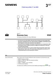
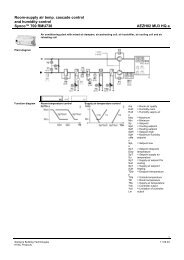
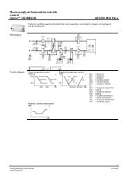
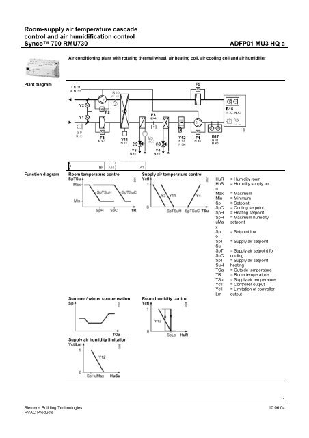
<strong>Room</strong>-<strong>supply</strong> <strong>air</strong> <strong>temperature</strong> <strong>cascade</strong><br />
<strong>control</strong> <strong>and</strong> <strong>air</strong> humidification <strong>control</strong><br />
Synco 700 RMU730 ADFP01 MU3 HQ a<br />
Plant diagram<br />
Function diagram<br />
Air conditioning plant with rotating thermal wheel, <strong>air</strong> heating coil, <strong>air</strong> cooling coil <strong>and</strong> <strong>air</strong> humidifier<br />
<strong>Room</strong> <strong>temperature</strong> <strong>control</strong> Supply <strong>air</strong> <strong>temperature</strong> <strong>control</strong><br />
Summer / winter compensation <strong>Room</strong> humidity <strong>control</strong><br />
Supply <strong>air</strong> humidity limitation<br />
HuR = Humidity room<br />
HuS<br />
u<br />
= Humidity <strong>supply</strong> <strong>air</strong><br />
Max = Maximum<br />
Min = Minimum<br />
Sp = Setpoint<br />
SpC = Cooling setpoint<br />
SpH = Heating setpoint<br />
SpH = Maximum humidity<br />
uMa<br />
x<br />
setpoint<br />
SpL<br />
o<br />
= Setpoint low<br />
SpT<br />
Su<br />
= Supply <strong>air</strong> setpoint<br />
SpT = Supply <strong>air</strong> setpoint for<br />
SuC cooling<br />
SpT = Supply <strong>air</strong> setpoint<br />
SuH heating<br />
TOa = Outside <strong>temperature</strong><br />
TR = <strong>Room</strong> <strong>temperature</strong><br />
TSu = Supply <strong>air</strong> <strong>temperature</strong><br />
Yctl = Controller output<br />
Yctl = Limitation of <strong>control</strong>ler<br />
Lm output<br />
<strong>Siemens</strong> Building Technologies 10.06.04<br />
HVAC Products<br />
1
<strong>Room</strong>-<strong>supply</strong> <strong>air</strong> <strong>temperature</strong> <strong>cascade</strong><br />
<strong>control</strong> <strong>and</strong> <strong>air</strong> humidification <strong>control</strong><br />
Synco 700 RMU730 ADFP01 MU3 HQ a<br />
Description of<br />
functions<br />
St<strong>and</strong>ard<br />
configuration<br />
Optional<br />
configuration<br />
Basic functions Options<br />
• 7-day time switch with holiday / special<br />
day program<br />
• Control of a 2-speed fan<br />
• Control of the <strong>supply</strong> <strong>air</strong> <strong>temperature</strong> via<br />
the heating coil valve <strong>and</strong> the cooling coil<br />
valve in sequence<br />
• Control of room humidity by the <strong>air</strong><br />
humidifier (on comm<strong>and</strong> <strong>and</strong> modulating<br />
positioning signal)<br />
• Frost protection with frost protection<br />
monitor<br />
• Supervision of the <strong>supply</strong> <strong>and</strong> extract <strong>air</strong><br />
fans with differential pressure detectors<br />
• Supervision of the <strong>supply</strong> <strong>and</strong> extract <strong>air</strong><br />
filters with differential pressure detectors<br />
• Limitation of <strong>supply</strong> <strong>air</strong> humidity<br />
Auxiliary functions<br />
• Unoccupied mode (room <strong>temperature</strong><br />
required)<br />
• Outside <strong>temperature</strong> for the following<br />
functions: Summer / winter compensation,<br />
preheating, locking the second fan speed<br />
at low outside <strong>temperature</strong>s, switching on<br />
the heating coil pump at low outside<br />
<strong>temperature</strong>s<br />
• Heat recovery system with Maximum<br />
Economy Changeover (room <strong>and</strong> outside<br />
<strong>temperature</strong> required)<br />
• Control of the heating coil pump, with<br />
pump kick<br />
• Fault relay 1 for urgent faults<br />
• Fault relay 2 for faults that are not urgent<br />
• Supervision of efficiency of the heat<br />
recovery system (room, outside <strong>and</strong><br />
exhaust <strong>air</strong> <strong>temperature</strong> required)<br />
• Remote setpoint adjuster<br />
• 2 additional fault signal inputs<br />
Variants<br />
• <strong>Room</strong> (extract <strong>air</strong>)-<strong>supply</strong> <strong>air</strong> <strong>temperature</strong><br />
<strong>cascade</strong> <strong>control</strong> with minimum <strong>and</strong><br />
maximum limitation of the <strong>supply</strong> <strong>air</strong><br />
<strong>temperature</strong><br />
• Frost protection with frost protection<br />
sensor on the <strong>air</strong> side <strong>and</strong> <strong>control</strong>lerinternal<br />
2-phase frost protection function<br />
• Frost protection with frost protection<br />
sensor on the water side <strong>and</strong> <strong>control</strong>lerinternal<br />
2-phase frost protection function<br />
Legend Type of unit See page Data sheet Type ref. Qty.<br />
N1 Modular universal <strong>control</strong>ler, 3<br />
<strong>control</strong> loops<br />
CE1N3144 RMU730 1<br />
B16 <strong>Room</strong> sensor with LG-Ni 1000 signal<br />
output for <strong>temperature</strong><br />
CM1N1850 QFA65.1 1<br />
B17 Duct sensor with LG-Ni 1000 signal<br />
output <strong>temperature</strong><br />
CM1N1860 QFM65.1 1<br />
F1 Differential pressure detectors CA1N1552 QBM81.. 1<br />
F2 Differential pressure detectors CA1N1552 QBM81.. 1<br />
F3 Frost detectors with capillary tube CA1N1284 QAF81.. 1<br />
F4 Differential pressure detectors CA1N1552 QBM81.. 1<br />
F5 Differential pressure detectors CA1N1552 QBM81.. 1<br />
Y1 2-point damper actuators + G…2…E 1<br />
Y2 2-point damper actuators + G…2…E 1<br />
Y3 3-Port seat valve * VX… 1<br />
Modulating valve actuator, AC 24 V,<br />
DC 0…10 V<br />
S..6... 1<br />
Y4 3-Port seat valve * VX… 1<br />
Modulating valve actuator, AC 24 V,<br />
DC 0…10 V<br />
S..6... 1<br />
For valve sizing, refer to chapter 19<br />
Function<br />
legend<br />
Type of unit See page Data sheet Type ref. Qty.<br />
A7 Universal module (4UI, 4D0) CE1N3146 RMZ787 1<br />
A10 Plug-in user interface CE1N3111 RMZ790 1<br />
B9 Duct <strong>temperature</strong> sensor CM1N1771 QAM22 1<br />
B10 Duct <strong>temperature</strong> sensor CM1N1771 QAM22 1<br />
R5 Setpoint adjuster, passive, universal CA1N1985 BSGN-U1 1<br />
<strong>Siemens</strong> Building Technologies 10.06.04<br />
HVAC Products<br />
2
<strong>Room</strong>-<strong>supply</strong> <strong>air</strong> <strong>temperature</strong> <strong>cascade</strong><br />
<strong>control</strong> <strong>and</strong> <strong>air</strong> humidification <strong>control</strong><br />
Synco 700 RMU730 ADFP01 MU3 HQ a<br />
Variants<br />
Connection<br />
diagram<br />
Legend Type of unit See page Data sheet Type ref. Qty.<br />
A10a Detached user interface CE1N3112 RMZ791 1<br />
B9a Outside sensor CE1N1811 QAC22 1<br />
B16a Duct sensor with LG-Ni 1000 signal<br />
CM1N1860 QFM65.1 1<br />
output <strong>temperature</strong><br />
F3a Immersion <strong>temperature</strong> sensor CM1N1790 QAE26.9 1<br />
+ For actuator sizing <strong>and</strong> selection refer to chapter ....<br />
* For valve sizing <strong>and</strong> selection refer to chapter .....<br />
K1 = Relay contact<br />
"External fault signal 1"<br />
K2 = Relay contact<br />
"External fault signal 2"<br />
M3 = Air heating coil pump<br />
K1 = Relay contact<br />
"External fault signal 1"<br />
K2 = Relay contact<br />
"External fault signal 2"<br />
M3 = Air heating coil pump<br />
Y11 = Control unit for the<br />
rotating heat recovery<br />
device<br />
Y12 = Control unit for the<br />
steam humidifier with<br />
electric steam<br />
generation<br />
Y11 = Control unit for the<br />
rotating heat recovery<br />
device<br />
Y12 = Control unit for the<br />
steam humidifier with<br />
electric steam<br />
generation<br />
Configuration <strong>and</strong> parameter settings<br />
Path: ... > Commissioning > Basic function<br />
Parameter Setting Function Remarks<br />
Plant type A02 Selection of application<br />
Position 1 RMZ787 Selection of auxiliary module Activation of options on auxiliary module<br />
RMZ787<br />
Engineering • A number of settings are plant-specific <strong>and</strong> may need adjusting after the initial commissioning of the<br />
<strong>control</strong>ler<br />
• The connection diagram does not show all plant interlocks but only those directly connected to the<br />
<strong>control</strong>ler or associated equipment<br />
<strong>Siemens</strong> Building Technologies 10.06.04<br />
HVAC Products<br />
3