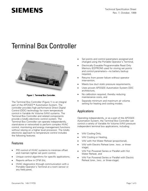
Terminal Box Controller - Siemens
Terminal Box Controller - Siemens
Terminal Box Controller - Siemens

Create successful ePaper yourself
Turn your PDF publications into a flip-book with our unique Google optimized e-Paper software.
<strong>Terminal</strong> <strong>Box</strong> <strong>Controller</strong><br />
Figu gu gure gu e 1. . <strong>Terminal</strong> l <strong>Box</strong> x Con on ontr<br />
troller. tr<br />
The <strong>Terminal</strong> <strong>Box</strong> <strong>Controller</strong> (Figure 1) is an integral<br />
part of the APOGEE� Automation System. The<br />
controller provides high performance Direct Digital<br />
Control (DDC) technology for room temperature<br />
control in Variable Air Volume (VAV) systems. The<br />
<strong>Terminal</strong> <strong>Box</strong> <strong>Controller</strong> and related components<br />
provide a totally electronic control system. The<br />
<strong>Terminal</strong> <strong>Box</strong> <strong>Controller</strong> can operate independently,<br />
stand-alone or networked to perform complex HVAC<br />
control, monitoring and energy management functions<br />
without relying on a higher level processor. The totally<br />
electronic approach to temperature control includes<br />
the following features.<br />
Features<br />
� PID control of HVAC systems to minimize offset<br />
and maintain tighter set point control,<br />
� Unique control algorithms for specific applications,<br />
� Reports airflow in CFM (l/s),<br />
� HVAC diagnostics through communication with a<br />
Portable Operator's <strong>Terminal</strong> at a room sensor or<br />
any field panel,<br />
Technical Specification Sheet<br />
Rev. 7, October, 1998<br />
� Set points and control parameters assigned and<br />
changed using the Portable Operator's <strong>Terminal</strong>,<br />
� Electrically Erasable Programmable Read Only<br />
Memory (EEPROM) used for storing set points<br />
and control parameters�no battery backup<br />
required,<br />
� Returns from power failure without operator<br />
intervention,<br />
� Meets low duct static pressure requirements,<br />
� Uses proven APOGEE Automation System DDC<br />
architecture,<br />
� No calibration required, thereby reducing<br />
maintenance costs, and<br />
� Separate minimum and maximum air volume<br />
setting for heating and cooling modes.<br />
Applications<br />
Operating independently, or as a part of the APOGEE<br />
Automation System, the <strong>Terminal</strong> <strong>Box</strong> <strong>Controller</strong> can<br />
control a variety of Variable Air Volume (VAV) pressure<br />
independent terminal box applications, including:<br />
� VAV Cooling Only,<br />
� VAV Cooling or Heating,<br />
� VAV with Hot Water Reheat (proportional),<br />
� VAV with Electric Reheat (one-, two-, or threestage),<br />
� VAV Fan Powered Series or Parallel with Hot<br />
Water Reheat, and<br />
� VAV Fan Powered Series or Parallel with Electric<br />
Reheat (one-, two-, or three-stage).<br />
Document No. 149-171P25 Page 1 of 5
Description<br />
The <strong>Terminal</strong> <strong>Box</strong> <strong>Controller</strong> consists of a differential<br />
pressure transducer and an electronic controller<br />
assembly. An Autozero Module is available for<br />
mounting on the controller for those applications<br />
where uninterrupted airflow is necessary. A Pneumatic<br />
Transducer provides for control of pneumatic damper<br />
and valve actuators.<br />
Control algorithms are preprogrammed. The controller<br />
is ready to operate after selecting the application and<br />
assigning the unit's controller address with the<br />
Portable Operator's <strong>Terminal</strong>. If desired, the operator<br />
may use the Portable Operator's <strong>Terminal</strong> to adjust<br />
the air volume set points in CFM (l/s), room<br />
temperature set points and other parameters. The<br />
controller is designed for operation and modification<br />
without vendor assistance.<br />
Differential Pressure Transducer<br />
The averaging air velocity sensor (provided by the VAV<br />
terminal unit manufacturer) sends an average air<br />
velocity measurement of the duct air velocity to the<br />
controller. The air velocity sensor connects to the<br />
differential pressure transducer (which is mounted in<br />
the <strong>Terminal</strong> <strong>Box</strong> <strong>Controller</strong>) and measures the<br />
average differential pressure. The <strong>Terminal</strong> <strong>Box</strong><br />
<strong>Controller</strong> converts this value to actual airflow in CFM<br />
(l/s).<br />
Specifications<br />
Temperature Range 48�F to 112�F (9�C to 45�C)<br />
Measurement Range 0 to 4000 fpm (0 to 20 m/s)<br />
Measurement Resolution �4 fpm (�0.02 m/s)<br />
Measurement Accuracy*<br />
300 to 4000 fpm<br />
(1.5 to 20 m/s)<br />
200 to 300 fpm<br />
(1 to 1.5 m/s)<br />
�5% of actual reading<br />
+12% to -15% of actual<br />
reading<br />
Repeatability �8 fpm (0.04 m/s)<br />
*All l specifica ca cations ca s assume e an n un unadjusted un d flow w coe oe oeff oeff<br />
fficien ff en ent<br />
t of f 1.<br />
<strong>Terminal</strong> <strong>Box</strong> <strong>Controller</strong><br />
This controller provides all wiring terminations: input/<br />
output, system and local communication and power.<br />
The cable from the room sensor connects to a RJ-11<br />
jack on the controller. All other connections are<br />
removable terminal blocks. The controller assembly is<br />
mounted on a plastic track that is mounted directly on<br />
the terminal box. An optional enclosure protects the<br />
controller assembly.<br />
The controller interfaces with the following external<br />
devices:<br />
� Averaging air velocity sensor provided by VAV<br />
terminal unit manufacturers,<br />
� Floating control valve and damper actuators,<br />
� Temperature sensors (room, duct, immersion, and<br />
outside air),<br />
� Portable Operator's <strong>Terminal</strong>,<br />
� APOGEE Automation System,<br />
� Digital input devices (dry contacts from motion<br />
sensors, alarm contacts), and<br />
� Digital output devices (fan, stages of electric heat).<br />
Specifications<br />
Power Requirements<br />
Operating Range<br />
Power Consumption<br />
Inputs<br />
Analog<br />
18 to 28 Vac 50 or 60 Hz<br />
3.5 VA (Nominal) to 5.0 VA<br />
(Peak) @ 24 Vac<br />
(plus loads)<br />
<strong>Siemens</strong> Building Technologies, Inc Page 2 of 5<br />
Digital<br />
1 room temperature sensor<br />
1 velocity sensor<br />
1 set point (optional)<br />
1 auxiliary temperature sensor<br />
2 dry contacts<br />
Outputs 6 DO 24 Vac optically isolated<br />
solid state switches @ 0.5 amp<br />
Controlled Temperature �1.5�F (0.9�C)<br />
Accuracy, Heating or<br />
Cooling<br />
Dimensions 4-1/8" W x 7-3/4" L x 1-1/2" H<br />
(105 mm x 197 mm x 38 mm)<br />
Weight approx. 3 lbs. (1.35 kg)<br />
Communications<br />
Remote<br />
Local<br />
Ambient Conditions<br />
Storage Temperature<br />
Operating<br />
Temperature<br />
Humidity Range<br />
Agency Listings<br />
UL Listing<br />
CSA Certified<br />
FCC Compliance<br />
LAN Trunk<br />
Portable Operator's <strong>Terminal</strong><br />
-20�F to 167�F (-29�C 75�C)<br />
32�F to 122�F (0�C to 50�C)<br />
10% to 95% (non-condensing)<br />
UL 916, PAZX,<br />
UL 864, UDTZ
Optional Accessories<br />
Autozero o Module<br />
The optional Autozero Module (Figure 2) is required<br />
when continuous operation at occupied flow is<br />
required for an area. The Autozero Module is<br />
connected to the air velocity inlet ports of the <strong>Terminal</strong><br />
<strong>Box</strong> <strong>Controller</strong> and provides periodic recalibration of<br />
the air velocity transducer without changing air volume<br />
being delivered to a room. This recalibration ensures<br />
long-term precise airflow delivery.<br />
Specifications<br />
Power Consumption 1.5 VA @ 24 Vac max.<br />
Dimensions 2-1/2" W x 2-1/2" H x 1"D<br />
(64 mm x 64 mm x 32)<br />
Weight 0.5 lb. (0.2 kg)<br />
Figu gu gure gu e 2. . Autozero o Module.<br />
Pneumatic Transducer<br />
The PTS Pneumatic Transducer (Figure 3) contains the<br />
transducers that provide the signal conversion from<br />
electronic to pneumatic. The module is piped to the<br />
pneumatic actuator and wired to the <strong>Terminal</strong> <strong>Box</strong><br />
<strong>Controller</strong>. This transducer provides for accurate<br />
control of pneumatic actuators for precise temperature<br />
and air volume control.<br />
Specifications<br />
Maximum Input Pressure 30 psi (207 kPa)<br />
Air Consumption 0 SCIM<br />
Power Consumption 4 VA @ 24 Vac max.<br />
Dimensions 3-1/2" L x 2-1/4" W x 1-1/2" H<br />
(87 mm x 57 mm x 38 mm)<br />
Weight 9 oz (0.3 kg)<br />
Figu gu gure gu e e 3. . PTS S Pneu neu neumatic neu c Transducer.<br />
<strong>Terminal</strong> <strong>Box</strong> <strong>Controller</strong> Communication<br />
Up to 32 <strong>Terminal</strong> <strong>Box</strong> <strong>Controller</strong>s or other <strong>Terminal</strong><br />
Equipment <strong>Controller</strong>s can be connected to each of<br />
the three field panel LAN trunks. Communication with<br />
the <strong>Terminal</strong> <strong>Box</strong> <strong>Controller</strong> can be initiated from any<br />
system field panel on the system network. The<br />
system network does not require additional hardware<br />
to connect <strong>Terminal</strong> Equipment <strong>Controller</strong>s. When<br />
<strong>Terminal</strong> Equipment <strong>Controller</strong>s are wired to a field<br />
panel, features such as energy management<br />
programs, alarm reporting, centralized control,<br />
modification of the system database, system-wide<br />
troubleshooting, and the global commanding of<br />
devices are available to them.<br />
Portable Operator's <strong>Terminal</strong><br />
The DOS-based laptop computer serving as the<br />
Portable Operator's <strong>Terminal</strong> can communicate with<br />
<strong>Terminal</strong> <strong>Box</strong> <strong>Controller</strong>s or any field panel. The<br />
terminal connects to the controller, the room<br />
temperature sensor associated with the <strong>Terminal</strong> <strong>Box</strong><br />
<strong>Controller</strong> or field panel. The terminal can be used to<br />
remotely adjust air volume settings or temperature set<br />
points, to troubleshoot and start-up the system. When<br />
connected to the RS-232 port of a field panel, the<br />
terminal provides system-wide communication. The<br />
terminal uses full English language for all functions,<br />
eliminating the need to remember coded commands.<br />
<strong>Siemens</strong> Building Technologies, Inc. Page 3 of 5
NT0254R1<br />
Third<br />
Party<br />
Devices<br />
¥ Variable<br />
Frequency<br />
Drive<br />
Up to 4 Building<br />
Level Networks<br />
FLN FLN 1 FLN 2 FLN 3 BLN BLN Status Battery<br />
Transmit Receive Receive Receive Receive Transmit<br />
Low<br />
Up to<br />
3 Floor Level<br />
Networks<br />
FLOOR<br />
LEVEL<br />
NETWORK<br />
CONTROLLER<br />
INSIGHT<br />
GRAPHIC<br />
OPERATOR<br />
WORKSTATION<br />
Base or Advanced<br />
PORTABLE<br />
OPERATOR<br />
TERMINAL<br />
FUME HOOD<br />
CONTROLLER<br />
OPERATOR<br />
DISPLAY<br />
PANEL<br />
Figu gu gure gu e 3. . Port rt rtable rt e Operator’s s <strong>Terminal</strong> l Sample e Display.<br />
MANAGEMENT LEVEL NETWORK TCP/IP ETHERNET: Nominal 25 Insight Stations Speed: 10 M bps<br />
MODULAR<br />
EQUIPMENT<br />
CONTROLLER<br />
FUME HOOD<br />
MONITOR<br />
REPORT<br />
PRINTER<br />
BUILDING LEVEL NETWORK Peer To Peer Network: Up to 100 Nodes Per Network-Speed: 9600-115K bp<br />
MODULAR<br />
BUILDING<br />
CONTROLLERS<br />
LAB ROOM<br />
CONTROLLER<br />
<strong>Siemens</strong> Building Technologies, Inc. Page 4 of 5<br />
LED 4<br />
LED 5<br />
LED 6<br />
LED 7<br />
LED 8<br />
LED 9<br />
LED 2 LED 3<br />
TX<br />
RX TX<br />
1 2 3 4 5 6 7 8 9 10 11 12 13 14 15 16<br />
TERMINAL<br />
EQUIPMENT<br />
CONTROLLER<br />
INSIGHT<br />
With Dial Up<br />
Option to MLN<br />
and/or BLN<br />
Heat Pump<br />
Unit Vent<br />
Unit Conditioner<br />
<strong>Terminal</strong> <strong>Box</strong><br />
Constant Volume<br />
Dual Duct-1 AVS<br />
Dual Duct-2 AVS<br />
Room Pressurization<br />
Up to<br />
3 Floor Level<br />
Networks<br />
FLOOR LEVEL NETWORK Standalone DDC Control Network: Up to 32 Devices Per Network<br />
DIGITAL<br />
ENERGY<br />
MONITOR<br />
(ELECTRICAL)<br />
DI1 11<br />
12 DI5<br />
13<br />
14 DI5<br />
15<br />
16 DI5<br />
1 2<br />
DI2 3 4<br />
DI3 5 6<br />
DI4 7 C 57<br />
DO25 NO 58<br />
9<br />
DI5<br />
NC 59<br />
10<br />
C 60<br />
DO26 NO 61<br />
NC 62<br />
C 63<br />
DO27 NO 64<br />
NC 65<br />
8<br />
C 66<br />
DO28 NO 67<br />
NC 68<br />
C 69<br />
DO29 NO 70<br />
NC 71<br />
AO13<br />
25 +<br />
C 72<br />
17 + 26 -<br />
AO9 DO30 NO 73<br />
18 -<br />
AO14<br />
27 +<br />
NC 74<br />
19 + 28 -<br />
AO10 C 75<br />
20 -<br />
AO15<br />
29 +<br />
DO31 NO 76<br />
AO11<br />
21 + 30 -<br />
NC 77<br />
22 - 31 +<br />
AO12<br />
23 +<br />
AO16 C 78<br />
32 -<br />
DO32 NO 79<br />
24 -<br />
NC 80<br />
49 53<br />
50 54<br />
51 55<br />
+ 24 V<br />
52 56<br />
SHIELD<br />
41 +<br />
AI21<br />
33 +<br />
42 -<br />
AI17 34 -<br />
43 +<br />
AI22<br />
35 +<br />
44 -<br />
AI18 36 -<br />
45 +<br />
AI23<br />
37 +<br />
46 -<br />
AI19 38 -<br />
47 +<br />
AI24<br />
39 +<br />
48 -<br />
BLN EXP<br />
AI20 40 -<br />
STATUS TX TX<br />
BLN EXP<br />
MODEM BATT RX RX<br />
STANDALONE<br />
CONTROL UNIT<br />
72 F<br />
DIGITAL<br />
ROOM<br />
SENSOR<br />
REMOTE<br />
BUILDING<br />
CONTROLLER<br />
To<br />
INSIGHT<br />
TO INTEGRATION SYSTEMS<br />
INCLUDING:<br />
Lighting<br />
Fire and Life Safety<br />
Access and Security<br />
Power Monitoring<br />
Programmable Logic Control<br />
Bac Net<br />
LON Talk<br />
HVAC Devices<br />
Other Building Automation<br />
Systems<br />
Figu gu gure gu e e 4. . . APOGEE E E Automation on on Sys ys ystem ys m Architecture e e fr from fr m m Siemen en ens ens<br />
s Buil il ilding il ng ng Techn hn hnolog hn og ogies, og , , Inc, , , Landis s s Division.
Product Ordering Information<br />
Description on Product t Part rt Numbers<br />
<strong>Terminal</strong> <strong>Box</strong> <strong>Controller</strong> 540-100<br />
<strong>Terminal</strong> <strong>Box</strong> <strong>Controller</strong> with Autozero Module 540-200<br />
Pneumatic Transducer PTS4<br />
Document Ordering Information<br />
Specification on Shee hee heet/App hee pp pplica pp ca cation ca on Bull ll lletin ll<br />
Documen en ent en t Part rt Number<br />
Room Temperature Sensors – Series 1000 149-312P25<br />
Duct Sensor 149-134P25<br />
Electronic Damper Actuator<br />
Powers Electronic Valve Actuators:<br />
155-114 (SQR 81.1) or 155-123 (EA 349)<br />
VE 339 2-Way Valve<br />
155-120<br />
VE 339 3-Way Valve<br />
155-121<br />
VE VMP<br />
155-116<br />
Electronic Retrofit Actuator<br />
155-122<br />
Information in this document is based on specifications believed correct at the time of publication. The right is reserved to make changes as design<br />
improvements are introduced. APOGEE is a trademark of <strong>Siemens</strong> Building Technologies, Inc. © 1998 <strong>Siemens</strong> Building Technologies, Inc.<br />
Siemen en ens<br />
s Buil il ilding il ng ng Techn hn hnolog hn og ogies, og , , Inc.<br />
Landis Division<br />
1000 Deerfield Parkway<br />
Buffalo Grove, IL 60089-4513<br />
Printed in the U.S.A. (origin)<br />
Page 5 of 5