3127 Konnex bus KNX - Siemens
3127 Konnex bus KNX - Siemens
3127 Konnex bus KNX - Siemens

Create successful ePaper yourself
Turn your PDF publications into a flip-book with our unique Google optimized e-Paper software.
Use<br />
Synco and <strong>Konnex</strong><br />
CE1N<strong>3127</strong>en<br />
17.01.2003<br />
Preliminary edition 17 Jan 2003<br />
<strong>3127</strong>Z01<br />
3 127<br />
Synco<br />
<strong>Konnex</strong> <strong>bus</strong> <strong>KNX</strong><br />
For devices of the Synco 700, Synco RXB series<br />
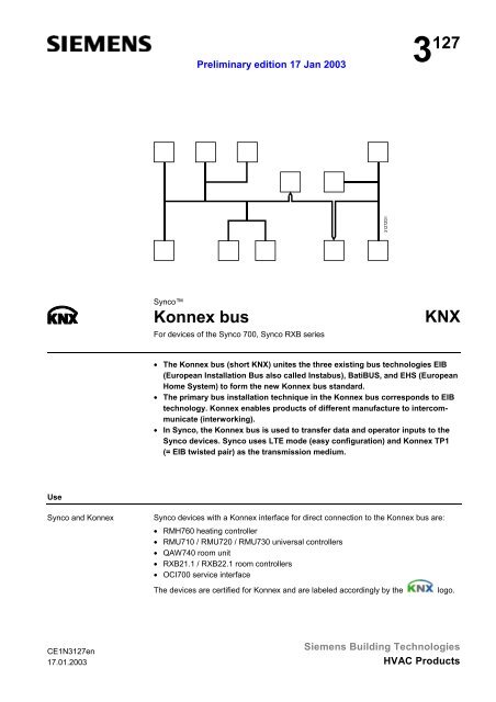
• The <strong>Konnex</strong> <strong>bus</strong> (short <strong>KNX</strong>) unites the three existing <strong>bus</strong> technologies EIB<br />
(European Installation Bus also called Insta<strong>bus</strong>), BatiBUS, and EHS (European<br />
Home System) to form the new <strong>Konnex</strong> <strong>bus</strong> standard.<br />
• The primary <strong>bus</strong> installation technique in the <strong>Konnex</strong> <strong>bus</strong> corresponds to EIB<br />
technology. <strong>Konnex</strong> enables products of different manufacture to intercommunicate<br />
(interworking).<br />
• In Synco, the <strong>Konnex</strong> <strong>bus</strong> is used to transfer data and operator inputs to the<br />
Synco devices. Synco uses LTE mode (easy configuration) and <strong>Konnex</strong> TP1<br />
(= EIB twisted pair) as the transmission medium.<br />
Synco devices with a <strong>Konnex</strong> interface for direct connection to the <strong>Konnex</strong> <strong>bus</strong> are:<br />
• RMH760 heating controller<br />
• RMU710 / RMU720 / RMU730 universal controllers<br />
• QAW740 room unit<br />
• RXB21.1 / RXB22.1 room controllers<br />
• OCI700 service interface<br />
The devices are certified for <strong>Konnex</strong> and are labeled accordingly by the logo.<br />
<strong>Siemens</strong> Building Technologies<br />
HVAC Products
Functions<br />
Transmission medium<br />
Mechanical design<br />
<strong>Konnex</strong> TP1<br />
Bus cable selection<br />
Screened <strong>bus</strong> cable<br />
2/10<br />
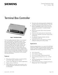
The <strong>Konnex</strong> <strong>bus</strong> serves as a transmission medium:<br />
• To commission and remote control the Synco 700 controllers and the Synco RXB<br />
room controllers by means of the service tool OCI700.1<br />
• To exchange process data between the Synco devices<br />
The simplest form of the "<strong>Konnex</strong> TP1" <strong>bus</strong> comprises a two-core <strong>bus</strong> cable with<br />
stranded lines CE+ (red) and CE– (black).<br />
CE+<br />
CE−<br />
CE+ Red line<br />
CE+ Black line<br />
W Protective layer<br />
W<br />
Select the <strong>bus</strong> cable according to the country-specific offerings by adhering to the<br />
values indicated in the "Technical data" section. Bus cables available in EIB market<br />
countries as per the specifications are:<br />
• YCYM 2x2x0.8 Fixed installation<br />
EIB specification Dry, humid, wet rooms<br />
Outdoors (not exposed to sunlight)<br />
Surface mounted, flush mounted, in pipes<br />
• J-Y(St)Y 2x2x0.8 Fixed installation<br />
EIB specification Indoors only<br />
Surface mounted, in pipes<br />
• JH(St)H2x2x0.8 Halogen-free conductor, laid separately<br />
• A-2Y(L)2Y or A-2YF(L)2Y Underground cable for remote transmission, outdoors<br />
Synco or the <strong>Konnex</strong> <strong>bus</strong> allows for <strong>bus</strong> cables without screening. The screens<br />
available for EIB <strong>bus</strong> cables normally do not need to be connected.<br />
If you use a screened <strong>bus</strong> cable due to expected noise, connect the screen by following<br />
standard installation rules.<br />
<strong>Siemens</strong> Building Technologies Data sheet <strong>Konnex</strong> <strong>bus</strong> Preliminary Editon 17.01.2003 CE1N<strong>3127</strong>en<br />
HVAC Products 17.01.2003<br />
<strong>3127</strong>Z05de
Engineering notes<br />
Network structure<br />
Bus topologies<br />
Note<br />
Network address<br />
Notes<br />
The <strong>Konnex</strong> <strong>bus</strong> is based on a network structure derived from the "European Installation<br />
Bus", EIB. A full <strong>Konnex</strong> network consists of three structural levels. The topmost<br />
level is the backbone line featuring 15 main lines (medium level), each of has another<br />
15 lines (bottom level). The three-level network structure requires area or line couplers.<br />
Without these couplers, the network structure is limited to one single line.<br />
Permissible <strong>bus</strong> topologies at every level are: Tree, line, and star topologies. These<br />
topologies can be mixed as needed. However, ring topologies are not allowed. The tree<br />
topology is advantageous if a large network must be created (refer to "Bus topologies"<br />
at the end of this document).<br />
The term "line" is derived from the EIB environment and refers to the address range of<br />
a line (also referred to as subnet in Synco) and not to the <strong>bus</strong> topology "line".<br />
0.2.003 0.2.254<br />
<strong>Konnex</strong> TP1<br />
0.2.001 0.2.002 0.2.041 0.2.042 0.2.043<br />
Each <strong>bus</strong>-capable Synco device (= <strong>bus</strong> device) in a <strong>Konnex</strong> network must be assigned<br />
a network address.<br />
The network address is composed of the area, line, and device address. The address is<br />
unique and unambiguously identifies the device location in the total network. The network<br />
address in <strong>KNX</strong> is also referred to as "individual address".<br />
• Synco devices having one <strong>Konnex</strong> interface are <strong>bus</strong> devices. These are: Synco 700<br />
controllers RMH / RMU, QAW740 room unit, and Synco RXB room controller.<br />
• If no area or line couplers are used, the <strong>bus</strong> devices use the factory-set area / line<br />
address 0.2.<br />
• If area and line couplers are used and if they are configured accordingly during<br />
commissioning, the area and line addresses are assigned automatically to the <strong>bus</strong><br />
devices.<br />
<strong>Siemens</strong> Building Technologies Data sheet <strong>Konnex</strong> <strong>bus</strong> Preliminary Editon 17.01.2003 CE1N<strong>3127</strong>en<br />
HVAC Products 17.01.2003<br />
3110Z24de<br />
3/10
Factory-set network<br />
address<br />
Device addresses<br />
Principles for<br />
addressing<br />
Max. 64 Synco devices<br />
Notes<br />
Device name<br />
Note<br />
4/10<br />
The <strong>bus</strong>-capable Synco devices are factory-set to network address 0.2.255 with 0 =<br />
area, 2 = line, 255 = device address. The address parts 0.2 (area, line) are displayed<br />
on RMZ79x operator units even though they cannot be changed.<br />
The device addresses must be set during commissioning. The permissible addresses<br />
are in range 1 to 253. Addresses 0 and 255 are predefined:<br />
0 is reserved in each line for the line / area coupler.<br />
255 is the factory-set device address upon delivery.<br />
Devices with address 255 do not send process data on the <strong>Konnex</strong> <strong>bus</strong>. The local<br />
operator unit or the OCI700.1 tool allow for accessing and assigning the device<br />
address.<br />
Address 254 normally is reserved to connect the tool (OCI700.1). (Without address<br />
information, the tool locates the next free address from 254 downward).<br />
Addressing must be designed prior to planning. Assigning addresses is easy even in<br />
complex plants, provided you adhere to the following principles:<br />
• Each device to send and receive data via the <strong>Konnex</strong> <strong>bus</strong> must be assigned a device<br />
address between 1 and 253.<br />
• Each device address may be assigned once only within one particular line (also<br />
called a subnet in Synco). Oftentimes, consecutive numbering starting at 1 is<br />
sufficient.<br />
A maximum of 64 <strong>bus</strong>-capable Synco devices can be installed on one line. These are:<br />
Synco 700 controllers RMH / RMU, QAW740 room unit, and Synco RXB room<br />
controller.<br />
• The Synco 700 option modules RMZ78x and the RMZ79x operator units as well as<br />
the room units on Synco RXB room controllers do not have a <strong>Konnex</strong> interface and<br />
thus are not considered <strong>bus</strong>-capable Synco devices.<br />
• The number of Synco devices in installations using third-party devices (EIB) is<br />
reduced by the number of third-party devices.<br />
An individual device name (e.g. plant designation) consisting of max. 21 characters can<br />
be assigned to each Synco 700 RMH / RMU controller. We recommend to define the<br />
name during planning.<br />
The device name can be written to the controller only by means of the service and<br />
operating tool OCI700.1. The controllers' device names are displayed on the local<br />
operator unit.<br />
The Synco 700 option modules cannot be assigned individual device names (they are<br />
not <strong>bus</strong> devices).<br />
<strong>Siemens</strong> Building Technologies Data sheet <strong>Konnex</strong> <strong>bus</strong> Preliminary Editon 17.01.2003 CE1N<strong>3127</strong>en<br />
HVAC Products 17.01.2003
Zone addressing<br />
<strong>Konnex</strong> LTE mode<br />
Planning zone<br />
addresses<br />
Integrating <strong>bus</strong><br />
devices<br />
Bus load,<br />
E-characteristics<br />
Notes<br />
Clock time master<br />
Notes<br />
Synco uses the <strong>Konnex</strong> LTE mode (LTE = Logical Tag Extended). During<br />
commissioning, several data points are interconnected to a zone address (logical tag),<br />
and are thus assigned to a zone, e.g., outside air temperature, heat/cold distribution<br />
zone, or geographical zone (apartment, room, subzone). The data points having the<br />
same zone address mutually exchange process data.<br />
Complex plants with heating/cold generation/ventilation/individual room control, require<br />
careful planning of zone addresses. The zone addresses are entered using the local<br />
RMZ79x operator units or the service and operating tool OCI700.1 (tool only for Synco<br />
RXB).<br />
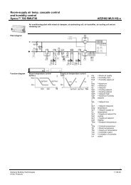
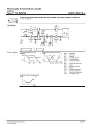
The documentation on basics for the Synco 700 controllers and the function<br />
descriptions of the Synco RXB room controllers contain the associated rules.<br />
The <strong>bus</strong> devices can be integrated anywhere in the <strong>Konnex</strong> <strong>bus</strong> by observing both the<br />
distance between <strong>bus</strong> devices and maximum network size.<br />
Each <strong>bus</strong> device has a particular <strong>bus</strong> load, the E-characteristic. This characteristic is<br />
considered the measure for average data traffic on the <strong>bus</strong> caused by the device.<br />
The E-characteristic must not be calculated for a line featuring the maximum<br />
permissible number of 64 Synco devices, as the E-characteristic sum of 300 is<br />
not reached.<br />
• The sum of the E-characteristics for all devices in a line must be below 300.<br />
• If more than 64 Synco devices will be able to be installed in one line, the Echaracteristics<br />
for all devices must be added to ensure that the limit value of 300 is<br />
not exceeded.<br />
• The E-characteristic is available in the associated data sheet for each Synco device<br />
featuring a <strong>Konnex</strong> interface.<br />
The Synco 700 RMH / RMU controllers can send the time (clock time master) or can<br />
receive the time as slaves, and can synchronize their own clocks.<br />
The device containing the "clock time master" function and those being operated as<br />
slaves or autonomous must be specified during planning. Note that the Synco 700<br />
controllers are factory-set to autonomous.<br />
• In a network, only one Synco 700 controller can be the clock time master.<br />
• An EIB / <strong>Konnex</strong> radio clock may also be the clock time master, but again, no other<br />
device on the <strong>Konnex</strong> network can then be the clock time master.<br />
<strong>Siemens</strong> Building Technologies Data sheet <strong>Konnex</strong> <strong>bus</strong> Preliminary Editon 17.01.2003 CE1N<strong>3127</strong>en<br />
HVAC Products 17.01.2003<br />
5/10
Installation notes<br />
Laying <strong>bus</strong> cables<br />
Important note<br />
Bus line connection<br />
Bus power supply<br />
Decentralized <strong>bus</strong><br />
supply<br />
Centralized <strong>bus</strong> supply<br />
Notes<br />
Terminating resistor<br />
Protection against<br />
lightning and<br />
overvoltage<br />
Important note<br />
6/10<br />
Local regulations on insulation against mains voltage (SELV as per EN 60 730) apply if<br />
the <strong>bus</strong> cable is laid in parallel to lines of a three-phase network (3 x AC 400 V).<br />
The <strong>bus</strong> lines are connected to terminals CE+ (red) and CE– (black). Observe the<br />
polarity of the <strong>bus</strong> lines CE+ and CE– and do not interchange them.<br />
In some devices, CE+ corresponds to <strong>bus</strong> terminal 1, and CE– to <strong>bus</strong> terminal 2. The<br />
<strong>bus</strong> connection are isolated from the device electronics.<br />
The <strong>bus</strong> supply at the controller is referred to as "decentralized <strong>bus</strong> supply" (= DPSU,<br />
decentralized power supply unit). The following applies: Small networks may contain up<br />
to 8 supplying Synco 700 RMH / RMU controllers (see also "Technical data").<br />
As two Synco devices (with or without disabled <strong>bus</strong> supply) can be enabled per supply<br />
controller, a decentralized <strong>bus</strong> supply network may contain up to 24 Synco devices.<br />
A "centralized <strong>bus</strong> supply" (= PSU, power supply unit) is necessary for networks<br />
featuring more than 24 Synco <strong>bus</strong> devices and for networks featuring only Synco RXB<br />
room controllers.<br />
• A <strong>bus</strong> supply is always necessary for <strong>bus</strong> communication, i.e., either a decentralized<br />
or centralized <strong>bus</strong> supply.<br />
• Install the <strong>bus</strong> supply as close to the network center as possible to achieve maximum<br />
network size.<br />
• Synco RMH / RMU controllers in networks with centralized <strong>bus</strong> supply may not<br />
supply the <strong>bus</strong>, i.e., they must be set to Decentral <strong>bus</strong> power supply: Off.<br />
Controllers with Decentral <strong>bus</strong> power supply: On disturb <strong>bus</strong> communication.<br />
<strong>Konnex</strong> networks do not require <strong>bus</strong> terminating resistors.<br />
We recommend overvoltage protection as a simple protective measure for <strong>bus</strong> devices.<br />
The DEHN overvoltage protection by <strong>Siemens</strong>, order number 5WG1 190-8AD01 is a<br />
suitable protection. Refer to CE1P<strong>3127</strong>en for more information.<br />
Depending on the probability of exposure to lighting or overvoltage, complex<br />
overvoltage protection measures covering supply and signal lines (e.g. for outdoor<br />
sensors) must be considered.<br />
Adhere to local regulations on lightning protection and equipotential bonding.<br />
<strong>Siemens</strong> Building Technologies Data sheet <strong>Konnex</strong> <strong>bus</strong> Preliminary Editon 17.01.2003 CE1N<strong>3127</strong>en<br />
HVAC Products 17.01.2003
Commissioning notes<br />
Commissioning<br />
aspects<br />
Check wiring<br />
Check device address<br />
Set device address<br />
Set zone addresses<br />
Assign device name<br />
Technical data<br />
System model<br />
Interface data for Synco<br />
<strong>bus</strong> devices<br />
The following commissioning aspects are an integral part of proper commissioning with<br />
regard to the <strong>Konnex</strong> <strong>bus</strong>.<br />
Check the wiring prior to commissioning, and in particular, make sure that the <strong>bus</strong> lines<br />
are connected to the corresponding terminals CE+ (red) and CE– (black) � The <strong>bus</strong><br />
line polarity cannot be interchanged.<br />
The devices have a factory-set device address of 255. The local operator unit or the<br />
OCI700.1 tool allow for accessing and assigning the device address.<br />
Bus devices communicating on <strong>Konnex</strong> require a project-specific device address<br />
between 1 and 253. The device address can be set by means of the Synco operator<br />
units or the OCI700.1 tool. For Synco RXB, the device address can be set only using<br />
the OCI700.1 tool.<br />
Make sure that the same device address is not assigned twice. If there is a double<br />
assignment, an error message "Same device address" is displayed.<br />
Zone addresses must be assigned to the devices if the plant functions require process<br />
data exchange between the <strong>bus</strong> devices. The local operator units or the OCI700.1 tool<br />
allow for easy assignment. For Synco RXB, the zone address can be set only using the<br />
OCI700.1 tool.<br />
An individual device name (e.g. plant designation) consisting of max. 21 characters can<br />
be assigned to each Synco 700 RMH / RMU controller. The device name can be written<br />
to the controller only by means of the service and operating tool OCI700.1.<br />
<strong>Konnex</strong> <strong>bus</strong> standard as per ISO / OSI (layer model 1 to 7)<br />
Transmission medium (<strong>bus</strong> cable) <strong>Konnex</strong> TP1 (layer 0)<br />
Interface type TP1<br />
Transceiver TP-UART (integrated in device)<br />
Baud rate 9.6 kbps (fixed for TP1)<br />
Transmission mode half duplex<br />
Bus power supply DC 30 V<br />
Power consumption <strong>bus</strong> supply 5 mA (except for QAW740)<br />
Power consumption <strong>bus</strong> supply QAW740 7.5 mA<br />
Bus supply and communication signal decoupled via throttle<br />
(device with integrated throttle)<br />
Polarity for <strong>bus</strong> lines CE+ (red), CE– (black) non-interchangeable<br />
Communication signal<br />
The communication signal (information) is transferred symmetrically to the <strong>bus</strong> lines, i.e., as voltage<br />
difference between the two <strong>bus</strong> lines (and not as a voltage difference to the earthing potential). The sign<br />
preceding the voltage between the <strong>bus</strong> lines CE+ and CE– determine the logical 0 and 1 bit values.<br />
Continued on the next page.<br />
<strong>Siemens</strong> Building Technologies Data sheet <strong>Konnex</strong> <strong>bus</strong> Preliminary Editon 17.01.2003 CE1N<strong>3127</strong>en<br />
HVAC Products 17.01.2003<br />
7/10
Bus cable<br />
Decentralized <strong>bus</strong><br />
supply DPSU<br />
Centralized <strong>bus</strong> supply<br />
PSU<br />
Distances and line<br />
lengths<br />
8/10<br />
Bus cable requirements as per IEC 189-2 (or equivalent)<br />
Cable type two-core, stranded (red/black)<br />
or 2x two-core, stranded (red/black)<br />
(white/yellow)<br />
or spiral quad<br />
Strands min. 5 / m<br />
Diameter min. 0.8 mm, max. 1.0 mm<br />
Wave resistance (ideal value) 120 Ω at 100 kHz<br />
Line resistance 20 Ω/km to max. 75 Ω/km<br />
Capacity, line to line max. 100 pF/m at 800 Hz<br />
Greater values require a proportional<br />
shortage of the perm. cable lengths.<br />
Cable screen not required (Synco devices without<br />
screen connection)<br />
Bus terminating resistor Not required<br />
Bus supply from Synco RMH / RMU controllers 30 V / 25 mA<br />
Controllers with DPSU, Decentral <strong>bus</strong> power supply: On max. 8 per line<br />
Bus devices without DPSU max. 2 per controller with DPSU<br />
Number of <strong>bus</strong> devices on one line max. 24 [8 + (8 x 2)]<br />
Centralized <strong>bus</strong> supply required if line has >24 <strong>bus</strong> devices<br />
or only RXB room controllers<br />
or third-party (EIB) devices<br />
or >2 devices without <strong>bus</strong> supply<br />
per device with <strong>bus</strong> supply<br />
Centralized <strong>bus</strong> supply: Devices with integrated throttle<br />
• EIB voltage supply, 320 mA, REG<br />
Type / Manufacturer SV/S 30.320.5 / ABB<br />
Supplier ID GH Q631 0038 R0111<br />
• EIB voltage supply, 640 mA, REG<br />
Type / Manufacturer SV/S 30.640.5 / ABB<br />
Supplier ID GH Q631 0048 R0111<br />
• Voltage, nominal <strong>bus</strong> supply DC 30 V<br />
(PSU output = DC 30 V / SELV)<br />
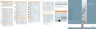
The indications for distances and line lengths in a network are designed for <strong>bus</strong> cables<br />
certified by either EIB or <strong>KNX</strong>.<br />
• The following applies to networks with centralized <strong>bus</strong> supply:<br />
Distance of two power supply units with integrated throttle min. 200 m<br />
Distance to <strong>bus</strong> unit of next neighboring PSU max. 350 m<br />
Distance between <strong>bus</strong> devices max. 700 m<br />
Total length of all lines on one line max.1000 m<br />
• For networks with decentralized <strong>bus</strong> supply, the distances are valid in addition in<br />
dependence of the number of controllers with Decentral <strong>bus</strong> power supply: On (DPSU).<br />
The following applies:<br />
Number of<br />
controllers with<br />
DPSU<br />
Controller with<br />
DPSU<br />
to <strong>bus</strong> device<br />
Maximum distance<br />
Bus device<br />
to <strong>bus</strong> device<br />
Total length of all lines<br />
on one line<br />
1 350 m 350 m max. 350 m<br />
2 350 m 700 m max. 700 m<br />
3 to 8 350 m 700 m max. 1000 m<br />
There is no minimum distance between controllers with DPSU.<br />
<strong>Siemens</strong> Building Technologies Data sheet <strong>Konnex</strong> <strong>bus</strong> Preliminary Editon 17.01.2003 CE1N<strong>3127</strong>en<br />
HVAC Products 17.01.2003
Bus topologies<br />
Advantage:<br />
Tree topology<br />
Branching and<br />
connection variants<br />
Note<br />
Permissible <strong>bus</strong> topologies are: Tree, line, and star topologies. These topologies can<br />
be mixed as needed. However, ring topologies are not allowed.<br />
The tree topology is advantageous if a large network must be created.<br />
Tree topology (with stub lines) Line topology (with loops)<br />
N2 N2<br />
N1 N3 N4 N1 N4<br />
<strong>Konnex</strong> TP1<br />
N6<br />
N1 .. N7 Bus devices<br />
Device with<br />
screw terminals<br />
CE+<br />
CE-<br />
CE+ CE-<br />
N1 .. N8 Bus devices<br />
<strong>Siemens</strong> Building Technologies Data sheet <strong>Konnex</strong> <strong>bus</strong> Preliminary Editon 17.01.2003 CE1N<strong>3127</strong>en<br />
HVAC Products 17.01.2003<br />
N5<br />
<strong>Konnex</strong> TP1<br />
N7 N3<br />
CE+<br />
CE-<br />
T-branch with<br />
<strong>bus</strong> terminal<br />
<strong>3127</strong>Z02<br />
Device with<br />
spring cage terminals<br />
CE+ CE- CE+ CE-<br />
N1 N2 N5 N6<br />
N3<br />
CE+ CE-<br />
N4 N8<br />
In devices featuring spring cage terminals, only one <strong>bus</strong> line can be inserted per spring<br />
cage terminal. For this reason, the CE+ and CE– terminals are available (and connected<br />
inside the device) in double.<br />
N7<br />
<strong>3127</strong>Z06en<br />
9/10
Example 1<br />
Distances<br />
Example 2<br />
Total length<br />
10/10<br />
200 m<br />
100 m<br />
N1<br />
N2<br />
N1 .. N4 Bus devices<br />
150 m<br />
<strong>Siemens</strong> Building Technologies Data sheet <strong>Konnex</strong> <strong>bus</strong> Preliminary Editon 17.01.2003 CE1N<strong>3127</strong>en<br />
HVAC Products 17.01.2003<br />
PSU<br />
400 m<br />
Distance between <strong>bus</strong> device<br />
and <strong>bus</strong> supply max. 350 m.<br />
Not allowed: N4 = 550 m<br />
250 m<br />
100 m<br />
Distance between<br />
<strong>bus</strong> devices max. 700 m.<br />
Not allowed:<br />
N1 to N4 = 900 m<br />
N2 to N4 = 800 m<br />
100 m<br />
100 m<br />
Bus device N4 – by adhering to the maximum distance of 700 m between <strong>bus</strong> devices<br />
– cannot be integrated in the <strong>bus</strong> if <strong>bus</strong> device N3 is integrated with a loop (instead of<br />
sub line).<br />
If a maximum distance of 350 m is kept between the centralized <strong>bus</strong> supply PSU and<br />
the <strong>bus</strong> device (without <strong>bus</strong> supply), the <strong>bus</strong> supply must be placed at location<br />
150 m / 250 m on the line distance 400 m.<br />
200 m<br />
100 m<br />
N1<br />
N2<br />
N1 .. N5 Bus devices<br />
400 m<br />
200 m<br />
100 m<br />
N3<br />
N5<br />
Total lenght<br />
max. 1000 m,<br />
exceeded by<br />
N5<br />
100 m<br />
100 m<br />
The permissible total length of 1000 m in the line is exceeded, if device N5 is integrated<br />
in the <strong>bus</strong> at the given <strong>bus</strong> wiring.<br />
�2003 <strong>Siemens</strong> Building Technologies AG<br />
Subject to change<br />
N3<br />
N4<br />
N4<br />
<strong>3127</strong>Z03en<br />
<strong>3127</strong>Z04en