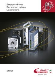
Stepper drives Servostep drives Controllers
Stepper drives Servostep drives Controllers
Stepper drives Servostep drives Controllers

Create successful ePaper yourself
Turn your PDF publications into a flip-book with our unique Google optimized e-Paper software.
SD<br />
Enhanced <strong>drives</strong><br />
Main features<br />
• Multiform Control Modes<br />
• On Board Safety provisions:<br />
√ fully tested for direct installation unit<br />
√ built in watch dog functionality<br />
√ fault monitoring and handling<br />
√ on field working errors buffering<br />
LW1 D 3 0 • Main 5 0 advantages N 0 8 of 1 the - <strong>drives</strong>: 0 0<br />
√ low motor vibration<br />
Description<br />
√ low mechanical noise<br />
√ low heat generation<br />
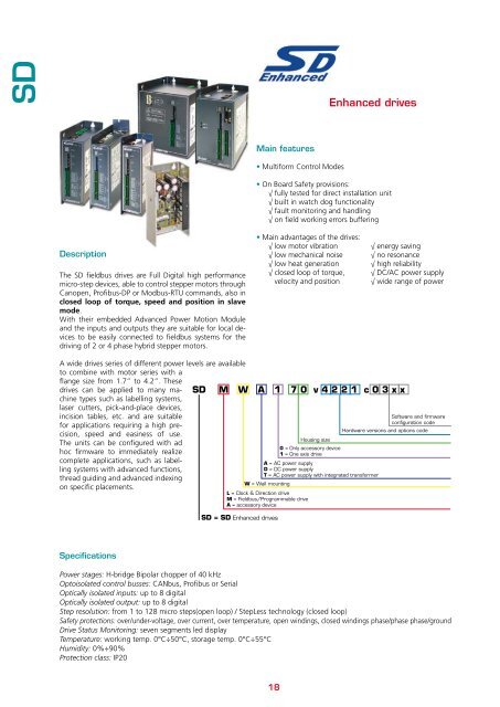
The SD fieldbus <strong>drives</strong> are Full Digital high performance √ closed loop of torque,<br />
micro-step devices, able to control stepper motors through velocity and position<br />
Canopen, Profibus-DP or Modbus-RTU commands, also in<br />
closed loop of torque, speed and position in slave<br />
N = No fieldbus<br />
Max current in Amps *10<br />
mode.<br />
Voltage range code<br />
With their embedded Advanced Power Motion Module<br />
A = AC power supply<br />
and the inputs and outputs they are suitable for local devices<br />
to be easily connected to fieldbus systems LW1= for Wall the mounting hardware controlled <strong>drives</strong><br />
· D = DC power supply<br />
driving of 2 or 4 phase hybrid stepper motors.<br />
Axles number<br />
I/O configuration code<br />
0 = No serial interface<br />
Options code<br />
√ energy saving<br />
√ no resonance<br />
√ high reliability<br />
√ DC/AC power supply<br />
√ wide range of power<br />
S<br />
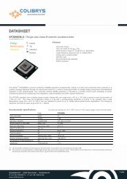
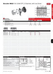
A wide <strong>drives</strong> series of different power levels are available<br />
to combine with motor series with a<br />
flange size from 1.7” to 4.2”. These<br />
<strong>drives</strong> can be applied to many machine<br />
types such as labelling systems,<br />
laser cutters, pick-and-place devices,<br />
incision tables, etc. and are suitable<br />
for applications requiring a high precision,<br />
speed and easiness of use.<br />
The units can be configured with ad<br />
hoc firmware to immediately realize<br />
complete applications, such as labelling<br />
systems with advanced functions,<br />
thread guiding and advanced indexing<br />
on specific placements.<br />
SD<br />
M W A 1 7 0 v 4 2 2 1 c 0 3 x x<br />
L = Clock & Direction drive<br />
M = Fieldbus/Programmable drive<br />
A = accessory device<br />
SD = SD Enhanced <strong>drives</strong><br />
Housing size<br />
0 = Only accessory device<br />
1 = One axis drive<br />
A = AC power supply<br />
D = DC power supply<br />
T = AC power supply with integrated transformer<br />
W = Wall mounting<br />
Software and firmware<br />
configuration code<br />
Hardware versions and options code<br />
Specifications<br />
Power stages: H-bridge Bipolar chopper of 40 kHz<br />
Optoisolated control busses: CANbus, Profibus SM or 2 SerialA 6 60P C 0 4 3 B 4 0 c 0 3 0 0<br />
Optically isolated inputs: up to 8 digital<br />
Optically isolated output: up to 8 digital<br />
Software and firmware<br />
Step resolution: from 1 to 128 micro steps(open loop) / StepLess technology (closed loop)<br />
configuration code<br />
0 = options number<br />
Safety protections: over/under-voltage, over current, over temperature, open windings, closed windings phase/phase phase/ground<br />
N = No encoder<br />
Drive Status Monitoring: seven segments led display<br />
4 = 400 ppr integrated incremental encoder<br />
Temperature: working temp. 0°C÷50°C, storage temp. 0°C÷55°C<br />
Humidity: 0%÷90%<br />
Protection class: IP20<br />
18<br />
A = 3.4 Nm 1/2 stack motor<br />
B = 4.5 Nm 1 stack motor<br />
C = 7.0 Nm 2 stacks motor<br />
D = 8.5 Nm 3 stacks motor<br />
E = 12.5 Nm 4 stacks motor<br />
3 = motor flange dimension (3,4" - 86 mm)<br />
4 = 4 digital inputs and 2 digital outputs<br />
C0 = CANbus interface with in and out connection<br />
P1 = Profibus interface<br />
N3 = RS232 / RS485 interface