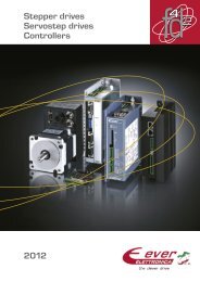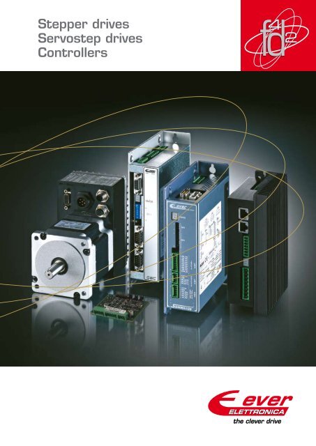
Stepper drives Servostep drives Controllers
Stepper drives Servostep drives Controllers
Stepper drives Servostep drives Controllers

You also want an ePaper? Increase the reach of your titles
YUMPU automatically turns print PDFs into web optimized ePapers that Google loves.
<strong>Stepper</strong> <strong>drives</strong><br />
<strong>Servostep</strong> <strong>drives</strong><br />
<strong>Controllers</strong>
Performance and quality of products and services<br />
The clever drive<br />
“The clever drive” stands for Ever Elettronica’s key design concepts, resulting from<br />
more than thirty years of experience in intelligent <strong>drives</strong> development and based on innovative<br />
full digital hardware and software technologies for synchronous brushless<br />
motors with a high number of poles, commonly known as stepper motors.<br />
Normally used in open loop, these motors can also substitute servomotors with a low<br />
number of poles in closed loop applications, against less cost, an improved easiness of<br />
use and without mechanical gear on the shaft; the reduced dimensions, the good rotor<br />
inertia and the high torque already starting from zero speed with vector sinusoidal phase<br />
excitation, increase the stepper motor performances particularly in terms of dynamics<br />
and positioning precision in applications with direct coupling to the load.<br />
“The Clever Drive” is based on an innovative f 4 d 2 (Fast Forward Feed Full Digital<br />
Drive) technology which, thanks to the velocity of the current regulating calculations,<br />
executed by the drive’s DSPC by means of a Ever Elettronica patented innovative algorithm,<br />
enables the motor excitation at a high chopper frequency and with sinusoidal<br />
phase currents without parasitic harmonics, obtaining in this way a silent and smooth<br />
rotor rotation without resonances, a maximum torque at every speed and a high drive<br />
efficiency.<br />
Also the servostep <strong>drives</strong> with which Ever Elettronica extended the stepper motor<br />
control from the traditional micro-step control in open loop to step-less motor control,<br />
synchronous sinusoidal excitation, unlike micro-step control which doesn’t exclude step<br />
synchronism loss.<br />
The <strong>drives</strong> with full digital f 4 d 2 technology in open loop control and servostep<br />
technology in closed loop control of torque, velocity and position are constituted<br />
as high-end vector sinusoidal <strong>drives</strong> which can replace AC brushless systems, performing<br />
at the same level and against definitely reduced costs, by taking full advantage of<br />
the dynamic features and positioning precision of the stepper motors in applications. AC<br />
or DC power supply, optoisolated inputs, outputs and fieldbus interfaces, extended<br />
and effective protections, full compliance with regulations and product standards, a<br />
reduced number of hardware components, low overheating also when used for high<br />
power applications, mechanical robustness of the motor and a high working temperature<br />
of the feedback elements, are the features which ensure an adequate reliability of<br />
the Ever Elettronica <strong>drives</strong> and motors, also under the heaviest working conditions.<br />
Extended drive lines which, thanks to a fast phase current control by the f 4 d 2 firmware,<br />
with a single DSPC can manage at the same time the motor control and a series of complementary<br />
functions which Ever Elettronica have developed over the years, especially<br />
ready-to-use intelligent motion control modules, IDE for the drive programming<br />
and software to control the <strong>drives</strong> by means of fieldbus and to monitor the drive’s working<br />
status. These functions are available to the user in the form of drive models which are<br />
specified on base of their intelligence level and programmability, housing, power<br />
supply type, number of I/O and communication interfaces. Additionally, to simplify the<br />
switchboard and electrical wiring, there are available integrated <strong>drives</strong> with motor,<br />
drive and feedback encoder, characterized by a minimal thermal dissipation also when<br />
used at maximal power, mechanical robustness and an appropriate reliability of use, also<br />
under heavy working conditions regarding vibrations and temperature.<br />
Specific machine control solutions for various industrial sectors have been implemented<br />
by using Ever Elettronica <strong>drives</strong> of the full digital line in open or closed loop,<br />
working in “master-slave” as well as in “standalone” mode by means of the in the drive<br />
integrated PLC function due to the limited machine time fraction dedicated by the drive’s<br />
DSPC with f 4 d 2 firmware to control the motor. Completed with controllers, gateways<br />
and HMI interfaces, these application solutions are flexible, complete and easy to configure<br />
for particular situations of use and can also constitute a solid starting basis for the<br />
development of new customized solutions for specific client needs.<br />
A reliable service package is offered to our clients that do not just find a new supplier<br />
when working with Ever Elettronica, but a complete and reliable partner with an additional<br />
design department widely experienced in automation, to support their technical<br />
structure.<br />
A price adapted to the daily needs of automated production machinery manufacturers,<br />
is feasible thanks to the completeness of the optimized hardware and software solutions<br />
and the reduction of waste generated during the devices production and thus minimize material<br />
costs without diminishing the performances, robustness, security and reliability of use.<br />
2
f 4 d 2 technology for optimized motor control<br />
in open and closed loop<br />
The f 4 d 2 technology (Fast Forward Feed Full Digital Drive) obtains thanks to<br />
the sinusoidal regulation free of parasitic harmonics and a high chopper frequency<br />
of the phase current, a silent motor rotation from the drive without<br />
resonances, a maximum torque at every speed and high efficiency.<br />
With the servo step <strong>drives</strong> developed for servo performances, Ever Elettronica<br />
have extended the motor control from the traditional micro-step control in<br />
open loop to stepless control with synchronous sinusoidal excitation of the motor<br />
phases, unlike the micro-step control that doesn’t exclude step synchronism<br />
loss, even in presence of fast motor accelerations. The servostep system is realized<br />
with a motor feedback system with an incremental encoder with a resolution<br />
depending on the dynamic accuracy required by the application.<br />
Normally it’s also possible to obtain performances equivalent to brushless systems<br />
performances with inexpensive low-resolution encoders (400 ppr), which can simulate the functioning of a stepper<br />
motor only in combination with a high resolution encoder. In the servostep systems the encoder feedback doesn’t simply<br />
exist of recognizing the occurring step loss during or at the end of the motor movement, but guarantees the continuous rotor<br />
movement synchronism. The stepless phase excitation, characterizing the servostep systems with an optimized excitation<br />
angle to reach a higher velocity and step resolution than when using the micro-step technology, avoids resonances due to<br />
the motor structure and rotor oscillations near the final position.<br />
Moreover, it maximizes the torque generated by the motor to vary the speed and reaction capacity instantly to load changes<br />
obtaining excellent dynamic performances even in presence of almost purely inertial loads and without the need for mechanical<br />
resonance researches (FFT) and module and phase analysis executed for the brushless <strong>drives</strong>.<br />
Open loop and closed loop<br />
TIME IN MILLISECONDS TIME IN MILLISECONDS TIME IN MILLISECONDS<br />
Torque<br />
Closed Loop<br />
Velocity<br />
The servostep <strong>drives</strong> avoid the oversizing occurring in open loop<br />
stepper systems to ensure the correct functioning in all load<br />
situations. They are capable to quickly reach and stabilize<br />
the desired positioning reference tracking value in movements<br />
with a direct coupling to the load until a speed<br />
of 2000 rpm, replacing <strong>drives</strong> with a brushless motor<br />
to diminish costs in applications of which the<br />
resonance frequency varies depending on the load<br />
variation applied to the motor, which makes application<br />
parameterization through automated<br />
learning systems impossible.<br />
All feedback management adjustments to the<br />
programmable <strong>drives</strong> in open loop and servostep<br />
are made by means of RS232 or RS485 serial interfaces<br />
or by CANbus or profibus fieldbus connection,<br />
depending on the used drive version.<br />
Through these interfaces it’s possible to configure<br />
the control parameters of the drive and feedback<br />
loop by means of special software, to execute the application<br />
settings with real time scope monitor and to<br />
manage by means of IDE the programming and debugging<br />
of user applications managed by the firmware of which<br />
the Ever Elettronica <strong>drives</strong> are equipped additionally to the motor<br />
control functions in open and closed loop.<br />
Position<br />
3
Full digital <strong>drives</strong> with additional<br />
extended functionality<br />
Ever Elettronica Full Digital<br />
In the digital f 4 d 2 PWM1<br />
(Fast Forward Feed Full Digital Drive) <strong>drives</strong> of the SlimLine, SD<br />
Enhanced and integrated SM series, the power stages that supply the current<br />
PWM2<br />
40 kHz to the motor are controlled in PWM mode, managed by an innovative firmware<br />
PWM3<br />
owned and patented by Ever Elettronica, and a DSPC (Digital Signal Processor Controller)<br />
that replaces the microprocessor which is generally used in the traditional<br />
PWM4<br />
ADC<br />
<strong>drives</strong> with mixed digital-analogue technology. Thanks to the calculation speed of<br />
the f 4 d 2 technology for the current regulation, the <strong>drives</strong> can realize sophisticated<br />
power supply modes with phase excitation at a high chopper frequency and with sinusoidal currents free of parasitic harmonics<br />
and a silent and smooth rotor rotation without resonances, a maximum torque at every speed and high drive efficiency.<br />
As a minimal number of hardware components are used, the <strong>drives</strong> offer a higher simplicity and reliability. Thanks to the<br />
f 4 d 2 tecnology, a single microprocessor is ables to manage a series of useful complementary features simultaneously with the<br />
motor control, in particular objects for the motion and machines control and solutions based on the typicals Plc functionality<br />
integrated in the <strong>drives</strong>, taking advantage of the small fraction of machine time dedicated to the motor control.<br />
An extremely flexible motor<br />
control is reached thanks to an<br />
optimized phase current regulation by<br />
means of software for the management<br />
of different motion situations to<br />
obtain a sinusoidal regulation without<br />
parasitic harmonics and a high chopper<br />
frequency in micro step mode in open<br />
loop and an always synchronous<br />
stepless mode in closed loop.<br />
Optimized quality, dimensions<br />
and costs are obtained by applying<br />
particularly robust, compact and<br />
surface mounted solutions, based on<br />
full digital technology and having a<br />
reduced number of hardware components<br />
being equipped with extended<br />
hardware protections. The solutions<br />
are designed and produced in accordance<br />
with the directions for hardware<br />
and software products and regulations<br />
for security of use.<br />
Long-term Reliable and stable<br />
performances are obtained thanks<br />
to the completely digital electronics,<br />
the DC or AC power supply, the optoisolated<br />
fieldbus interfaces, and extended<br />
optoisolated control range input and<br />
output lines (5 ÷ 24 Vcc line driver, PNP,<br />
NPN) to simplify the installation.<br />
The <strong>drives</strong> with f 4 d 2 technology used for open loop control and the servostep <strong>drives</strong><br />
used for closed loop control of torque, velocity and position, are configured as highend<br />
sinusoidal vector <strong>drives</strong> making use of the dynamic features and positioning precision<br />
of the stepper motors and improving the qualitative and functional features of<br />
the traditional <strong>drives</strong>, offering the user versatility, an easier installation and a better<br />
devices management.<br />
Silent and smooth motor rotation<br />
even at lower speeds, thanks to<br />
the precise sinusoidal regulation without<br />
harmonics and a high chopper frequency<br />
(40 kHz) of the winding current<br />
in micro-step mode in open loop control<br />
and in permanently synchronous<br />
stepless mode in closed loop control.<br />
GWC<br />
Motion Controller<br />
ENC46<br />
Master Encoder<br />
High<br />
speed<br />
inputs<br />
and<br />
outputs<br />
CANBus Canopen<br />
SM2A<br />
Servomotor with<br />
Integrated Drive,<br />
Control Module<br />
and Encoder<br />
Not required<br />
PLC<br />
Profibus / Devicenet / Modbus<br />
RS232/485 Modbus<br />
SW1<br />
<strong>Stepper</strong> <strong>drives</strong><br />
with Control Module<br />
VT506T<br />
Programmable<br />
Touch screen<br />
MT34FN<br />
Motors<br />
Maximal power efficiency and<br />
less overheating of the motor and the<br />
drive, at motor stand still and when<br />
rotating thanks to the excitation algorithms<br />
of the windings which are optimized<br />
to reach a maximal torque and<br />
a high efficiency at every speed, with<br />
synchronous rectification of the power<br />
stages.<br />
Extended complementary features,<br />
managed by a single DSPC simultaneously<br />
with the motor control,<br />
including ready-to-use intelligent motion<br />
control modules and complete applications<br />
available to the user by means<br />
of drive models that differ from each<br />
other on the field of intelligence level,<br />
programmability, housing, power supply,<br />
number of I/Os and communication<br />
interfaces. Moreover, to simplify the electrical<br />
switchboards and wiring, there are<br />
available integrated drive systems with<br />
motor, drive and feedback encoder.<br />
Specific and flexible Machine control solutions, easily configurable for particular<br />
situations of use in various industrial sectors, are available to the user thanks<br />
to the PLC functionality integrated in the <strong>drives</strong>, working in open as well as in<br />
closed loop, and in “master-slave” and “standalone” mode. Offering a complete<br />
functioning and being equipped with controllers, gateways and HMI interfaces,<br />
these solutions can also constitute a solid starting base for the development of<br />
new customized solutions for specific client needs thanks to the support and services<br />
offered by Ever Elettronica.<br />
4
Machine control solutions dedicated to industries<br />
The product range offered by Ever Elettronica comprises complete hardware and software packages, with an open architecture,<br />
offered to various industrial automation sectors, such as: packaging, labelling, mechano-textile, alimentary, medical,<br />
ceramic machinery, printing, office automation, video surveillance, machine tools, robotics, etc.<br />
Solutions for Industries<br />
Thanks to the experience acquired<br />
over the years and the ability to supply<br />
proven or customized solutions on<br />
base of specific client needs Ever Elettronica<br />
are able to offer a real competitive<br />
advantage to their clients.<br />
The high reliable, versatile and readyto-use<br />
solution packages of Ever Elettronica,<br />
for use in open and closed<br />
loop applications, are equipped with<br />
configuration software and IDE realized<br />
to ensure a fast and easy installation<br />
set up of the client’s application.<br />
On base of their long experience in determining the real needs of the automation market and knowledge about the time and<br />
costs an automatic machines builder normally dedicates to the development of its solutions, Ever Elettronica realized a wide<br />
range of control solutions for the control of automated machines in various industrial sectors.<br />
5
Drives for all applications<br />
SlimLine Drives<br />
Easy-to-use and versatile Smart-Light-Integration-Motion<br />
<strong>drives</strong> line. The Full Digital technology series are developed<br />
to meet the growing demand for high qualitative and fair<br />
priced <strong>drives</strong>, and are characterized by a basic but complete<br />
set of <strong>drives</strong> engineered with the objective to reach the best quality<br />
against restrained production costs.<br />
The line is divided in LW Hardware controlled and SW Software controlled<br />
electronics: to the first category belong all Low End models controlled<br />
by means of digital Step & Direction signals of a master unit (PLC);<br />
the second category includes all High End models configurable through<br />
software by the user to function in fieldbus networks or programmables<br />
by means of eePLC software, an IDE to execute controls in standalone<br />
mode and PLC functions.<br />
SD Enhanced Drives<br />
The SD electronics family is a high performance Full<br />
Digital <strong>drives</strong> series, with advanced functionalities for<br />
micro-step control of the motor in open loop and stepless mode control<br />
in closed loop of torque, velocity and position, controlling the motor<br />
as a servomotor (servo step). The SD series groups f 4 d 2 technology<br />
(Fast Forward Feed Full Digital Drive) devices equipped with firmware<br />
designed to suit every control situation as follows: <strong>drives</strong> controlled by<br />
means of digital or analogue clock & direction signals from a master<br />
unit, <strong>drives</strong> controlled through CANbus fieldbus, profibus or serial interface,<br />
<strong>drives</strong> able to execute standard or customized applications in ‘standalone’<br />
mode, making use of MS Windows PC software environments to<br />
configure the working parameters and <strong>drives</strong> that are free programmable<br />
by the user by means of ATOMIC IDE.<br />
Products lines<br />
Integrated SM <strong>drives</strong><br />
The SM line includes a series of devices based on f 4 d 2 technology<br />
(Fast Forward Feed Full Digital Drive) integrating motor,<br />
intelligent drive and, in the closed loop version with typical servomotor performances<br />
in closed loop of torque, velocity and position an incremental<br />
or absolute feedback encoder. The line is designed to simplify electrical<br />
switchboards and wiring in single or multi axles installations through devices<br />
characterized by a minimal heat dissipation adapted for use at maximal<br />
power, and offering mechanical robustness and reliability of use also under<br />
heavy working conditions regarding vibrations and temperature. The SM<br />
series is composed of devices equipped with firmware designed for CANbus<br />
fieldbus control, profibus or serial interface control, able to work in<br />
‘standalone’ mode in standard or customized applications. The <strong>drives</strong> are<br />
configurable through the working parameters by means of MS Windows PC<br />
software or free programmable by the user by means of ATOMIC IDE.<br />
6
Functionalities available<br />
PRODUCTS<br />
Clock & Direction Drives<br />
with analogue velocity reference<br />
Micro-step controlled in open loop and stepless controlled in closed loop of torque, velocity and position<br />
with the ability to manage the acceleration and deceleration ramps and to control the motor.<br />
Drives for Fieldbus control<br />
Micro-step controlled in open loop and stepless controlled in closed loop of torque, velocity and position with<br />
CANBus Slave (Canopen DS301 / DS402), Profibus Slave(Profibus-DP) or Serial Slave (Modbus-RTU) interface with<br />
Advanced Power Motion Module and firmwares configurable through the working parameters by means of MS<br />
Windows PC software development environments in single or multi axles systems.<br />
Programmable <strong>drives</strong><br />
Micro-step controlled in open loop and stepless controlled in closed loop of torque, velocity and position<br />
equipped with PLC functionalities able to work in standard or customized ‘standalone’ applications and free<br />
programmable by the user by means of IDE software in single or multi axles applications.<br />
Special and Custom Drives<br />
“Open Frame” Drives for the integration with the machine’s electronics.<br />
ASICs<br />
Integrated components for 2/4 phases stepper motor <strong>drives</strong> control.<br />
<strong>Controllers</strong> and Gateways<br />
All in one devices equipped with Motion Controller, Gateway for the communication between different<br />
fieldbusses and PLC for the programming and management of applications.<br />
7
LW<br />
SlimLine <strong>drives</strong><br />
Main features:<br />
• Equipped with advanced safety devices:<br />
√ tested for direct unit installation<br />
√ failures monitoring and handling<br />
Description<br />
The LW1 are a series of high performance micro stepping<br />
<strong>drives</strong> based on precise PWM sinusoidal current control<br />
technology. Thanks to this solution LW1 <strong>drives</strong> are able to<br />
command the stepper motors with lower noise, lower temperature<br />
rise and uniform movements, resulting into higher<br />
performances and speed than most of <strong>drives</strong> available on<br />
the market.The series have a wide power range and are designed<br />
for controlling 2 and 4 phase hybrid stepper motors<br />
from 1.7” to 4.2” NEMA sizes.<br />
As the competitively priced LW1 <strong>drives</strong> are full digital and<br />
realised with surface assembly technology, they offer an extraordinary<br />
reliability and mechanical compactness.<br />
They can be used in many types of machines, such as X-Y<br />
tables,labelling systems, laser cutting systems, pick-place<br />
devices, punching tables, etc., and in all the applications<br />
where versatility, precision, velocity and low temperatures<br />
are required as well.<br />
Order code<br />
• Main advantages of the <strong>drives</strong>:<br />
√ low motor vibrations √ compact dimensions<br />
√ low mechanical noise √ no motor resonance<br />
√ low heat production √ high reliability<br />
√ excellent EMC properties √ easy to set-up<br />
√ safety protections √ high speed and torque drive<br />
√ AC/DC power supply √ wide power range<br />
Power<br />
Versions Power supply Current Digital inputs<br />
LW Models 2014<br />
LW1D2014N081-00<br />
LW Models 2042<br />
LW1D2042N081-00<br />
LW Models 3050<br />
LW1D3050N081-00<br />
LW Models 4080<br />
LW1D4080N0A1-00<br />
LW1D4080N0A1-01<br />
LW1A4080N0A1-00<br />
LW1A4080N0A1-01<br />
LW Models 9060<br />
LW1A9060N081-00<br />
24 ÷ 36 Vac<br />
24 ÷ 36 Vac<br />
24 ÷ 80 Vac<br />
48 ÷ 140 Vac<br />
48 ÷ 140 Vac<br />
36 ÷ 100 Vac<br />
36 ÷ 100 Vac<br />
115 ÷ 230 Vac<br />
LW1 D 3 0 5 0 N 0 8 1 - 0 0<br />
SD<br />
LW1= Wall mounting hardware controlled <strong>drives</strong><br />
8<br />
Voltage range code<br />
A = AC power supply · D = DC power supply<br />
M W A 1 7 0 v 4 2 2 1 c 0 3 x x<br />
0.5 ÷ 1.4 Arms<br />
3 optoisolated<br />
(0.7 ÷ 2.0 Apeak)<br />
5Vac 300 kHz NPN or PNP or Line Driver<br />
Hardware versions and options code<br />
0.2 ÷ 4.2 Arms<br />
Housing size 3 optoisolated<br />
(0.3 ÷ 6.0 Apeak)<br />
5Vac 300 kHz NPN or PNP or Line Driver<br />
0 = Only accessory device<br />
1 = One axis drive<br />
A = AC power supply<br />
D = DC power supply<br />
1.0 ÷ 5.5 ArmsT = AC power supply with integrated 3 optoisolated<br />
transformer<br />
(1.4 ÷ 7.8 Apeak)<br />
5Vac 300 kHz NPN or PNP or Line Driver<br />
W = Wall mounting<br />
1.0 ÷ 8.0 Arms<br />
SD (1.4 = SD ÷ 11.2 Enhanced Apeak) <strong>drives</strong><br />
1.0 ÷ 8.0 Arms<br />
(1.4 ÷ 11.2 Apeak)<br />
1.0 ÷ 8.0 Arms<br />
(1.4 ÷ 11.2 Apeak)<br />
4 optoisolated<br />
5Vac 300 kHz NPN or PNP or Line Driver<br />
4 optoisolated<br />
24Vac 300 kHz NPN or PNP or Line Driver<br />
4 optoisolated<br />
5Vac 300 kHz NPN or PNP or Line Driver<br />
1.0 ÷ 8.0 Arms<br />
4 optoisolated<br />
(1.4 ÷ 11.2 Apeak) 24Vac 300 kHz NPN or PNP or Line Driver<br />
SM 2 A 6 60P C 0 4 3 B 4 0 c 0 3 0 0<br />
1.0 ÷ 6.0 Arms<br />
(1.4 ÷ 8.4 Apeak)<br />
N = No fieldbus<br />
Max current in Amps *10<br />
L = Clock & Direction drive<br />
M = Fieldbus/Programmable drive<br />
A = accessory device<br />
Axles number<br />
I/O configuration code<br />
0 = No serial interface<br />
Options code<br />
Software and firmw<br />
configuration code<br />
Software and firmw<br />
3 optoisolated configuration code<br />
5Vac 300 kHz NPN 0 or = options PNP or number Line Driver<br />
N = No encoder<br />
4 = 400 ppr integrated incremental e<br />
A = 3.4 Nm 1/2 stack motor<br />
B = 4.5 Nm 1 stack motor<br />
C = 7.0 Nm 2 stacks motor<br />
D = 8.5 Nm 3 stacks motor<br />
E = 12.5 Nm 4 stacks motor
Specifications:<br />
Power Stage: 40 kHz bipolar chopper H-Bridge.<br />
Optically isolated inputs: 3 digital inputs, 5 Vdc NPN, PNP or line-driver (300 kHz).<br />
Optically isolated output: 1 digital output, 24 Vdc – 100 mA for driver’s status monitoring.<br />
Step Resolution: full step to 1/256 or 1/250.<br />
Safety Protection: Over/Under Voltage, Over Current, Over Temperature, Short circuit Phase/<br />
Phase and Phase/Ground<br />
Drive Status Monitoring: power LED and failure status LED<br />
Temperature: 0% ÷ 90%<br />
Protection Class: IP20<br />
Control modalities<br />
+10Vcc<br />
Clock & Direction<br />
and Analog Reference<br />
Clock & direction: • Setting of the current<br />
value by means of dip-switches<br />
• Selection of the step angle by means of dip-switches<br />
• Enabling of automatic current reduction<br />
• Possibility to select five user functions by means of jumpers<br />
settings (model 2042 and 3050) or additional dip-switches (model 9060) choosing:<br />
-10Vcc<br />
1 - active edge of step and direction inputs<br />
2 - Step / Direction or Clock-Up / Clock-Down control mode<br />
3 - drive enable input functioning:<br />
a) the motor is powered if the enable input is open<br />
b) the motor is powered if the enable input is closed<br />
4 - ‘Voltage mode’ functioning: when the motor rotation speed exceeds 400 rpm, the drive<br />
switches automatically to full step to compensate the efficiency and torque loss due to current<br />
auto-limitation when the rotation speed increases<br />
5 - maximum current range for precise setting of the desired value<br />
System resources<br />
Mechanical data<br />
Analog inputs Digital outputs Dimensions HxWxD Weitgh<br />
---<br />
1 optoisolated 24 Vac 100 mA<br />
transistor output for Fault<br />
100.0x74.0x37.0 mm<br />
250gr.<br />
---<br />
1 optoisolated 24 Vac 100 mA<br />
transistor output for Fault<br />
100.0x74.0x37.0 mm<br />
250gr.<br />
---<br />
1 optoisolated 24 Vac 100 mA<br />
transistor output for Fault<br />
120.0x97.5x45.5<br />
500 gr.<br />
---<br />
1 optoisolated 24 Vac 100 mA<br />
transistor output for Fault<br />
165.0x97.5x54.3 mm<br />
680 gr.<br />
---<br />
1 optoisolated 24 Vac 100 mA<br />
transistor output for Fault<br />
165.0x97.5x54.3 mm<br />
680 gr.<br />
1 optoisolated 24 Vac 100 mA<br />
transistor output for Fault<br />
165.0x97.5x62.3 mm<br />
900 gr.<br />
1 optoisolated 24 Vac 100 mA<br />
transistor output for Fault<br />
165.0x97.5x62.3 mm<br />
900 gr.<br />
---<br />
1 optoisolated 24 Vac 100 mA<br />
transistor output for Fault<br />
235.0x151.5x62.5 mm<br />
1350 gr.<br />
9
SD<br />
Enhanced <strong>drives</strong><br />
0 8 1 - 0 0<br />
Main features<br />
SW1 A 9 1 6 0 C 0 6 1 - 0 0 c 0 3 0 0<br />
• On board safety provisions:<br />
√ fully tested for direct installation unit<br />
√ built in watch dog functionality<br />
Axles number Description<br />
I/O configuration code<br />
√ fault monitoring and handling<br />
Hardware versions and options code<br />
Axles number<br />
√ on fieeld working errors buffering<br />
0 = No serial interface<br />
I/O configuration code<br />
The SDL drive series are Full Digital high performance microstep<br />
devices based on the precise pwm control technology • Main advantages of the <strong>drives</strong>:<br />
0 = No serial interface · 3 = RS232/ RS422<br />
N = No fieldbus<br />
to regulate the sinusoidal current. Thanks to this solution the √ low motor vibration<br />
· C = CANbus · P = Profibus<br />
√ energy saving<br />
Max current in Amps *10<br />
SDL <strong>drives</strong> are able to control stepper motors through digital √ low mechanical noise √ no resonance<br />
0 = Single power supply<br />
step, direction, rating and starting current signals with less 1 = Separated √ low heat power generation<br />
supply inputs for logic and √ power high reliability<br />
noise, less heating and smooth motion in open as well as Voltage in range √ closed code loop of torque, √ DC/AC power supply<br />
closed loop of torque, velocity and<br />
A = AC power supply velocity · D = DC and power position supply<br />
√ wide range of power<br />
position. Designed for the control of<br />
2 or 4 phase hybrid stepper motors,<br />
SW1= Wall mounting software controlled <strong>drives</strong><br />
a wide range of stepper <strong>drives</strong> with a<br />
different power level are available to<br />
v 4 2 2 1 c be 0 used 3 x with x motor series from 1.7” SD L W T 1 8 0 v A 1 1 4 c 0 2 0 1<br />
to 4.2”. The SDL <strong>drives</strong> offer reliability<br />
and first-class performances and can<br />
o fieldbus<br />
mps *10<br />
er supply<br />
rolled <strong>drives</strong><br />
using size<br />
cessory device<br />
s drive<br />
Options code<br />
Hardware versions and options code<br />
ply<br />
ply<br />
ly with integrated transformer<br />
be used Software in many and firmware types of machines<br />
configuration code<br />
such as such as X-Y-Z tables, laser<br />
cutting systems, pick & place devices,<br />
etc. They are suitable for use in applications<br />
that require a high precision,<br />
speed and easiness of use.<br />
Housing size<br />
0 = Only accessory device<br />
1 = One axis drive<br />
A = AC power supply<br />
D = DC power supply<br />
T = AC power supply with integrated transformer<br />
W = Wall mounting<br />
L = Clock & Direction drive<br />
M = Fieldbus/Programmable drive<br />
A = accessory device<br />
Software and firmware<br />
configuration code<br />
Software and firmware<br />
configuration code<br />
Hardware versions and options code<br />
SW<br />
S<br />
SD = SD Enhanced <strong>drives</strong><br />
4 3 B 4 0 c 0 3 0 0<br />
SM 2 A 6 60P N 3 4 3 C 4 0 c 0 4 9 9<br />
GW<br />
Order code<br />
Software and firmware<br />
configuration code<br />
0 = options number<br />
N = No encoder<br />
4 = 400 ppr integrated incremental encoder<br />
A = 3.4 Nm 1/2 stack motor<br />
B = 4.5 Nm 1 SD stack Models motor 130<br />
C = 7.0 Nm 2 stacks motor<br />
D = 8.5 Nm 3 stacks motor<br />
E = 12.5 Nm 4 stacks motor<br />
Power<br />
Versions Configurations Power supply Current Digital inputs<br />
Logic<br />
SDMWA130vA136 c0420 24 ÷ 48 Vac<br />
3 = motor flange dimension (3,4" - 86 mm)<br />
SD Models 170<br />
4 = 4 digital inputs and 2 digital outputs<br />
Power<br />
A = motore 1/2 stadio da 3,4 Nm<br />
B = motore 1 stadio da 4,5 Nm<br />
C = motore 2 stadi da 7,0 Nm<br />
0.5 ÷ 5.0<br />
D =<br />
Arms<br />
motore 3 stadi da 8,5 Nm 4 optoisolated<br />
E = motore 4 stadi da 12,5 Nm<br />
(0.7 ÷ 7.0 Apeak)<br />
200 kHz 24 Vac NPN o PNP<br />
3 = flangia motore da 3,4” (86 mm)<br />
= CANbus interface with in and out connection<br />
C0 = interfaccia CAN Bus con connessione in/out 4 optoisolated<br />
= Profibus interface<br />
N3 = 1.0 interfaccia ÷ 8.0 RS232 Arms/ RS485<br />
SDLWD170vB211 c0200 24 ÷ 140 Vac<br />
200 kHz 5Vac line-driver or<br />
3 = RS232 / RS485 interface<br />
N2 (2.0 = interfaccia ÷ 11.2 RS485 Apeak) con connessione in/out<br />
2 = RS485 interface with in and out connection<br />
24 Vac PNP<br />
60P = Motore da 6.0 Amps connesso in bipolare parallelo<br />
ps motor in bipolar parallel connection<br />
4 optoisolated<br />
5 = Ingresso di alimentazione 1.0 ÷ separato 8.0 Arms per logica e potenza<br />
supply inputs for logic and power SDLWD170vB211 c0201 24 ÷ 140 6 = Ingresso Vac unico per alimentazione<br />
200 kHz 5Vac line-driver or<br />
ly input<br />
(2.0 ÷ 11.2 Apeak)<br />
A = Alimentazione in AC monofase/trifase<br />
24 Vac PNP<br />
or three phases<br />
D = Alimentazione in DC<br />
2 = Codice interno<br />
Codice firmware<br />
e configurazione software<br />
0 = Numero opzioni<br />
N = nessun encoder<br />
4 = encoder incrementale integrato da 400 ppr<br />
4 = 4 ingressi digitali e 2 uscite digitali<br />
SM = Smart Motor<br />
10
Specifications:<br />
Power stages: H-bridge Bipolar chopper of 40 kHz<br />
Optically isolated inputs:up to 8 digital optoisolated inputs 5 Vdc line driver or 24 Vdc NPN or PNP(200 kHz)<br />
Optically isolated output: 8 digital optoisolated output 24 Vdc – 100 mA (700 mA for 170 models)<br />
Step resolution: from 1 to 128 micro steps<br />
Safety protections: over/under-voltage, over current, over temperature, open windings, closed windings phase/phase phase/ground<br />
Drive Status Monitoring: seven segments LED display.<br />
Temperature: working temp. 0°C÷50°C, storage temp. 0°C÷55°C<br />
Humidity: 0%÷90%<br />
Protection class: IP20<br />
Control modalities<br />
Step & Dir:<br />
Step & Dir with<br />
internal ramps:<br />
Allows the 1-to-1 tracking of the pulses generated by an external axles board that also manages the<br />
acceleration and deceleration ramps. In this way it’s possible to set the step resolution by means of<br />
dipswitches, the current to supply to the motor and the current reduction.<br />
This mode functions like the Step & Dir mode but has also the ability to internally generate the motor<br />
ramp relieving the external axles board from this task. With this mode it’s possible to use the motor<br />
generation boards in a simpler and cheaper way as only the generation of a pulses train at a fixed<br />
frequency is required as the ramps are internally managed by the drive.<br />
Clock & Direction<br />
and Analog Reference<br />
Digital Tracker:<br />
Open Loop Control<br />
Position<br />
Controller<br />
The Digital Tracker mode enables unlike the Step & Dir mode, also the tracking of an external analog<br />
signal and the complete parameterization of the drive by means of serial RS232. Besides the drive’s<br />
configuration parameters (step angle, current, internal ramp, functioning type, etc.) it’s possible to<br />
activate the following features:<br />
set ratio between the reference speed and the motor speed (Gear Ratio);<br />
set min and max full scale of the analog reference (0÷10V or – 10V÷10V);<br />
Enabling/Disabling of the position and velocity feedback (open loop/closed loop);<br />
Set tracking type (clock & dir, clock & dir with internal ramps, tracking of an incremental encoder, speed<br />
tracking of an analog signal).<br />
AMP.<br />
Closed Loop Control<br />
Position<br />
Controller<br />
AMP.<br />
Motor<br />
Motor<br />
+ -<br />
Feedback di<br />
TORQUE - POSITION - VELOCITY<br />
Encoder<br />
• Advantages of Closed Loop Control:<br />
• Compared to an open loop stepper solution;<br />
- Reliable positioning without synchronism loss;<br />
- Keeping stable and automatic recovery of the original position in case of positioning<br />
errors caused by external factors such as mechanic vibrations;<br />
- 100% exploitation of the motor torque;<br />
- Ability to work at high speed in relation to the current control which is regulated<br />
in accordance with the load variations, where the normal open loop systems use a<br />
constant current control at all speeds without taking into account the load variations.<br />
• compared to a brushless servo-controlled solution:<br />
- No need for power regulation (automatic current regulation according to the load<br />
variations);<br />
- Keeping stable of the position without fluctuations after the positioning<br />
completion;<br />
- Fast positioning favoured by the independent control of the integrated DSP;<br />
- Continuous and fast execution of short stroke movements<br />
thanks to the short<br />
positioning time.<br />
+10Vcc<br />
-10Vcc<br />
Other manufacturer controller<br />
System resources<br />
Mechanical data<br />
Digital outputs Analog inputs Interface Control Dimensions Weitgh<br />
2 optoisolated<br />
24 Vac 500 mA<br />
2 ±10 Vac o<br />
potentiometer<br />
Serial<br />
RS232/422/485<br />
Digital Traker/ Analog 86.0x165.0x45.0 mm 560 g.<br />
1 optoisolated<br />
24 Vac 500 mA per Fault<br />
--- --- Clock & direction 175.0x47.7x123.3 mm 700 g.<br />
1 optoisolated<br />
24 Vac 500 mA per Fault<br />
--- ---<br />
Clock & direction<br />
with internal ramps<br />
175.0x47.7x23.3 mm 700 g.<br />
11
SD<br />
Order code<br />
Power<br />
Versions Configurations Power supply Current Digital inputs<br />
SD Models 170<br />
SDMWD170vB231<br />
SDMWD170vB242<br />
SDLWA170v2211<br />
SDLWA170v2211<br />
SDMWA170v2231<br />
SDMWA170v2242<br />
SDMWA170v4231<br />
SDMWA170v4242<br />
SD Models 180<br />
c0420<br />
c0420<br />
c0200<br />
c0201<br />
c0420<br />
c0420<br />
c0420<br />
c0420<br />
Logic<br />
24 + 140<br />
Vac<br />
24 + 140<br />
Vac<br />
24 + 90<br />
Vac<br />
24 + 90<br />
Vac<br />
24 + 90<br />
Vac<br />
24 + 90<br />
Vac<br />
18 Vac<br />
(24 Vdc<br />
user<br />
output)<br />
18 Vac<br />
(24 Vdc<br />
user<br />
output)<br />
Power<br />
24 ÷ 140<br />
Vac<br />
24 ÷ 140<br />
Vac<br />
24 ÷ 90<br />
Vac<br />
24 ÷ 90<br />
Vac<br />
24 ÷ 90<br />
Vac<br />
24 ÷ 90<br />
Vac<br />
24 + 90<br />
Vac<br />
24 + 90<br />
Vac<br />
1.0 ÷ 8.0 Arms<br />
(2.0 ÷ 11.2 Apeak)<br />
1.0 ÷ 8.0 Arms<br />
(2.0 ÷ 11.2 Apeak)<br />
1.0 ÷ 8.0 Arms<br />
(2.0 ÷ 11.2 Apeak)<br />
1.0 ÷ 8.0 Arms<br />
(2.0 ÷ 11.2 Apeak)<br />
1.0 ÷ 8.0 Arms<br />
(2.0 ÷ 11.2 Apeak)<br />
1.0 ÷ 8.0 Arms<br />
(2.0 ÷ 11.2 Apeak)<br />
1.0 ÷ 8.0 Arms<br />
(2.0 ÷ 11.2 Apeak)<br />
1.0 ÷ 8.0 Arms<br />
(2.0 ÷ 11.2 Apeak)<br />
4 optoisolated<br />
200 kHz 5Vac line-driver or<br />
24 Vac PNP<br />
8 optoisolated<br />
200 kHz 5Vac line-driver or<br />
24 Vac PNP<br />
4 optoisolated<br />
200 kHz 5Vac line-driver or<br />
24 Vac PNP<br />
4 optoisolated<br />
200 kHz 5Vac line-driver or<br />
24 Vac PNP<br />
4 optoisolated<br />
200 kHz 5Vac line-driver or<br />
24 Vac PNP<br />
8 optoisolated<br />
200 kHz 5Vac line-driver or<br />
24 Vac PNP<br />
4 optoisolated<br />
200 kHz 5Vac line-driver or<br />
24 Vac PNP<br />
8 optoisolated<br />
200 kHz 5Vac line-driver or<br />
24 Vac PNP<br />
SDLWD180vA114 c0200 24 ÷ 70 Vac<br />
SDLWD180vA114 c0201 24 ÷ 70 Vac<br />
SDMWD180vA133 c0420 24 ÷ 70 Vac<br />
SDMWD180vA143 c0420 24 ÷ 70 Vac<br />
SDLWA180vA114 c0200 24 ÷ 48 Vac<br />
SDLWA180vA114 c0201 24 ÷ 48 Vac<br />
SDMWA180vA133 c0420 24 ÷ 48 Vac<br />
SDMWA180vA143 c0420 24 ÷ 48 Vac<br />
SDLWT180vA114 c0200 115 ÷ 230 Vac<br />
SDLWT180vA114 c0201 115 ÷ 230 Vac<br />
SDMWT180vA133 c0420 115 ÷ 230 Vac<br />
SDMWT180vA143 c0420 115 ÷ 230 Vac<br />
0.5 ÷ 5.0 Arms<br />
(0.7 ÷ 7.0 Apeak)<br />
0.5 ÷ 5.0 Arms<br />
(0.7 ÷ 7.0 Apeak)<br />
0.5 ÷ 5.0 Arms<br />
(0.7 ÷ 7.0 Apeak)<br />
0.5 ÷ 5.0 Arms<br />
(0.7 ÷ 7.0 Apeak)<br />
0.5 ÷ 5.0 Arms<br />
(0.7 ÷ 7.0 Apeak)<br />
0.5 ÷ 5.0 Arms<br />
(0.7 ÷ 7.0 Apeak)<br />
0.5 ÷ 5.0 Arms<br />
(0.7 ÷ 7.0 Apeak)<br />
0.5 ÷ 5.0 Arms<br />
(0.7 ÷ 7.0 Apeak)<br />
0.5 ÷ 5.0 Arms<br />
(0.7 ÷ 7.0 Apeak)<br />
0.5 ÷ 5.0 Arms<br />
(0.7 ÷ 7.0 Apeak)<br />
0.5 ÷ 5.0 Arms<br />
(0.7 ÷ 7.0 Apeak)<br />
0.5 ÷ 5.0 Arms<br />
(0.7 ÷ 7.0 Apeak)<br />
4 optoisolated<br />
200 kHz 5Vac line-driver<br />
or 24 Vac PNP<br />
4 optoisolated<br />
200 kHz 5Vac line-driver<br />
or 24 Vac PNP<br />
4 optoisolated<br />
200 kHz 5Vac line-driver<br />
or 24 Vac PNP<br />
4 optoisolated<br />
200 kHz 5Vac line-driver<br />
or 24 Vac PNP<br />
4 optoisolated<br />
200 kHz 5Vac line-driver<br />
or 24 Vac PNP<br />
4 optoisolated<br />
200 kHz 5Vac line-driver<br />
or 24 Vac PNP<br />
4 optoisolated<br />
200 kHz 5Vac line-driver<br />
or 24 Vac PNP<br />
4 optoisolated<br />
200 kHz 5Vac line-driver<br />
or 24 Vac PNP<br />
4 optoisolated<br />
200 kHz 5Vac line-driver<br />
or 24 Vac PNP<br />
4 optoisolated<br />
200 kHz 5Vac line-driver<br />
or 24 Vac PNP<br />
4 optoisolated<br />
200 kHz 5Vac line-driver<br />
or 24 Vac PNP<br />
4 optoisolated<br />
200 kHz 5Vac line-driver<br />
or 24 Vac PNP<br />
12
System resources<br />
Mechanical data<br />
Digital outputs Analog inputs Interface Control Dimensions Weitgh<br />
4 optoisolated<br />
24 Vac 500 mA<br />
1 ±10 Vac or<br />
potentiometer<br />
Serial<br />
RS232/422/485<br />
Digital Traker / Analog<br />
/ closed loop<br />
175.0x47.7x123.3<br />
mm<br />
770 g.<br />
8 optoisolated<br />
24 Vac 500 mA<br />
1 optoisolated<br />
24 Vac 500 mA per Fault<br />
1 ±10 Vac or<br />
potentiometer<br />
Serial<br />
RS232/422/485<br />
1 optoisolated<br />
24 Vac 500 mA per Fault --- ---<br />
Digital Traker / Analog<br />
/ closed loop<br />
--- --- Clock & direction<br />
Clock & direction<br />
with internal ramps<br />
175.0x47.7x123.3<br />
mm<br />
175.0x88.3x123.3<br />
mm<br />
175.0x88.3x123.3<br />
mm<br />
770 g.<br />
760 g.<br />
760 g.<br />
Clock & Direction<br />
and Analog Reference<br />
4 optoisolated<br />
24 Vac 500 mA<br />
1 ±10 Vac or<br />
potentiometer<br />
Serial<br />
RS232/422/485<br />
Digital Traker / Analog<br />
/ closed loop<br />
175.0x88.3x123.3<br />
mm<br />
800 g.<br />
8 optoisolated<br />
24 Vac 500 mA<br />
1 ±10 Vac or<br />
potentiometer<br />
Serial<br />
RS232/422/485<br />
Digital Traker / Analog<br />
/ closed loop<br />
175.0x88.3x123.3 800 g.<br />
4 optoisolated<br />
24 Vac 500 mA<br />
1 ±10 Vac or<br />
potentiometer<br />
Serial<br />
RS232/422/485<br />
Digital Traker / Analog<br />
/ closed loop<br />
175.0x88.3x123.3<br />
mm<br />
800 g.<br />
8 optoisolated<br />
24 Vac 500 mA<br />
1 ±10 Vac or<br />
potentiometer<br />
Serial<br />
RS232/422/485<br />
Digital Traker / Analog<br />
/ closed loop<br />
175.0x88.3x123.3<br />
mm<br />
800 g.<br />
2 optoisolated<br />
24 Vac 100 mA<br />
transistor output<br />
for Fault and Busy<br />
--- --- Clock & direction<br />
175.0x47.7x123.3<br />
mm<br />
680 g.<br />
2 optoisolated<br />
24 Vac 100 mA<br />
transistor output<br />
for Fault and Busy<br />
--- ---<br />
Clock & direction<br />
with internal ramps<br />
175.0x47.7x123.3<br />
mm<br />
680 g.<br />
mm<br />
3 optoisolated<br />
24 Vac 100 mA<br />
transistor output<br />
2 ±10 Vac or<br />
potentiometer<br />
Serial<br />
RS232/422/485<br />
Digital Traker / Analog<br />
/ closed loop<br />
175.0x47.7x123.3<br />
mm<br />
680 g.<br />
3 optoisolated<br />
24 Vac 100 mA<br />
transistor output<br />
2 ±10 Vac or<br />
potentiometer<br />
Serial<br />
RS232/422/485<br />
Digital Traker / Analog<br />
/ closed loop<br />
175.0x47.7x123.3<br />
mm<br />
680 g.<br />
2 optoisolated<br />
24 Vac 100 mA<br />
transistor output<br />
for Fault and Busy<br />
--- --- Clock & direction<br />
175.0x47.7x123.3<br />
mm<br />
730 g.<br />
2 optoisolated<br />
24 Vac 100 mA<br />
transistor output<br />
for Fault and Busy<br />
--- ---<br />
Clock & direction<br />
with internal ramps<br />
175.0x47.7x123.3<br />
mm<br />
730 g.<br />
3 optoisolated<br />
24 Vac 100 mA<br />
transistor output<br />
2 ±10 Vac or<br />
potentiometer<br />
Serial<br />
RS232/422/485<br />
Digital Traker / Analog<br />
/ closed loop<br />
175.0x47.70x123.3<br />
mm<br />
810 g.<br />
3 optoisolated<br />
24 Vac 100 mA<br />
transistor output<br />
2 ±10 Vac or<br />
potentiometer<br />
Serial<br />
RS232/422/485<br />
Digital Traker / Analog<br />
/ closed loop<br />
175.0x47.7x123.3<br />
mm<br />
810 g.<br />
2 optoisolated<br />
24 Vac 100 mA<br />
transistor output<br />
for Fault and Busy<br />
--- --- Clock & direction<br />
175.0x118.0x124.3<br />
mm<br />
1300 g.<br />
2 optoisolated<br />
24 Vac 100 mA<br />
transistor output<br />
for Fault and Busy<br />
--- ---<br />
Clock & direction<br />
with internal ramps<br />
175.0x118.0x124.3<br />
mm<br />
1300 g.<br />
3 optoisolated<br />
24 Vac 100 mA<br />
transistor output<br />
2 ±10 Vac or<br />
potentiometer<br />
Serial<br />
RS232/422/485<br />
Digital Traker / Analog<br />
/ closed loop<br />
175.0x118.6x124x3<br />
mm<br />
1500 g.<br />
3 optoisolated<br />
24 Vac 100 mA<br />
transistor output<br />
2 ±10 Vac or<br />
potentiometer<br />
Serial<br />
RS232/422/485<br />
Digital Traker / Analog<br />
/ closed loop<br />
175.0x118.6x124x3<br />
mm<br />
1500 g.<br />
13
SW<br />
SlimLine <strong>drives</strong><br />
Main features<br />
• Multiform control modes<br />
• On Board Safety provisions:<br />
√ fully tested for direct installation unit<br />
√ built in watch dog functionality<br />
√ fault monitoring and handling<br />
√ separated power supply for logic and power<br />
√ on field working errors buffering<br />
8 1 - 0 0<br />
0 = No serial interface<br />
Description<br />
The SW are a <strong>drives</strong> series with local logic which can be<br />
connected in slave mode to single or multi-axles systems<br />
through a CANBus (Canopen DS301/DS402), Profibus<br />
(Profibus-DP) or serial (Modbus-RTU) connection. Many<br />
control modes with advanced functionalities can be applied<br />
thanks to the integral PowerMotion<br />
Module and the availability of<br />
high speed inputs and outputs. The<br />
application set-up and debugging<br />
take place by configuring all parameters<br />
through software, making use<br />
of the software interface for PC Windows<br />
named SL-Monitor.<br />
A wide range of stepper <strong>drives</strong> of<br />
different power levels, designed to<br />
control 2 or 4 phase hybrid stepper<br />
motors, are available to combine<br />
with motor series ranging from 1.7”<br />
to 4.2”. The Full digital and competitively<br />
priced SW1 <strong>drives</strong>, realized with<br />
surface mounting technology, offer<br />
reliability and mechanical compactness.<br />
The <strong>drives</strong> are suitable for applications that require<br />
v 4 2 2 1 c axles 0 3 synchronization, x x versatility, accuracy, a high execution<br />
speed and low operating temperatures.<br />
o fieldbus<br />
mps *10<br />
er supply<br />
I/O configuration code<br />
olled <strong>drives</strong><br />
Axles number<br />
Options code<br />
• Main advantages of the <strong>drives</strong>:<br />
√ low motor vibration √ compact sizes<br />
√ low mech. noise √ low heat generation<br />
√ no resonance √ high reliability<br />
√ safe protections √ high speed and torque output<br />
√ DC/AC power supply √ wide range of power<br />
SW1 A 9 1 6 0 C 0 6 1 - 0 0 c 0 3 0 0<br />
Voltage range code<br />
Max current in Amps *10<br />
A = AC power supply · D = DC power supply<br />
SW1= Wall mounting software controlled <strong>drives</strong><br />
Axles number<br />
I/O configuration code<br />
Hardware versions and options code<br />
0 = No serial interface · 3 = RS232/ RS422<br />
N = No fieldbus · C = CANbus · P = Profibus<br />
0 = Single power supply<br />
1 = Separated power supply inputs for logic and power<br />
SD L W T 1 8 0 v A 1 1 4 c 0 2 0 1<br />
Software and firmware<br />
configuration code<br />
SW<br />
SD<br />
sing size<br />
essory device<br />
drive<br />
ly<br />
ly<br />
ly with integrated transformer<br />
Software and firmware<br />
configuration code<br />
Specifications<br />
Hardware versions and options code<br />
Housing size<br />
Software and firmware<br />
configuration code<br />
Hardware versions and options code<br />
Power stages: H-bridge Bipolar chopper of 40 kHz<br />
0 = Only accessory device<br />
1 = One axis drive<br />
Optically isolated inputs: up to 8 digital optoisolated inputs 5 Vdc line driver or 24 Vdc NPN or PNP(200 kHz)<br />
A = AC power supply<br />
Optically isolated output: 8 digital optoisolated output 24 Vdc – 100 mA (700 mA for 170 models)<br />
D = DC power supply<br />
Analog Input: 2± 10 Vdc or for potentiometer<br />
T = AC power supply with integrated transformer<br />
Step resolution: from 1 to 128 micro steps<br />
W = Wall mounting<br />
Safety protections: over/under-voltage, over current, L over = Clock temperature, & Direction drive open windings, closed windings phase/phase phase/<br />
M = Fieldbus/Programmable drive<br />
ground<br />
A = accessory device<br />
Drive Status Monitoring: seven segments display or 2 status LEDs<br />
SD = SD Enhanced <strong>drives</strong><br />
Temperature: working temp. 0°C÷50°C, storage temp. 0°C÷55°C<br />
Humidity: 0%÷90%<br />
Protection class: IP20<br />
4 3 B 4 0 c 0 3 0 0 SM 2 A 6 60P N 3 4 3 C 4 0 c 0 4 9 9<br />
14<br />
GW
Control modalities<br />
• Velocity Control Mode<br />
• Wide range of Positioning Control Modes (homing, relative, absolute, target)<br />
• Electric Gear with programmable gear ratio to track external master reference<br />
(from fieldbus or incremental encoder) of motor Speed and Position<br />
• High speed I/O triggered motor start & stop to event synchronizing for fast<br />
response demanding application: labelling, nick_finder, on fly cut., etc ...<br />
• Multi Axis movements synchronization capability<br />
• On fly change among any Motion Module Control Modes<br />
• On fly Electric Gear Enable/Disable capability<br />
• Motor Stall detection & Target Position tracking through encoder feedback<br />
• The control by commands deriving from a master controller is suitable for multi-axles systems existing of up to 127 <strong>drives</strong>.<br />
The integrated power Motion module ensure a perfect syncrhonization between the axles and reduce the wokload of<br />
the master controller.<br />
Homing Motion Profile:<br />
Mixed Motion Profile<br />
Homing sensor<br />
Motor speed<br />
Motor position<br />
Optional homing offset<br />
Motor position<br />
Optional homing offset<br />
a a a a c c a ab<br />
b<br />
Homing sensor<br />
a = new target position<br />
b = change of the target position<br />
c = change of the motor speed<br />
FIELDBUS CONTROL<br />
Multi-axles synchronization<br />
Motor speed<br />
s = new command from the master controller<br />
Motor 1<br />
Motor 2<br />
CANopen Slave Mode - c0300<br />
s s s s s s<br />
CANBus<br />
Master Controller<br />
Modbus Slave Mode - c0400<br />
RS232 / RS422 / RS485<br />
Half/Full duplex<br />
Profibus-DP Slave Mode - c0700<br />
Profibus<br />
DeviceNet<br />
The software tool for windows Pc SL_Monitor<br />
allows the settings of the drive’s parameters<br />
and a a quick and easy application debug.<br />
Profibus or DeviceNet Slave Mode<br />
CANBus<br />
Up to 25 <strong>drives</strong><br />
controlled by the<br />
GWC unit.<br />
15
SW<br />
Order code<br />
Power<br />
Versions Configurations Power supply Current Digital inputs<br />
SW Models 2142<br />
SW1D2142C061-00<br />
c0300<br />
Logic<br />
24 ÷ 40<br />
Vac<br />
Power<br />
24 ÷ 40<br />
Vac<br />
4.2 Arms<br />
(6.0 Apeak)<br />
4 optoisolated 200 kHz 5Vac<br />
line driver or 24 Vac PNP<br />
SW1D2142N361-00<br />
c0400<br />
24 ÷ 40<br />
Vac<br />
24 ÷ 40<br />
Vac<br />
4.2 Arms<br />
(6.0 Apeak)<br />
4 optoisolated 200 kHz 5Vac<br />
line driver or 24 Vac PNP<br />
SW1A2142P161-00<br />
c0700<br />
18 ÷ 30<br />
Vac<br />
18 ÷ 30<br />
Vac<br />
4.2 Arms<br />
(6.0 Apeak)<br />
4 optoisolated 200 kHz 5Vac<br />
line driver or 24 Vac PNP<br />
SW Models 4080<br />
SW1D4080C061-00<br />
c0300<br />
48 ÷ 140<br />
Vac<br />
48 ÷ 140<br />
Vac<br />
8.0 Arms<br />
(11.0 Apeak)<br />
4 optoisolated 200 kHz 5Vac<br />
line driver or 24 Vac PNP<br />
SW1D4080N361-00<br />
c0400<br />
48 ÷ 140<br />
Vac<br />
48 ÷ 140<br />
Vac<br />
8.0 Arms<br />
(11.0 Apeak)<br />
4 optoisolated 200 kHz 5Vac<br />
line driver or 24 Vac PNP<br />
SW1A4080C061-00<br />
c0300<br />
36 ÷ 100<br />
Vac<br />
36 ÷ 100<br />
Vac<br />
8.0 Arms<br />
(11.0 Apeak)<br />
4 optoisolated 200 kHz 5Vac<br />
line driver or 24 Vac PNP<br />
SW1A4080C0B1-00<br />
c0300<br />
36 ÷ 100<br />
Vac<br />
36 ÷ 100<br />
Vac<br />
8.0 Arms<br />
(11.0 Apeak)<br />
16 optoisolated<br />
SW1A4080N361-00<br />
c0400<br />
36 ÷ 100<br />
Vac<br />
36 ÷ 100<br />
Vac<br />
8.0 Arms<br />
(11.0 Apeak)<br />
4 optoisolated 200 kHz 5Vac<br />
line driver or 24 Vac PNP<br />
SW1A4080N3B1-00<br />
c0400<br />
36 ÷ 100<br />
Vac<br />
36 ÷ 100<br />
Vac<br />
8.0 Arms<br />
(11.0 Apeak)<br />
16 optoisolated<br />
SW1A4080P161-00<br />
c0700<br />
36 ÷ 100<br />
Vac<br />
36 ÷ 100<br />
Vac<br />
8.0 Arms<br />
(11.0 Apeak)<br />
4 optpisolate 200 kHz 5Vac line<br />
driver or 24 Vac PNP<br />
SW Models 9060<br />
SW1A9060C061-00 c0300 115 ÷ 230 Vac<br />
6.0 Arms<br />
(8.46 Apeak)<br />
4 optoisolated 200 kHz 5Vac<br />
line driver or 24 Vac PNP<br />
SW1A9060N361-00 c0400 115 ÷ 230 Vac<br />
SW Models 9160<br />
6.0 Arms<br />
(8.46 Apeak)<br />
4 optoisolated 200 kHz 5Vac<br />
line driver or 24 Vac PNP<br />
SW1A9160C061-00<br />
c0300<br />
115 ÷ 230<br />
Vac<br />
115 ÷ 230<br />
Vac<br />
6.0 Arms<br />
(8.46 Apeak)<br />
4 optoisolated 200 kHz 5Vac<br />
line driver or 24 Vac PNP<br />
SW1A9160C0C1-00<br />
c0300<br />
115 ÷ 230<br />
Vac<br />
115 ÷ 230<br />
Vac<br />
6.0 Arms<br />
(8.46 Apeak)<br />
16 optoisolated<br />
SW1A9160N361-00<br />
c0400<br />
115 ÷ 230<br />
Vac<br />
115 ÷ 230<br />
Vac<br />
6.0 Arms<br />
(8.46 Apeak)<br />
4 optoisolated 200 kHz 5Vac<br />
line driver or 24 Vac PNP<br />
SW1A9160N3C1-00<br />
c0400<br />
115 ÷ 230<br />
Vac<br />
115 ÷ 230<br />
Vac<br />
6.0 Arms<br />
(8.46 Apeak)<br />
16 optoisolated<br />
SW1A9160P161-00<br />
c0700<br />
115 ÷ 230<br />
Vac<br />
115 ÷ 230<br />
Vac<br />
6.0 Arms<br />
(8.46 Apeak)<br />
4 optoisolated 200 kHz 5Vac<br />
line driver or 24 Vac PNP<br />
16
System resources<br />
Mechanical data<br />
Digital outputs Analog inputs Interface Protocol Dimensions Weitgh<br />
2 optoisolated<br />
24 Vac 100 mA<br />
2 ±10Vac or<br />
potentiometer<br />
CANbus CANopen 142.0x74.0x37.0 mm 500 g.<br />
2 optoisolated<br />
24 Vac 100 mA<br />
2 ±10Vac or<br />
potentiometer<br />
Serial<br />
RS232/422/485<br />
Modbus-RTU 142.0x74.0x37.0 mm 500 g.<br />
2 optoisolated<br />
24 Vac 100 mA<br />
2 ±10Vac or<br />
potentiometer<br />
Profibus<br />
Serial RS232<br />
Profibus-DP 142.0x74.0x55.0 mm 500 g.<br />
2 optoisolated<br />
24 Vac 100 mA<br />
2 optoisolated<br />
24 Vac 100 mA<br />
2 optoisolated<br />
24 Vac 100 mA<br />
2 ±10Vac or<br />
potentiometer<br />
2 ±10Vac or<br />
potentiometer<br />
2 ±10Vac or<br />
potentiometer<br />
CANbus CANopen 165.0x97.5x54.3 mm 680 g.<br />
Serial<br />
RS232/422/485<br />
Modbus-RTU 165.0x97.5x54.3 mm 680 g.<br />
CANbus CANopen 165.0x97.5x62.3 mm 900 g.<br />
FIELDBUS CONTROL<br />
10 optoisolated<br />
24 Vac 100 mA<br />
2 ±10Vac or<br />
potentiometer<br />
CANbus CANopen 165.0x97.5x62.3 mm 900 g.<br />
2 optoisolated<br />
24 Vac 100 mA<br />
2 ±10Vac or<br />
potentiometer<br />
Serial<br />
RS232/422/485<br />
Modbus-RTU 165.0x97.5x62.3 mm 900 g.<br />
10 optoisolated<br />
24 Vac 100 mA<br />
2 ±10Vac or<br />
potentiometer<br />
Serial<br />
RS232/422/485<br />
Modbus-RTU 165.0x97.5x62.3 mm 900 g.<br />
2 optoisolated<br />
24 Vac 100 mA<br />
2 ±10Vac or<br />
potentiometer<br />
Profibus<br />
Serial RS232<br />
Profibus-DP 165.0x97.5x62.5 mm 900 g.<br />
2 optoisolated<br />
24 Vac 100 mA<br />
2 ±10Vac or<br />
potentiometer<br />
CANbus<br />
CANopen<br />
235.0x151.5x62.5<br />
mm<br />
1400 g.<br />
2 optoisolated<br />
24 Vac 100 mA<br />
2 ±10Vac or<br />
potentiometer<br />
Serial<br />
RS232/422/485<br />
Modbus-RTU<br />
235.0x151.5x62.5<br />
mm<br />
1400 g.<br />
2 optoisolated<br />
24 Vac 100 mA<br />
2 ±10Vac or<br />
potentiometer<br />
CANbus<br />
CANopen<br />
235.0x151.5x62.5<br />
mm<br />
1400 g.<br />
10 optoisolated<br />
24 Vac 100 mA<br />
2 ±10Vac or<br />
potentiometer<br />
CANbus<br />
CANopen<br />
235.0x151.5x62.5<br />
mm<br />
1400 g.<br />
2 optoisolated<br />
24 Vac 100 mA<br />
2 ±10Vac or<br />
potentiometer<br />
Serial<br />
RS232/422/485<br />
Modbus-RTU<br />
235.0x151.5x62.5<br />
mm<br />
1400 g.<br />
10 optoisolated<br />
24 Vac 100 mA<br />
2 ±10Vac or<br />
potentiometer<br />
Serial<br />
RS232/422/485<br />
Modbus-RTU<br />
235.0x151.5x62.5<br />
mm<br />
1400 g.<br />
2 optoisolated<br />
24 Vac 100 mA<br />
2 ±10Vac or<br />
potentiometer<br />
Profibus<br />
Serial RS232<br />
Profibus-DP<br />
235.0x151.5x62.5<br />
mm<br />
1400 g.<br />
17
SD<br />
Enhanced <strong>drives</strong><br />
Main features<br />
• Multiform Control Modes<br />
• On Board Safety provisions:<br />
√ fully tested for direct installation unit<br />
√ built in watch dog functionality<br />
√ fault monitoring and handling<br />
√ on field working errors buffering<br />
LW1 D 3 0 • Main 5 0 advantages N 0 8 of 1 the - <strong>drives</strong>: 0 0<br />
√ low motor vibration<br />
Description<br />
√ low mechanical noise<br />
√ low heat generation<br />
The SD fieldbus <strong>drives</strong> are Full Digital high performance √ closed loop of torque,<br />
micro-step devices, able to control stepper motors through velocity and position<br />
Canopen, Profibus-DP or Modbus-RTU commands, also in<br />
closed loop of torque, speed and position in slave<br />
N = No fieldbus<br />
Max current in Amps *10<br />
mode.<br />
Voltage range code<br />
With their embedded Advanced Power Motion Module<br />
A = AC power supply<br />
and the inputs and outputs they are suitable for local devices<br />
to be easily connected to fieldbus systems LW1= for Wall the mounting hardware controlled <strong>drives</strong><br />
· D = DC power supply<br />
driving of 2 or 4 phase hybrid stepper motors.<br />
Axles number<br />
I/O configuration code<br />
0 = No serial interface<br />
Options code<br />
√ energy saving<br />
√ no resonance<br />
√ high reliability<br />
√ DC/AC power supply<br />
√ wide range of power<br />
S<br />
A wide <strong>drives</strong> series of different power levels are available<br />
to combine with motor series with a<br />
flange size from 1.7” to 4.2”. These<br />
<strong>drives</strong> can be applied to many machine<br />
types such as labelling systems,<br />
laser cutters, pick-and-place devices,<br />
incision tables, etc. and are suitable<br />
for applications requiring a high precision,<br />
speed and easiness of use.<br />
The units can be configured with ad<br />
hoc firmware to immediately realize<br />
complete applications, such as labelling<br />
systems with advanced functions,<br />
thread guiding and advanced indexing<br />
on specific placements.<br />
SD<br />
M W A 1 7 0 v 4 2 2 1 c 0 3 x x<br />
L = Clock & Direction drive<br />
M = Fieldbus/Programmable drive<br />
A = accessory device<br />
SD = SD Enhanced <strong>drives</strong><br />
Housing size<br />
0 = Only accessory device<br />
1 = One axis drive<br />
A = AC power supply<br />
D = DC power supply<br />
T = AC power supply with integrated transformer<br />
W = Wall mounting<br />
Software and firmware<br />
configuration code<br />
Hardware versions and options code<br />
Specifications<br />
Power stages: H-bridge Bipolar chopper of 40 kHz<br />
Optoisolated control busses: CANbus, Profibus SM or 2 SerialA 6 60P C 0 4 3 B 4 0 c 0 3 0 0<br />
Optically isolated inputs: up to 8 digital<br />
Optically isolated output: up to 8 digital<br />
Software and firmware<br />
Step resolution: from 1 to 128 micro steps(open loop) / StepLess technology (closed loop)<br />
configuration code<br />
0 = options number<br />
Safety protections: over/under-voltage, over current, over temperature, open windings, closed windings phase/phase phase/ground<br />
N = No encoder<br />
Drive Status Monitoring: seven segments led display<br />
4 = 400 ppr integrated incremental encoder<br />
Temperature: working temp. 0°C÷50°C, storage temp. 0°C÷55°C<br />
Humidity: 0%÷90%<br />
Protection class: IP20<br />
18<br />
A = 3.4 Nm 1/2 stack motor<br />
B = 4.5 Nm 1 stack motor<br />
C = 7.0 Nm 2 stacks motor<br />
D = 8.5 Nm 3 stacks motor<br />
E = 12.5 Nm 4 stacks motor<br />
3 = motor flange dimension (3,4" - 86 mm)<br />
4 = 4 digital inputs and 2 digital outputs<br />
C0 = CANbus interface with in and out connection<br />
P1 = Profibus interface<br />
N3 = RS232 / RS485 interface
Control modalities<br />
• Velocity Control Mode<br />
• Wide range of Positioning Control<br />
Modes (homing, relative, absolute,<br />
target)<br />
• Electric Gear with programmable gear<br />
ratio to track external master reference<br />
(from fieldbus or incremental encoder)<br />
of motor Speed and Position<br />
• High speed I/O triggered motor start<br />
& stop to event synchronizing for fast<br />
response demanding application: labelling,<br />
nick_finder, on fly cut., etc ...<br />
• Multi Axis movements synchronization<br />
capability<br />
• On fly change among any Motion<br />
Module Control Modes<br />
• On fly Electric Gear Enable/Disable capability<br />
• Motor Stall detection & Target Position<br />
tracking through encoder feedback<br />
Homing Motion Profile:<br />
Mixed Motion Profil<br />
Multi-axles<br />
synchronization<br />
Homing sensor<br />
Motor speed<br />
Advantages of Closed Loop Control:<br />
• with regard to an Open Loop <strong>Stepper</strong> Solution:<br />
- reliable positioning without synchronism loss;<br />
- keeps the original position stable and recovers it automatically in case of<br />
positioning errors caused by external factors such as mechanical vibrations:<br />
- 100% use of the motor torque;<br />
- capacity to operate at high velocity related to the current control, which is<br />
adjusted depending on the load variations, where the normal systems in<br />
open loop use a constant current control at all velocities without considering<br />
the load variations.<br />
• compared with a brushless servo controlled solution:<br />
- no need to adjust the power (automatic current regulation depending on<br />
the load changes);<br />
- keeping the position stable without fluctuations after completing the positioning;<br />
- quick positioning favoured by the independent control of the integrated<br />
DSP;<br />
- continuous and fast execution of short stroke movements thanks to the<br />
short positioning time.<br />
a a a a c c a ab<br />
b<br />
Motor speed<br />
Motor position<br />
Optional homing offset<br />
Motor position<br />
s s s s s s<br />
Optional homing offset<br />
Homing sensor<br />
s = new command from the master controller<br />
Open Loop Control<br />
Position<br />
Controller<br />
a = new target position<br />
b = change of the target position<br />
c = change of the motor speed<br />
AMP.<br />
Closed Loop Control<br />
Position<br />
Controller<br />
AMP.<br />
Motor 1<br />
Motor 2<br />
Motor<br />
Motor<br />
+ -<br />
Feedback di<br />
TORQUE - POSITION - VELOCITY<br />
Encoder<br />
FIELDBUS CONTROL<br />
Drive control through commands by Master Controller. Suitable for multi axes systems (up to 127 <strong>drives</strong>). Built in Powerfull<br />
Motion Module functionality assures perfect CANopen Slave Mode - c0300<br />
sincronyzation among axes and reduces Master<br />
Controller<br />
CANBus<br />
workload.<br />
The software tool for windows Pc SDM_Monitor<br />
allows the settings of the drive’s parameters<br />
and a a quick and easy application debug.<br />
Master Controller<br />
• Moreover, with the following firmware configurations<br />
with these units it’s possible to<br />
execute the following special applications:<br />
c0302: - ‘CANBus Indexing’ to move the motor<br />
on the precise positions with Canopen<br />
commands or by means of the I/O-s.<br />
c0402: - ‘Modbus Indexing’ to move the motor<br />
on the precise positions with Canopen<br />
commands or by means of the I/O-s.<br />
c0325: - ‘Electronic CAM’ to realize rotary labelling<br />
machines.<br />
Modbus Slave Mode - c0400<br />
Profibus-DP Slave Mode - c0700<br />
RS232 / RS422 / RS485<br />
Half/Full duplex<br />
Profibus<br />
DeviceNet<br />
Profibus or DeviceNet Slave Mode<br />
CANBus<br />
Up to 25 <strong>drives</strong><br />
controlled by the<br />
GWC unit.<br />
19
SD<br />
Order code<br />
Power<br />
Versions Configurations Power supply Current Digital inputs<br />
SD Models 130<br />
Logic<br />
SDMWA130vA126 c0300 24 ÷ 48 Vac<br />
SDMWA130vA136 c0400 24 ÷ 48 Vac<br />
SD Models 170<br />
SDMWD170vB221 c0300 24 ÷ 140<br />
Vac<br />
SDMWD170vB231 c0400 24 ÷ 140<br />
Vac<br />
SDMWD170vB242 c0300 24 ÷ 140<br />
Vac<br />
SDMWD170vB242 c0400 24 ÷ 140<br />
Vac<br />
SDMWA170vB251 c0700 24 + 90<br />
Vac<br />
SDMWA170v2221 c0300 24 + 90<br />
Vac<br />
SDMWA170v2231 c0400 24 + 90<br />
Vac<br />
SDMWA170v2242 c0300 24 + 90<br />
Vac<br />
SDMWA170v2242 c0400 24 + 90<br />
Vac<br />
Power<br />
24 ÷ 140<br />
Vac<br />
24 ÷ 140<br />
Vac<br />
24 ÷ 140<br />
Vac<br />
24 ÷ 140<br />
Vac<br />
24 + 90<br />
Vac<br />
24 + 90<br />
Vac<br />
24 + 90<br />
Vac<br />
24 + 90<br />
Vac<br />
24 + 90<br />
Vac<br />
0.5 ÷ 5.0 Arms<br />
(0.7 ÷ 7.0 Apeak)<br />
0.5 ÷ 5.0 Arms<br />
(0.7 ÷ 7.0 Apeak)<br />
1.0 ÷ 8.0 Arms<br />
(2.0 ÷ 11.2 Apeak)<br />
1.0 ÷ 8.0 Arms<br />
(2.0 ÷ 11.2 Apeak)<br />
1.0 ÷ 8.0 Arms<br />
(2.0 ÷ 11.2 Apeak)<br />
1.0 ÷ 8.0 Arms<br />
(2.0 ÷ 11.2 Apeak)<br />
1.0 ÷ 8.0 Arms<br />
(2.0 ÷ 11.2 Apeak)<br />
1.0 ÷ 8.0 Arms<br />
(2.0 ÷ 11.2 Apeak)<br />
1.0 ÷ 8.0 Arms<br />
(2.0 ÷ 11.2 Apeak)<br />
1.0 ÷ 8.0 Arms<br />
(2.0 ÷ 11.2 Apeak)<br />
1.0 ÷ 8.0 Arms<br />
(2.0 ÷ 11.2 Apeak)<br />
4 optoisolated<br />
200kHz 24 Vac PNP or NPN<br />
4 optoisolated<br />
200kHz 24 Vac PNP or NPN<br />
4 optoisolated 200kHz 5 Vac<br />
line driver or 24 Vac PNP<br />
4 optoisolated 200kHz 5 Vac<br />
line driver or 24 Vac PNP<br />
8 optoisolated 200kHz 5 Vac<br />
line driver or 24 Vac PNP<br />
8 optoisolated 200kHz 5 Vac<br />
line driver or 24 Vac PNP<br />
4 optoisolated 200kHz 5 Vac<br />
line driver or 24 Vac PNP<br />
4 optoisolated 200kHz 5 Vac<br />
line driver or 24 Vac PNP<br />
4 optoisolated 200kHz 5 Vac<br />
line driver or 24 Vac PNP<br />
8 optoisolated 200kHz 5 Vac<br />
line driver or 24 Vac PNP<br />
8 optoisolated 200kHz 5 Vac<br />
line driver or 24 Vac PNP<br />
SDMWA170v4221<br />
c0300<br />
18 Vac (24<br />
Vdc user<br />
output)<br />
24 + 90<br />
Vac<br />
1.0 ÷ 8.0 Arms<br />
(2.0 ÷ 11.2 Apeak)<br />
4 optoisolated 200kHz 5 Vac<br />
line driver or 24 Vac PNP<br />
SDMWA170v4231<br />
c0400<br />
18 Vac (24<br />
Vdc user<br />
output)<br />
24 + 90<br />
Vac<br />
1.0 ÷ 8.0 Arms<br />
(2.0 ÷ 11.2 Apeak)<br />
4 optoisolated 200kHz 5 Vac<br />
line driver or 24 Vac PNP<br />
SDMWA170v4242<br />
c0300<br />
18 Vac (24<br />
Vdc user<br />
output)<br />
24 + 90<br />
Vac<br />
1.0 ÷ 8.0 Arms<br />
(2.0 ÷ 11.2 Apeak)<br />
8 optoisolated 200kHz 5 Vac<br />
line driver or 24 Vac PNP<br />
SDMWA170v4242<br />
SD Models 180<br />
c0400<br />
18 Vac (24<br />
Vdc user<br />
output)<br />
SDMWD180vA123 c0300 24 ÷ 70 Vac<br />
SDMWD180vA133 c0400 24 ÷ 70 Vac<br />
SDMWD180vA143 c0300 24 ÷ 70 Vac<br />
SDMWD180vA143 c0400 24 ÷ 70 Vac<br />
SDMWA180vA123 c0300 24 ÷ 48 Vac<br />
SDMWA180vA133 c0400 24 ÷ 48 Vac<br />
SDMWA180vA143 c0300 24 ÷ 48 Vac<br />
SDMWA180vA143 c0400 24 ÷ 48 Vac<br />
SDMWA180vA153 c0700 24 ÷ 48 Vac<br />
24 + 90<br />
Vac<br />
SDMWT180vA123 c0300 115 ÷ 230 Vac<br />
SDMWT180vA133 c0400 115 ÷ 230 Vac<br />
SDMWT180vA143 c0300 115 ÷ 230 Vac<br />
SDMWT180vA143 c0400 115 ÷ 230 Vac<br />
1.0 ÷ 8.0 Arms<br />
(2.0 ÷ 11.2 Apeak)<br />
0.5 ÷ 5.0 Arms<br />
(0.7 ÷ 7.0 Apeak)<br />
0.5 ÷ 5.0 Arms<br />
(0.7 ÷ 7.0 Apeak)<br />
0.5 ÷ 5.0 Arms<br />
(0.7 ÷ 7.0 Apeak)<br />
0.5 ÷ 5.0 Arms<br />
(0.7 ÷ 7.0 Apeak)<br />
0.5 ÷ 5.0 Arms<br />
(0.7 ÷ 7.0 Apeak)<br />
0.5 ÷ 5.0 Arms<br />
(0.7 ÷ 7.0 Apeak)<br />
0.5 ÷ 5.0 Arms<br />
(0.7 ÷ 7.0 Apeak)<br />
0.5 ÷ 5.0 Arms<br />
(0.7 ÷ 7.0 Apeak)<br />
0.5 ÷ 5.0 Arms<br />
(0.7 ÷ 7.0 Apeak)<br />
0.5 ÷ 5.0 Arms<br />
(0.7 ÷ 7.0 Apeak)<br />
0.5 ÷ 5.0 Arms<br />
(0.7 ÷ 7.0 Apeak)<br />
0.5 ÷ 5.0 Arms<br />
(0.7 ÷ 7.0 Apeak)<br />
0.5 ÷ 5.0 Arms<br />
(0.7 ÷ 7.0 Apeak)<br />
8 optoisolated 200kHz 5 Vac<br />
line driver or 24 Vac PNP<br />
4 optoisolated 200kHz 5 Vac<br />
line driver or 24 Vac PNP<br />
4 optoisolated 200kHz 5 Vac<br />
line driver or 24 Vac PNP<br />
4 optoisolated 200kHz 5 Vac<br />
line driver or 24 Vac PNP<br />
4 optoisolated 200kHz 5 Vac<br />
line driver or 24 Vac PNP<br />
4 optoisolated 200kHz 5 Vac<br />
line driver or 24 Vac PNP<br />
4 optoisolated 200kHz 5 Vac<br />
line driver or 24 Vac PNP<br />
4 optoisolated 200kHz 5 Vac<br />
line driver or 24 Vac PNP<br />
4 optoisolated 200kHz 5 Vac<br />
line driver or 24 Vac PNP<br />
4 optoisolated 200kHz 5 Vac<br />
line driver or 24 Vac PNP<br />
4 optoisolated 200kHz 5 Vac<br />
line driver or 24 Vac PNP<br />
4 optoisolated 200kHz 5 Vac<br />
line driver or 24 Vac PNP<br />
4 optoisolated 200kHz 5 Vac<br />
line driver or 24 Vac PNP<br />
4 optoisolated 200kHz 5 Vac<br />
line driver or 24 Vac PNP<br />
20
System resources<br />
Mechanical data<br />
Digital outputs Analog inputs Interface Protocol Dimensions Weitgh<br />
2 optoisolated 24 Vac<br />
500 mA<br />
2 ±10 Vac or<br />
potentiometer<br />
CANbus CANopen 86.0x65.0x45.0 mm 560 g.<br />
2 optoisolated 24 Vac<br />
500 mA<br />
2 ±10 Vac or<br />
potentiometer<br />
Serial<br />
RS232/422/485<br />
Modbus-RTU 86.0x165.0x45.0 mm 560 g.<br />
4 optoisolated<br />
24 Vac 500 mA<br />
1 ±10 Vac or<br />
potentiometer<br />
CANbus CANopen 175.0x47.7x123.3<br />
mm 770 g.<br />
4 optoisolated<br />
24 Vac 500 mA<br />
1 ±10 Vac or<br />
potentiometer<br />
Serial<br />
RS232/422/485<br />
Modbus-RTU<br />
175.0x47.7x123.3<br />
mm 770 g.<br />
8 optoisolated<br />
24 Vac 500 mA<br />
1 ±10 Vac or<br />
potentiometer<br />
CANbus<br />
Serial RS232/422/485<br />
CANopen<br />
175.0x47.7x123.3<br />
mm 770 g.<br />
8 optoisolated<br />
24 Vac 500 mA<br />
1 ±10 Vac or<br />
potentiometer<br />
Serial RS232/422/485<br />
CANbus<br />
Modbus-RTU<br />
175.0x47.7x123.3<br />
mm 770 g.<br />
4 optoisolated<br />
24 Vac 500 mA<br />
4 optoisolated<br />
24 Vac 500 mA<br />
4 optoisolated<br />
24 Vac 500 mA<br />
8 optoisolated<br />
24 Vac 500 mA<br />
8 optoisolated<br />
24 Vac 500 mA<br />
1 ±10 Vac or<br />
potentiometer<br />
1 ±10 Vac or<br />
potentiometer<br />
1 ±10 Vac or<br />
potentiometer<br />
1 ±10 Vac or<br />
potentiometer<br />
1 ±10 Vac or<br />
potentiometer<br />
Profibus<br />
Serial RS232<br />
Profibus-DP<br />
175.0x88.3x123.3<br />
mm 800 g.<br />
CANbus CANopen 175.0x88.3x123.3<br />
mm 800 g.<br />
Serial<br />
RS232/422/485<br />
CANbus<br />
Serial RS232/422/485<br />
Serial RS232/422/485<br />
CANbus<br />
Modbus-RTU<br />
CANopen<br />
Modbus-RTU<br />
175.0x88.3x123.3<br />
mm 800 g.<br />
175.0x88.3x123.3<br />
mm 800 g.<br />
175.0x88.3x123.3<br />
mm 800 g.<br />
FIELDBUS CONTROL<br />
4 optoisolated<br />
24 Vac 500 mA<br />
1 ±10 Vac or<br />
potentiometer<br />
CANbus CANopen 175.0x88.3x123.3<br />
mm 800 g.<br />
4 optoisolated<br />
24 Vac 500 mA<br />
1 ±10 Vac or<br />
potentiometer<br />
Serial<br />
RS232/422/485<br />
Modbus-RTU<br />
175.0x88.3x123.3<br />
mm 800 g.<br />
8 optoisolated<br />
24 Vac 500 mA<br />
1 ±10 Vac or<br />
potentiometer<br />
CANbus<br />
Serial RS232/422/485<br />
CANopen<br />
175.0x88.3x123.3<br />
mm 800 g.<br />
8 optoisolated<br />
24 Vac 500 mA<br />
1 ±10 Vac or<br />
potentiometer<br />
Serial RS232/422/485<br />
CANbus<br />
Modbus-RTU<br />
175.0x88.3x123.3<br />
mm 800 g.<br />
3 optoisolated<br />
24 Vac 100 mA<br />
3 optoisolated<br />
24 Vac 100 mA<br />
3 optoisolated<br />
24 Vac 100 mA<br />
3 optoisolated<br />
24 Vac 100 mA<br />
3 optoisolated<br />
24 Vac 100 mA<br />
3 optoisolated<br />
24 Vac 100 mA<br />
3 optoisolated<br />
24 Vac 100 mA<br />
3 optoisolated<br />
24 Vac 100 mA<br />
3 optoisolated<br />
24 Vac 100 mA<br />
3 optoisolated<br />
24 Vac 100 mA<br />
3 optoisolated<br />
24 Vac 100 mA<br />
3 optoisolated<br />
24 Vac 100 mA<br />
3 optoisolated<br />
24 Vac 100 mA<br />
2 ±10 Vac or<br />
potentiometer<br />
2 ±10 Vac or<br />
potentiometer<br />
2 ±10 Vac or<br />
potentiometer<br />
2 ±10 Vac or<br />
potentiometer<br />
2 ±10 Vac or<br />
potentiometer<br />
2 ±10 Vac or<br />
potentiometer<br />
2 ±10 Vac or<br />
potentiometer<br />
2 ±10 Vac or<br />
potentiometer<br />
2 ±10 Vac or<br />
potentiometer<br />
2 ±10 Vac or<br />
potentiometer<br />
2 ±10 Vac or<br />
potentiometer<br />
2 ±10 Vac or<br />
potentiometer<br />
2 ±10 Vac or<br />
potentiometer<br />
CANbus CANopen 175.0x47.7x123.3<br />
mm 680 g.<br />
Serial<br />
RS232/422/485<br />
CANbus<br />
Serial RS232/422/485<br />
Serial RS232/422/485<br />
CANbus<br />
Modbus-RTU<br />
CANopen<br />
Modbus-RTU<br />
175.0x47.7x123.3<br />
mm 680 g.<br />
175.0x47.7x123.3<br />
mm 680 g.<br />
175.0x47.7x123.3<br />
mm 680 g.<br />
CANbus CANopen 175.0x47.7x123.3<br />
mm 810 g.<br />
Serial<br />
RS232/422/485<br />
CANbus<br />
Serial RS232/422/485<br />
Serial<br />
RS232/422/485<br />
Profibus<br />
Serial RS232<br />
Modbus-RTU<br />
CANopen<br />
Modbus-RTU<br />
Profibus-DP<br />
175.0x47.7x123.3<br />
mm 810 g.<br />
175.0x47.7x123.3<br />
mm 810 g.<br />
175.0x47.7x123.3<br />
mm 810 g.<br />
175.0x47.7x123.3<br />
mm 810 g.<br />
CANbus CANopen 175.0x118.6x124.3<br />
mm 1500 g.<br />
Serial<br />
RS232/422/485<br />
CANbus<br />
Serial RS232/422/485<br />
Serial RS232/422/485<br />
CANbus<br />
Modbus-RTU<br />
CANopen<br />
Modbus-RTU<br />
175.0x118.6x124.3<br />
mm 1500 g.<br />
175.0x118.6x124.3<br />
mm 1500 g.<br />
175.0x118.6x124.3<br />
mm 1500 g.<br />
21
SM<br />
Voltage range code<br />
N = No fieldbus<br />
Max current in Amps *10<br />
A = AC power supply · D = DC power supply<br />
0 = No serial interface<br />
LW1= Wall mounting hardware controlled <strong>drives</strong><br />
Axles number<br />
Options code<br />
I/O configuration code<br />
Drives, Motor and Encoder<br />
in one device<br />
SD<br />
M W A 1 7 0 v 4 2 2 1 c 0 3 x x<br />
Main features<br />
SD<br />
Description<br />
The fieldbus <strong>drives</strong> with integrated motor of the SM2A<br />
L = Clock & Direction • Main drive advantages of the <strong>drives</strong>:<br />
M = Fieldbus/Programmable drive<br />
series with c0300 (Canopen), c0700(Profibus-DP) A = accessory or device √ low motor vibration<br />
c0400 (Modbus) firmware, are high-performance devices,<br />
consisting of a Full Digital drive based on SD the = SD precise Enhanced <strong>drives</strong><br />
√ low mechanical noise<br />
√ low heat production<br />
pwm technology embedded in the f 4 d 2 firmware to control<br />
the sinusoidal current, a 50 poles high torque motor<br />
√ closed loop of torque,<br />
velocity and position<br />
and an optional encoder to control the torque, velocity<br />
and position of the motor in open as well as in<br />
closed loop for less noise, less heating, smooth motions<br />
and energy saving. The SM2A <strong>drives</strong><br />
are easy to install in CANBus or Serial<br />
networks as slave unit and easy<br />
to configure thanks to PC Windows<br />
interface SDM-Monitor, and are available<br />
in a wide power range with 3.4”<br />
flange (86 mm) motors. Besides compactness<br />
and power, the SM2A series<br />
offers maximum versatility and reliability,<br />
and a remarkable saving of wiring<br />
and electrical switchboards. With<br />
the hardware resources available in<br />
the different drive versions, along<br />
with the advanced control mode implementations<br />
in the real time power<br />
module you can create and test your<br />
applications fast and easy.<br />
These <strong>drives</strong> configured with ad hoc<br />
firmwares are able to realize complete<br />
applications like: labelling machines<br />
with advanced functions and<br />
indexing to specific positions.<br />
• Multiform Control Modes<br />
• On Board Safety provisions:<br />
√ fully tested Housing for sizedirect installation unit<br />
√ built<br />
0 = Only<br />
in<br />
accessory<br />
watch dog<br />
device<br />
functionality<br />
1 = One axis drive<br />
√ fault monitoring and handling<br />
A = AC power supply<br />
D = √ DC on power field supply working errors buffering<br />
T = √ AC separated power supply power with integrated supply transformer<br />
logic and power<br />
W = Wall mounting<br />
Hardware versions and options code<br />
SM 2 A 6 60P C 0 4 3 B 4 0 c 0 3 0 0<br />
√ protection class IP65<br />
√ no resonance<br />
√ high reliability<br />
√ AC power supply<br />
√ wide range of power<br />
Software and firmware<br />
configuration code<br />
0 = options number<br />
N = No encoder<br />
4 = 400 ppr integrated incremental encoder<br />
A = 3.4 Nm 1/2 stack motor<br />
B = 4.5 Nm 1 stack motor<br />
C = 7.0 Nm 2 stacks motor<br />
D = 8.5 Nm 3 stacks motor<br />
E = 12.5 Nm 4 stacks motor<br />
3 = motor flange dimension (3,4" - 86 mm)<br />
4 = 4 digital inputs and 2 digital outputs<br />
C0 = CANbus interface with in and out connection<br />
P1 = Profibus interface<br />
N3 = RS232 / RS485 interface<br />
N2 = RS485 interface with in and out connection<br />
60P = 6.0 Amps motor in bipolar parallel connection<br />
5 = Separated power supply inputs for logic and power<br />
6 = Single power supply input<br />
A = AC power supply single or three phases<br />
D = DC power supply<br />
2 = Internal code<br />
Software and firmware<br />
configuration code<br />
SM<br />
SM = Smart Motor<br />
Specifications<br />
Power stage: H-bridge bipolar chopper of 40 KHz<br />
Current: 8.0 ARMS (11.0 APEAK)<br />
Optoisolated control busses: RS232 / RS422 / RS485 / CANbus<br />
Inputs/Outputs: 4 digital optocoupled inputs / 2 digital optocoupled outputs (100 mA) 2 analog inputs (potentiometer or<br />
±10Vdc)<br />
Step resolution: from 1 to 128 microsteps (open loop) / StepLess technology (closed loop)<br />
Safety protection: Over/Under-voltage, Over Current, Over Temperature, Open Windings, Closed Windings Phase/Phase<br />
Phase/Ground.<br />
Protection class: IP65<br />
22
Control modalities<br />
Homing Motion Profile<br />
Homing sensor<br />
• Velocity Control Modality<br />
• Wide range of positioning control modalities<br />
Optional homing offse<br />
(homing, relative, absolute, tar-<br />
get)<br />
• CAM Mode... cam profile can be programmed<br />
Mixed Motion Profile<br />
Motor speed<br />
• Electric Gear with programmable gear<br />
ratio to track external master reference<br />
(from fieldbus or incremental encoder)<br />
of motor Speed and Position<br />
Multi-axles<br />
• High speed I/O triggered motor start synchronization<br />
& stop to event syncronizing for fast<br />
response demanding application: labe-<br />
a a<br />
Motor speed<br />
a a c c a ab<br />
b<br />
ling, nick_finder, on fly cut., etc ...<br />
• Multi Axis movements syncronization<br />
capability<br />
• On fly change among any Motion<br />
Module Control modalities<br />
• On fly Electric Gear Enable/Disable capability<br />
s s s s s<br />
s<br />
• Motor Stall detection & Target Position tracking through encoder feedback<br />
Advantages of Closed Loop Control:<br />
• with regard to an Open Loop <strong>Stepper</strong> Solution:<br />
- reliable positioning without synchronism loss;<br />
- keeps the original position stable and recovers it automatically in case of<br />
positioning errors caused by external factors such as mechanical vibrations;<br />
- 100% use of the motor torque;<br />
- capacity to operate at high velocity related to the current control, which is<br />
adjusted depending on the load variations, where the normal systems in<br />
open loop use a constant current control at all velocities without considering<br />
the load variations.<br />
• compared with a brushless servo controlled solution:<br />
- no need to adjust the power (automatic current regulation depending on<br />
the load changes);<br />
- keeping the position stable without fluctuations after completing the positioning;<br />
- quick positioning favoured by the independent control of the integrated<br />
DSP;<br />
- continuous and fast execution of short stroke movements thanks to the<br />
short positioning time.<br />
Motor position<br />
Motor position<br />
Optional homing offse<br />
Homing sensor<br />
s = new command from the master controller<br />
Open Loop Control<br />
Position<br />
Controller<br />
a = new target position<br />
b = change of the target position<br />
c = change of the motor speed<br />
AMP.<br />
Closed Loop Control<br />
Position<br />
Controller<br />
AMP.<br />
Motor 1<br />
Motor 2<br />
Motor<br />
Motor<br />
+ -<br />
Feedback di<br />
TORQUE - POSITION - VELOCITY<br />
Encoder<br />
FIELDBUS CONTROL<br />
CANopen Slave - c0300<br />
CANBus<br />
Master Controller:<br />
PC, PLC or other<br />
Drive control through commands by Master<br />
Controller. Suitable for multi axes systems<br />
(up to 127 <strong>drives</strong>). Built in powerfull<br />
motion module functionality assures<br />
perfect sincronyzation among axes and<br />
reduces Master Controller workload<br />
Modbus Slave - c0400<br />
RS232 / RS422 / RS485<br />
Half/Full duplex<br />
The software tool for windows Pc SDM_<br />
Monitor allows the settings of the drive’s<br />
parameters and a a quick and easy application<br />
debug.<br />
Profibus-DP Slave - c0700<br />
Profibus o DeviceNet Slave<br />
Profibus<br />
CANBus<br />
DeviceNet<br />
• Moreover, with the following firmware<br />
configurations with these units it’s possible<br />
to execute the following special applications:<br />
c0302: - ‘CANBus Indexing’ to move the<br />
motor on the precise positions with Canopen<br />
commands or by means of the I/O-s.<br />
c0402: - ‘Modbus Indexing’ to move the<br />
motor on the precise positions with Canopen<br />
commands or by means of the I/O-s.<br />
c0325: - ‘Electronic CAM’ to realize rotary<br />
labelling machines.<br />
Up to 25 <strong>drives</strong> controlled<br />
by the GWC unit<br />
23
SM<br />
Versions<br />
Order code<br />
Configurations<br />
SM2A560PC043_40 c0300 24 Vac<br />
Power<br />
Power supply Current Motor Digital<br />
Logic Power<br />
inputs<br />
24 ÷<br />
100 Vac<br />
8.0 Arms<br />
(11.0 Apeak)<br />
4 optoisolated<br />
200 kHz 24 Vac<br />
PNP or NPN<br />
SM2A560PC043_N0 c0300 24 Vac<br />
24 ÷<br />
100 Vac<br />
SM2A660PC043_40 c0300 24 ÷ 100 Vac<br />
8.0 Arms<br />
(11.0 Apeak)<br />
8.0 Arms<br />
(11.0 Apeak)<br />
A<br />
Holding torque 3.40 Nm±10%<br />
Phase resistance 0.29 ohm ±10%<br />
Phase inductance 1.70 mH ±10%<br />
Detent torque 0.08 Nm<br />
Rotor inertia 1000 g.cm²<br />
4 optoisolated<br />
200 kHz 24 Vac<br />
PNP or NPN<br />
4 optoisolated<br />
200 kHz 24 Vac<br />
PNP or NPN<br />
SM2A660PC043_N0 c0300 24 ÷ 100 Vac<br />
SM2A560PN243_40 c0400 24 Vac<br />
24 ÷<br />
100 Vac<br />
8.0 Arms<br />
(11.0 Apeak)<br />
8.0 Arms<br />
(11.0 Apeak)<br />
B<br />
Holding torque 4.50 Nm±10%<br />
Phase resistance 0.19 ohm ±10%<br />
Phase inductance 1.70 mH ±10%<br />
Detent torque 0.13 Nm<br />
Rotor inertia 1400 g.cm²<br />
4 optoisolated<br />
200 kHz 24 Vac<br />
PNP or NPN<br />
4 optoisolated<br />
200 kHz 24 Vac<br />
PNP or NPN<br />
SM2A560PN243_N0 c0400 24 Vac<br />
24 ÷<br />
100 Vac<br />
8.0 Arms<br />
(11.0 Apeak)<br />
4 optoisolated<br />
200 kHz 24 Vac<br />
PNP or NPN<br />
SM2A660PN243_40 c0400 24 ÷ 100 Vac<br />
SM2A660PN243_N0 c0400 24 ÷ 100 Vac<br />
8.0 Arms<br />
(11.0 Apeak)<br />
8.0 Arms<br />
(11.0 Apeak)<br />
C<br />
Holding torque 7.00 Nm±10%<br />
Phase resistance 0.25 ohm ±10%<br />
Phase inductance 2.50 mH ±10%<br />
Detent torque 0.21 Nm<br />
Rotor inertia 1900 g.cm²<br />
4 optoisolated<br />
200 kHz 24 Vac<br />
PNP or NPN<br />
4 optoisolated<br />
200 kHz 24 Vac<br />
PNP or NPN<br />
SM2A560PN343_40 c0400 24 Vac<br />
24 ÷<br />
100 Vac<br />
8.0 Arms<br />
(11.0 Apeak)<br />
4 optoisolated<br />
200 kHz 24 Vac<br />
PNP or NPN<br />
SM2A560PN343_N0 c0400 24 Vac<br />
24 ÷<br />
100 Vac<br />
SM2A660PN343_40 c0400 24 ÷ 100 Vac<br />
8.0 Arms<br />
(11.0 Apeak)<br />
8.0 Arms<br />
(11.0 Apeak)<br />
D<br />
Holding torque 8.50 Nm±10%<br />
Phase resistance 0.27 ohm ±10%<br />
Phase inductance 3.00 mH ±10%<br />
Detent torque 0.25 Nm<br />
Rotor inertia 2700 g.cm²<br />
4 optoisolated<br />
200 kHz 24 Vac<br />
PNP or NPN<br />
4 optoisolated<br />
200 kHz 24 Vac<br />
PNP or NPN<br />
SM2A660PN343_N0 c0400 24 ÷ 100 Vac<br />
SM2A560PP103_A1 c0700 24 Vac<br />
24 ÷<br />
100 Vac<br />
8.0 Arms<br />
(11.0 Apeak)<br />
8.0 Arms<br />
(11.0 Apeak)<br />
E<br />
Holding torque 12.50 Nm±10%<br />
Phase resistance 0.35 ohm ±10%<br />
Phase inductance 4.80 mH ±10%<br />
Detent torque 0.38 Nm<br />
Rotor inertia 4000 g.cm²<br />
4 optoisolated<br />
200 kHz 24 Vac<br />
PNP or NPN<br />
---<br />
SM2A560PP143_A1 c0700 24 Vac<br />
24 ÷<br />
100 Vac<br />
8.0 Arms<br />
(11.0 Apeak)<br />
4 optoisolated<br />
200 kHz 24 Vac<br />
PNP or NPN<br />
24
System resources<br />
Digital outputs<br />
Analog inputs<br />
(on request)<br />
Interface Encoder Protocol<br />
Mechanical data<br />
2 optoisolated<br />
24 Vac 500 mA<br />
2 ± 10 Vac or<br />
potentiometer<br />
CANbus<br />
400 ppr<br />
incremental<br />
CANopen<br />
2 optoisolated<br />
24 Vac 500 mA<br />
2 optoisolated<br />
24 Vac 500 mA<br />
2 ±10 Vac or<br />
potentiometer<br />
2 ±10 Vac or<br />
potentiometer<br />
CANbus --- CANopen<br />
CANbus<br />
400 ppr<br />
incremental<br />
CANopen<br />
A<br />
Dimensions: 135.0x86.0x150.5 mm<br />
Motor shaft diameter: Ø 9.525 mm<br />
Motor shaft key: 3.0x3.0x22.0 mm<br />
Weitgh: 2600 g.<br />
2 optoisolated<br />
24 Vac 500 mA<br />
2 optoisolated<br />
24 Vac 500 mA<br />
2 ±10 Vac or<br />
potentiometer<br />
2 ±10 Vac or<br />
potentiometer<br />
CANbus --- CANopen<br />
Serial RS485<br />
400 ppr<br />
incremental<br />
Modbus-RTU<br />
B<br />
Dimensions: 135.0x86.0x165.5 mm<br />
Motor shaft diameter: Ø 12.70 mm<br />
Motor shaft key<br />
3.175x3.175x22.23 mm<br />
Weitgh: 3200 g.<br />
FIELDBUS CONTROL<br />
2 optoisolated<br />
24 Vac 500 mA<br />
2 ±10 Vac or<br />
potentiometer<br />
Serial RS485 --- Modbus-RTU<br />
2 optoisolated<br />
24 Vac 500 mA<br />
2 optoisolated<br />
24 Vac 500 mA<br />
2 ±10 Vac or<br />
potentiometer<br />
2 ±10 Vac or<br />
potentiometer<br />
Serial RS485<br />
400 ppr<br />
incremental<br />
Modbus-RTU<br />
Serial RS485 --- Modbus-RTU<br />
C<br />
Dimensions: 135.0x86.0x179.5 mm<br />
Motor shaft diameter: Ø 12.70 mm<br />
Motor shaft key<br />
3.175x3.175x22.23 mm<br />
Weitgh: 4100 g.<br />
2 optoisolated<br />
24 Vac 500 mA<br />
2 ±10 Vac or<br />
potentiometer<br />
Serial<br />
RS232/485<br />
400 ppr<br />
incremental<br />
Modbus-RTU<br />
2 optoisolated<br />
24 Vac 500 mA<br />
2 ±10 Vac or<br />
potentiometer<br />
Serial<br />
RS232/485<br />
--- Modbus-RTU<br />
D<br />
Dimensions: 135.0x86.0x203.5 mm<br />
Motor shaft diameter: Ø 12.70 mm<br />
Motor shaft key<br />
3.175x3.175x22.23 mm<br />
Weitgh: 4700 g.<br />
2 optoisolated<br />
24 Vac 500 mA<br />
2 ±10 Vac or<br />
potentiometer<br />
Serial<br />
RS232/485<br />
400 ppr<br />
incremental<br />
Modbus-RTU<br />
2 optoisolated<br />
24 Vac 500 mA<br />
2 ±10 Vac or<br />
potentiometer<br />
--- ---<br />
Serial<br />
RS232/485<br />
Profibus<br />
RS232<br />
--- Modbus-RTU<br />
2048 ppr<br />
absolute/<br />
incremental<br />
Profibus-DP<br />
E<br />
Dimensions: 135.0x86.0x242.0 mm<br />
Motor shaft diameter: Ø 15.87 mm<br />
Motor shaft key<br />
4.763x4.763x22.23 mm<br />
Weitgh: 6200 g.<br />
2 optoisolated<br />
24 Vac 500 mA<br />
2 ± 10 Vac or<br />
potentiometer<br />
Profibus<br />
RS232<br />
2048 ppr<br />
absolute/<br />
incremental<br />
Profibus-DP<br />
25
SL monitor<br />
SL - monitor<br />
Configuration environment<br />
for Slim-Line Fieldbus <strong>drives</strong><br />
Main features<br />
• Software tool to configure the SW1 SlimLine <strong>drives</strong> with<br />
configuratio c0300 and c0400.<br />
• Intuitive and complete screens to insert the application<br />
parameters.<br />
Description<br />
The SlimLine SW systems are configured through the SL_<br />
CAN and SL_MOD Monitor, software tools for PC Windows,<br />
which can be used to develop, configure and monitor every<br />
system in a simple and fast way.<br />
Through simple windows and wizard, the settings of every<br />
drive’s working parameters and application is easy as pie.<br />
• Functions and tools to set the Advanced Motion Module.<br />
• Functionality to update the <strong>drives</strong>’ firmware.<br />
• Complete with software tools to debug in a simple and<br />
fast way the created application.<br />
CANbus<br />
RS232<br />
26
SDM - monitor<br />
Configuration environment<br />
for SD Enhanced Fieldbus <strong>drives</strong><br />
SDM<br />
monitor<br />
Main features<br />
Description<br />
The fieldbus <strong>drives</strong> of the SD and SM series are equipped<br />
with PC Windows software tools to develop, configure and<br />
monitor the <strong>drives</strong> as well as the application in an easy and<br />
fast way.<br />
• Software tool to configure the SD Enhanced and SDM<br />
<strong>drives</strong> and the SM2A servomotors with CANbus, Profibus<br />
and Serial interface.<br />
• Intuitive and complete screens to insert the application<br />
parameters.<br />
• Functions and tools to set the Advanced Motion Module.<br />
• Functionality to update the <strong>drives</strong>’ firmware.<br />
• Complete with utility software to quickly and easily debug<br />
the created application.<br />
• Calibration and optimization of the parameters for the<br />
closed loop function.<br />
FIELDBUS CONTROL<br />
27
SW<br />
SlimLine <strong>drives</strong><br />
programmables<br />
eePLC<br />
User Quick<br />
Configuration<br />
Interface<br />
Process<br />
Realtime<br />
Module<br />
PLC<br />
ATOMIC<br />
User<br />
Interface<br />
(I/O, HMI)<br />
Motion<br />
Module<br />
Main features<br />
• Integrated PLC<br />
• Multiple Control Modalities<br />
• Programmable with eePLC Studio<br />
• Integrated process modules: Labelling and electronic CAM.<br />
• Equipped with Advanced Security features:<br />
√ tested for direct unit installation<br />
√ built-in watchdog function<br />
√ malfunctions monitoring and handling<br />
√ separated power supply for logic and power<br />
√ buffering and on the field management of errors<br />
• Main advantages of the <strong>drives</strong>:<br />
√ low motor vibration<br />
√ low mechanical noise<br />
√ low heat production<br />
√ security protections<br />
√ AC/DC power supply<br />
√ compact size<br />
√ no resonance<br />
√ high reliability<br />
√ high speed and torque<br />
√ wide power range<br />
Description<br />
The SW1 with c0490 and c1490 firmware is a series of Full Digital <strong>drives</strong> programmable<br />
by means of IDE eePLC (Integrated Development Environment) and<br />
can also function in ‘standalone’ mode’ allowing a maximal application customization.<br />
The series with c1490 firmware integrates also the easy applicable module<br />
for full electronic CAM management.<br />
This functionality is often requested<br />
0 6 1 - 0 0 and c leads 0 3 to 0 0significant savings of<br />
mechanical references. Additionally<br />
to the driving Software stepper and firmware motors with<br />
configuration code<br />
less noise, less heating, smooth motions<br />
and versions higher and options performances code at high<br />
Hardware<br />
Axles number speed, the SW1 <strong>drives</strong> offer thanks<br />
I/O configuration code<br />
to the f 4 d 2 firmware an exceptional<br />
reliability combined with mechanical<br />
N = No fieldbus · C = CANbus<br />
compactness<br />
· P = Profibus<br />
against a competitive<br />
rrent in Amps *10<br />
cost. Designed for the control of 2 or<br />
DC power supply<br />
0 = No serial interface · 3 = RS232/ RS422<br />
r supply<br />
power supply inputs for logic and power<br />
controlled <strong>drives</strong><br />
Housing size<br />
nly accessory device<br />
ne axis drive<br />
er supply<br />
er supply<br />
r supply with integrated transformer<br />
le drive<br />
4 phase hybrid stepper motors, a wide<br />
Voltage range code<br />
range of stepper <strong>drives</strong> with a different<br />
power level are available to combine<br />
with motor series from 1.7” to<br />
4.2”. Thanks to the wizard present in<br />
the eePLC development environment,<br />
it’s simple to design many machine types such as: labellers, X-Y-Z tables, dosing<br />
0 v A 1 1 4 c 0 2 0 1<br />
systems, laser applications etc. The <strong>drives</strong> are suitable to be used in applications<br />
that require versatility, accuracy and cost containment.<br />
Software and firmware<br />
configuration code<br />
Hardware versions and options code<br />
SW1 A 9 1 6 0 N 3 6 1 - 0 0 c 0 4 9 0<br />
A = AC power supply · D = DC power supply<br />
SW1= Wall mounting software controlled <strong>drives</strong><br />
SD M W A 1 8 0 v A 1 3 3 c 0 4 9 9<br />
L = Clock & Direction drive<br />
M = Fieldbus/Programmable drive<br />
A = accessory device<br />
28<br />
SD = SD Enhanced <strong>drives</strong><br />
N = No fieldbus · C = CANbus · P = Profibus<br />
Max current in Amps *10<br />
Axles number<br />
I/O configuration code<br />
0 = No serial interface · 3 = RS232/ RS422<br />
0 = Single power supply<br />
1 = Separated power supply inputs for logic and power<br />
Housing size<br />
0 = Only accessory device<br />
1 = One axis drive<br />
A = AC power supply<br />
D = DC power supply<br />
T = AC power supply with integrated transformer<br />
W = Wall mounting<br />
Software and firmware<br />
configuration code<br />
Hardware versions and options code<br />
Software and firmware<br />
configuration code<br />
Hardware versions and options code
Specifications:<br />
Power stages: H-bridge Bipolar chopper of 40 kHz<br />
Optically isolated inputs: up to 8 digital optoisolated inputs 5 Vdc line driver or 24 Vdc NPN or PNP(200 khz)<br />
Optically isolated output: 8 digital optoisolated output 24 Vdc – 100 mA (700 mA for 170 models)<br />
Analog Input: 2± 10 Vdc or for potentiometer<br />
Step resolution: from 1 to 128 micro steps<br />
Safety protections: over/under-voltage, over current, over temperature, open windings, closed windings phase/phase phase/ground<br />
Drive Status Monitoring: seven segments display or 2 status LEDs<br />
Temperature: working temp. 0°C÷50°C, storage temp. 0°C÷55°C<br />
Humidity: 0%÷90%<br />
Protection class: IP20<br />
Control modalities<br />
• Stand alone mode<br />
• Velocity Control Modality<br />
• Wide range of Positioning Control Modalities (homing, relative, absolute, target)<br />
• CAM Mode: advanced cam profile can be programmed (c1490 versions)<br />
• Electric Gear with programmable gear ratio to track external master reference<br />
(from fieldbus or incremental encoder) of motor Speed and Position<br />
• High speed I/O triggered motor start & stop to event synchronizing for fast<br />
response demanding application: labelling, nick_finder, on fly cut., etc ...<br />
• Multi Axis movements synchronization capability<br />
• On fly change among any Motion Module Control Modalities<br />
• On fly Electric Gear Enable/Disable capability<br />
• Motor Stall detection & Target Position tracking through encoder feedback<br />
The programming of the application cycle and all hardware resources of the drive is done by means of eePLC Studio IDE, a<br />
PC Windows software tool, fast to use and complete with debugging tools. The tool doesn’t require the knowledge of any<br />
programming language: the macro instructions are inserted by means of guided windows in which the requested parameters<br />
must be inserted. It’s equipped with wizards to manage the entire labelling head and the electronic CAMs.<br />
PROGRAMMABLES<br />
see eePLC Studio<br />
at pag. 40<br />
29
SW<br />
Order code<br />
Power<br />
Versions Configurations Power supply Current Digital inputs<br />
SW Models 2142<br />
SW1D2142N361-00<br />
c0490<br />
Logic<br />
24 ÷ 40<br />
Vac<br />
Power<br />
24 ÷ 40<br />
Vac<br />
4.2 Arms<br />
(6.0 Apeak)<br />
4 optoisolated 200 kHz 5Vac<br />
line driver or 24 Vac PNP<br />
SW1D2142N361-00<br />
c1490<br />
24 ÷ 40<br />
Vac<br />
24 ÷ 40<br />
Vac<br />
4.2 Arms<br />
(6.0 Apeak)<br />
4 optoisolated 200 kHz 5Vac<br />
line driver or 24 Vac PNP<br />
SW1A2142P161-00<br />
c0700<br />
18 ÷ 30<br />
Vac<br />
18 ÷ 30<br />
Vac<br />
4.2 Arms<br />
(6.0 Apeak)<br />
4 optoisolated 200 kHz 5Vac<br />
line driver or 24 Vac PNP<br />
SW Models 4080<br />
SW1D4080N361-00<br />
c0490<br />
48 ÷ 140<br />
Vac<br />
48 ÷ 140<br />
Vac<br />
8.0 Arms<br />
(11.0 Apeak)<br />
4 optoisolated 200 kHz 5Vac<br />
line driver or 24 Vac PNP<br />
SW1D4080N361-00<br />
c1490<br />
48 ÷ 140<br />
Vac<br />
48 ÷ 140<br />
Vac<br />
8.0 Arms<br />
(11.0 Apeak)<br />
4 optoisolated 200 kHz 5Vac<br />
line driver or 24 Vac PNP<br />
SW1D4080N3B1-00<br />
c0490<br />
48 ÷ 140<br />
Vac<br />
48 ÷ 140<br />
Vac<br />
8.0 Arms<br />
(11.0 Apeak)<br />
16 optoisolated<br />
SW1D4080N3B1-00<br />
c1490<br />
48 ÷ 140<br />
Vac<br />
48 ÷ 140<br />
Vac<br />
8.0 Arms<br />
(11.0 Apeak)<br />
16 optoisolated<br />
SW1A4080N361-00<br />
c0490<br />
36 ÷ 100<br />
Vac<br />
36 ÷ 100<br />
Vac<br />
8.0 Arms<br />
(11.0 Apeak)<br />
4 optoisolated 200 kHz 5Vac<br />
line driver or 24 Vac PNP<br />
SW1A4080N361-00<br />
c1490<br />
36 ÷ 100<br />
Vac<br />
36 ÷ 100<br />
Vac<br />
8.0 Arms<br />
(11.0 Apeak)<br />
4 optoisolated 200 kHz 5Vac<br />
line driver or 24 Vac PNP<br />
SW1A4080N3B1-00<br />
c0490<br />
36 ÷ 100<br />
Vac<br />
36 ÷ 100<br />
Vac<br />
8.0 Arms<br />
(11.0 Apeak)<br />
16 optoisolated<br />
SW1A4080N3B1-00<br />
c1490<br />
36 ÷ 100<br />
Vac<br />
36 ÷ 100<br />
Vac<br />
8.0 Arms<br />
(11.0 Apeak)<br />
16 optoisolated<br />
SW1A4080P161-00<br />
SW Models 9060<br />
c0700<br />
36 ÷ 100<br />
Vac<br />
36 ÷ 100<br />
Vac<br />
SW1A9060N361-00 c0490 115 ÷ 230 Vac<br />
SW1A9060N361-00 c1490 115 ÷ 230 Vac<br />
8.0 Arms<br />
(11.0 Apeak)<br />
6.0 Arms<br />
(8.46 Apeak)<br />
6.0 Arms<br />
(8.46 Apeak)<br />
4 optoisolated 200 kHz 5Vac<br />
line driver or 24 Vac PNP<br />
4 optoisolated 200 kHz 5Vac<br />
line driver or 24 Vac PNP<br />
4 optoisolated 200 kHz 5Vac<br />
line driver or 24 Vac PNP<br />
SW Models 9160<br />
SW1A9160N361-00<br />
c0490<br />
115 ÷ 230<br />
Vac<br />
115 ÷ 230<br />
Vac<br />
6.0 Arms<br />
(8.46 Apeak)<br />
4 optoisolated 200 kHz 5Vac<br />
line driver or 24 Vac PNP<br />
SW1A9160C0C1-00<br />
c1490<br />
115 ÷ 230<br />
Vac<br />
115 ÷ 230<br />
Vac<br />
6.0 Arms<br />
(8.46 Apeak)<br />
4 optoisolated 200 kHz 5Vac<br />
line driver or 24 Vac PNP<br />
SW1A9160N3C1-00<br />
c0490<br />
115 ÷ 230<br />
Vac<br />
115 ÷ 230<br />
Vac<br />
6.0 Arms<br />
(8.46 Apeak)<br />
16 optoisolated<br />
SW1A9160N3C1-00<br />
c1490<br />
115 ÷ 230<br />
Vac<br />
115 ÷ 230<br />
Vac<br />
6.0 Arms<br />
(8.46 Apeak)<br />
16 optoisolated<br />
SW1A9160P161-00<br />
c0700<br />
115 ÷ 230<br />
Vac<br />
115 ÷ 230<br />
Vac<br />
6.0 Arms<br />
(8.46 Apeak)<br />
4 optoisolated 200 kHz 5Vac<br />
line driver or 24 Vac PNP<br />
30
Digital outputs<br />
System resources<br />
Analog<br />
inputs<br />
Analog<br />
outputs<br />
Mechanical data<br />
Interface Control Dimensions Weitgh<br />
2 optoisolated<br />
24 Vac 100 mA<br />
2 ±10Vac or<br />
potentiometer<br />
---<br />
Serial<br />
RS232/422/485<br />
Mode<br />
eePLC Studio<br />
142.0x74.0x37.0 mm 500 g.<br />
2 optoisolated<br />
24 Vac 100 mA<br />
2 ±10Vac or<br />
potentiometer<br />
---<br />
Serial<br />
RS232/422/485<br />
Mode<br />
eePLC Studio<br />
with cam<br />
management<br />
142.0x74.0x37.0 mm 500 g.<br />
2 optoisolated<br />
24 Vac 100 mA<br />
2 ±10Vac or<br />
potentiometer<br />
---<br />
Profibus<br />
Serial RS232<br />
Mode<br />
eePLC Studio<br />
142.0x74.0x55.0 mm 500 g.<br />
2 optoisolated<br />
24 Vac 100 mA<br />
2 ±10Vac or<br />
potentiometer<br />
---<br />
Serial<br />
RS232/422/485<br />
Mode<br />
eePLC Studio<br />
165.0x97.5x54.3 mm 680 g.<br />
2 optoisolated<br />
24 Vac 100 mA<br />
2 ±10Vac or<br />
potentiometer<br />
---<br />
Serial<br />
RS232/422/485<br />
Mode<br />
eePLC Studio<br />
with cam<br />
management<br />
165.0x97.5x54.3 mm 680 g.<br />
10 optoisolated<br />
24 Vac 100 mA<br />
2 ±10Vac or<br />
potentiometer<br />
---<br />
Serial<br />
RS232/422/485<br />
Mode<br />
eePLC Studio<br />
165.0x97.5x54.3 mm 720 g.<br />
10 optoisolated<br />
24 Vac 100 mA<br />
2 ±10Vac or<br />
potentiometer<br />
---<br />
Serial<br />
RS232/422/485<br />
Mode<br />
eePLC Studio<br />
with cam<br />
management<br />
165.0x97.5x54.3 mm 720 g.<br />
2 optoisolated<br />
24 Vac 100 mA<br />
2 optoisolated<br />
24 Vac 100 mA<br />
10 optoisolated<br />
24 Vac 100 mA<br />
10 optoisolated<br />
24 Vac 100 mA<br />
2 ±10Vac or<br />
potentiometer<br />
2 ±10Vac or<br />
potentiometer<br />
2 ±10Vac or<br />
potentiometer<br />
2 ±10Vac or<br />
potentiometer<br />
---<br />
---<br />
---<br />
---<br />
Serial<br />
RS232/422/485<br />
Serial<br />
RS232/422/485<br />
Serial<br />
RS232/422/485<br />
Serial<br />
RS232/422/485<br />
Mode<br />
eePLC Studio<br />
Mode<br />
eePLC Studio<br />
with cam<br />
management<br />
Mode<br />
eePLC Studio<br />
Mode<br />
eePLC Studio<br />
with cam<br />
management<br />
165.0x97.5x62.3 mm 900 g.<br />
165.0x97.5x62.3 mm 900 g.<br />
165.0x97.5x62.3 mm 900 g.<br />
165.0x97.5x62.3 mm 900 g.<br />
PROGRAMMABLES<br />
2 optoisolated<br />
24 Vac 100 mA<br />
2 ±10Vac or<br />
potentiometer<br />
---<br />
Profibus<br />
Serial RS232<br />
Mode<br />
eePLC Studio<br />
165.0x97.5x62.5 mm 900 g.<br />
2 optoisolated<br />
24 Vac 100 mA<br />
2 ±10Vac or<br />
potentiometer<br />
---<br />
Serial<br />
RS232/422/485<br />
Mode<br />
eePLC Studio<br />
235.0x151.5x62.5<br />
mm<br />
1400 g.<br />
2 optoisolated<br />
24 Vac 100 mA<br />
2 ±10Vac or<br />
potentiometer<br />
---<br />
Serial<br />
RS232/422/485<br />
Mode<br />
eePLC Studio<br />
with cam<br />
management<br />
235.0x151.5x62.5<br />
mm<br />
1400 g.<br />
2 optoisolated<br />
24 Vac 100 mA<br />
2 ±10Vac or<br />
potentiometer<br />
---<br />
Serial<br />
RS232/422/485<br />
Mode<br />
eePLC Studio<br />
235.0x151.5x62.5<br />
mm<br />
1400 g.<br />
2 optoisolated<br />
24 Vac 100 mA<br />
2 ±10Vac or<br />
potentiometer<br />
---<br />
Serial<br />
RS232/422/485<br />
Mode<br />
eePLC Studio<br />
with cam<br />
management<br />
235.0x151.5x62.5<br />
mm<br />
1400 g.<br />
10 optoisolated<br />
24 Vac 100 mA<br />
2 ±10Vac or<br />
potentiometer<br />
2 o ±10Vac<br />
Serial<br />
RS232/422/485<br />
Mode<br />
eePLC Studio<br />
235.0x151.5x62.5<br />
mm<br />
1400 g.<br />
10 optoisolated<br />
24 Vac 100 mA<br />
2 ±10Vac or<br />
potentiometer<br />
2 o ±10Vac<br />
Serial<br />
RS232/422/485<br />
Mode<br />
eePLC Studio<br />
with cam<br />
management<br />
235.0x151.5x62.5<br />
mm<br />
1400 g.<br />
2 optoisolated<br />
24 Vac 100 mA<br />
2 ±10Vac or<br />
potentiometer<br />
---<br />
Profibus<br />
Serial RS232<br />
Mode<br />
eePLC Studio<br />
235.0x151.5x62.5<br />
mm<br />
1400 g.<br />
31
SD<br />
Enhanced <strong>drives</strong><br />
0 6 1 - 0 0 c 0 3 0 0<br />
N = No fieldbus · C = CANbus · P = Profibus<br />
rrent in Amps *10<br />
Description:<br />
The SDM programmable <strong>drives</strong> series with c0499 firmware, are Full Digital microstep<br />
devices with local intelligence and high performances, based on the precise<br />
A = AC power supply · D = DC power supply<br />
pwm control technology for the regulation of SW1= the sinusoidal Wall mounting current software inserted controlled in <strong>drives</strong><br />
the f 4 d 2 technology and easy to program by means of Atomic IDE. With the SDM<br />
<strong>drives</strong> it’s possible to control 2 or 4 phase<br />
stepper motors in open as well as in<br />
0 v A 1 1 4 closed c 0 loop 2 0 of 1torque, velocity and SD M W A 1 8 0 v A 1 3 3 c 0 4 9 9<br />
position, with less noise, less heating,<br />
smooth motions and energy saving. A<br />
Software and firmware<br />
wide range of SDM stepper <strong>drives</strong> with<br />
configuration code<br />
Hardware<br />
a different<br />
versions and<br />
power<br />
options<br />
level<br />
code<br />
are available to<br />
combine with motor series with a flange<br />
Housing size<br />
Housing size<br />
size from 1.7” to 4.2”. The SDM <strong>drives</strong><br />
0 = Only accessory device<br />
with c0499 firmware offer a maximal<br />
1 = One axis drive<br />
versatility and reliability to a variety of<br />
applications and enable the fast and<br />
DC power supply<br />
0 = No serial interface · 3 = RS232/ RS422<br />
controlled <strong>drives</strong><br />
nly accessory device<br />
ne axis drive<br />
le drive<br />
Axles number<br />
I/O configuration code<br />
r supply<br />
power supply inputs for logic and power<br />
er supply<br />
er supply<br />
r supply with integrated transformer<br />
Software and firmware<br />
configuration code<br />
Hardware versions and options code<br />
Main features:<br />
easy designing and testing of customized<br />
solutions. Thanks to the hardware<br />
resources available in the various drive<br />
versions and the advanced Control Modality<br />
implementations in the real time<br />
power module, such as electronic CAM<br />
profile programming, these <strong>drives</strong> together<br />
with the c0499 firmware and the Atomic IDE interface can also fully execute<br />
the PLC functions.<br />
• Integrated PLC.<br />
• Multiform control modalities<br />
• On board safety provisions:<br />
√ fully tested for direct installation unit<br />
√ built in watch dog functionality<br />
SW1 A 9 1 6 0 N 3 6 1 - 0 0 c 0 4 9 0<br />
√ fault monitoring and handling<br />
√ on field working errors buffering<br />
SD = SD Enhanced <strong>drives</strong><br />
• Main advantages of the <strong>drives</strong>:<br />
√ low motor vibration Hardware √ energy versions and saving options code<br />
√ low mechanical noise Axles number √ no resonance<br />
√ low heat generation<br />
I/O configuration code<br />
√ high reliability<br />
√ closed loop of<br />
0 =<br />
torque,<br />
No serial interface · √<br />
3<br />
DC/AC<br />
= RS232/<br />
power<br />
RS422supply<br />
velocity N and = No position fieldbus · C = CANbus · √ P wide = Profibus range of power<br />
Voltage range code<br />
A = AC power supply<br />
D = DC power supply<br />
T = AC power supply with integrated transformer<br />
W = Wall mounting<br />
Max current in Amps *10<br />
0 = Single power supply<br />
1 = Separated power supply inputs for logic and power<br />
L = Clock & Direction drive<br />
M = Fieldbus/Programmable drive<br />
A = accessory device<br />
Software and firmware<br />
configuration code<br />
Software and firmware<br />
configuration code<br />
Hardware versions and options code<br />
3 4 3 C 4 0 c 0 4 9 9<br />
Specifications:<br />
GWC B 2 1 1 c 0 0 0 0<br />
Power stages: e configurazione H-bridge Bipolar software chopper of 40 kHz<br />
0 = Numero opzioni<br />
Other connection code<br />
Optoisolated control busses: CANbus, Profibus or Serial<br />
I/O configuration code<br />
Optically isolated inputs: up to 8 digital<br />
Serial connection number<br />
Optically isolated output: up to 8 digital<br />
Step resolution: from 1 to 128 micro steps(open loop) Bus / StepLess type technology (closed loop)<br />
0 = No fieldbus<br />
Safety protections: over/under-voltage, over current, over<br />
1<br />
temperature,<br />
= CANopen 1<br />
open windings, closed windings phase/phase phase/ground<br />
Drive Status Monitoring: seven segments led display 2 = DeviceNet<br />
3 = DeviceNet + CANopen 1<br />
Temperature: working temp. 0°C÷50°C, storage temp. 0°C÷55°C<br />
Humidity: 0%÷90%<br />
Protection class: IP20<br />
N = nessun encoder<br />
4 = encoder incrementale integrato da 400 ppr<br />
A = motore 1/2 stadio da 3,4 Nm<br />
B = motore 1 stadio da 4,5 Nm<br />
C = motore 2 stadi da 7,0 Nm<br />
D = motore 3 stadi da 8,5 Nm<br />
E = motore 4 stadi da 12,5 Nm<br />
3 = flangia motore da 3,4” (86 mm)<br />
4 = 4 ingressi digitali e 2 uscite digitali<br />
C0 = interfaccia CAN Bus con connessione in/out<br />
N3 = interfaccia RS232 / RS485<br />
N2 = interfaccia RS485 con connessione in/out<br />
Motore da 6.0 Amps connesso in bipolare parallelo<br />
alimentazione separato per logica e potenza<br />
ico per alimentazione<br />
AC monofase/trifase<br />
DC<br />
Codice firmware<br />
4 = CANopen 2<br />
5 = 2 CANopen<br />
8 = Profibus<br />
9 = Profibus + Canopen 1<br />
A = Profibus + Device Net<br />
B = Profibus + Device Net + Canopen 1<br />
GWC = Gateway, PLC & Motion Controller<br />
32<br />
Pre-loaded<br />
applications code
Control modalities:<br />
• Stand alone mode<br />
• Velocity Control Modality<br />
• Wide range of Positioning Control modalities (homing, relative, absolute, target)<br />
• Electric Gear with programmable gear ratio to track external master reference<br />
(from fieldbus or incremental encoder) of motor Speed and Position<br />
• High speed I/O triggered motor start & stop to event syncronizing for fast<br />
response demanding application: labeling, nick_finder, on fly cut., etc ...<br />
• Multi Axis movements syncronization capability<br />
• On fly change among any Motion Module Control modalities<br />
• On fly Electric Gear Enable/Disable capability<br />
• Motor Stall detection & Target Position tracking through encoder feedback<br />
Open Loop Control<br />
Position<br />
Controller<br />
AMP.<br />
Closed Loop Control<br />
Position<br />
Controller<br />
AMP.<br />
Motor<br />
Motor<br />
+ -<br />
Feedback di<br />
TORQUE - POSITION - VELOCITY<br />
Encoder<br />
Advantages of Closed Loop Control:<br />
• with regard to an Open Loop <strong>Stepper</strong> Solution:<br />
- reliable positioning without synchronism loss;<br />
- keeps the original position stable and recovers it automatically in case of positioning<br />
errors caused by external factors such as mechanical vibrations:<br />
- 100% use of the motor torque;<br />
- capacity to operate at high velocity related to the current control, which is adjusted<br />
depending on the load variations, where the normal systems in open loop use a<br />
constant current control at all velocities without considering the load variations.<br />
• compared with a brushless servo controlled solution:<br />
- no need to adjust the power (automatic current regulation depending on the<br />
load changes);<br />
- keeping the position stable without fluctuations after completing the positioning;<br />
- quick positioning favoured by the independent control of the integrated DSP;<br />
- continuous and fast execution of short stroke movements thanks to the short<br />
positioning time.<br />
The programming of the application cycle and all hardware resources of the drive is done by means of Atomic IDE, a PC<br />
Windows software tool, fast to use and complete with debugging tools. The tool doesn’t require the knowledge of any<br />
programming language: the macro instructions are inserted by means of guided windows in which the requested parameters<br />
must be inserted.<br />
PROGRAMMABLES<br />
see Atomic<br />
at pag. 41<br />
33
SD<br />
Order code<br />
Power<br />
Versions Configurations Power supply Current Digital inputs<br />
SD Models 130<br />
Logic<br />
SDMWA130vA136 c0499 24 ÷ 48 Vac<br />
Power<br />
0.5 ÷ 5.0 Arms<br />
(0.7 ÷ 7.0 Apeak)<br />
4 optoisolated 200 kHz<br />
24 Vac PNP or NPN<br />
SD Models 170<br />
SDMWD170vB231<br />
c0499<br />
24 ÷ 140<br />
Vac<br />
24 ÷ 140<br />
Vac<br />
1.0 ÷ 8.0 Arms<br />
(2.0 ÷ 11.2 Apeak)<br />
4 optoisolated 200 kHz 5 Vac<br />
line driver or 24 Vac PNP<br />
SDMWD170vB242<br />
c0499<br />
24 ÷ 140<br />
Vac<br />
24 ÷ 140<br />
Vac<br />
1.0 ÷ 8.0 Arms<br />
(2.0 ÷ 11.2 Apeak)<br />
8 optoisolated 200 kHz 5 Vac<br />
line driver or 24 Vac PNP<br />
SDMWA170vB251<br />
c0700<br />
24 + 90<br />
Vac<br />
24 + 90<br />
Vac<br />
1.0 ÷ 8.0 Arms<br />
(2.0 ÷ 11.2 Apeak)<br />
4 optoisolated 200 kHz 5 Vac<br />
line driver or 24 Vac PNP<br />
SDMWA170v2231<br />
c0499<br />
24 + 90<br />
Vac<br />
24 + 90<br />
Vac<br />
1.0 ÷ 8.0 Arms<br />
(2.0 ÷ 11.2 Apeak)<br />
4 optoisolated 200 kHz 5 Vac<br />
line driver or 24 Vac PNP<br />
SDMWA170v2242<br />
c0499<br />
24 + 90<br />
Vac<br />
24 + 90<br />
Vac<br />
1.0 ÷ 8.0 Arms<br />
(2.0 ÷ 11.2 Apeak)<br />
8 optoisolated 200 kHz 5 Vac<br />
line driver or 24 Vac PNP<br />
SDMWA170v4231<br />
c0499<br />
18 Vac<br />
(24 Vdc<br />
user<br />
output)<br />
24 + 90<br />
Vac<br />
1.0 ÷ 8.0 Arms<br />
(2.0 ÷ 11.2 Apeak)<br />
4 optoisolated 200 kHz 5 Vac<br />
line driver or 24 Vac PNP<br />
SDMWA170v4242<br />
c0499<br />
18 Vac<br />
(24 Vdc<br />
user<br />
output)<br />
24 + 90<br />
Vac<br />
1.0 ÷ 8.0 Arms<br />
(2.0 ÷ 11.2 Apeak)<br />
8 optoisolated 200 kHz 5 Vac<br />
line driver or 24 Vac PNP<br />
SD Models 180<br />
SDMWD180vA133 c0499 24 ÷ 70 Vac<br />
0.5 ÷ 5.0 Arms<br />
(0.7 ÷ 7.0 Apeak)<br />
4 optoisolated 200 kHz 5 Vac<br />
line driver or 24 Vac PNP<br />
SDMWD180vA143 c0499 24 ÷ 70 Vac<br />
0.5 ÷ 5.0 Arms<br />
(0.7 ÷ 7.0 Apeak)<br />
4 optoisolated 200 kHz 5 Vac<br />
line driver or 24 Vac PNP<br />
SDMWA180vA133 c0499 24 ÷ 48 Vac<br />
0.5 ÷ 5.0 Arms<br />
(0.7 ÷ 7.0 Apeak)<br />
4 optoisolated 200 kHz 5 Vac<br />
line driver or 24 Vac PNP<br />
SDMWA180vA143 c0499 24 ÷ 48 Vac<br />
0.5 ÷ 5.0 Arms<br />
(0.7 ÷ 7.0 Apeak)<br />
4 optoisolated 200 kHz 5 Vac<br />
line driver or 24 Vac PNP<br />
SDMWA180vA153 c0700 24 ÷ 48 Vac<br />
0.5 ÷ 5.0 Arms<br />
(0.7 ÷ 7.0 Apeak)<br />
4 optoisolated 200 kHz 5 Vac<br />
line driver or 24 Vac PNP<br />
SDMWT180vA133 c0499 115 ÷ 230 Vac<br />
0.5 ÷ 5.0 Arms<br />
(0.7 ÷ 7.0 Apeak)<br />
4 optoisolated 200 kHz 5 Vac<br />
line driver or 24 Vac PNP<br />
SDMWT180vA143 c0499 115 ÷ 230 Vac<br />
* = Interface CANbus attivabile solo con firmware customizzati<br />
0.5 ÷ 5.0 Arms<br />
(0.7 ÷ 7.0 Apeak)<br />
4 optoisolated 200 kHz 5 Vac<br />
line driver or 24 Vac PNP<br />
34
System resources<br />
Mechanical data<br />
Digital outputs Analog inputs Interface Control Dimensions Weitgh<br />
2 optoisolated 24 Vac<br />
500 mA<br />
2 ±10 Vac or<br />
potentiometer<br />
Serial<br />
RS232/422/485<br />
Mode<br />
Atomic<br />
86.0x165.0x45.0 mm 560 g.<br />
4 optoisolated 24 Vac<br />
500 mA<br />
1 ±10 Vac or<br />
potentiometer<br />
Serial RS232/422/485<br />
Mode Atomic<br />
175.0x47.7x123.3<br />
mm<br />
770 g.<br />
8 optoisolated 24 Vac<br />
500 mA<br />
1 ±10 Vac or<br />
potentiometer<br />
Serial RS232/422/485<br />
CANbus*<br />
Mode Atomic<br />
175.0x47.7x123.3<br />
mm<br />
770 g.<br />
4 optoisolated 24 Vac<br />
500 mA<br />
1 ±10 Vac or<br />
potentiometer<br />
Profibus<br />
Serial RS232<br />
Mode Atomic<br />
175.0x88.3x123.3<br />
mm<br />
800 g.<br />
4 optoisolated 24 Vac<br />
500 mA<br />
1 ±10 Vac or<br />
potentiometer<br />
Serial RS232/422/485<br />
Mode Atomic<br />
175.0x88.3x123.3<br />
mm<br />
800 g.<br />
8 optoisolated 24 Vac<br />
500 mA<br />
1 ±10 Vac or<br />
potentiometer<br />
Serial RS232/422/485<br />
CANbus*<br />
Mode Atomic<br />
175.0x88.3x123.3<br />
mm<br />
800 g.<br />
4 optoisolated 24 Vac<br />
500 mA<br />
8 optoisolated 24 Vac<br />
500 mA<br />
1 ±10 Vac or<br />
potentiometer<br />
1 ±10 Vac or<br />
potentiometer<br />
Serial RS232/422/485<br />
Serial RS232/422/485<br />
CANbus*<br />
Mode Atomic<br />
Mode Atomic<br />
175.0x88.3x123.3<br />
mm<br />
175.0x88.3x123.3<br />
mm<br />
800 g.<br />
800 g.<br />
PROGRAMMABLES<br />
3 optoisolated 24 Vac<br />
100 mA<br />
2 ±10 Vac or<br />
potentiometer<br />
Serial RS232/422/485<br />
Mode Atomic<br />
175.0x47.7x123.3<br />
mm<br />
680 g.<br />
3 optoisolated 24 Vac<br />
100 mA<br />
2 ±10 Vac or<br />
potentiometer<br />
Serial RS232/422/485<br />
CANbus*<br />
Mode Atomic<br />
175.0x47.7x123.3<br />
mm<br />
680 g.<br />
3 optoisolated 24 Vac<br />
100 mA<br />
2 ±10 Vac or<br />
potentiometer<br />
Serial RS232/422/485<br />
Mode Atomic<br />
175.0x47.7x123.3<br />
mm<br />
810 g.<br />
3 optoisolated 24 Vac<br />
100 mA<br />
2 ±10 Vac or<br />
potentiometer<br />
Serial RS232/422/485<br />
Mode Atomic<br />
175.0x47.7x123.3<br />
mm<br />
810 g.<br />
3 optoisolated 24 Vac<br />
100 mA<br />
2 ±10 Vac or<br />
potentiometer<br />
Profibus<br />
Serial RS232<br />
Mode Atomic<br />
175.0x47.7x123.3<br />
mm<br />
810 g.<br />
3 optoisolated 24 Vac<br />
100 mA<br />
2 ±10 Vac or<br />
potentiometer<br />
Serial RS232/422/485<br />
Mode Atomic<br />
175.0x118.6x124.3<br />
mm<br />
1500 g.<br />
3 optoisolated 24 Vac<br />
100 mA<br />
2 ±10 Vac or<br />
potentiometer<br />
Serial RS232/422/485<br />
CANbus*<br />
Mode Atomic<br />
175.0x118.6x124.3<br />
mm<br />
1500 g.<br />
35
SM<br />
Description<br />
M = Fieldbus/Programmable<br />
The programmable <strong>drives</strong> with integrated motor of the • Main advantages drive of the servomotors:<br />
A = accessory device<br />
SM2A series with c0499 firmware are high performance devices,<br />
consisting of a Full Digital drive based on the precise<br />
√ low motor vibration √ protection class IP65<br />
SD = SD Enhanced <strong>drives</strong> √ low mechanical noise √ no resonance<br />
√ low heat production √ high reliability<br />
pwm technology embedded in the f 4 d 2 firmware to control<br />
the sinusoidal current, a 50 poles high torque motor<br />
√ closed loop of torque, √ AC power supply<br />
velocity and position √ wide range of power<br />
and an optional encoder to control the torque, velocity<br />
and position of the motor in open as well as in closed<br />
loop for less noise, less heating,<br />
smooth motions and energy saving.<br />
The SM2A units are programmable<br />
by the user by means of the PC Windows<br />
environment Atomic, and are<br />
available in a wide power range with<br />
3.4” flange (86 mm) motors. Besides<br />
compactness and power, the SM2A<br />
series offers maximum versatility and<br />
reliability, and a remarkable saving of<br />
wiring and electrical switchboards. By<br />
programming the motor movements<br />
and hardware resources which are<br />
available in different versions, and<br />
having at your disposal the advanced<br />
Control Modality implementations in<br />
the real time power module, you can<br />
drive your own application fast and<br />
easy.<br />
SD<br />
Voltage range code<br />
N = No fieldbus<br />
Max current in Amps *10<br />
A = AC power supply · D = DC power supply<br />
0 = No serial interface<br />
LW1= Wall mounting hardware controlled <strong>drives</strong><br />
Axles number<br />
Options code<br />
I/O configuration code<br />
Programmable <strong>drives</strong>,<br />
Motor and Encoder<br />
in one device<br />
M W A 1 7 0 v 4 2 2 1 c 0 3 x x<br />
Main features:<br />
L = Clock & Direction drive<br />
• Integrated PLC<br />
• Multiform Control modalities<br />
• On Board Safety<br />
Housing<br />
provisions:<br />
size<br />
√ fully 0 = Only tested accessory for device direct installation unit<br />
√ built 1 = One in axis watch drive dog functionality<br />
A = √ AC fault power monitoring supply and handling<br />
D = DC power supply<br />
T = √ AC on power field supply working with integrated errors transformer buffering<br />
√ separated power supply for logic and power<br />
W = Wall mounting<br />
Hardware versions and options code<br />
SM 2 A 6 60P C 0 4 3 B 4 0 c 0 3 0 0<br />
SM = Smart Motor<br />
Software and firmware<br />
configuration code<br />
0 = options number<br />
N = No encoder<br />
4 = 400 ppr integrated incremental encoder<br />
A = 3.4 Nm 1/2 stack motor<br />
B = 4.5 Nm 1 stack motor<br />
C = 7.0 Nm 2 stacks motor<br />
D = 8.5 Nm 3 stacks motor<br />
E = 12.5 Nm 4 stacks motor<br />
3 = motor flange dimension (3,4" - 86 mm)<br />
4 = 4 digital inputs and 2 digital outputs<br />
C0 = CANbus interface with in and out connection<br />
P1 = Profibus interface<br />
N3 = RS232 / RS485 interface<br />
N2 = RS485 interface with in and out connection<br />
60P = 6.0 Amps motor in bipolar parallel connection<br />
5 = Separated power supply inputs for logic and power<br />
6 = Single power supply input<br />
A = AC power supply single or three phases<br />
D = DC power supply<br />
2 = Internal code<br />
Software and firmware<br />
configuration code<br />
SD<br />
SM<br />
Specifications<br />
Power stage: H-bridge bipolar chopper of 40 KHz<br />
Current: 8.0 ARMS (11.0 APEAK)<br />
Optoisolated control busses: RS232 / RS422 / RS485 / CANbus<br />
Inputs/Outputs: 4 digital optocoupled inputs / 2 digital optocoupled outputs (100 mA) 2 analog inputs (potentiometer or<br />
±10Vdc)<br />
Step resolution: from 1 to 128 microsteps (open loop) / StepLess technology (closed loop)<br />
Safety protection: Over/Under-voltage, Over Current, Over Temperature, Open Windings, Closed Windings Phase/Phase<br />
Phase/Ground.<br />
Protection class: IP65<br />
36
Control modalities<br />
• Stand alone mode<br />
• Velocity Control Modality<br />
• Wide range of Positioning Control modalities (homing, relative, absolute, target)<br />
• Electric Gear with programmable gear ratio to track external master reference<br />
(from fieldbus or incremental encoder) of motor Speed and Position<br />
• High speed I/O triggered motor start & stop to event syncronizing for fast<br />
response demanding application: labeling, nick_finder, on fly cut., etc ...<br />
• Multi Axis movements syncronization capability<br />
• On fly change among any Motion Module Control modalities<br />
• On fly Electric Gear Enable/Disable capability<br />
• Motor Stall detection & Target Position tracking through encoder feedback<br />
Advantages of Closed Loop Control:<br />
• with regard to an Open Loop <strong>Stepper</strong> Solution:<br />
Open Loop Control<br />
- reliable positioning without synchronism loss;<br />
- keeps the original position stable and recovers it automatically in case of positioning<br />
Position Controller AMP.<br />
Motor<br />
errors caused by external factors such as mechanical vibrations:<br />
- 100% use of the motor torque;<br />
- capacity to operate at high velocity related to the current control, which is adjusted<br />
depending on the load variations, where the normal systems in open loop use a<br />
Closed Loop Control<br />
constant current control at all velocities without considering the load variations.<br />
• compared with a brushless servo controlled solution:<br />
Position Controller AMP.<br />
Motor - no need to adjust the power (automatic current regulation depending on the<br />
+ -<br />
load changes);<br />
Feedback di<br />
TORQUE - POSITION - VELOCITY<br />
- keeping the position stable without fluctuations after completing the positioning;<br />
Encoder<br />
- quick positioning favoured by the independent control of the integrated DSP;<br />
- continuous and fast execution of short stroke movements thanks to the short<br />
positioning time.<br />
The programming of the application cycle and all hardware resources of the drive is done by means of Atomic IDE, a PC<br />
Windows software tool, fast to use and complete with debugging tools. The tool doesn’t require the knowledge of any<br />
programming language: the macro instructions are inserted by means of guided windows in which the requested parameters<br />
must be inserted.<br />
PROGRAMMABLES<br />
see Atomic<br />
at pag. 41<br />
37
SM<br />
Order code<br />
Power<br />
Versions Configurations Power supply Current Motor Digital<br />
Logic Power<br />
inputs<br />
SM2A560PN243_40 c0499 24 Vac<br />
SM2A560PN243_N0 c0499 24 Vac<br />
24 ÷<br />
100 Vac<br />
24 ÷<br />
100 Vac<br />
8.0 Arms<br />
(11.0 Apeak)<br />
8.0 Arms<br />
(11.0 Apeak)<br />
A<br />
Holding torque 3.40 Nm±10%<br />
Phase resistance 0.29 ohm ±10%<br />
Phase inductance 1.70 mH ±10%<br />
Detent torque 0.08 Nm<br />
Rotor inertia 1000 g.cm²<br />
4 optoisolated<br />
200 kHz 24 Vac<br />
PNP or NPN<br />
4 optoisolated<br />
200 kHz 24 Vac<br />
PNP or NPN<br />
SM2A660PN243_40 c0499 24 ÷ 100 Vac<br />
SM2A660PN243_N0 c0499 24 ÷ 100 Vac<br />
8.0 Arms<br />
(11.0 Apeak)<br />
8.0 Arms<br />
(11.0 Apeak)<br />
B<br />
Holding torque 4.50 Nm±10%<br />
Phase resistance 0.19 ohm ±10%<br />
Phase inductance 1.70 mH ±10%<br />
Detent torque 0.13 Nm<br />
Rotor inertia 1400 g.cm²<br />
4 optoisolated<br />
200 kHz 24 Vac<br />
PNP or NPN<br />
4 optoisolated<br />
200 kHz 24 Vac<br />
PNP or NPN<br />
SM2A560PN343_40 c0499 24 Vac<br />
SM2A560PN343_N0 c0499 24 Vac<br />
24 ÷<br />
100 Vac<br />
24 ÷<br />
100 Vac<br />
8.0 Arms<br />
(11.0 Apeak)<br />
8.0 Arms<br />
(11.0 Apeak)<br />
C<br />
Holding torque 7.00 Nm±10%<br />
Phase resistance 0.25 ohm ±10%<br />
Phase inductance 2.50 mH ±10%<br />
Detent torque 0.21 Nm<br />
Rotor inertia 1900 g.cm²<br />
4 optoisolated<br />
200 kHz 24 Vac<br />
PNP or NPN<br />
4 optoisolated<br />
200 kHz 24 Vac<br />
PNP or NPN<br />
SM2A660PN343_40 c0499 24 ÷ 100 Vac<br />
SM2A660PN343_N0 c0499 24 ÷ 100 Vac<br />
8.0 Arms<br />
(11.0 Apeak)<br />
8.0 Arms<br />
(11.0 Apeak)<br />
D<br />
Holding torque 8.50 Nm±10%<br />
Phase resistance 0.27 ohm ±10%<br />
Phase inductance 3.00 mH ±10%<br />
Detent torque 0.25 Nm<br />
Rotor inertia 2700 g.cm²<br />
4 optoisolated<br />
200 kHz 24 Vac<br />
PNP or NPN<br />
4 optoisolated<br />
200 kHz 24 Vac<br />
PNP or NPN<br />
SM2A560PP103_A1 c0700 24 Vac<br />
SM2A560PP143_A1 c0700 24 Vac<br />
24 ÷<br />
100 Vac<br />
24 ÷<br />
100 Vac<br />
8.0 Arms<br />
(11.0 Apeak)<br />
8.0 Arms<br />
(11.0 Apeak)<br />
E<br />
Holding torque 12.50 Nm±10%<br />
Phase resistance 0.35 ohm ±10%<br />
Phase inductance 4.80 mH ±10%<br />
Detent torque 0.38 Nm<br />
Rotor inertia 4000 g.cm²<br />
---<br />
4 optoisolated<br />
200 kHz 24 Vac<br />
PNP or NPN<br />
38
System resources<br />
Digital outputs<br />
Analog inputs<br />
(on request)<br />
Interface Encoder Control<br />
Mechanical data<br />
2 optoisolated<br />
24 Vac 500 mA<br />
2 ±10 Vac or<br />
potentiometer<br />
Serial RS485<br />
400 ppr<br />
incremental<br />
Mode<br />
Atomic<br />
2 optoisolated<br />
24 Vac 500 mA<br />
2 ±10 Vac or<br />
potentiometer<br />
Serial RS485 ---<br />
Mode<br />
Atomic<br />
A<br />
Dimensions: 135.0x86.0x150.5 mm<br />
Motor shaft diameter: Ø 9.525 mm<br />
Motor shaft key 3.0x3.0x22.0 mm<br />
Weitgh: 2600 g.<br />
2 optoisolated<br />
24 Vac 500 mA<br />
2 optoisolated<br />
24 Vac 500 mA<br />
2 ±10 Vac or<br />
potentiometer<br />
2 ±10 Vac or<br />
potentiometer<br />
Serial RS485<br />
400 ppr<br />
incremental<br />
Serial RS485 ---<br />
Mode<br />
Atomic<br />
Mode<br />
Atomic<br />
B<br />
Dimensions: 135.0x86.0x165.5 mm<br />
Motor shaft diameter: Ø 12.70 mm<br />
Motor shaft key<br />
3.175x3.175x22.23 mm<br />
Weitgh: 3200 g.<br />
2 optoisolated<br />
24 Vac 500 mA<br />
2 optoisolated<br />
24 Vac 500 mA<br />
2 ±10 Vac or<br />
potentiometer<br />
2 ±10 Vac or<br />
potentiometer<br />
Serial<br />
RS232/485<br />
Serial<br />
RS232/485<br />
400 ppr<br />
incremental<br />
---<br />
Mode<br />
Atomic<br />
Mode<br />
Atomic<br />
C<br />
Dimensions: 135.0x86.0x179.5 mm<br />
Motor shaft diameter: Ø 12.70 mm<br />
Motor shaft key<br />
3.175x3.175x22.23 mm<br />
Weitgh: 4100 g.<br />
PROGRAMMABLES<br />
2 optoisolated<br />
24 Vac 500 mA<br />
2 optoisolated<br />
24 Vac 500 mA<br />
2 ±10 Vac or<br />
potentiometer<br />
2 ±10 Vac or<br />
potentiometer<br />
Serial<br />
RS232/485<br />
Serial<br />
RS232/485<br />
400 ppr<br />
incremental<br />
---<br />
Mode<br />
Atomic<br />
Mode<br />
Atomic<br />
D<br />
Dimensions: 135.0x86.0x203.5 mm<br />
Motor shaft diameter: Ø 12.70 mm<br />
Motor shaft key<br />
3.175x3.175x22.23 mm<br />
Weitgh: 4700 g.<br />
--- ---<br />
2 optoisolated<br />
24 Vac 500 mA<br />
2 ± 10 Vac or<br />
potentiometer<br />
Profibus<br />
RS232<br />
Profibus<br />
RS232<br />
2048 ppr<br />
absolute/<br />
incremental<br />
2048 ppr<br />
absolute/<br />
incremental<br />
Mode<br />
Atomic<br />
Mode<br />
Atomic<br />
E<br />
Dimensions: 135.0x86.0x242.0 mm<br />
Motor shaft diameter: Ø 15.87 mm<br />
Motor shaft key<br />
4.763x4.763x22.23 mm<br />
Weitgh: 6200 g.<br />
39
eePLC<br />
Traditional<br />
solution<br />
ATOMIC<br />
solution<br />
Description<br />
PLC<br />
Motion<br />
Module<br />
SDM c0499<br />
drive line<br />
ATOMIC<br />
eePLC Studio<br />
programming environment<br />
for SW <strong>drives</strong><br />
Main features:<br />
• Software programming environment for the SW1 SlimLine<br />
<strong>drives</strong> with configurations c0490 and c1490.<br />
• Directly deriving from Atomic IDE.<br />
• Intuitive and easy to use as you don’t need to learn any<br />
programming language.<br />
• Designed to create multitasking applications.<br />
• Complete with Advanced Motion Module for the PLC functionalities.<br />
Motor<br />
• Integrated Real-time Labelling Wizard Module for the complete<br />
advanced management of a labelling head.<br />
• Integrated module for electronic CAMs management ( configurations<br />
c1490).<br />
• Complete with software tools to quikly debug the developed<br />
application.<br />
• Motor Drives firmaware update functionality.<br />
• Support and training by Ever Elettronica staff.<br />
Drive<br />
All SW systems with c1490 or c0490 firmware are easy to program by the user by means of eePLC Studio IDE. This PC<br />
Windows development environment integrates the functionalities of PLC, motion module, process module and drive in one<br />
single device.<br />
The programming of the machine cycle or the customized process phases of the device can be done very quickly, just as all<br />
debugging phases of the solution.<br />
Traditional<br />
solution<br />
PLC<br />
Motion<br />
Module<br />
Drive<br />
Motor<br />
eePLC<br />
solution<br />
SW1 cx490<br />
drive line<br />
eePLC<br />
Motor<br />
Wizard:<br />
Labelling Real-time Module and the Wizard Labelling Setup<br />
The Labelling Real-time Module implements the typical functions of a labelling head. In particular it handles with absolute<br />
precision the typical signals of a labelling head:<br />
- product presence detection (start);<br />
- label gap detection (stop);<br />
- synchronization of the label velocity with the product velocity and application of the label always on the same point also<br />
during the acceleration and deceleration phases of the product transport belt. (encoder).<br />
By enabling the Labelling_Realtime module, which can be activated in the SW1 <strong>drives</strong> with c0490 or c1490 configuration, it’s<br />
possible to create automatically, by means of a simple wizard, the complete control cycle of a labelling head, besides it’s also<br />
possible by means of the eePLC Studio environment, to add other functionalities necessary for the application. The performances<br />
of this solution are: maximum labelling speed up to 80 m/min: label positioning error less then 1 mm: perfect synchronism<br />
between product speed and label speed; external encoder for the velocity reference and product position; buffering of<br />
up to 16 products; programmable filter for the product presence signal; programmable filter for the label gap signal.<br />
Electronic CAM management module<br />
The Advanced Motion Module in the <strong>drives</strong> with c1490 configuration is integrated in the electronic CAM module. This<br />
module is retrievable by means of the eePLC Studio IDE environment and serves to completely calculate and manage the<br />
electronic CAMs. Then, by means of a simple interface window, it’s possible to program easy and fast by means of eePLC<br />
the desired CAM motion and all necessary related parameters.Electronic CAM management module<br />
The Advanced Motion Module in the <strong>drives</strong> with c1490 configuration is integrated in the electronic CAM module. This<br />
module is retrievable by means of the eePLC Studio IDE environment and serves to completely calculate and manage the<br />
electronic CAMs. Then, by means of a simple interface window, it’s possible to program easy and fast by means of eePLC<br />
the desired CAM motion and all necessary related parameters.<br />
40
ATOMIC<br />
Programming environment<br />
for SD and SM <strong>drives</strong><br />
Main features:<br />
• Software environment to program the SD Enhanced and SD<br />
<strong>drives</strong> and the SM servomotors.<br />
Intuitive and easy to use as no new language syntax study is<br />
required.<br />
• Designed to create multitasking applications with up to 8<br />
tasks per user.<br />
• Complete with Advanced Motion Module for the PLC functionalities.<br />
• Motion programming in closed loop of torque, velocity and<br />
position.<br />
• Created to exploit all power of the DSPC and all hardware<br />
resources integrated in the <strong>drives</strong>.<br />
• Complete with software tools to simplify the diagnostic of<br />
the created application.<br />
• Functionality to update the <strong>drives</strong>’ firmware.<br />
• Support and training by the Ever Elettronica staff.<br />
ATOMIC<br />
PROGRAMMABLES<br />
Description:<br />
Atomic is a micro-language to program the SD <strong>drives</strong> and the SM servomotors developed with the aim to offer the user the<br />
freedom to create its own application without needing to switch to more expensive and complex <strong>drives</strong> and without needing<br />
to learn new programming languages. Atomic runs on PC Windows operating systems and puts at the user’s disposal<br />
powerful macro instructions that can be called and edited through guided windows and that have been designed to offer<br />
the biggest advantage in terms of compilation versatility and speed.<br />
Traditional<br />
solution<br />
PLC<br />
Motion<br />
Module<br />
Drive<br />
Motor<br />
ATOMIC<br />
solution<br />
SDM c0499<br />
drive line<br />
ATOMIC<br />
Motor<br />
The Atomic manager enables the user to access all features, objects, inputs/outputs and drive resources and to manage<br />
and synchronize the motion module and resources of other <strong>drives</strong> with every process event, and gives direct access to all<br />
advanced features of the power motion module.<br />
41
M5A<br />
M5A<br />
Electronic board <strong>drives</strong><br />
Main features<br />
• Power supply: 24 ÷ 60 Vdc for power stage;<br />
5 Vdc for Logicl stage;<br />
• Phase current: 6.0 A peak;<br />
• Step angel: from full step to 1/128 step;<br />
• Protections: over- and under-voltage, over-current and overtemperature;<br />
• Digital inputs: # 3 5 Vdc, (In0. In1. Reset);<br />
• Analog input: # 1 3Vdc (Sens_Coll);<br />
• Analog output: # 1 5Vdc (Sens_Anod);<br />
• Intercafes: serial RS485 or bus I2C;<br />
• Functions: modbus comunication, ck/dir operations or<br />
internal clock motor movement control;<br />
• Status monitoring LED<br />
• Retentive memory<br />
• Jumpers: for user’s functions;<br />
• Dimensions: 85.0 x 70.0 x 26.0 mm<br />
• Weight: 350g approx;<br />
Description<br />
The M5A is a Full Digital software controlled drive, fully customizable<br />
and designed for the complete control of a stepper<br />
motor against a really advantageous cost offering<br />
optimal performances, high resolutions, low temperatures<br />
and the availability of a fieldbus connection.<br />
5 Vdc<br />
DC / DC<br />
RS485 / I²C<br />
3 digital inputs<br />
Protections<br />
Control<br />
logic<br />
1 analog input 3 Vdc<br />
1 analog output 5 Vdc<br />
24 Vdc ÷ 60 Vdc<br />
Power<br />
stage<br />
Jumpers<br />
user<br />
settings<br />
to stepper<br />
motor<br />
42
Description<br />
The DCM board is a complete Full Digital software controlled<br />
drive that is fully customizable. It’s used to execute micro-step<br />
movements at an extremely high resolution:<br />
up to 1/128 step. It’s also possible to set a smoothing value<br />
to optimize the motor performances and to reach:<br />
- a better torque and velocity to the shaft;<br />
- less heating of the drive and motor;<br />
- vibrations reduction;<br />
- resonances elimination;<br />
- less mechanical noise.<br />
It’s been designed to manage the power stage configured as<br />
“double H-bridge” bipolar chopper at an ultrasonic switching<br />
frequency of 33 KHz.<br />
DCM<br />
Full Digital electronic <strong>drives</strong><br />
Main features<br />
• Power supply: 12 ÷ 24 Vdc<br />
• Phase current: 500 mA (rms)<br />
• Digital inputs: 3 (5 Vdc PNP Ttl electrically not-isolated)<br />
• Step angle: from full step to 1/128 step<br />
• Digital output: 1 Fault (5 Vdc NPN open collector electrically<br />
not-isolated)<br />
• Analog input: 1 (0 ÷ 10 Vdc)<br />
• Status monitoring LED<br />
• Protections: over- and under-voltage, over-current and overtemperature;<br />
• Serial RS232 interface electrically isolated<br />
• Serial protocol: Modbus<br />
• Functions: modbus comunication, ck/dir operations or<br />
internal clock motor movement control;<br />
• Firmware updating function<br />
• Software developtment tool (SL modbus monitor)<br />
• Dimensions: 67.0 x 63.0 x 14.0 mm<br />
DCM<br />
SPECIAL & CUSTOM<br />
DRIVES<br />
43
ASICs<br />
ASICs<br />
Two phases stepper motor<br />
advanced controller for <strong>drives</strong><br />
EEA1xx / EEA001<br />
Main features:<br />
• With the ASIC components can be build <strong>drives</strong> with:<br />
Description<br />
The ASIC series (Application Specific Integrated Circuit) has<br />
been designed to resolve all calculation and control problems<br />
for 2 phase stepper motor applications. Thanks to their<br />
features it’s possible to build with these components a customized<br />
Full Digital drive or to develop personal application<br />
control boards.<br />
√ high speed and high torque to the shaft<br />
√ low resonance and low motor vibrations<br />
√ extremely low mechanical noise<br />
√ less motor heating<br />
√ less electronics heating<br />
The EEA1xx and EEA001 are complete Full Digital controllers<br />
around which to build higher quality <strong>drives</strong> for two<br />
phases step motors. They integrate functions of sequencer<br />
and drive power stages control and protection against overcurrent,<br />
over /under-voltage and over-temperature.<br />
Interfaced to the standard external controls (Step, Direction)<br />
or to Synchronous / Asynchronous serial interface the ASICs<br />
ensure the highest motor control performance in terms of<br />
rotation smoothness.<br />
They can execute Micro-stepping movements at resolution<br />
of up to 1/128 step with sinusoidal envelope (Maximum<br />
step frequency: 2.56 MHz).<br />
Besides they feature a motor rotation smoothing tuning<br />
functionality to optimize the motor performance in every<br />
application in terms of:<br />
- high speed and torque at shaft;<br />
- low heating of the <strong>drives</strong>;<br />
- low vibrations;<br />
- low heating of the motor;<br />
- no resonances;<br />
- very low mechanical noise;<br />
- simplicity of the drive power stages hardware control.<br />
The interface to the drive power stages is designed to offer<br />
maximum compatibility with the most popular integrated<br />
circuits for the driving of MOSFET and IGBT gates, also being<br />
compatible with monolithic integrated circuits.<br />
Thanks to the ASICs built in communication field bus (RS232,<br />
SPI, I²C), the user can set step angle and phase current of the<br />
motor, define type of movement and activate the automatic<br />
current reduction at motor standstill and manage digital I/<br />
Os, analogue input, and other operations of the drive.<br />
Step (clk_u)<br />
Direction (clk_d)<br />
Enable<br />
Fault<br />
EEA1xx only<br />
EEA1xx only<br />
user settings<br />
3<br />
digital<br />
inputs<br />
1<br />
digital<br />
output<br />
Opto<br />
optional<br />
Opto<br />
optional<br />
1<br />
analog input<br />
1<br />
serial interface<br />
Step angle<br />
Motor<br />
current<br />
Smoothing<br />
current<br />
Functioning<br />
mode<br />
44
Component Feutures<br />
• user digital inputs: STEP & DIRECTION or general purpose inputs;<br />
• user digital output: FAULT;<br />
• user analogue input: general purpose function; (EEA1xx series only)<br />
• serial interface: RS232, SPI, I²C;<br />
• selection of step angle: Full Step, ½, ¼, 1/8, 1/16, 1/32, 1/64, 1/128;<br />
• selection of winding currents (max, min, boost);<br />
• smoothing functionality;<br />
• operating modes: STEP/DIR or field bus commands;<br />
• movement types: step / dir, free running, to target position, velocity mode;<br />
• analogue input for power supply voltage detection (Over/Under-voltage protection);<br />
• analogue input for drive temperature rise detection (Over-temperature protection);<br />
• single power supply 3.3 Vdc, 56 mA max;<br />
• all inputs are 5V; the outputs are 3.3V;<br />
• package: Low Profile Quad Flat Pack (LQFP) 32 lead, 0.8mm pitch (7 x 7 x 1.4mm), Standard JEDEC MS-026 BBA;<br />
• working temperature -40°C ÷ +105°C and storage temperature -40°C ÷ +150°C.;<br />
POWER SUPPLY AND<br />
PROTECTIONS<br />
V+<br />
Bridge<br />
Drivers<br />
ASIC<br />
EEA<br />
Current Sensing<br />
GND<br />
V+<br />
PM<br />
<strong>Stepper</strong><br />
motor<br />
ASICs<br />
Bridge<br />
Drivers<br />
Current Sensing<br />
GND<br />
45
GWC<br />
Voltage range code<br />
Max current in Amps *10<br />
A = AC power supply · D = DC power supply<br />
SW1= Wall mounting software controlled <strong>drives</strong><br />
L = Clock & Direction drive<br />
M = Fieldbus/Programmable drive<br />
A = accessory device<br />
SD = SD Enhanced <strong>drives</strong><br />
Description<br />
N = No fieldbus · C = CANbus · P = Profibus<br />
0 = Single power supply<br />
1 = Separated power supply inputs for logic and power<br />
D L W T 1 8 0 v A 1 1 4 c 0 2 0 1<br />
Housing size<br />
0 = Only accessory device<br />
1 = One axis drive<br />
A = AC power supply<br />
D = DC power supply<br />
T = AC power supply with integrated transformer<br />
W = Wall mounting<br />
Software and firmware<br />
configuration code<br />
Hardware versions and options code<br />
GWC<br />
Motion controller, Gateway and PLC<br />
Main features:<br />
• Multiple functioning modes<br />
Voltage range code<br />
A = AC power supply · D = DC power supply<br />
SW1= Wall mounting software controlled <strong>drives</strong><br />
• Equipped with Advanced Security features:<br />
√ tested for direct unit installation<br />
√ built-in watchdog function<br />
W = Wall mounting<br />
√ malfunctions monitoring L = Clock & Direction and handling drive<br />
M = Fieldbus/Programmable drive<br />
A = accessory device<br />
Housing size<br />
0 = Only accessory device<br />
1 = One axis drive<br />
• Main advantages of the Gateway Controller:<br />
SD = SD Enhanced <strong>drives</strong><br />
√ easy to program<br />
√ local control of connected devices<br />
√ real-time axles management<br />
√ data interchange between the fieldbusses<br />
√ high reliability and versatility<br />
N = No fieldbus · C = CANbus · P = Profibus<br />
Max current in Amps *10<br />
0 = Single power supply<br />
1 = Separated power supply inputs for logic and power<br />
SD M W A 1 8 0 v A 1 3 3 c 0 4 9 9<br />
Softw<br />
config<br />
Hardware versions and opt<br />
A = AC power supply<br />
D = DC power supply<br />
T = AC power supply with integrated transformer<br />
The GWC unit has been developed to ensure the three functions<br />
60P of programmable N 3 4 3 C logic 4 0 controller c 0 4 (PLC), 9 9motion controller<br />
M 2 A 6<br />
and communication converter (gateway). The functionalities of<br />
programmable logic controller and motion Codice controller firmware enable the<br />
e configurazione software<br />
user to control a process through fieldbus, serial interface and<br />
0 = Numero opzioni<br />
inputs/outputs, according to N the = nessun program encoder defined by the user.<br />
The communication converter 4 = encoder functionality incrementale allows integrato the da data 400 ppr interchange<br />
between different<br />
A = motore<br />
fieldbusses:<br />
1/2 stadio da<br />
CANBus<br />
3,4 Nm<br />
(Canopen),<br />
B = motore 1 stadio da 4,5 Nm<br />
DeviceNet, Profibus and C MODBus. = motore 2 stadi The da automation 7,0 Nm of a wide<br />
D = motore 3 stadi da 8,5 Nm<br />
range of industrial applications can be simplified easily thanks<br />
E = motore 4 stadi da 12,5 Nm<br />
to the coexistence of three functionalities in one device with a<br />
3 = flangia motore da 3,4” (86 mm)<br />
considerable economic benefit.<br />
C0 = interfaccia CAN Bus con connessione in/out<br />
N3 = interfaccia RS232 / RS485<br />
N2 = interfaccia RS485 con connessione in/out<br />
60P = Motore da 6.0 Amps connesso in bipolare parallelo<br />
5 = Ingresso di alimentazione separato per logica e potenza<br />
6 = Ingresso unico per alimentazione<br />
Specifications:<br />
A = Alimentazione in AC monofase/trifase<br />
D = Alimentazione in DC<br />
2 = Codice interno CPU processor: CISC 16 bit 40 MHz<br />
SM =<br />
PLC e motion controller programming: TR.I.P.O.S.GW compatible with Windows OS<br />
Smart Motor<br />
Memory user program:1 Mb flash and 512 Kb ram at high speed<br />
Interfaces: CANBus interface: 1 electrically isolated, 1 Mbit/s, ISO11898 - Canopen (CAN1)<br />
DeviceNet interface: 1 electrically isolated, or Canopen (CAN2)<br />
Profibus-DP interface: 1 electrically isolated<br />
Serial interface: 2 electrically isolated RS232 / RS485, full o half-duplex<br />
Inputs: 8 electrically isolated 5 ÷ 24 Vdc - 200 kHz<br />
Outputs: 8 electrically isolated, 24 Vdc - 0.5 A - 1 kHz<br />
Dip switches: 8 for user configurationò<br />
Display: 7 segment leds display indicating the operational status of the unit<br />
Connectors : Power supply : Combicon Phoenix<br />
CANopen: 5 poles Mini-Combicon-Style<br />
Profibus-DP: 9 female poles Dsub;<br />
DeviceNet: 5 poles Mini-Combicon-Style<br />
Working temperature: 0° ÷ 50° C<br />
Umidity: 0% ÷ 90%<br />
Protection degree: IP20<br />
Versions<br />
4 = 4 ingressi digitali e 2 uscite digitali<br />
Order code Power System r<br />
Application<br />
Current<br />
Voltage Consumption<br />
GWCB211 Vedi tabella 24 Vac 800 mA max<br />
GWC B 2 1 1 c 0 0 0 0<br />
I/O configuration code<br />
Serial connection number<br />
Other connection code<br />
Bus type<br />
0 = No fieldbus<br />
1 = CANopen 1<br />
2 = DeviceNet<br />
3 = DeviceNet + CANopen 1<br />
4 = CANopen 2<br />
5 = 2 CANopen<br />
8 = Profibus<br />
9 = Profibus + Canopen 1<br />
A = Profibus + Device Net<br />
B = Profibus + Device Net + Canopen 1<br />
GWC = Gateway, PLC & Motion Controller<br />
Pre-loaded<br />
applications code<br />
Fieldbus<br />
1 CANbus CANopen<br />
1 Devicenet or CANbus<br />
1 Profibus-DP<br />
46
GWC<br />
Motion Controller<br />
Not required<br />
PLC<br />
Profibus / Devicenet / Modbus<br />
RS232/485 Modbus<br />
VT506T<br />
Touch Screen<br />
Programmable<br />
HMI<br />
Control modalities<br />
Thanks to the T.R.I.P.O.S.GW programming<br />
environment it’s possible<br />
to personalize the machine cycle and<br />
to manage all <strong>drives</strong> and local resources,<br />
diminishing and simplifying<br />
the work load of the master PLC if<br />
present.<br />
High<br />
speed<br />
inputs<br />
and<br />
outputs<br />
ENC46<br />
Master Encoder<br />
CANBus Canopen<br />
SM2A<br />
Servomotors with<br />
integrated <strong>drives</strong>,<br />
motor, motion<br />
module and<br />
encoder<br />
SD<br />
<strong>Stepper</strong> dirves<br />
with motion module also in<br />
Closed Loop (optional)<br />
MT34FN<br />
Motors<br />
with encoder<br />
SW<br />
<strong>Stepper</strong> <strong>drives</strong><br />
with motion module<br />
MT34FN<br />
Motors<br />
Application<br />
code<br />
c0000<br />
cfpo300<br />
cfpv300<br />
Description<br />
No pre-loaded<br />
application. The<br />
unit is ready to be<br />
programmed by<br />
TR.I.P.O.S. GW<br />
Orizontal<br />
flow pack<br />
Vertical<br />
flow pack<br />
Kit software<br />
code<br />
GWC_TRP232-00<br />
GWC_TRP232-00<br />
GWC_TRP232-00<br />
c0325 Plates positioning GWC_TRP232-00<br />
c0326 Cams managing GWC_TRP232-00<br />
c0370<br />
c0500<br />
c0550<br />
Thread winding<br />
machine<br />
management<br />
Axles<br />
synchronization<br />
management<br />
Flexographic colours<br />
register managing<br />
GWC_TRP232-00<br />
GWC_TRP232-00<br />
GWC_TRP232-00<br />
Kit software<br />
description<br />
DEMO licence CD<br />
TR.I.P.O.S. GW +<br />
RS232 cable<br />
DEMO licence CD<br />
TR.I.P.O.S. GW +<br />
RS232 cable<br />
DEMO licence CD<br />
TR.I.P.O.S. GW +<br />
RS232 cable<br />
DEMO licence CD<br />
TR.I.P.O.S. GW +<br />
RS232 cable<br />
DEMO licence CD<br />
TR.I.P.O.S. GW +<br />
RS232 cable<br />
DEMO licence CD<br />
TR.I.P.O.S. GW +<br />
RS232 cable<br />
DEMO licence CD<br />
TR.I.P.O.S. GW +<br />
RS232 cable<br />
DEMO licence CD<br />
TR.I.P.O.S. GW +<br />
RS232 cable<br />
Notes<br />
---<br />
Require<br />
SW / SD / SM <strong>drives</strong><br />
with firmware<br />
c0300<br />
Require<br />
SW / SD / SM <strong>drives</strong><br />
with firmware<br />
c0300<br />
Require<br />
SW / SD / SM <strong>drives</strong><br />
with firmware<br />
c0300<br />
Require<br />
SW / SD / SM <strong>drives</strong><br />
with firmware<br />
c0300<br />
Require<br />
SW / SD / SM <strong>drives</strong><br />
with firmware<br />
c0300<br />
Require<br />
SW / SD / SM <strong>drives</strong><br />
with firmware<br />
c0300<br />
Require<br />
SW / SD / SM <strong>drives</strong><br />
with firmware<br />
c0300<br />
esources<br />
Interface<br />
seriali<br />
2 RS232/<br />
RS485<br />
Ingressi<br />
Digitali<br />
8 optoisolated<br />
200 kHz<br />
24 Vac PNP<br />
Uscite<br />
Digitali<br />
8 optoisolated<br />
24 Vac 500 mA<br />
Mechanical data<br />
Dimensions HxWxD<br />
Weitgh<br />
194x120x45 mm 480 g.<br />
CONTROLLERS AND<br />
GATEWAYS<br />
47
TR.I.P.O.S.GW<br />
TR.I.P.O.S. GW<br />
IDE software for TR.I.P.O.S.<br />
GW motion controllers<br />
Main features:<br />
• Software environment for Windows systems to program the<br />
Motion Controller/Gateway/PLC of the GWC series.<br />
• High-level language complying with the CEI EN61131-3<br />
standards for structured language following the (ST) and (IL)<br />
standards.<br />
• Multitasking environment and management of tasks of different<br />
priorities.<br />
• Ready-to-use applications available.<br />
• Support and training by the Ever Elettronica staff.<br />
Description<br />
The TR.I.P.O.S. GW programming environment is equipped with libraries and TR.I.P.O.S. GW ready-to-use objects for motion<br />
control.<br />
Such as:<br />
- free running;<br />
- micro-step movement at a precise position;<br />
- stop at trigger;<br />
- electronic CAM;<br />
- Multi-axles synchronization and ability<br />
to customize motion profiles (speed,<br />
acceleration, position stroke).<br />
- The integrated development environment<br />
offers the following advanced<br />
functionalities:<br />
- high-level debugging;<br />
- Compatibility with the serial (Modbus<br />
RTU) and CANbus (CANopen) interfaces);<br />
- 32 bits arithmetic and mobile comma;<br />
trigonometric functions;<br />
- interrupts/tasks management;<br />
- 128 KB RAM space for user data, 256<br />
KB of Flash space for application programs<br />
and 8 KB of RAM buffer;<br />
- on-line help.<br />
To debug the application there are available<br />
different software tools among<br />
which:<br />
The TR.I.P.O.S. GW terminal window: by<br />
means of this window is opened a direct<br />
communication window with the GWC<br />
unit and the related administrative network<br />
through which commands are inserted<br />
at real-time in order to verify or<br />
modify the drive objects or variables of<br />
the devices connected to the network;<br />
The control window (objects, variables,<br />
inputs/outputs, cycle times of the tasks,<br />
etc.).<br />
48
49<br />
CONTROLLERS AND<br />
GATEWAYS
our solutions make yours easy<br />
Quality services<br />
The know-how of engineers specialized in mechatronic firmware applications, which are able to support<br />
clients in finding the best solution for every motion control problem, the short response time and a package<br />
completed with pre- and post-sales services are the key elements with which Ever Elettronica contribute to the<br />
excellence of “Made in Italy” products. Immediately from the start of the first project with Ever Elettronica,<br />
the client experiences a friendly collaboration with the Ever Elettronica design team, making it simpler and<br />
faster to reach the desired solution against optimized time and costs. All software applications developed by<br />
Ever Elettronica are supplied complete and in the form of source files that can be used by the clients to further<br />
customize their applications or to give technical assistance for their machines without depending on Ever<br />
Elettronica.<br />
50
Secure, reliable and energy saving.<br />
All Ever Elettronica products are designed with advanced security functions such as: integrated watch dog<br />
function, LED signalling of the working status, malfunctions monitoring and management, error buffering and<br />
error field management, optoisolated inputs and outputs, circuitry with a high isolation protection degree,<br />
integrated protections, high reliable connectors for a fast and safe installation, etc. For years, these and other<br />
features are present in all our design solutions and don’t just indicate a major security of use but also a high<br />
reliability. The used components are selected on base of their performance features and favourable quality /<br />
price ratio. Generally, the drive systems and electrical motors belong to the devices group with the highest<br />
energy consumption and the energy saving problem is a vital need of modern society. The use of systems,<br />
technologies, materials and components that reduce the energy consumption and increase the efficiency of<br />
these devices is therefore a fundamental choice of our company to obtain further advantages, also in terms of<br />
improved performances.<br />
51
EVER snc<br />
Headquarter<br />
Via del Commercio 2/4 - Z.I. San Grato<br />
26900 – Lodi (LO) - ITALY<br />
Tel. ++39 0371 412318<br />
Fax ++39 0371 412367<br />
infoever@everelettronica.it<br />
EVER Elettronica srl<br />
Production Unit<br />
Via del Commercio, 9/11 - Z.I. San Grato<br />
26900 – Lodi (LO) - ITALY<br />
Tel. ++39 0371 413260<br />
Fax ++39 0371 412367<br />
Changzhou Ever Electronics<br />
Motion Control Technology Co., Ltd.<br />
Technical / Commercial Unit<br />
R410 Building A, 25 Middle ChangJiang Road - New North Distrct,<br />
Changzhou 213022, Jiangsu Province<br />
Peoples Republic of China<br />
Tel. 0086-519-5162177, 5162507, 5166917<br />
Fax 0086-519-5160587<br />
www.everelettronica.it