STG Strain Gauge Transmitter
STG Strain Gauge Transmitter
STG Strain Gauge Transmitter

Create successful ePaper yourself
Turn your PDF publications into a flip-book with our unique Google optimized e-Paper software.
Data Sheet • Mann Series<br />
Auxiliary Powered, <strong>Strain</strong> <strong>Gauge</strong> Conditioner<br />
<strong>STG</strong><br />
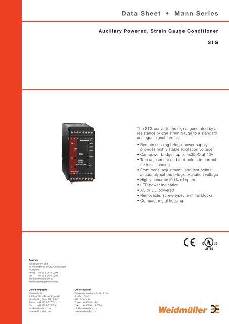
The <strong>STG</strong> converts the signal generated by a<br />
resistance bridge strain gauge to a standard<br />
analogue signal format.<br />
• Remote sensing bridge power supply<br />
provides highly stable excitation voltage<br />
• Can power bridges up to 4x350Ω at 10V<br />
• Tare adjustment and test points to correct<br />
for initial loading<br />
• Front panel adjustment and test points<br />
accurately set the bridge excitation voltage<br />
• Highly accurate (0.1% of span)<br />
• LED power indication<br />
• AC or DC powered<br />
• Removable, screw-type, terminal blocks<br />
• Compact metal housing<br />
% \<br />
Australia<br />
Weidmüller Pty Ltd.<br />
43 Huntingwood Drive, Huntingwood<br />
NSW 2148<br />
Phone +61 (0) 2 9671 9999<br />
Fax +61 (0) 2 9671 9900<br />
Info@weidmuller.com.au<br />
www.mannindustries.com.au<br />
United Kingdom<br />
Weidmüller Ltd.<br />
1 Abbey Wood Road, Kings Hill<br />
West Malling, Kent ME19 4YT<br />
Phone +44 1732-877032<br />
Fax +44 1732-873873<br />
Info@weidmuller.co.uk<br />
www.weidmueller.com<br />
Other countries<br />
Weidmüller Interface GmbH & Co.<br />
Postfach 3030<br />
32720 Detmold<br />
Phone +495231-14-0<br />
Fax +495231-14-2083<br />
info@weidmueller.com<br />
www.weidmueller.com
<strong>STG</strong> <strong>Strain</strong> <strong>Gauge</strong> Conditioner<br />
General Technical Data<br />
Input<br />
Type<br />
Resistance bridge strain gauge<br />
Input span ranges<br />
1mV to 700mV<br />
Input impedance<br />
1MΩ<br />
Bridge excitation voltage<br />
Type<br />
Remote sensing<br />
Excitation voltage<br />
5V or 10V<br />
Ripple<br />
less than 10mV p/p at full load<br />
Drive capability<br />
120mA @ 10V<br />
(equivalent to 4 x 350Ω loadcells @ 10V)<br />
Output<br />
Type<br />
4-20mA, 0-20mA and 1-5V (selected by push-fi t jumpers)<br />
Current ranges<br />
0-20mA, 4-20mA into 0-1KΩ load<br />
Voltage ranges<br />
0-5Vdc, 0-10Vdc, 1-5Vdc (true voltage source to 20mA)<br />
Ripple<br />
< 20mV peak to peak at maximum load and span<br />
Power supply<br />
Type<br />
AC or DC powered (as ordered)<br />
AC<br />
110Vac at 47-63Hz (permissible range 100-132Vac)<br />
240Vac at 47-63Hz (permissible range 200-264Vac)<br />
DC<br />
24Vdc (permissible range 20-28Vdc)<br />
Power Usage<br />
AC 3VA or 3W at 24Vdc<br />
Adjustments<br />
Type<br />
20-turn potentiometers<br />
Span<br />
45-105% of nominal span<br />
Zero<br />
±10% of nominal span<br />
Tare<br />
±100% or 0-200% of input span<br />
Bridge excitation<br />
±10% of nominal voltage<br />
General<br />
Linearity<br />
Typically ±0.05% of span<br />
Repeatability<br />
±0.05% of span<br />
Temperature drift<br />
Typically 0.02% span/°C<br />
Long term drift<br />
0.1% per 10,000 hours<br />
Frequency response<br />
-3dB point = 5Hz, optional 1KHz<br />
Response time<br />
200 mS for 10-90% output change<br />
Insulation Co-ordination<br />
Ports<br />
Input & Output / Power Supply / Case<br />
Rated Insulation Voltage<br />
300Vrms<br />
Overvoltage Category<br />
III<br />
Impulse Withstand 4kV (1.2 / 50)<br />
Isolation<br />
2 kV (between ports)<br />
Environmental Conditions<br />
Operating temperature 0 to 60 °C<br />
Storage temperature –25 to +70 °C<br />
Pollution Degree 2<br />
Relative humidity<br />
10–90% (non–condensing)<br />
Housing<br />
Type<br />
Anodised Aluminium Enclosure with protective earth<br />
Dimensions<br />
See diagram<br />
Weight<br />
0.45Kg<br />
Connection type<br />
Plug in terminal blocks with screw connections<br />
Approvals Mark Standard<br />
<strong>STG</strong> (DC powered only) E256486 CAN/CSA C22.2 No. 1010.1:92<br />
\<br />
UL61010-1: 2004<br />
%<br />
LV Directive<br />
EMC<br />
EN50178:1998<br />
BS EN 61326:1998 + A2<br />
%<br />
\<br />
Connections<br />
Terminal Signal<br />
1 Sense −<br />
2 Sense +<br />
Bridge Excitation<br />
3 Excitation +<br />
Voltage<br />
4 Excitation −<br />
5<br />
Not Used<br />
6<br />
7 Signal +<br />
Input signal<br />
8 Signal −<br />
9 Not Used<br />
10 Neutral (−)<br />
Power Supply<br />
11 Live (+)<br />
12 Not Used<br />
13 Output +<br />
Output signal<br />
14 Output −<br />
15<br />
Not Used<br />
16<br />
Case Earthing is via a stud on lower side of case<br />
Note: only the power supply is isolated.<br />
Dimension drawing<br />
RIGHT HAND SIDE VIEW<br />
TOP VIEW<br />
Effective depth :<br />
120mm (Top Hat 35mm +/- 0.3, DIN 46277-3, EN 50022)<br />
125mm (G - Rail 32mm +/- 0.3, DIN 46277-1, EN 50035)<br />
To surface (including rail/mounting plate)<br />
Ordering Information<br />
Type<br />
(Model 1/2/3/4 - See key below)<br />
96 mm<br />
46 mm<br />
Cat. No.<br />
<strong>STG</strong> 10V/2mV/V/4-20mA/24Vdc 7940011671<br />
Note: For other ranges please specify <strong>STG</strong>/1/2/3/4 where:<br />
1 - Bridge excitation voltage<br />
2 - Bridge sensitivity<br />
3 - Output signal format<br />
4 - Power supply voltage<br />
Page 2 Subject to technical alterations without notice • Printed in Australia • 7940015659 • 10/2008