ROTAMASS Coriolis Mass-Flow Meter
ROTAMASS Coriolis Mass-Flow Meter
ROTAMASS Coriolis Mass-Flow Meter

You also want an ePaper? Increase the reach of your titles
YUMPU automatically turns print PDFs into web optimized ePapers that Google loves.
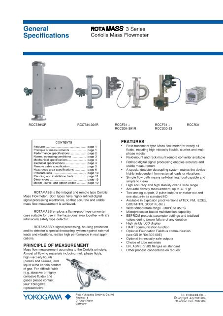
General<br />
Specifications<br />
3 Series<br />
<strong>Coriolis</strong> <strong>Mass</strong> <strong>Flow</strong>meter<br />
GS 01R4B04-00E-E<br />
RCCT39/XR RCCT34-39/IR RCCF31 + RCCF31 + RCCR31<br />
RCCS34-39/IR<br />
RCCS30-33<br />
CONTENTS<br />
Features ................................................ page 1<br />
Principle of measurements ................... page 1<br />
Performance specifications ................... page 2<br />
Normal operating conditions ................. page 3<br />
Mechanical specifications ..................... page 4<br />
Electrical specifications ......................... page 4<br />
Remote cable specification ................... page 5<br />
Hazardous area specifications .............. page 6<br />
Pressure loss ........................................ page 10<br />
Planning and installation hints ............... page 11<br />
Dimensions ........................................... page 13<br />
Model-, suffix- and option-codes ........... page 19<br />
<strong>ROTAMASS</strong> is the integral and remote type <strong>Coriolis</strong><br />
<strong>Mass</strong> <strong>Flow</strong>meter. Both types have highly refined digital<br />
signal processing electronics, so that accurate and stable<br />
mass flow measurement is achieved.<br />
<strong>ROTAMASS</strong> employs a flame-proof type converter<br />
case suitable for use in the hazardous area together with it´s<br />
intrinsically safety type detector.<br />
<strong>ROTAMASS</strong>´s signal processing, housing protection<br />
and its detector´s special decoupling system against external<br />
loads and vibrations, realize high performance in real applications.<br />
PRINCIPLE OF MEASUREMENT<br />
<strong>Mass</strong> flow measurement according to the <strong>Coriolis</strong> principle.<br />
Almost all flowing materials including multi phase fluids,<br />
high viscosity liquids<br />
(pastes and slurries) and<br />
liquid witha certain content<br />
of gas. For difficult fluids<br />
(e.g. abrasive or highly<br />
corrosive fluids) and<br />
gases please contact<br />
your Yokogawa<br />
representative.<br />
Rota Yokogawa GmbH & Co. KG<br />
Rheinstr. 8<br />
D-79664 Wehr<br />
Germany<br />
FEATURES<br />
• Field transmitter type <strong>Mass</strong> flow meter for nearly all<br />
fluids, including high viscosity liquids, slurries and multi<br />
phase media<br />
• Field-mount and rack-mount remote converter available<br />
• Refined digital signal processing enables accurate and<br />
stable measurement<br />
• A special detector decoupling system makes the device<br />
highly independent from external loads or vibrations.<br />
• Simple flow path means self-draining, food capable and<br />
simple to clean<br />
• High accuracy and high stability over a wide range<br />
• Accurate density measurement, up to +/- 1 g/l<br />
• Two analog outputs, 2 pulse outputs or status-out and<br />
one status-in as standard I/O<br />
• Available in explosion proof versions (ATEX, FM, IECEx,<br />
GOST/RTN, GOST K, etc.)<br />
• Wide temperature range –200°C to 350°C<br />
• Microprocessor-based multifunction capability<br />
• EEPROM protects parameter settings and totalized<br />
values during power failure of any duration<br />
• High visibly LCD display<br />
• HART communication function<br />
• Optional Foundation Fieldbus communication<br />
(see GS 01R04B05-00E)<br />
• Optional intrinsically safe outputs<br />
• Choice of tube materials<br />
• EN, ASME or JIS flanges as standard<br />
• Other process connections on request<br />
GS 01R04B04-00E-E<br />
©Copyright July 2003 (Rü)<br />
8th edition, Dec. 2007 (Rü)
PerfoRmance Specifications<br />
Model<br />
- Remote detector RCCS30 to 33 : 2 tubes, low flow design<br />
- Remote detector RCCS34 to 39/XR : 2 tube design<br />
- Remote field-mount converter RCCF31<br />
- Remote rack-mount converter RCCR31<br />
- Integral type RCCT34 to 39/XR : 2 tube integral design<br />
Fluid to be measured<br />
Measurement items<br />
<strong>Mass</strong> flow measurement<br />
Table 1: measuring range<br />
Type RCCS30 RCCS31 RCCS32 RCCS33<br />
Qmax t/h 0.1 0.3 0.6 1.5<br />
Qnom t/h 0.045 0.17 0.37 0.9<br />
T1a.EPS<br />
Type RCCS34 RCCS36 RCCS38 RCCS39 RCCS/T RCCS/T<br />
RCCT34 RCCT36 RCCT38 RCCT39 39 /IR 39 /XR<br />
Qmax t/h 5 15 50 120 300 600<br />
Qnom t/h 2.7 9 32 85 250 500<br />
Qnom is the water flow rate at about 1 bar pressure drop.<br />
The flowmeter has an automatically low cut at 0.05% of<br />
Qnom.<br />
Accuracy :<br />
Liquid :<br />
Gas (option /GA) :<br />
± 0.1% of measured value<br />
± zero stability (refer to table 2)<br />
± 0.5% of measured value<br />
± zero stability (refer to table 2)<br />
Accuracy based on the frequency output includes the combined<br />
effects of repeatability, linearity and hysteresis.<br />
GS 01R04B04-00E-E 8th edition Dec. 06, 2007 -00<br />
T1b.EPS<br />
Repeatability for liquids: ± 0.05%<br />
± ((zero stability/2) / flowrate*100%)<br />
Batch process :<br />
Error in %<br />
: Liquid, gas or slurries<br />
: <strong>Mass</strong> flow, density, temperature<br />
and derived from these values:<br />
concentration, volume flow and<br />
net flow<br />
above specified accuracy if the<br />
batch process is >1min. For<br />
shorter batch time (dt in s) the<br />
accuracy decreases with the<br />
square root of 60/dt<br />
1.0<br />
0.9<br />
0.8<br />
0.7<br />
0.6<br />
0.5<br />
0.4<br />
0.3<br />
0.2<br />
0.1<br />
-0.1 0<br />
-0.2<br />
-0.3<br />
-0.4<br />
-0.5<br />
-0.6<br />
-0.7<br />
-0.8<br />
-0.9<br />
-1.0<br />
0 50 100 150<br />
<strong>Flow</strong> in % of Qnom<br />
Table 2 : Zero Stability<br />
Type RCCS30 RCCS31 RCCS32 RCCS33<br />
kg/h 0.0025 0.0085 0.019 0.045<br />
T2a.EPS<br />
F10.EPS<br />
Type RCCS34 RCCS36 RCCS38 RCCS39<br />
RCCT34 RCCT36 RCCT38 RCCT39<br />
kg/h 0.135 0.45 1.6 4.3 13<br />
RCCS/T<br />
39 /IR<br />
RCCS/T<br />
39 /XR<br />
25<br />
T2b.EPS<br />
Pressure dependency<br />
The stiffness of the Rotamass tubes is slightly line pressure<br />
dependent. The static pressure effect of mass flow and density<br />
can be corrected by setting the static pressure manually via menu.<br />
RCCS30-RCCS34 : no relevant pressure effect<br />
Table 3 : Static pressure effect on mass flow (not corrected)<br />
Type RCCS36<br />
RCCT36<br />
RCCS38<br />
RCCT38<br />
% of rate SS -0.0033 -0.0085<br />
per bar HC -0.0049 -0.0126<br />
RCCS39<br />
RCCT39<br />
RCCS/T<br />
39 /IR<br />
-0.009 -0.0456<br />
-0.0133 -0.0675<br />
RCCS/T<br />
39 /XR<br />
-0.0169<br />
- - - -<br />
T3.EPS<br />
Density measurement<br />
Measuring range : 0.3 kg/l to 5 kg/l (RCCx39,<br />
RCCx39/IR and RCCx39/XR to 2 kg/l)<br />
No density measurement for gas application<br />
Accuracy (at calibration conditions)<br />
- RCCS30 : ± 8 g/l<br />
- RCCS31-33 : ± 4 g/l<br />
- RCCS/T34 : ± 3 g/l<br />
- RCCS/T36 : ± 2.2 g/l<br />
- RCCS/T38-39/XR : ± 1.5 g/l<br />
- RCCS/T34-39 : ± 1 g/l (with special calibration<br />
option /K3)<br />
- RCCS30-33 : ± 2 g/l (with special calibration<br />
option /K3, good thermal insulation of<br />
the detector or fixed temperature)<br />
Repeatability<br />
- RCCS32-33, RCCS/T34-39/XR : ± 0.33 g/l<br />
Temperature measurement<br />
Temperature measuring range of converter :<br />
Standard and with /MT : -200°C to 230°C<br />
With /HT : 0°C to 400°C<br />
Accuracy -100°C to 230°C : ± 0.5°C ± 0.5% of reading<br />
Accuracy others<br />
: ± 1°C ± 0.8% of reading<br />
For process temperatures more than 80°C higher/lower than<br />
ambient temperature the detector should be insulated to<br />
maintain optimum accuracy.<br />
Heating Tracing<br />
Heating with heat carrier, insulation and protection housing.<br />
The max. surface temperature at the protection housing from<br />
inner heating is 40°C. Above 150°C process temperature<br />
insulation from the manufacturer is recommended. However<br />
up to 230°C process temperature the customer can insulate<br />
the detector themselves.<br />
Option /T1 : only insulation and protection<br />
Option /T2 : insulation, protection and heating line<br />
Option /T3 : like /T2 but with ventilation<br />
Process connection for the heat carrier fluid (see table p. 17):<br />
for D-type flanges : EN DN15 PN40 Form B1<br />
for A-type flanges : ANSI ½ - 150 lbs.<br />
for J-type flanges : JIS DN15 10K<br />
Max. pressure : PN40<br />
Protection class : IP54, install roof protected<br />
For fluid temperatures below 0°C ask for special insulation<br />
(see also page 12).<br />
Calibration for liquids and gases :<br />
The <strong>ROTAMASS</strong> flow meters are factory calibrated with water.<br />
Calibration Conditions:<br />
- Water : 22.5°C ± 12.5°C<br />
- Ambient temperature : 22.5°C ± 12.5°C<br />
- Process Pressure : 1 to 2 bar abs<br />
For gas applications please choose option /GA.<br />
All specifications are based on above mentioned calibration<br />
reference conditions, a flow calibration protocol is attached to<br />
each instrument.<br />
All Rights Reserved. Copyright © 2003, Rota Yokogawa
Special calibrations<br />
- <strong>Mass</strong> flow with factory certificate (option /K2):<br />
Check at customer specified flow values acc.<br />
calibration order sheet<br />
- <strong>Mass</strong> flow with DKD certificate (option /K5):<br />
Calibration certificate of the DKD calibration<br />
laboratory of ROTA YOKOGAWA as part of the<br />
European Cooperation for Accreditation EA)<br />
Normal Operating Conditions<br />
Ambient temperature limits<br />
- Remote detector RCCS3 :<br />
Standard : -50°C to +80°C<br />
Option /HT<br />
: -50°C to +65°C<br />
(up to 280°C medium temp.)<br />
-50°C to +55°C<br />
(up to 350°C medium temp.)<br />
terminal box lower 100°C<br />
- Remote converter RCCF31, RCCR31 and Integral type<br />
RCCT3:<br />
Display work. range : -20°C to +55°C<br />
Electronic work. range : -40°C to +55°C<br />
Cold start :<br />
above -30°C<br />
Where meters are mounted in direct sunlight, it is<br />
recommended to install a sunshade. This is particularly<br />
important in countries with high ambient temperatures.<br />
Ambient humidity limits : 0 to 95% R.H.<br />
Process temperature limits<br />
Detector :<br />
- RCCS30 to 33 : -50°C to 150°C<br />
- RCCS34 to 39/XR : -180°C to 150°C<br />
- RCCS34 to 39/XR /MT : -180°C to 230°C<br />
(Range 150°C – 230°C<br />
recommended with /Tx option)<br />
- RCCS34 to 39/IR /HT : 0°C to 350°C (only with /Tx option)<br />
- On request : -200°C to 150°C<br />
Integral type :<br />
- RCCT34 to 39/XR : -40°C to 150°C<br />
Heat carrier fluid temperature limits<br />
(option /T2 or /T3 only for remote type RCCS30 to 39/IR)<br />
- Standard : 0°C to 150°C<br />
- With option /MT : 0°C to 230°C<br />
- With option /HT : 0°C to 350°C<br />
For temperature fluids below 0°C ask for special insulation<br />
(see also page 11).<br />
Process pressure limits<br />
According to the flange ratings:<br />
- EN PN 16 : max 16 bar<br />
- EN PN 40 : max 40 bar<br />
- EN PN 63 : max 63 bar<br />
- EN PN 100 : max 100 bar<br />
- ASME class 150 : max 16 bar<br />
- ASME class 300 : max 41 bar<br />
- ASME class 600 : max 83 bar<br />
- ASME class 900 : max 124 bar<br />
- ASME class 1500 : max 207 bar<br />
- JIS 10K : max. 14 bar (1.4 MPa)<br />
- JIS 20K : max. 34 bar (3.4 MPa)<br />
The RCCS30 to RCCS34 have also thread connection. For this<br />
connections the max. allowed tube pressure is the limitation.<br />
For all other standard process connection please find the<br />
max. process pressure in table 7.<br />
Maximum tube pressure for SL/SH up to 27°C (RT=Room<br />
Temp.):<br />
- RCCS30 / 31 / 32 : 285 bar<br />
- RCCS33 : 185 bar<br />
- RCCS34 / RCCT34 : 260 bar<br />
- RCCS36 / RCCT36 : 210 bar<br />
- RCCS38 / RCCT38 : 175 bar<br />
- RCCS39 / RCCT39 : 135 bar<br />
- RCCS39/IR / RCCT39/IR : 110 bar<br />
- RCCS39/XR / RCCT39/XR: 95 bar<br />
For higher medium temperatures maximum tube pressure<br />
needs to be derated as follows :<br />
up to 50 °C : 4% derating<br />
51 to 100 °C : 11% derating<br />
101 to 150 °C : 20% derating<br />
151 to 230 °C : 30% derating<br />
231 to 350 °C : 38% derating<br />
Higher pressure on request.<br />
The maximum process pressure of a single instrument is<br />
given by the lower value either of the process connections<br />
(table 7) or tubes. The maximum temperature and process<br />
pressure limits of an instrument are marked on the nameplate<br />
as TS and PS.<br />
Gas content limits for liquid/gas mixtures<br />
Gas content limit is defined as the amount of gas in a liquid/gas<br />
mixture which generates an error (frequency error) in<br />
the converter. The gas content limit is dependent on viscosity,<br />
surface tension and bubble size of the liquid/gas mixture.<br />
Furthermore it is highly flow rate dependent (the higher the<br />
flow rate, the lower the gas content limits). The stated values<br />
are for a flow of 50% of Qnom and water/air without /HP:<br />
- RCCS32 to 33 : no limitation<br />
- RCCS/T34 : no limitation<br />
- RCCS/T36 : approx. 50%<br />
- RCCS/T38 : approx. 30%<br />
- RCCS/T39 : approx. 7%<br />
- RCCS/T39/IR : approx. 3%<br />
- RCCS/T39/XR : approx. 2% (with option /HP)<br />
With option /HP the gas content limits are improved.<br />
With liquid/gas mixtures the specified mass flow accuracy will<br />
not be achieved.<br />
For short time aeration a function can be activated to keep<br />
the current outputs constant during the aeration time.<br />
Secondary containment<br />
Rupture pressure for RCCS/T34-38 is typical above 120bar,<br />
for RCCS/T39 above 80 bar, for RCCS/T39IR above 50bar.<br />
However if the detector housing is exposed to this pressure<br />
it will deform and measurement will be strongly influenced.<br />
Therefore the pressure test of the housing (option /J1)<br />
can only be done at the pressure where deformation does<br />
not happen. The housings of the sizes RCCS30-33 and<br />
RCCx39/XR can not withstand overpressure.<br />
2 phase flow, liquid/solid and liquid/liquid<br />
2 phase flow can generate minus span errors. The errors<br />
are proportional to the difference in density between the 2<br />
phases and the amount of the second phase. If the particles<br />
(or droplets) are very small no errors will be generated.<br />
Power supply and power consumption<br />
- AC-type : 90 to 264 V AC, 47-63 Hz<br />
For Ex version 250 V AC max.<br />
- DC-type : 20.5 to 28.8 V DC<br />
Consumption<br />
: max. 25VA / 10W<br />
All Rights Reserved. Copyright © 2003, Rota Yokogawa<br />
GS 01R04B04-00E-E 8th edition Dec. 06, 2007 -00
Mechanical Specifications<br />
Protection class<br />
- RCCT3x, RCCS3x, RCCF31<br />
: IP67<br />
- RCCR31 : IP20<br />
Materials<br />
- Detector housing : Stainless steel 304/1.4301<br />
- Detector terminal box : 316L/1.4404<br />
- Field- mount converter housing<br />
: Aluminium alloy with Polyurethane<br />
corrosion-resistant coating or<br />
epoxy coating (option /X1)<br />
- Rack- mount converter housing<br />
: Aluminium<br />
Coating colour<br />
- Field-mount converter case<br />
: Mint green<br />
Wetted parts<br />
- RCCS30 to 33 :<br />
Tubes<br />
: HC-22/2.4602<br />
Process connections : 316L/1.4404<br />
- RCCx34 to 39/IR :<br />
Tubes and process connection<br />
: 316L/1.4404 or<br />
Hastelloy C-22/2.4602<br />
- RCCx39/XR :<br />
Tubes and process connection<br />
: 316L/1.4404<br />
Table 4 : Diameter of measuring tubes<br />
Type RCCS30 RCCS31 RCCS32 RCCS33<br />
Inner diameter mm 1.2 2.1 3 4.5<br />
Wall thickness mm 0.2 0.25 0.25 0.25<br />
T5a.EPS<br />
Type<br />
RCCS34 RCCS36 RCCS38 RCCS39 RCCS39/IR RCCS39/XR<br />
RCCT34 RCCT36 RCCT38 RCCT39 RCCT39/IR RCCT39/XR<br />
Inner diameter mm 7.6 13.4 22.1 37.2 55.1 82.5<br />
Wall thickness mm 0.91 1.24 1.65 2.6 2.6<br />
Pressure Equipment Directive 97/23/EC<br />
- Module : H; Fluid group : 1; Category : III<br />
RCCx34-RCCx38 : Fluid group 2, SEP<br />
RCCx39-RCCx39/XR : Fluid group 2, Cat. I<br />
For ASME Flanges : CRN 0F10715.5<br />
3.2<br />
T5b.EPS<br />
Electrical Specifications<br />
Power supply<br />
- AC- type : 90 V to 264 V<br />
90 V to 250 V for Ex-type<br />
- DC- type : 20.5 V to 28.8 V<br />
External circuit breaker rating : 5 A, 250 V (In the converter<br />
no power switch is installed).<br />
Fuse on Base Board :<br />
- AC- type : 2 A, T, breaking capacity 1500A<br />
- DC- type : 2 A, T, breaking capacity 1500A<br />
I/O signals<br />
- Two current outputs:<br />
4 to 20 mA DC, galvanic separated from other signals,<br />
Load resistance : 20 Ω to 600 Ω<br />
Failure current according NAMUR NE43<br />
Ambient temperature effect : < 0.05% of span/10°C<br />
Linearity<br />
: 0.008 mA = 0.05% of span<br />
Setting range URV for liquids: 5 to100% of Qnom<br />
Setting range URV for gases: 1 to 100% of Qnom<br />
- Two Pulse outputs / status outputs :<br />
passive Transistor contact output , 30 V DC, 200mA<br />
Output rate :<br />
Output 1<br />
: 0 to 10000 pulses/s<br />
Output 2<br />
: 0 to 2000 pulses/s<br />
Option /NM : passive, according EN 60947-5-6<br />
Option /AP:active output, 12V,6 mA,R L<br />
> 10 kΩ<br />
Active pulse output is not isolated from current output 2<br />
As frequency output :<br />
Output 1<br />
: 20Hz to10000Hz<br />
Output 2<br />
: 20Hz to 2000Hz<br />
- Status input : Voltage-free contact<br />
Closed<br />
: < 200Ω<br />
Open<br />
: > 100 kΩ<br />
Intrinsic safe outputs (/KF2), a total of 2 outputs<br />
- One passive current output (additional power supply<br />
needed) :<br />
4 to 20 mA DC, galvanic separated from other signals.<br />
Supply voltage 10.5V to 30V DC(without HART), 165mA<br />
Supply voltage 16.75V to 30V DC (with HART), 165mA.<br />
Load resistance : 20Ω ... 600Ω<br />
Ambient temperature effect : < 0.05% of span/10°C<br />
- One pulse output / status output :<br />
passive Transistor contact output, 30 V DC, 100 mA<br />
Output rate<br />
: 0 to 2000 pulses/s<br />
As frequency output : 20Hz to 2000Hz<br />
Option /NM : passive, according EN 60947-5-6<br />
Digital communication<br />
- HART communication signal, superimposed on 4 -20 mA<br />
DC signal (Iout1)<br />
- Load resistance : 230Ω to 600 Ω (including cable)<br />
- Power line spacing : >15 cm, avoid parallel wiring<br />
- Cable length : ≤ 2 km if „CEV” cables are used<br />
- Foundation Fieldbus communication (/FB)<br />
- see GS 01R04B05-00E<br />
Setting functions<br />
Parameter setting is possible by using the switches on<br />
the display or with HART communication.<br />
Display function<br />
- Up to 4 lines.<br />
- 3 languages selectable (English, German, French)<br />
- Instantaneous flow rate, density, temperature or<br />
totalized flow can be displayed.<br />
Damping functions<br />
Settable from 0.1 seconds (63% response time) to 200<br />
seconds, controls display and outputs.<br />
GS 01R04B04-00E-E 8th edition Dec. 06, 2007 -00<br />
All Rights Reserved. Copyright © 2003, Rota Yokogawa
Isolation resistance of converter<br />
When surge arrestors are removed<br />
- between power and ground terminal: 100 MΩ / 500 V DC<br />
- between power and I/O terminals : 20 MΩ / 100 V DC<br />
- between I/O terminals and ground : 20 MΩ / 100 V DC<br />
Dielectric strength<br />
When surge arrestors are removed<br />
- between power and ground terminal : 1,500 V AC for 1 minute<br />
Lightning Protection<br />
Arresters (2000A) are inside converter for power supply<br />
lines.<br />
Remote Cable RCCY03 Specification<br />
Li2Y(St)/CY 3x2 AWG24 + 1x3 AWG20 or<br />
Li2Y(St)/CY 6x2 AWG24<br />
pair/triple shielded; pair/triple twisted; overall shielding<br />
RCCY033/034 and RCCY031/032/KS1: flame propagation<br />
acc. IEC 60332-1.<br />
Model code<br />
Temperature<br />
range<br />
Wire gauge<br />
Resistance<br />
of loop<br />
Capacitance<br />
wire/wire<br />
Capacitance<br />
wire/shield<br />
Inductance<br />
wire/wire<br />
RCCY031/32 -50 to +70 °C<br />
AWG 24<br />
AWG 20<br />
190 Ω/km<br />
70 Ω/km<br />
157 nF/km<br />
193 nF/km<br />
249 nF/km<br />
290 nF/km<br />
0.6 mH/km<br />
0.65 mH/km<br />
RCCY031/32<br />
/KS1<br />
-50 to +70 °C<br />
RCCY033/34 -30 to +105 °C<br />
AWG 24<br />
AWG 20<br />
AWG 24<br />
AWG 20<br />
190 Ω/km<br />
70 Ω/km<br />
177 Ω/km<br />
70 Ω/km<br />
157 nF/km<br />
193 nF/km<br />
175 nF/km<br />
145 nF/km<br />
249 nF/km<br />
290 nF/km<br />
350 nF/km<br />
290 nF/km<br />
0.6 mH/km<br />
0.65 mH/km<br />
0.8 mH/km<br />
0.7 mH/km<br />
RCCY033/34<br />
/KS1<br />
-30 to +105 °C AWG 24 180 Ω/km 190 nF/km 118 nF/km 0.6 mH/km<br />
AWG 20 wires are used for temperature measurement circuit.<br />
All Rights Reserved. Copyright © 2003, Rota Yokogawa<br />
GS 01R04B04-00E-E 8th edition Dec. 06, 2007 -00
hazardous area specifications<br />
ATEX<br />
Remote detector RCCS30 ... 39/XR (option /KS1):<br />
- KEMA 01ATEX 1075 X<br />
- Intrinsically safe<br />
- II 2G Ex ib IIB/IIC T1 ... T6<br />
- II 2D Ex ibD 21 IP6x Txxx (xxx = max. surface<br />
temperature see below)<br />
- Max. surface temperature :<br />
Standard : 150°C<br />
/MT : 220°C<br />
/HT : 350°C<br />
- Degree of protection : IP67<br />
- Ambient humidity : 0 to 95% RH<br />
- Ambient temperature range<br />
Standard and option /MT<br />
: –50°C to +80°C<br />
Option /HT (process temperature < 280°C<br />
: –50°C to +65°C<br />
Option /HT (process temperature < 350°C<br />
: –50°C to +55°C<br />
- Process temperature limits :<br />
Standard : -50°C to 150°C<br />
Option /MT: : -50°C to 220°C<br />
Option /HT : 0°C to 350°C<br />
- Heat carrier fluid temperature limits<br />
Standard : -50°C to 150°C<br />
Option /MT: : -50°C to 220°C<br />
Option /HT : 0°C to 350°C<br />
Remote converter RCCF31 (option /KF1) :<br />
- KEMA 02ATEX 2183 X<br />
- Flame proof with intrinsic safe connection to detector (ib)<br />
- II 2G Ex d(e) [ib] IIC T6<br />
- II 2G Ex d(e) [ib] IIB T6 with option /HP<br />
- II 2D Ex tD [ibD] A21 IP6x T70°C<br />
- Max. surface temperature : 70°C<br />
- Degree of protection : IP67<br />
- Power supply : 90 to 250V AC, 50/60 Hz or<br />
20.5 to 28.8V DC<br />
- Power consumption : max. 25VA / 10W<br />
- Ambient humidity : 0 to 95% RH<br />
- Ambient temperature range : -20°C to +50°C<br />
Remote converter RCCF31 (option /KF2) :<br />
- KEMA 02ATEX 2183 X<br />
- Flame proof with intrinsic safe connection to detector (ib)<br />
- Additional intrinsic safe outputs.<br />
- II 2G Ex d(e) [ia] [ib] IIC T6<br />
- II 2G Ex d(e) [ia] [ib] IIB T6 with option /HP<br />
Protection [ia] refers to the intrinsic safe outputs.<br />
Protection [ib] refers to the connection to the detector.<br />
- II 2D Ex tD [ibD] A21 IP6x T70°C<br />
- Max. surface temperature : 70°C<br />
- Degree of protection : IP67<br />
- Power supply : 90 to 250V AC, 50/60 Hz or<br />
20.5 to 28.8V DC<br />
- Power consumption : max. 25VA / 10W<br />
- Ambient humidity : 0 to 95% RH<br />
- Ambient temperature range : -20°C to +50°C<br />
Remote converter RCCR31 (option /KS1) :<br />
- KEMA 02ATEX 2183 X<br />
- Associated apparatus with intrinsic safe connection to<br />
detector (ib)<br />
- II (2)G [Ex ib] IIC<br />
- II (2)G [Ex ib] IIB with option /HP<br />
- II (2)D [Ex ibD]<br />
- Power supply : 90 to 250V AC, 50/60 Hz or<br />
20.5 to 28.8V DC<br />
- Power consumption : max. 25VA / 10W<br />
- Ambient humidity : 0 to 95% RH<br />
- Ambient temperature range : -20°C to +50°C<br />
GS 01R04B04-00E-E 8th edition Dec. 06, 2007 -00<br />
WARNING<br />
Remote rack-mount converter RCCR31 must be installed in<br />
safe area !<br />
Integral type RCCT34 ... 39/XR (option /KF1) :<br />
- KEMA 02ATEX 2183 X<br />
- Flame proof with intrinsic safe connection to detector (ib)<br />
- II 2G Ex d(e) [ib] IIC T6 ... T3<br />
- II 2G Ex d(e) [ib] IIB T6 ... T3 with option /HP<br />
- II 2D Ex tD A21 IP6x T150°C<br />
- Max. surface temperature : 150°C<br />
- Degree of protection : IP67<br />
- Power supply : 90 to 250V AC, 50/60 Hz or<br />
20.5 to 28.8V DC<br />
- Power consumption : max. 25VA / 10W<br />
- Ambient humidity : 0 to 95% RH<br />
- Ambient temperature range : −20°C to +50°C<br />
Integral type RCCT34 ... 39/XR (option /KF2) :<br />
- KEMA 02ATEX 2183 X<br />
- Flame proof with intrinsic safe connection to detector (ib)<br />
- Additional intrinsic safe outputs.<br />
- II 2G Ex d(e) [ia] [ib] IIC T6 ... T3<br />
- II 2G Ex d(e) [ia] [ib] IIB T6 ... T3 with option /HP<br />
Protection [ia] refers to the intrinsic safe outputs.<br />
Protection [ib] refers to the connection to the detector.<br />
- II 2D Ex tD A21 IP6x T150°C<br />
- Max. surface temperature : 150°C<br />
- Degree of protection : IP67<br />
- Power supply : 90 to 250V AC, 50/60 Hz or<br />
20.5 to 28.8V DC<br />
- Power consumption : max. 25VA / 10W<br />
- Ambient humidity : 0 to 95% RH<br />
- Ambient temperature range : −20°C to +50°C<br />
Electrical data Remote detector RCCS30 ... 33 :<br />
- Driving circuit : terminals D+ and D<br />
Ex ib IIC : Ui = 16 V; Ii = 53 mA; Pi = 0.212 W<br />
Li = 4.2mH; Ci = negligible small<br />
Ex ib IIB : Ui = 16 V; Ii = 153 mA; Pi = 0.612 W<br />
Li = 4.2mH; Ci = negligible small<br />
- Sensor circuits: terminals S1+ and S1- or S2+ and S2-<br />
Ex ib IIC : Ui = 16V; Ii = 80mA; Pi = 0.32 W<br />
Li = 4.2mH; Ci = negligible small<br />
- Temperature sensor circuit : terminals TP1, TP2, TP3<br />
Ex ib IIC : Ui = 16V; Ii = 50mA; Pi = 0.2 W<br />
Li = negligible small; Ci = negligible small<br />
Electrical data Remote detector RCCS34 ... 39/XR :<br />
- Driving circuit : terminals D+ and D<br />
Ex ib IIC : Ui = 16 V; Ii = 53 mA; Pi = 0.212 W<br />
Li = 3.2mH; Ci = negligible small<br />
Ex ib IIB : Ui = 16 V; Ii = 153 mA; Pi = 0.612 W<br />
Li = 3.2mH; Ci = negligible small<br />
- Sensor circuits: terminals S1+ and S1- or S2+ and S2-<br />
Ex ib IIC : Ui = 16V; Ii = 80mA; Pi = 0.32 W<br />
Li = 2.1mH; Ci = negligible small<br />
- Temperature sensor circuit : terminals TP1, TP2, TP3<br />
Ex ib IIC : Ui = 16V; Ii =50mA; Pi = 0.2 W<br />
Li = negligible small; Ci = negligible small<br />
Electrical data Remote converter RCCF31, RCCR31 and<br />
converter of Intergral type RCCT3 :<br />
- Driving circuit : terminals D+ / D-<br />
Ex [ib] IIC : Uo = 14.5 V; Io = 47 mA; Po = 0.171 W<br />
Lo = 15mH; Co = 0.65µF<br />
Ex [ib] IIB : Uo = 11.7 V; Io = 124 mA; Po = 0.363 W<br />
Lo = 8mH; Co = 10.3µF<br />
- Sensor circuits: terminals S1+/ S1- or S2+ / S2-<br />
Ex [ib] IIB/IIC :Uo = 14.5V; Io = 47mA; Po = 0.171 W<br />
Ex [ib] IIC : Lo = 15mH; Co = 0.65µF<br />
Ex [ib] IIB : Lo = 60mH; Co = 4.07µF<br />
All Rights Reserved. Copyright © 2003, Rota Yokogawa
- Temperature sensor circuit : terminals TP1, TP2, TP3<br />
Ex [ib] IIB/IIC : Uo = 13.3V; Io =40mA; Po = 0.133 W<br />
Ex [ib] IIC : Lo = 20mH; Co =0.91µF<br />
Ex [ib] IIB : Lo = 80mH; Co =5.6µF<br />
- Current output (only option /KF2) :<br />
Ex [ia] IIC : Ui = 30 V; Ii = 165 mA; Pi = 1.25 W<br />
Li = negligible small; Ci = 6.9nF<br />
- Pulse output (only option /KF2) :<br />
Ex [ia] IIC : Ui = 30 V; Ii = 100 mA; Pi = 0.75 W<br />
Li = negligible small; Ci = 4.5nF<br />
Temperature classification see table 5.<br />
INMETRO approval (For Brazil)<br />
RCCS3x with option /US1.<br />
RCCT3x with options /UF1 ... /UF2 same as ATEX /KF1 ...<br />
/KF2<br />
RCCF31 with options /UF1 ... /UF2 same as ATEX /KF1 ...<br />
/KF2<br />
RCCR31 with option /US1 same as ATEX /KS1<br />
Same parameters and specifications as ATEX approval.<br />
FM (For USA and Canada)<br />
Remote detector RCCS30 ... 39/XR (option /FS1) :<br />
- Intrinsically safe<br />
- AEx ia IIC, Class 1, Zone 0<br />
- IS Class I, Division 1, Groups A,B,C,D T6<br />
- DIP Class II / III, Division 1, Groups E,F,G<br />
- IP67 / NEMA 4X<br />
Remote converter RCCF31 (option /FF1) :<br />
- Housing explosion proof<br />
- Provides intrinsically safe detector circuits<br />
- AEx d [ia] IIC, Class I, Zone 1, T6<br />
- AEx d [ia] IIB, Class I, Zone 1, T6 with option /HP<br />
- Class I, Division 1, Groups A,B,C,D<br />
- Class I, Division 1, Groups C,D with option /HP<br />
- Class II / III, Division 1, Groups E,F,G<br />
- AIS Class I / II / III, Division 1, Groups A,B,C,D,E,F,G<br />
- AIS Class I / II / III, Division 1, Groups C,D,E,F,G with /HP<br />
- IP67 / NEMA 4X<br />
Remote converter RCCR31 (option /FS1) :<br />
- Intrinsic safe associated apparatus<br />
- Provides intrinsically safe detector circuits<br />
- [AEx ia] IIC, Class I, Zone 1<br />
- [AEx ia] IIB, Class I, Zone 1, T6 with option /HP<br />
- AIS Class I, Division 1, Groups A,B,C,D<br />
- AIS Class I, Division 1, Groups C,D with option /HP<br />
Integral type RCCT34 ... 39/XR (option /FF1) :<br />
- Housing explosion proof<br />
- AEx d [ia] IIC, Class I, Zone 1, T6<br />
- AEx d [ia] IIB, Class I, Zone 1, T6 with option /HP<br />
- Class I, Division 1, Groups A,B,C,D<br />
- Class I, Division 1, Groups C,D with option /HP<br />
- Class II / III, Division 1, Groups E,F,G<br />
- IP67 / NEMA 4X<br />
Electrical data Remote converter RCCF31, RCCR31 and<br />
converter of Intergral type RCCT3 :<br />
- Driving circuit : terminals D+ / D-<br />
Uo = 14.5 V; Io = 47 mA; Po = 0.171 W<br />
Lo = 15 mH; Co = 0.65 µF<br />
- Driving circuit : terminals D+ / D- with option /HP<br />
Uo = 11.7 V; Io = 124 mA; Po = 0.363 W<br />
Lo = 8 mH; Co = 10.3 µF<br />
- Sensor circuits: terminals S1+/ S1- or S2+ / S2-<br />
Uo = 14.5V; Io = 47mA; Po = 0.363 W<br />
Lo = 15 mH; Co = 0.65 µF<br />
- Temperature sensor circuit : terminals TP1,TP2, TP3<br />
Uo = 13.3V; Io =40mA; Po = 0.133 W<br />
Lo = 20 mH; Co =0.91 µF<br />
Electrical data Remote detector RCCS30 ... 33 :<br />
- Driving circuit : terminals D+ and D<br />
Groups A-D: Ui = 16 V; Ii = 53 mA; Pi = 0.212 W<br />
Li = 4.2mH; Ci = negligible small<br />
Groups C,D: Ui = 16 V; Ii = 153 mA; Pi = 0.612 W<br />
Li = 4.2mH; Ci = negligible small<br />
- Sensor circuits: terminals S1+ and S1- or S2+ and S2-<br />
Ui = 16V; Ii = 80mA; Pi = 0.32 W<br />
Li = 4.2mH; Ci = negligible small<br />
- Temperature sensor circuit : terminals TP1, TP2, TP3<br />
Ui = 16V; Ii =50mA; Pi = 0.2 W<br />
Li = negligible small; Ci = negligible small<br />
Electrical data Remote detector RCCS34 ... 39/XR :<br />
- Driving circuit : terminals D+ and D<br />
Groups A-D: Ui = 16 V; Ii = 53 mA; Pi = 0.212 W<br />
Li = 3.2mH; Ci = negligible small<br />
Groups C,D: Ui = 16 V; Ii = 153 mA; Pi = 0.612 W<br />
Li = 3.2mH; Ci = negligible small<br />
- Sensor circuits: terminals S1+ and S1- or S2+ and S2-<br />
Ui = 16V; Ii = 80mA; Pi = 0.32 W<br />
Li = 2.1mH; Ci = negligible small<br />
- Temperature sensor circuit : terminals TP1, TP2, TP3<br />
Ui = 16V; Ii =50mA; Pi = 0.2 W<br />
Li = negligible small; Ci = negligible small<br />
The remote converter RCCF31 has a T6 temperature class<br />
rating for operation at ambient temperature up to +50°C / +122°F.<br />
Special conditions :<br />
- Rotamass with FM approval is only avalable with ANSI<br />
1/2” NPT cable conduit connection “A”.<br />
- The flowmeter must be connected to the potential<br />
equalization system.<br />
- For AC-version maximum power supply is 250V AC.<br />
- For remote type the maximum cable length is 50m / 164ft.<br />
- For remote type at ambient temperature up to 50°C / 122°F<br />
use remote cable RCCY031 or RCCY032.<br />
- For remote type at ambient temperature from 50°C /<br />
122°F up to 80°C / 176°F use remote cable RCCY033 or<br />
RCCY034.<br />
- Use conduit seals within 18 inches for power supply- and<br />
IO- cable entries at RCCT3 / RCCF31.<br />
Process temperature limits :<br />
- Standard : -50°C to 150°C / -58°F to 302°F<br />
- with option /MT : -50°C to 220°C / -58°F to 428°F<br />
- with option /HT : 0°C to 350°C / 32°F to 662°F<br />
Heat carrier fluid temperature limits :<br />
- Standard : -50°C to 150°C / -58°F to 302°F<br />
- with option /MT : -50°C to 220°C / -58°F to 428°F<br />
- with option /HT : 0°C to 350°C / 32°F to 662°F<br />
All Rights Reserved. Copyright © 2003, Rota Yokogawa<br />
GS 01R04B04-00E-E 8th edition Dec. 06, 2007 -00
GOST approval<br />
Rota Yokogawa has the “Pattern Approval Certificate of Measuring<br />
Instruments” which allows to export the instrument to<br />
Russia, Kazachstan and other CIS countries. Furthermore<br />
Rotamass is RTN (GGTN) approved for installation in hazardous<br />
areas. For the export of Rotamass to CIS countries<br />
please contact your Yokogawa representative<br />
IECEx approval<br />
Certificate: IECEx KEM 06.0031X<br />
Remote detector RCCS30 ... 39/XR (option /ES1):<br />
- Intrinsically safe<br />
- II 2G Ex ib IIB/IIC T6<br />
- Standard : Ex ibD 21 IP6x T150°C<br />
Option /MT : Ex ibD 21 IP6x T220°C<br />
Option /HT : Ex ibD 21 IP6x T350°C<br />
- Max. surface temperature :<br />
Standard : 150°C<br />
/MT : 220°C<br />
/HT : 350°C<br />
- Degree of protection : IP67<br />
- Ambient humidity : 0 to 95% RH<br />
- Ambient temperature range<br />
Standard and option /MT<br />
: –50°C to +80°C<br />
Option /HT (process temperature < 280°C<br />
: –50°C to +65°C<br />
Option /HT (process temperature < 350°C<br />
: –50°C to +55°C<br />
- Process temperature limits :<br />
Standard : -50°C to 150°C<br />
Option /MT: : -50°C to 220°C<br />
Option /HT : 0°C to 350°C<br />
- Heat carrier fluid temperature limits :<br />
Standard : -50°C to 150°C<br />
Option /MT: : -50°C to 220°C<br />
Option /HT : 0°C to 350°C<br />
Remote converter RCCF31 (option /EF1) :<br />
- Explosion proof with intrinsic safe connection to detector (ib)<br />
- II 2G Ex d(e) [ib] IIC T6<br />
- II 2G Ex d(e) [ib] IIB T6 with option /HP<br />
- II 2D Ex tD [ibD] A21 IP6x T70°C<br />
- Max. surface temperature : 70°C<br />
- Degree of protection : IP67<br />
- Power supply : 90 to 250V AC, 50/60 Hz or<br />
20.5 to 28.8V DC<br />
- Power consumption : max. 25VA / 10W<br />
- Ambient humidity : 0 to 95% RH<br />
- Ambient temperature range : -20°C to +50°C<br />
Remote converter RCCF31 (option /EF2) :<br />
- KEMA 02ATEX 2183 X<br />
- Explosion proof with intrinsic safe connection to detector (ib)<br />
- Additional intrinsic safe outputs.<br />
- II 2G Ex d(e) [ia] [ib] IIC T6<br />
- II 2G Ex d(e) [ia] [ib] IIB T6 with option /HP<br />
Protection [ia] refers to the intrinsic safe outputs.<br />
Protection [ib] refers to the connection to the detector.<br />
- II 2D Ex tD [ibD] A21 IP6x T70°C<br />
- Max. surface temperature : 70°C<br />
- Degree of protection : IP67<br />
- Power supply : 90 to 250V AC, 50/60 Hz or<br />
20.5 to 28.8V DC<br />
- Power consumption : max. 25VA / 10W<br />
- Ambient humidity : 0 to 95% RH<br />
- Ambient temperature range : -20°C to +50°C<br />
Remote converter RCCR31 (option /ES1) :<br />
- Associated apparatus with intrinsic safe connection to<br />
detector (ib)<br />
- II (2)G [Ex ib] IIC<br />
- II (2)G [Ex ib] IIB with option /HP<br />
- II (2)D [Ex ibD]<br />
- Power supply : 90 to 250V AC, 50/60 Hz or<br />
20.5 to 28.8V DC<br />
- Power consumption : max. 25VA / 10W<br />
- Ambient humidity : 0 to 95% RH<br />
- Ambient temperature range : -20°C to +50°C<br />
WARNING<br />
Remote rack-mount converter RCCR31 must be installed in<br />
safe area !<br />
Integral type RCCT34 ... 39/XR (option /EF1) :<br />
- Explosion proof with intrinsic safe connection to detector (ib)<br />
- II 2G Ex d(e) [ib] IIC T6 ... T3<br />
- II 2G Ex d(e) [ib] IIB T6 ... T3 with option /HP<br />
- II 2D Ex tD A21 IP6x T150°C<br />
- Max. surface temperature : 150°C<br />
- Degree of protection : IP67<br />
- Power supply : 90 to 250V AC, 50/60 Hz or<br />
20.5 to 28.8V DC<br />
- Power consumption : max. 25VA / 10W<br />
- Ambient humidity : 0 to 95% RH<br />
- Ambient temperature range : −20°C to +50°C<br />
Integral type RCCT34 ... 39/XR (option /EF2) :<br />
- Flame proof with intrinsic safe connection to detector (ib)<br />
- Additional intrinsic safe outputs.<br />
- II 2G Ex d(e) [ia] [ib] IIC T6 ... T3<br />
- II 2G Ex d(e) [ia] [ib] IIB T6 ... T3 with option /HP<br />
Protection [ia] refers to the intrinsic safe outputs.<br />
Protection [ib] refers to the connection to the detector.<br />
- II 2D Ex tD A21 IP6x T150°C<br />
- Max. surface temperature : 150°C<br />
- Degree of protection : IP67<br />
- Power supply : 90 to 250V AC, 50/60 Hz or<br />
20.5 to 28.8V DC<br />
- Power consumption : max. 25VA / 10W<br />
- Ambient humidity : 0 to 95% RH<br />
- Ambient temperature range : −20°C to +50°C<br />
Electrical data Remote converter RCCF31, RCCR31 and<br />
converter of Intergral type RCCT3 :<br />
- Driving circuit : terminals D+ / D-<br />
Ex [ib] IIC : Uo = 14.5 V; Io = 47 mA; Po = 0.171 W<br />
Lo = 15mH; Co = 0.65µF<br />
Ex [ib] IIB : Uo = 11.7 V; Io = 124 mA; Po = 0.363 W<br />
Lo = 8mH; Co = 10.3µF<br />
- Sensor circuits: terminals S1+/ S1- or S2+ / S2-<br />
Ex [ib] IIB/IIC : Uo = 14.5V; Io = 47mA; Po = 0.171 W<br />
Ex [ib] IIC : Lo = 15mH; Co = 0.65µF<br />
Ex [ib] IIB : Lo = 60mH; Co = 4.07µF<br />
- Temperature sensor circuit : terminals TP1, TP2, TP3<br />
Ex [ib] IIB/IIC : Uo = 13.3V; Io =40mA; Po = 0.133 W<br />
Ex [ib] IIC : Lo = 20mH; Co =0.91µF<br />
Ex [ib] IIB : Lo = 80mH; Co =5.6µF<br />
- Current output (only option /KF2) :<br />
Ex [ia] IIC :<br />
- Pulse output (only option /KF2) :<br />
Ex [ia] IIC :<br />
Ui = 30 V; Ii = 165 mA; Pi = 1.25 W<br />
Li = negligible small; Ci = 6.9nF<br />
Ui = 30 V; Ii = 100 mA; Pi = 0.75 W<br />
Li = negligible small; Ci = 4.5nF<br />
GS 01R04B04-00E-E 8th edition Dec. 06, 2007 -00<br />
All Rights Reserved. Copyright © 2003, Rota Yokogawa
Electrical data Remote detector RCCS30 ... 33:<br />
- Driving circuit : terminals D+ / D-<br />
Ex ib IIC : Ui = 16 V; Ii = 53 mA; Pi = 0.212 W<br />
Li = 4.2mH; Ci = negligible small<br />
Ex ib IIB : Ui = 16 V; Ii = 153 mA; Pi = 0.612 W<br />
Li = 4.2mH; Ci = negligible small<br />
- Sensor circuits: terminals S1+/ S1- or S2+ / S2-<br />
Ex ib IIC : Ui = 16V; Ii = 80mA; Pi = 0.32 W<br />
Li = 4.2mH; Ci = negligible small<br />
- Temperature sensor circuit : terminals TP1,TP2,TP3<br />
Ex ib IIC : Ui = 16V; Ii = 50mA; Pi = 0.2 W<br />
Li = negligible small;<br />
Ci = negligible small<br />
Electrical data Remote detector RCCS34 ... 39/XR:<br />
- Driving circuit : terminals D+ / D<br />
Ex ib IIC : Ui = 16 V; Ii = 53 mA; Pi = 0.212 W<br />
Li = 3.2mH; Ci = negligible small<br />
Ex ib IIB : Ui = 16 V; Ii = 153 mA; Pi = 0.612 W<br />
Li = 3.2mH; Ci = negligible small<br />
- Sensor circuits: terminals S1+/ S1- or S2+ / S2-<br />
Ex ib IIC : Ui = 16V; Ii = 80mA; Pi = 0.32 W<br />
Li = 2.1mH; Ci = negligible small<br />
- Temperature sensor circuit : terminals TP1,TP2,TP3<br />
Ex ib IIC : Ui = 16V; Ii = 50mA; Pi = 0.2 W<br />
Li = negligible small;<br />
Ci = negligible small<br />
Table 5 : Temperature classification for ATEX,FM, IECEx and INMETRO certified flowmeters<br />
Temp.<br />
class<br />
RCCS30 to RCCS33<br />
Max.<br />
ambient<br />
temperature<br />
Max.<br />
medium<br />
temperature<br />
RCCS34 to RCCS39/XR<br />
without insulation<br />
Max.<br />
ambient<br />
temperature<br />
Max.<br />
medium<br />
temperature /<br />
temperature of<br />
heat carrier<br />
T6 ≤ 50°C / 122°F ≤ 60°C / 140°F ≤ 40°C / 104°F ≤ 40°C / 104°F<br />
T5 ≤ 50°C / 122°F ≤ 80°C / 176°F ≤ 55°C / 131°F ≤ 55°C / 131°F<br />
T4<br />
≤ 80°C / 176°F ≤ 100°C / 212°F ≤ 80°C / 176°F ≤ 100°C / 212°F<br />
≤ 50°C / 122°F ≤ 120°C / 248°F ≤ 40°C / 104°F ≤ 120°C / 248°F<br />
T3 ≤ 80°C / 176°F ≤ 150°C / 302°F ≤ 80°C / 176°F ≤ 160°C / 320°F<br />
≤ 40°C / 104°F ≤ 180°C / 356°F<br />
T2 ≤ 80°C / 176°F ≤ 150°C / 302°F ≤ 80°C / 176°F ≤ 220°C / 428°F<br />
T1<br />
For customer insulation of RCCS34 to 39/XR see instruction manual.<br />
RCCS34 to RCCS39/IR<br />
with factory insulation /T1.../T3<br />
Max.<br />
ambient<br />
temperature<br />
Max.<br />
medium<br />
temperature /<br />
temperature of<br />
heat carrier<br />
≤ 65°C / 149°F ≤ 65°C / 149°F<br />
≤ 75°C / 167°F ≤ 75°C / 167°F<br />
≤ 70°C / 158°F ≤ 115°C / 239°F<br />
≤ 70°C / 158°F ≤ 180°C / 356°F<br />
≤ 65°C / 149°F ≤ 275°C / 527°F<br />
≤ 45°C / 113°F ≤ 350°C / 662°F<br />
RCCT34 to RCCT39/XR<br />
Max.<br />
ambient<br />
temperature<br />
Max.<br />
medium<br />
temperature<br />
≤ 50°C / 122°F ≤ 65°C / 149°F<br />
≤ 50°C / 122°F ≤ 80°C / 176°F<br />
≤ 50°C / 122°F ≤ 115°C / 239°F<br />
≤ 50°C / 122°F ≤ 150°C / 302°F<br />
T4.EPS<br />
All Rights Reserved. Copyright © 2003, Rota Yokogawa<br />
GS 01R04B04-00E-E 8th edition Dec. 06, 2007 -00
10<br />
Pressure Loss<br />
Pressure loss depends on velocity, viscosity and density of<br />
the fluid. For newtonian fluids the pressure loss is shown in<br />
table 6 (1kg/l, 1mPas) and figures 1 to 10.<br />
Table 6 : Pressure loss<br />
Type RCCS30 RCCS31 RCCS32 RCCS33<br />
Qmax bar 4.45 2.72 2.34 2.5<br />
Qnom bar 1.11 0.97 1.0 1.01<br />
Pressure loss (mbar)<br />
10 3<br />
10 1<br />
Viscosity (mPas)<br />
100<br />
50<br />
10<br />
1<br />
0.1<br />
RCCS34<br />
RCCT34<br />
2.5<br />
0.98<br />
T6a.EPS<br />
Type RCCS36 RCCS38 RCCS39 RCCS39/IR RCCS39/XR<br />
RCCT36 RCCT38 RCCT39 RCCT39/IR RCCT39/XR<br />
Qmax bar 3.01 3.58 2.35 1.40 1.42<br />
Qnom bar 0.95 0.97 0.98 1.00 1.04<br />
T6b.EPS<br />
NOTE :<br />
- Figures 1 to 10 show the pressure loss for newtonian<br />
fluids, density is 1kg/l, viscosity as shown.<br />
- The pressure losses are valid for constant flows. Pulsating<br />
flow causes a considerably higher pressure loss on average.<br />
Fig.1: Pressure loss RCCS30<br />
Fig.4: Pressure loss RCCS33<br />
Pressure loss (mbar)<br />
Viscosity (mPas)<br />
10 4 500<br />
10 2<br />
100<br />
50<br />
10<br />
10 0<br />
1<br />
0.1<br />
10 -2<br />
1 10 100 1000<br />
<strong>Flow</strong> (kg/h)<br />
Fig.5: Pressure loss RCCS/RCCT34<br />
Viscosity (mPas)<br />
Pressure loss (mbar)<br />
10 4 1000<br />
500<br />
10 2<br />
100<br />
50<br />
10<br />
10 0<br />
1<br />
0.1<br />
10 -2<br />
10 100 1000<br />
<strong>Flow</strong> (kg/h)<br />
Fig.6: Pressure loss RCCS/RCCT36<br />
F4.EPS<br />
F5.EPS<br />
10 5 1 10 100 1000<br />
10 -1<br />
<strong>Flow</strong> (kg/h)<br />
Fig.2: Pressure loss RCCS31<br />
Pressure loss (mbar)<br />
10 2<br />
10 0<br />
Viscosity (mPas)<br />
500<br />
100<br />
50<br />
10<br />
1<br />
0.1<br />
F1.EPS<br />
Pressure loss (mbar)<br />
Viscosity (mPas)<br />
10 4 1000<br />
10 2 500<br />
100<br />
50<br />
10<br />
1<br />
10 0<br />
0.1<br />
10 -2<br />
100 1000 10000<br />
<strong>Flow</strong> (kg/h)<br />
Fig.7: Pressure loss RCCS/RCCT38<br />
F6.EPS<br />
10 4 1 10 100 1000<br />
10 -2<br />
<strong>Flow</strong> (kg/h)<br />
Fig.3: Pressure loss RCCS32<br />
Pressure loss (mbar)<br />
10 4 1 10 100 1000<br />
10 2<br />
10 0<br />
Viscosity (mPas)<br />
500<br />
100<br />
50<br />
10<br />
1<br />
0,1<br />
F2.EPS<br />
Pressure loss (mbar)<br />
Viscosity (mPas)<br />
10 4<br />
10 2 1000<br />
500<br />
100<br />
10 0 50<br />
10<br />
1<br />
0.1<br />
10 -2<br />
100 1000 10000<br />
<strong>Flow</strong> (kg/h)<br />
F7.EPS<br />
10 -2<br />
<strong>Flow</strong> (kg/h)<br />
F3.EPS<br />
GS 01R04B04-00E-E 8th edition Dec. 06, 2007 -00<br />
All Rights Reserved. Copyright © 2003, Rota Yokogawa
11<br />
Fig.8: Pressure loss RCCS/RCCT39<br />
Pressure loss (mbar)<br />
1000<br />
10<br />
0.1<br />
Viscosity (mPas)<br />
1000<br />
500<br />
100<br />
50<br />
10<br />
1<br />
0.1<br />
0.001<br />
10 2 10 3 10 4 10 5<br />
<strong>Flow</strong> (kg/h)<br />
Fig.9: Pressure loss RCCS/RCCT39/IR<br />
Pressure loss (mbar)<br />
Fig.10: Pressure loss RCCS/RCCT39/XR<br />
Pressure loss (mbar)<br />
1000<br />
10<br />
0.1<br />
All Rights Reserved. Copyright © 2003, Rota Yokogawa<br />
F8.EPS<br />
0.001<br />
10 2 10 3 10 4 10 5 10 6<br />
1000<br />
100<br />
10<br />
1<br />
0.1<br />
10<br />
Viscosity (mPas)<br />
1000<br />
1000<br />
500<br />
100<br />
50<br />
10<br />
1<br />
<strong>Flow</strong> (kg/h)<br />
Viscosity (mPas)<br />
500<br />
100<br />
50<br />
1<br />
F9.EPS<br />
0.01<br />
1 10 100 1000<br />
<strong>Flow</strong> (t/h)<br />
F19.EPS<br />
Planning and Installation Hints<br />
Design Limits<br />
It is the responsibility of the user to use the instrument within<br />
the given design limits. Erosion and corrosion influence the<br />
accuracy and may restrict the temperature / pressure limits.<br />
Therefore corrosion and erosion should be avoided.<br />
Installation<br />
The flow meter can be installed vertically, horizontally or in<br />
any other position, as long as the measuring tubes are completely<br />
filled with the measured liquid during measurement.<br />
Redundant installation<br />
If two flow meters of the same size are installed in series<br />
mutual interference called cross talk may take place, cross<br />
talk occurs due to the fact that both meters have the same<br />
resonance frequency. If serial installation is planned please<br />
contact your Yokogawa representative who can ensure that<br />
a frequency adjustment is made to one of the meters at the<br />
factory.<br />
Sizing<br />
The measuring range and accuracy are virtually independent<br />
of fluid conditions and size of the connecting pipe.<br />
Select a suitable nominal size from pressure loss diagrams.<br />
Check whether the measuring range and accuracy at minimal<br />
flow fit the application. The calculations of the pressure loss<br />
are based on Newtonian fluids. Refer to pressure diagrams<br />
Fig. 1 to Fig. 10. For correct sizing use the Rota<strong>Mass</strong> Sizing<br />
software DUREP V which is part of the Yokogawa <strong>Flow</strong><br />
Configurator.<br />
Sanitary Applications<br />
For sanitary applications select process connection S2, S4<br />
or S8. The wetted surface will be Ra ≤ 1.6µm. However, if<br />
option /SFx is selected the surface roughness will be<br />
Ra < 0.8µm and with /SF2 a certificate with a 3-point<br />
roughness measurement is delivered. The EHEDG certificate<br />
shows that Rotamass conforms to the EHEDG criteria<br />
regarding the capability to be cleaned by a CIP process.<br />
The evaluation does not include the process connections<br />
and seals.<br />
Cavitation<br />
To avoid cavitation keep the back pressure of the fluid<br />
sufficiently above the vapor pressure of the fluid. For low<br />
viscous fluids following condition should be fulfilled at the<br />
given temperature:<br />
p back<br />
> p vapor<br />
+ 0.7*∆p<br />
With ∆p = pressure loss (e.g. given by the sizing program)<br />
Long Term Stability<br />
To get stable deflection of the tubes by the coriolis forces<br />
the stiffness and therefore the wall thickness has to kept<br />
constant during measuring. With corrosion or erosion the<br />
meter factor is drifting with time and recalibration is necessary.<br />
Select the suitable resistant tube material for the process!<br />
Recalibration Service<br />
Yokogawa offers via its European flow centre (Rota Yokogawa,<br />
Germany) full recalibration service, if necessary<br />
with a certificate traceable to German national standards.<br />
Please contact your Yokogawa affiliate or directly Rota<br />
Yokogawa, Germany.<br />
Heat tracing and insulation<br />
Basically the detector can be insulated by the customer.<br />
The converter should not be exceeded more than 50°C.<br />
Therefore never insulate the converter and keep the neck<br />
free from insulation too. To be sure not to overheat the connection<br />
box choose one of /Tx options (insulation or heat<br />
tracing from Yokogawa). For temperatures between 150°C<br />
and 230°C choose /MT option and remote installation. For<br />
low temperature fluids ask for special insulation.<br />
Installation above 100°C process temperature<br />
To provide enough cooling the instrument should be installed<br />
vertically or horizontal with the converter down. This is<br />
recommended for size RCCT/S36 and larger without /Tx<br />
option.<br />
Installation below 0°C process temperature<br />
The detector can be insulated either by the customer or<br />
by the manufacturer. Ask your Yokogawa representativ<br />
for special insulation. If the customer wants to insulate by<br />
themselves a closed cell foam as insulation material is<br />
recommended to avoid water siphon. In this case option /S2<br />
should be selected.<br />
GS 01R04B04-00E-E 8th edition Dec. 06, 2007 -00
12<br />
Pressure / Temperature dependencies of process connections<br />
See also process pressure limits in chapter ”Normal operation<br />
conditions”.<br />
Zero adjustment function<br />
Zero point can be adjusted either by setting the switches on<br />
display or with the HART communication or with status input<br />
when the fluid is stopped and the detector filled. To ensure<br />
no flow conditions isolation valves should be installed. To<br />
achieve the specified accuracy a zero should be performed<br />
at process conditions (temp., pressure).<br />
Monitor the status “free of gas” by checking fluid density.<br />
Explosion proof concept and option /HP<br />
The detector is intrinsically safe, the converter flame<br />
(explosion) proof (RCCF31) or intrinsically safe associated<br />
apparatus (RCCR31). The driving power from converter to<br />
detector is limited and protected by a barrier, which is part<br />
of the converter. The barrier is protecting the detector either<br />
for gas group IIC or IIB (option /HP). With option /HP the<br />
detector driving power is higher which is benefit to 2 phase<br />
flow. This is also true for non hazardous applications.<br />
Option /KF2 delivers one passive intrinsic safe current and<br />
one pulse output, however the converter is flame (explosion)<br />
proof.<br />
Density measurement RCCC30-33<br />
For accurate density measurements an accurate temperature<br />
measurement is mandatory. Due to small flow rates the<br />
temperature reading may be strongly influenced by environmental<br />
temperatures differing from fluid temperature. Therefore<br />
in this cases it is recommended to sufficient isolate the<br />
detector.<br />
Concentration measurement for liquids<br />
The Standard Concentration Measurement (option /CST)<br />
is suitable for concentration measurement of emulsions or<br />
suspensions, where the density of the solid is assumed to<br />
be fix. It can also be used for (mainly low concentration)<br />
solutions if the two fluids are not strongly interacting. The<br />
density change of the liquid components due to temperature<br />
can normally be described with a linear or quadratic function<br />
with very high accuracy within the desired measurement<br />
range. The coefficients of these function (linear and<br />
quadratic thermal expansion coefficients) must be either<br />
known or have to be determined prior to using this function.<br />
For interacting liquids the Advanced Concentration<br />
Measurement options should be used, these options<br />
can be ordered using the appropriate /Cxx concentration<br />
measurement option. For more information please see<br />
TI 01R04B04-04E-4 “Concentration Measurement with<br />
<strong>ROTAMASS</strong>”.<br />
Table 7 : Pressure rating<br />
Medium Temperature<br />
RT 2) 50°C 100°C 150°C 200°C 250°C 300°C 350°C<br />
A1 Flange acc. ASME B16.5 Class 150 15.9 bar 15.3 bar 13.2 bar 12.0 bar 11.0 bar 10.2 bar 9.7 bar 8.4 bar<br />
A2 Flange acc. ASME B16.5 Class 300 41.4 bar 40.0 bar 34.5 bar 31.2 bar 28.7 bar 26.7 bar 25.2 bar 24.0 bar<br />
A3 Flange acc. ASME B16.5 Class 600 82.7 bar 80.0 bar 69.6 bar 62.8 bar 58.3 bar 54.9 bar 52.1 bar 50.1 bar<br />
A4 Flange acc. ASME B16.5 Class 900 124.1bar 120.1bar 104.4bar 94.2 bar 87.5 bar 82.4 bar 78.2 bar 75.2 bar<br />
A5 Flange acc. ASME B16.5 Class 1500 206.8bar 200.1bar 173.9bar 157.0bar 145.8bar 137.3bar 130.3bar 125.4bar<br />
D2 Flange acc. EN1092-1 PN16 16 bar 15.6 bar 14.2 bar 12.8 bar 11.7 bar 10.9 bar 10.3 bar 9.9 bar<br />
D4 Flange acc. EN1092-1 PN40 40 bar 39.1 bar 35.6 bar 32.0 bar 29.3 bar 27.2 bar 25.8 bar 24.7 bar<br />
D5 Flange acc. EN1092-1 PN63<br />
63 bar 61.6 bar 56.0 bar 50.4 bar 46.2 bar 42.8 bar 40.6 bar 38.9 bar<br />
D6 Flange acc. EN1092-1 PN100<br />
100 bar 97.7 bar 88.9 bar 80.0 bar 73.3 bar 68.0 bar 64.4 bar 61.8 bar<br />
G9 Internal thread G1/4" (RCCS30-33)<br />
see tube pressure<br />
- - - - - - - - - - - - - - - - - - - - - - - - - -<br />
T9 Internal thread NPT (RCCS30-33) see tube pressure - - - - - - - - - - - - - - - - - - - - - - - - - -<br />
G9 Internal thread G (RCCS34)<br />
see tube pressure<br />
T9 Internal thread NPT (RCCS34)<br />
see tube pressure<br />
Medium Temperature<br />
up to 120°C<br />
220°C 300°C 350°C<br />
J1 Flange acc. JIS B 2220 10K 14 bar<br />
12 bar<br />
10 bar -----<br />
J2 Flange acc. JIS B 2220 20K 34 bar<br />
31 bar<br />
29 bar 26 bar<br />
S2<br />
S4<br />
S8<br />
Type Process connection<br />
Pipe conection<br />
acc. DIN11851<br />
Clamp connection<br />
acc. DIN32676<br />
up to DN40<br />
DN50 to DN100<br />
above DN100<br />
up to DN50<br />
above DN50<br />
Clamp acc. Mini-Clamp up to ½ in (½")<br />
Clamp acc. Tri-Clamp up to 2 in (2")<br />
1 )<br />
above 2 in (2")<br />
up to 140°C *)<br />
40 bar<br />
25 bar<br />
16 bar<br />
up to 150°C **)<br />
16 bar<br />
10 bar<br />
16 bar<br />
10 bar<br />
1) all process connections acc. AISI 316L (1.4404 / 1.4435)<br />
2) RT = Room Temperature; EN1092 : -10°C to 50°C ; ASME B16.5 : -29°C to 38°C<br />
Medium Temperature<br />
Medium Temperature<br />
*) under the restriction using<br />
suitable gasket materials<br />
**) under the restriction using<br />
suitable gasket materials<br />
T8.EPS<br />
GS 01R04B04-00E-E 8th edition Dec. 06, 2007 -00<br />
All Rights Reserved. Copyright © 2003, Rota Yokogawa
13<br />
Dimensions<br />
Integral type RCCT34 - 39/IR<br />
(246)<br />
Without Indicator<br />
122<br />
124<br />
30<br />
32<br />
30<br />
With Indicator<br />
85<br />
(147)<br />
30<br />
122<br />
32<br />
(266)<br />
144<br />
50<br />
H1<br />
H4<br />
H2<br />
H3<br />
52<br />
(66)<br />
Ø123<br />
49<br />
L3<br />
L2<br />
L1±5<br />
W1<br />
W2<br />
Note : the flange dimensions depend on size and pressure rating of the flange<br />
Model L1 L2 L3 H1 H2 H3 H4 W1 W2 Weight<br />
RCCT34 [mm] see table 8 272 212 180 212 278 80 60 80 13 kg<br />
RCCT36 [mm] see table 8 400 266 233 212 278 80 76 90 17 kg<br />
RCCT38 [mm] see table 8 490 267 274 222 288 100 89 110 26 kg<br />
RCCT39 [mm] see table 8 850 379 430 240 306 135 129 160 64 kg<br />
RCCT39/IR [mm] see table 8 870 455 453 272 338 200 155 200 92 kg<br />
RCCT39/XR [mm] see separate figure on page 16<br />
Dimensions are given in mm<br />
F12.EPS<br />
Weights with smallest flanges<br />
All Rights Reserved. Copyright © 2003, Rota Yokogawa<br />
GS 01R04B04-00E-E 8th edition Dec. 06, 2007 -00
14<br />
Remote field-mount converter RCCF31<br />
Without Indicator<br />
Ø102<br />
75<br />
30<br />
32<br />
30<br />
124<br />
With Indicator<br />
Ø102<br />
122<br />
63.5<br />
Ø123<br />
91.6<br />
120<br />
201<br />
17<br />
91.6<br />
Ø123<br />
63.5 120 17<br />
201<br />
85<br />
(147)<br />
75<br />
50<br />
32 30<br />
144<br />
122<br />
Weight: Standard type: 4 kg / Explosion proof type: 4.5 kg<br />
(147)<br />
85<br />
F13.EPS<br />
Remote rack-mount converter RCCR31<br />
Terminal Board<br />
Cassette, side view<br />
Cassette front view<br />
128 (3HE)<br />
L/+<br />
D+<br />
D-<br />
S1+<br />
S1-<br />
S2+<br />
S2-<br />
TP1<br />
TP2<br />
TP3<br />
COM<br />
PE<br />
PE<br />
Iout1+<br />
Iout1-<br />
Iout2+<br />
Iout2-<br />
Pout+<br />
Pout-<br />
Sin+<br />
Sin-<br />
Sout+<br />
Sout-<br />
N/-<br />
G<br />
228<br />
dimension in mm<br />
19-inch rack, European standard DIN 41494<br />
Weight: 1.5kg<br />
107 (21TE)<br />
F17.EPS<br />
GS 01R04B04-00E-E 8th edition Dec. 06, 2007 -00<br />
All Rights Reserved. Copyright © 2003, Rota Yokogawa
15<br />
Remote Detector RCCS30 - 33<br />
210<br />
180<br />
150<br />
20<br />
66<br />
110<br />
150<br />
see table 8 ± 3<br />
see table 8 ± 3<br />
98<br />
25<br />
129<br />
F15.EPS<br />
Dimensions in mm.<br />
Weight (without flanges): 3.5kg<br />
Remote Detector RCCS34 - 39/IR<br />
L1 ± 5<br />
Ø 102<br />
Ø 102<br />
98<br />
80<br />
H6<br />
H5<br />
L3<br />
L2<br />
W2 H4<br />
W1<br />
H1<br />
Option /S2 and /MT<br />
Model L1 L2 L3 W1 W2 H1 H4 H5 H6 Weight<br />
RCCS34 [mm] see table 8 272 212 60 80 180 80 138 218 9.5 kg<br />
RCCS36 [mm] see table 8 400 266 76 90 233 80 138 218 13 kg<br />
RCCS38 [mm] see table 8 490 267 89 110 274 100 148 228 22 kg<br />
RCCS39 [mm] see table 8 850 379 129 160 430 135 166 246 60 kg<br />
RCCS39/IR [mm] see table 8 870 455 155 200 453 200 198 278 88 kg<br />
RCCT39/XR [mm] see separate figure on page 16<br />
Dimensions are given in mm<br />
Weights with smallest flanges<br />
F14.EPS<br />
All Rights Reserved. Copyright © 2003, Rota Yokogawa<br />
GS 01R04B04-00E-E 8th edition Dec. 06, 2007 -00
16<br />
Remote Detector RCCS39/XR / Integral type RCCT39/XR<br />
L1 see table 8<br />
Option /S2 and /MT<br />
Dimensions in mm<br />
Weight : RCCS39/XR : 290 ... 320 kg depending on flanges<br />
RCCT39/XR : 295 ... 325 kg depending on flanges<br />
F20.EPS<br />
GS 01R04B04-00E-E 8th edition Dec. 06, 2007 -00<br />
All Rights Reserved. Copyright © 2003, Rota Yokogawa
17<br />
Remote Detector RCCS30 - 33 with option /Tx (Insulation / Heating)<br />
see table 8<br />
Dimensions in mm<br />
Weight (without process flanges): 12kg<br />
F21.EPS<br />
Heating connections as standard depending on process connection type:<br />
Process connection Standard heating connection<br />
Ax ASME 1/2 - 150<br />
Dx<br />
EN DN15 PN40<br />
Jx<br />
JIS 10K DN15<br />
S2 ; S4<br />
EN DN15 PN40<br />
S8 ASME 1/2 - 150<br />
G9<br />
EN DN15 PN40<br />
T9 ASME 1/2 - 150<br />
All Rights Reserved. Copyright © 2003, Rota Yokogawa<br />
GS 01R04B04-00E-E 8th edition Dec. 06, 2007 -00
18<br />
Remote Detector RCCS34 - 39/IR with option /Tx (Insulation / Heating)<br />
Heating connection<br />
optional /T2 or /T3<br />
Process connection<br />
D1±5<br />
W3<br />
L4±5<br />
L5<br />
Ø102<br />
L1±5<br />
D2±5<br />
Ventilation<br />
optional /T3<br />
H6<br />
H8<br />
H9<br />
H7<br />
Model L1 L4 L5 D1 D2 H6 H7 H8 H9 W3 weight<br />
RCCS34 [mm] see table 8 420 310 200 330 218 411 273 138 240 18 kg<br />
RCCS36 [mm] see table 8 540 439 250 380 218 464 326 138 260 25 kg<br />
RCCS38 [mm] see table 8 640 530 250 430 228 524 376 148 260 37 kg<br />
RCCS39 [mm] see table 8 1000 884 350 580 246 684 520 165 304 95 kg<br />
RCCS39/IR [mm] see table 8 1040 932 350 590 278 730 530 200 343 125kg<br />
Heating connection standard : EN DN15 PN40, ASME 1/2 - 150, JIS DN15 10K according process connection, see table on page 17<br />
Weights with smallest flanges including insulation cover and heat tracing<br />
F16.EPS<br />
GS 01R04B04-00E-E 8th edition Dec. 06, 2007 -00<br />
All Rights Reserved. Copyright © 2003, Rota Yokogawa
19<br />
MODEL-, SUFFIX- AND OPTION-CODES<br />
Integral type RCCT3, Modell- and Suffix- Code :<br />
Model<br />
RCCT34<br />
RCCT36<br />
RCCT38<br />
RCCT39<br />
RCCT39/IR<br />
RCCT39/XR<br />
Power<br />
supply<br />
Indicator<br />
direction<br />
Cable conduit<br />
connection<br />
Suffix<br />
Code<br />
-A<br />
-D<br />
H1<br />
H2<br />
V0<br />
N0<br />
Process connection size *)<br />
Process connection<br />
rating and style *)<br />
Material of wetted parts *)<br />
M<br />
A<br />
Description<br />
Nominal value : 2.7 t/h = 45 kg/min<br />
Nominal value : 9 t/h = 150 kg/min<br />
Nominal value : 32 t/h = 533 kg/min<br />
Nominal value : 85 t/h = 1420 kg/min<br />
Nominal value : 250 t/h = 4170 kg/min<br />
Nominal value : 500 t/h = 8340 kg/min<br />
100 - 264 V AC<br />
24 V DC<br />
Detector installation horizontal, tubes down<br />
Detector installation horizontal, tubes up<br />
Detector installation vertical<br />
Without indicator<br />
23 ¾´´<br />
01<br />
DN 15 , ½“<br />
02<br />
DN 25 , 1“<br />
04<br />
DN 40 , 1 ½“<br />
05<br />
DN 50 , 2“<br />
06<br />
DN 65 , 2 ½“<br />
08<br />
DN 80 , 3“<br />
10<br />
DN 100, 4“<br />
12<br />
DN 125, 5“<br />
15<br />
DN 150, 6”<br />
20 DN 200, 8”<br />
A1<br />
A2<br />
A3<br />
A4<br />
A5<br />
D2<br />
D4<br />
D5<br />
D6<br />
J1<br />
J2<br />
S2<br />
S4<br />
S8<br />
G9<br />
T9<br />
SL<br />
HC<br />
M20 x 1.5, female thread<br />
ANSI 1/2“ NPT, female thread<br />
ASME flange class 150 , process connection dim. + facing acc. ASME B16.5<br />
ASME flange class 300 , process connection dim. + facing acc. ASME B16.5<br />
ASME flange class 600 , process connection dim. + facing acc. ASME B16.5<br />
EN flange PN 100, process connection dim + facing acc. EN1092 - 1 Form B2<br />
JIS flange 10K, JIS B 2220<br />
JIS flange 20K, JIS B 2220<br />
Thread acc. DIN 11851<br />
Clamp, process connection dimensions acc. DIN 32676<br />
Clamp, process connection dim. acc. Tri-Clover (Tri-Clamp) and ½´´ Mini Clamp<br />
G, female thread<br />
NPT, female thread<br />
Stainless steel 316L (1.4404)<br />
Hastelloy C-22 (2.4602)<br />
*) see selection table process connection and materials (table 8)<br />
ASME flange class 900 , process connection dim. + facing acc. ASME B16.5<br />
ASME flange class 1500 , process connection dim. + facing acc. ASME B16.<br />
EN flange PN 16, process connection dim + facing acc. EN1092 - 1 Form B1<br />
EN flange PN 40, process connection dim + facing acc. EN1092 - 1 Form B1<br />
EN flange PN 63, process connection dim + facing acc. EN1092 - 1 Form B2<br />
Restrictions<br />
recom. for liquid service<br />
recom. for gas service /GA<br />
mandatory with /FF1 or /FF3<br />
see table 8<br />
see table 8<br />
see table 8<br />
see table 8<br />
see table 8<br />
see table 8<br />
see table 8<br />
see table 8<br />
see table 8<br />
see table 8<br />
see table 8<br />
see table 8<br />
see table 8<br />
see table 8<br />
see table 8<br />
see table 8<br />
see table 8<br />
see table 8<br />
see table 8<br />
see table 8<br />
see table 8<br />
see table 8<br />
see table 8<br />
see table 8<br />
see table 8<br />
see table 8<br />
see table 8<br />
only RCCT34 to 39/IR<br />
All Rights Reserved. Copyright © 2003, Rota Yokogawa<br />
GS 01R04B04-00E-E 8th edition Dec. 06, 2007 -00
20<br />
Integral type RCCT3, Option- Code :<br />
Options<br />
Hazardous area approvals<br />
High driving power<br />
Fieldbus Communication<br />
Active Pulse Output<br />
NAMUR Switch<br />
Analog alarm levels<br />
Tag number<br />
HART tag number (Software tag)<br />
Flange facing<br />
Gas Measurement<br />
Special calibration<br />
Certificates<br />
GOST approval<br />
Sanitary<br />
Customer Presetting<br />
Housing pressure test<br />
X-Ray examination<br />
PMI examination<br />
Dye penetration test<br />
Epoxy coating<br />
Concentration measurement<br />
Option<br />
Code<br />
/KF1<br />
/KF2<br />
/KF3<br />
/KF4<br />
/FF1<br />
/FF3<br />
/EF1<br />
/EF2<br />
/EF3<br />
/EF4<br />
/UF1<br />
/UF2<br />
/UF3<br />
/UF4<br />
/HP<br />
/FB<br />
/LC1<br />
/EE<br />
/BT3<br />
/AP<br />
/NM<br />
/NA<br />
/BG<br />
/BT1<br />
/DN<br />
/GA<br />
/K2 **)<br />
/K3<br />
/K5 **)<br />
/P2<br />
/P3<br />
/P6<br />
/P8<br />
/H1<br />
/QR1<br />
/QR2<br />
/SF1<br />
/SF2<br />
/SA<br />
/SE<br />
/PS<br />
/J1<br />
/RT<br />
/PM6<br />
/PT<br />
/X1<br />
/CST<br />
/Cxx<br />
Description Restrictions<br />
ATEX flame proof converter + intrinsic safe detector<br />
ATEX flame proof converter + intrinsic safe detector<br />
+ intrinsic safe outputs *)<br />
ATEX flame proof converter + intrinsic safe detector<br />
ATEX flame proof converter + intrinsic safe detector<br />
+ intrinsic safe output *)<br />
FM approval for USA + Canada, flame proof converter +<br />
intrinsic safe detector<br />
FM approval for USA + Canada, flame proof converter +<br />
intrinsic safe detector<br />
IECEx flame proof converter + intrinsic safe detector<br />
IECEx flame proof conv.+ intrinsic safe detector<br />
connection. + intrinsic safe outputs *)<br />
IECEx flame proof converter + intrinsic safe detector<br />
IECEx flame proof conv.+ intrinsic safe detector<br />
connection + intrinsic safe fieldbus connection *)<br />
INMETRO flame proof converter + intrinsic safe detector<br />
INMETRO flame proof converter + intrinsic safe detector<br />
+ intrinsic safe outputs *)<br />
INMETRO flame proof converter + intrinsic safe detector<br />
INMETRO flame proof converter + intrinsic safe detector<br />
+ intrinsic safe output *)<br />
High driving power<br />
Digital communication (FOUNDATION Fieldbus protocol,<br />
refer to GS 01R04B05-00E)<br />
Provides a PID control function block<br />
Provides software download capability<br />
With customer specified tag number for FF- communication<br />
+ node address in converter<br />
One active pulse output<br />
One pulse output according EN60947-5-6 (NAMUR)<br />
Analog output alarm levels 2.4mA or 21.6mA<br />
(Standard is acc. NAMUR rec.43)<br />
With customer specified tag number on name plate<br />
With customer specified tag number for HART communication<br />
in converter<br />
Flange with safety grooves acc. EN 1092-1 form D<br />
Gas measurement, special factory adjustment and setting<br />
<strong>Mass</strong> flow using water with factory certificate<br />
Density calib. with different media, range (0.75
21<br />
Remote detector RCCS3, Model- and Suffix- Code :<br />
Model<br />
RCCS30<br />
RCCS31<br />
RCCS32<br />
RCCS33<br />
RCCS34<br />
RCCS36<br />
RCCS38<br />
RCCS39<br />
RCCS39/IR<br />
RCCS39/XR<br />
Cable conduit<br />
connection<br />
Suffix<br />
Code<br />
-M<br />
-A<br />
Process connection<br />
size *)<br />
Process connection<br />
rating and style *)<br />
Description<br />
M20x1, female thread<br />
ANSI 1/2 NPT, female thread<br />
41<br />
¼´´<br />
01<br />
DN 15 , ½“<br />
23 ¾´´<br />
02<br />
DN 25 , 1“<br />
04<br />
DN 40 , 1 ½“<br />
05<br />
DN 50 , 2“<br />
06<br />
DN 65 , 2 ½“<br />
08<br />
DN 80 , 3“<br />
10<br />
DN 100, 4“<br />
12<br />
DN 125, 5“<br />
15<br />
DN 150, 6”<br />
20 DN 200, 8”<br />
A1<br />
A2<br />
A3<br />
A4<br />
A5<br />
D2<br />
D4<br />
D5<br />
D6<br />
J1<br />
J2<br />
S2<br />
S4<br />
S8<br />
G9<br />
T9<br />
Nominal value : 0.045 t/h = 0.75 kg/min<br />
Nominal value : 0.17 t/h = 2.8 kg/min<br />
Nominal value : 0.37 t/h = 6.2 kg/min<br />
Nominal value : 0.9 t/h = 15 kg/min<br />
Nominal value : 2.7 t/h = 45 kg/min<br />
Nominal value : 9 t/h = 150 kg/min<br />
Nominal value : 32 t/h = 533 kg/min<br />
Nominal value : 85 t/h = 1420 kg/min<br />
Nominal value : 250 t/h = 4170 kg/min<br />
Nominal value : 500 t/h = 8340 kg/min<br />
ASME flange class 150, process connection dim. + facing acc. ASME B16.5<br />
ASME flange class 300, process connection dim. + facing acc. ASME B16.5<br />
ASME flange class 600, process connection dim. + facing acc. ASME B16.5<br />
ASME flange class 900, process connection dim. + facing acc. ASME B16.5<br />
ASME flange class 1500, process connection dim. + facing acc. ASME B16.5<br />
EN flange PN 16, process connection dim + facing acc. EN1092 - 1 Form B1<br />
EN flange PN 40, process connection dim + facing acc. EN1092 - 1 Form B1<br />
EN flange PN 63, process connection dim + facing acc. EN1092 - 1 Form B2<br />
EN flange PN 100, process connection dim + facing acc. EN1092 - 1 Form B2<br />
JIS flange 10K , JIS B 2220<br />
JIS flange 20K , JIS B 2220<br />
Thread acc. DIN 11851<br />
Clamp, DIN inside diameter<br />
Clamp, process connection dimensions acc. Tri-Clover (Tri-Clamp) and ½´´ Mini Clamp<br />
G female thread<br />
NPT female thread<br />
Restrictions<br />
mandatory with /FS1<br />
see table 8<br />
see table 8<br />
see table 8<br />
see table 8<br />
see table 8<br />
see table 8<br />
see table 8<br />
see table 8<br />
see table 8<br />
see table 8<br />
see table 8<br />
see table 8<br />
see table 8<br />
see table 8<br />
see table 8<br />
see table 8<br />
see table 8<br />
see table 8<br />
see table 8<br />
see table 8<br />
see table 8<br />
see table 8<br />
see table 8<br />
see table 8<br />
see table 8<br />
see table 8<br />
see table 8<br />
see table 8<br />
Material of wetted parts *)<br />
SH<br />
SL<br />
HC<br />
*) see selection table process connection and materials (table 8)<br />
316L (1.4404) and Hastelloy C-22 (2.4602) for tube<br />
Stainless steel 316L (1.4404)<br />
Hastelloy C-22 (2.4602)<br />
only RCCS30 ... 33<br />
only RCCS34 … 39/XR<br />
only RCCS34 … 39/IR<br />
All Rights Reserved. Copyright © 2003, Rota Yokogawa<br />
GS 01R04B04-00E-E 8th edition Dec. 06, 2007 -00
22<br />
Remote detector RCCS3, Option- Code :<br />
Options<br />
Hazardous area installation<br />
Tag number<br />
Flange facing<br />
Gas measurement<br />
Extended temperature range<br />
High temperature version<br />
Special calibration<br />
Certificates<br />
GOST approval<br />
Sanitary<br />
Mounting set<br />
Housing pressure test<br />
Customer insulation / heating<br />
Insulation / heating<br />
X-Ray examination<br />
PMI examination<br />
Dye penetration test<br />
Stainless steel cable gland<br />
Quick Delivery<br />
Special order<br />
Option<br />
Code<br />
/KS1<br />
/FS1<br />
/ES1<br />
/US1<br />
/BG<br />
/DN<br />
/GA<br />
/MT<br />
/HT<br />
/K2 *)<br />
/K3<br />
/K5 *)<br />
/P2<br />
/P3<br />
/P6<br />
/P8<br />
/H1<br />
/QR1<br />
/QR2<br />
/SF1<br />
/SF2<br />
/SA<br />
/SE<br />
/PD<br />
/J1<br />
/S2<br />
/T1<br />
/T2<br />
/T3<br />
/RT<br />
/PM4<br />
/PM6<br />
/PT<br />
/BS<br />
/QD<br />
/Z<br />
Description<br />
ATEX intrinsically safe approval<br />
FM approval for USA and Canada<br />
IECEx intrinsically safe approval<br />
INMETRO intrinsically safe approval for Brazil<br />
With customer specified tag number on name plate<br />
Flange with safety grooves acc. EN 1092-1 form D<br />
Gas measurement, special factory adjustment and setting<br />
150°C< Tmedium < 230°C<br />
Tmedium up to 350°C<br />
<strong>Mass</strong> flow using water with factory certificate<br />
Density calibration with different media of the range<br />
(0.75
23<br />
Remote field-mount converter RCCF31, Model-, Suffix- and Option- Code :<br />
Model<br />
Suffix<br />
Code<br />
Option<br />
Code<br />
Description<br />
RCCF31 Remote field-mount converter to be combined with RCCS3<br />
Power Supply -A<br />
-D<br />
100–264 V AC<br />
24 V DC<br />
Indicator<br />
direction<br />
H2<br />
N0<br />
With indicator<br />
Without indicator<br />
Cable conduit connections M<br />
A<br />
M20 x 1.5<br />
ANSI 1/2“ NPT, only cable gland for detector connection<br />
Options :<br />
Hazardous area approvals<br />
High driving power<br />
Fieldbus Communication<br />
Tag number<br />
HART tag number (Software tag)<br />
Active Pulse Output<br />
NAMUR Switch<br />
Analog alarm levels<br />
Gas measurement<br />
No combination<br />
Customer Presetting<br />
Epoxy coating<br />
Concentration measurement<br />
GOST approval<br />
Instruction Manuals<br />
Quick Delivery<br />
Special order<br />
/KF1<br />
/KF2<br />
/KF3<br />
/KF4<br />
/FF1<br />
/FF3<br />
/EF1<br />
/EF2<br />
/EF3<br />
/EF4<br />
/UF1<br />
/UF2<br />
/UF3<br />
/UF4<br />
/HP<br />
/FB<br />
/LC1<br />
/EE<br />
/BT3<br />
/BG<br />
/BT1<br />
/AP<br />
/NM<br />
/NA<br />
/GA<br />
/NC<br />
/PS<br />
/X1<br />
/CST<br />
/Cxx<br />
/QR1<br />
/QR2<br />
IEn<br />
IDn<br />
IFn<br />
/QD<br />
/Z<br />
ATEX flame proof converter + intrinsic safe detector connection<br />
ATEX flame proof conv.+ intrinsic safe detector connect. +<br />
intrinsic safe outputs *)<br />
ATEX flame proof converter + intrinsic safe detector connection<br />
ATEX flame proof conv.+ intrinsic safe detector connection +<br />
intrinsic safe fieldbus connection *)<br />
FM approval for USA + Canada, flame proof converter +<br />
intrinsic safe detector connection<br />
FM approval for USA + Canada, flame proof converter +<br />
intrinsic safe detector connection<br />
IECEx flame proof converter + intrinsic safe detector connection<br />
IECEx flame proof conv.+ intrinsic safe detector connection +<br />
intrinsic safe outputs *)<br />
IECEx flame proof converter + intrinsic safe detector connection<br />
IECEx flame proof conv.+ intrinsic safe detector connection +<br />
intrinsic safe fieldbus connection *)<br />
INMETRO flame proof converter + intrinsic safe detector connect.<br />
INMETRO flame proof converter + intrinsic safe detector connect.<br />
+ intrinsic safe outputs *)<br />
INMETRO flame proof converter + intrinsic safe detector connect.<br />
INMETRO flame proof converter + intrinsic safe detector connect.<br />
+ intrinsic safe output *)<br />
High driving power<br />
Digital communication (FOUNDATION Fieldbus protocol,<br />
refer to GS 01R04B05-00E)<br />
Provides a PID control function block<br />
Provides software download capability<br />
With customer specified tag number for FF- communication<br />
+ node address in converter<br />
With customer specified tag number on name plate<br />
With customer specified tag number for HART communication in<br />
converter<br />
One active pulse output<br />
One pulse output according EN60947-5-6 (NAMUR)<br />
Analog output alarm levels 2.4mA or 21.6mA (Standard is acc.<br />
NAMUR rec.43)<br />
Gas measurement, special factory adjustment and setting<br />
No combination with detector<br />
Presetting sheet with customer data<br />
Epoxy coating of converter housing<br />
Standard Concentration Measurement<br />
Advanced Concentration Measurement, details see table<br />
"Advanced Concentration Measurement Options" on page 25<br />
Russian GOST approval<br />
Kazachian GOST approval<br />
Quantity of instruction manuals in English<br />
Quantity of instruction manuals in German<br />
Quantity of instruction manuals in French<br />
Delivery within 24 hours from factory<br />
Special design must be specified in an extra text<br />
*) This is a flame proof device, not an intrinsic safe device !<br />
**) If no instruction manual is selected, only a CD with instruction manuals is shipped with the instrument<br />
Restrictions<br />
mandatory with /FF1 and /FF3<br />
not with /FB, with /HP for gas group IIB<br />
not with /FB, with /HP for gas group IIB<br />
only with /FB, with /HP for gas group IIB<br />
only with /FB, with /HP for gas group IIB<br />
only with cable conduit connection "A",<br />
not with /FB, with /HP not for groups A and B<br />
only with cable conduit connection "A",<br />
only with /FB, with /HP not for groups A and B<br />
not with /FB,with /HP for gas group IIB<br />
not with /FB, with /HP for gas group IIB<br />
only with /FB, with /HP for gas group IIB<br />
only with /FB, with /HP for gas group IIB<br />
not with /FB, with /HP for gas group IIB<br />
not with /FB, with /HP for gas group IIB<br />
only with /FB, with /HP for gas group IIB<br />
only with /FB, with /HP for gas group IIB<br />
Not for combination with RCCS30 to 34<br />
recommended for combination with<br />
RCCS36 to 39. Strongly recommended<br />
for combination with RCCS39/IR. Mandatory<br />
for combination with RCCS39/XR<br />
only with /FB<br />
only with /FB<br />
max. 32 digits software tag + node address,<br />
only with /FB<br />
max. 16 digits<br />
8 digits for Tag, 22 digits for Long Tag<br />
not with /FB<br />
not with /KF2<br />
select affiliated RCCS3x with /GA<br />
has to be issued with the order<br />
see page 8<br />
see page 8<br />
n = 1 to 9 selectable **)<br />
n = 1 to 9 selectable **)<br />
n = 1 to 9 selectable **)<br />
not with /KF2, EF2, /UF2, /FB, /GA,<br />
/PS, /X1<br />
All Rights Reserved. Copyright © 2003, Rota Yokogawa<br />
GS 01R04B04-00E-E 8th edition Dec. 06, 2007 -00
24<br />
Remote rack-mount converter RCCR31, Model-, Suffix- and Option- Code :<br />
Model Suffix<br />
Code<br />
RCCR31<br />
Power Supply -A<br />
-D<br />
Options :<br />
Hazardous area approval<br />
High driving power<br />
Tag number<br />
HART tag number (Software tag)<br />
Active Pulse Output<br />
NAMUR Switch<br />
Analog alarm levels<br />
Gas measurement<br />
No combination<br />
Customer Presetting<br />
Concentration measurement<br />
Subrack<br />
Instruction Manuals<br />
Special order<br />
Option<br />
Code<br />
/KS1<br />
/FS1<br />
/ES1<br />
/US1<br />
/HP<br />
/BG<br />
/BT1<br />
/AP<br />
/NM<br />
/NA<br />
/GA<br />
/NC<br />
/PS<br />
/CST<br />
/Cxx<br />
/SR2<br />
/SR4<br />
IEn<br />
IDn<br />
IFn<br />
/Z<br />
Description<br />
Remote converter for 19´´ rack mounting to be combined with RCCS3<br />
100–264 V AC<br />
24 V DC<br />
ATEX associated apparatus for intrinsic safe detector connection<br />
for gas group IIC<br />
FM associated apparatus for intrinsic safe detector connection<br />
IECEx associated apparatus for intrinsic safe detector connection<br />
for gas group IIC<br />
INMERTRO associated apparatus for intrinsic safe detector<br />
connection for gas group IIC<br />
High driving power<br />
With customer specified tag number on name plate<br />
With customer specified tag number for HART communication in<br />
converter<br />
One active pulse output<br />
One pulse output according EN60947-5-6 (NAMUR)<br />
Analog output alarm levels 2.4mA or 21.6mA (Standard is acc.<br />
NAMUR rec.43)<br />
Gas measurement, special factory adjustment and setting<br />
No combination with detector<br />
Presetting sheet with customer data<br />
Standard Concentration Measurement<br />
Advanced Concentration Measurement, details see table<br />
"Advanced Concentration Measurement Options" on page 25<br />
Subrack for 2 converter RCCR31 with mounting<br />
Subrack for 4 converter RCCR31 with mounting<br />
Quantity of instruction manuals in English<br />
Quantity of instruction manuals in German<br />
Quantity of instruction manuals in French<br />
Special design must be specified in an extra text<br />
*) If no instruction manual is selected, only a CD with instruction manuals is shipped with the instrument<br />
Restrictions<br />
with /HP for gas group IIB<br />
with /HP not for groups A and B<br />
with /HP for gas group IIB<br />
with /HP for gas group IIB<br />
Not for combination with RCCS30 to 34<br />
recommended for combination with<br />
RCCS36 to 39. Strongly recommended<br />
for combination with RCCS39/IR.<br />
Mandatory for combination with<br />
RCCS39/XR<br />
max.16 digits<br />
8 digits for Tag<br />
22 digits for Long Tag<br />
select affiliated RCCS3x with /GA<br />
has to be issued with the order<br />
n = 1 to 9 selectable *)<br />
n = 1 to 9 selectable *)<br />
n = 1 to 9 selectable *)<br />
Remote cable RCCY03, Model-, Suffix- and Option- Code :<br />
Model<br />
RCCY031<br />
RCCY032<br />
RCCY033<br />
RCCY034<br />
Suffix<br />
Code<br />
Cable ends -0<br />
-1<br />
Option<br />
Code<br />
Description<br />
Length in “meter”<br />
Length in “feet”<br />
Length in “meter”<br />
Length in “feet”<br />
Cable length Lxxx Enter the length<br />
Options :<br />
Hazardous area installation<br />
Termination Kit<br />
Quick Delivery<br />
/KS1<br />
/TKxx<br />
/QD<br />
No termination, with termination kit<br />
Terminated<br />
Blue cable for Ex- i indication<br />
Quantity of additional termination kits<br />
Delivery within 24 hours from factory<br />
Restrictions<br />
max. ambient temperature 70°C ; with /FFx or /FS1 : 50°C<br />
max. ambient temperature 70°C ; with /FFx or /FS1 : 50°C<br />
max. ambient temperature 105°C ; with /FFx or /FS1 : 85°C<br />
max. ambient temperature 105°C ; with /FFx or /FS1 : 85°C<br />
only RCCY031, RCCY034<br />
max. 300m / 999ft ( with /FFx or /FS1max. 50m / 165ft);<br />
the following lengths can be ordered (e.g. 3m = L003):<br />
RCCY031-1: 3m, 5m, 10m, 15m, 30m, 50m<br />
RCCY031-0: 3m, 5m, 10m, 15m, 30m, 50m,100m, 150m, 200m, 250m, 300m<br />
RCCY032-1: 10ft, 15ft, 30ft, 50ft, 100ft, 150ft<br />
RCCY032-0: 10ft, 15ft, 30ft, 50ft, 100ft, 150ft, 300ft, 500ft, 1000ft<br />
RCCY033-0: 3m, 5m, 10m, 15m, 50m,100m, 150m, 300m<br />
RCCY034-0: 10ft, 20ft, 30ft, 50ft, 100ft, 150ft, 300ft, 500ft, 1000ft<br />
xx = 01 to 99<br />
only RCCY031-1, L003, L005, L010<br />
GS 01R04B04-00E-E 8th edition Dec. 06, 2007 -00<br />
All Rights Reserved. Copyright © 2003, Rota Yokogawa
25<br />
Advanced Concentration Measurement Options (others on request) :<br />
Option Display Components Concentration<br />
range<br />
Temp.<br />
range<br />
Source of the concentration / density table<br />
/C01 °Brix Sugar / water 0-85 °Brix 0-80°C<br />
PTB-Messages 100 5/90 :<br />
„The density of watery Saccharose solutions after the introduction of the<br />
international temperature scale of 1990 (ITS1990)“ Table 5<br />
/C02 WT% NaOH / water 2-50 WT% 0-100°C D´Ans-Lax, Handbook for chemists and physicists Vol.1, 3rd Edition, 1967<br />
/C03 WT% KOH /water 0-60 WT% 54-100°C D´Ans-Lax, Handbook for chemists and physicists Vol.1, 3rd Edition, 1967<br />
/C04 WT% NH4NO3 / water 1-50 WT% 0-80°C Source undefined<br />
/C05 WT% NH4NO3 / water 20-70 WT% 20-100°C Source undefined<br />
/C06 WT% HCl / water 22-34 WT% 20-60°C D´Ans-Lax, Handbook for chemists and physicists Vol.1, 3rd Edition, 1967<br />
/C07 WT% HNO 3 / water 50-67 WT% 10-60°C Source undefined<br />
/C09 WT% H2 O 2 / water 30-75 WT% 4-44°C Source undefined<br />
/C10 WT% Ethylen Glycole / water 10-50 WT% -20-40°C Source undefined<br />
/C11 WT% Amylum = starch /water 33-43 WT% 35-45°C Source undefined<br />
/C12 WT% Methanol / water 35-60 WT% 0-40°C<br />
/C20 Vol% Alcohol / water 55-100 Vol% 10-40°C<br />
/C21 °Brix Sugar / water 40-80 °Brix 75-100°C<br />
Source undefined<br />
Source undefined<br />
Source undefined<br />
T9.EPS<br />
All Rights Reserved. Copyright © 2003, Rota Yokogawa<br />
GS 01R04B04-00E-E 8th edition Dec. 06, 2007 -00
26<br />
Table 8 : Selection table process connection and materials, installation length<br />
Flanges according EN1092-1 Flanges according to ASME B16.5<br />
RCCS RCCS RCCS34 RCCS36 RCCS38 RCCS39 RCCS39/IR RCCS39/XR<br />
30-32 33 RCCT34 RCCT36 RCCT38 RCCT39 RCCT39/IR RCCT39/XR<br />
SH SH SL HC SL HC SL HC SL HC SL HC SL<br />
01A1 ½"-150 240 240 370 ---- ---- ---- ---- ---- ---- ---- ---- ---- ----<br />
01A2 ½"-300 240 240 370 ---- ---- ---- ---- ---- ---- ---- ---- ---- ----<br />
01A3 ½"-600 250 250 380 ---- ---- ---- ---- ---- ---- ---- ---- ---- ----<br />
01A4 ½"-900 ---- 270 ---- ---- ---- ---- ---- ---- ---- ---- ---- ---- ----<br />
01A5 ½"-1500 270 ---- 400 ---- ---- ---- ---- ---- ---- ---- ---- ---- ----<br />
02A1 1"-150 240 240 370 390 500 ---- ---- ---- ---- ---- ---- ---- ----<br />
02A2 1"-300 240 240 370 390 500 ---- ---- ---- ---- ---- ---- ---- ----<br />
02A3 1"-600 260 260 390 ---- 520 ---- ---- ---- ---- ---- ---- ---- ----<br />
02A4 1"-900 ---- 320 ---- ---- ---- ---- ---- ---- ---- ---- ---- ---- ----<br />
02A5 1"-1500 320 ---- 450 ---- 540 ---- ---- ---- ---- ---- ---- ---- ----<br />
04A1 1½"-150 250 250 380 390 500 520 600 ---- ---- ---- ---- ---- ----<br />
04A2 1½"-300 250 250 380 390 510 520 600 ---- ---- ---- ---- ---- ----<br />
04A3 1½"-600 270 270 400 ---- 530 ---- 620 ---- ---- ---- ---- ---- ----<br />
04A4 1½"-900 ---- 340 ---- ---- ---- ---- 640 ---- ---- ---- ---- ---- ----<br />
04A5 1½"-1500 340 ---- 470 ---- 600 ---- ---- ---- ---- ---- ---- ---- ----<br />
05A1 2"-150 ---- ---- ---- ---- 510 520 600 620 ---- ---- ---- ---- ----<br />
05A2 2"-300 ---- ---- ---- ---- 510 520 600 620 ---- ---- ---- ---- ----<br />
05A3 2"-600 ---- ---- ---- ---- 540 ---- 630 ---- ---- ---- ---- ---- ----<br />
05A4 2"-900 ---- ---- ---- ---- ---- ---- 720 ---- ---- ---- ---- ---- ----<br />
05A5 2"-1500 ---- ---- ---- ---- 660 ---- ---- ---- ---- ---- ---- ---- ----<br />
06A1 2½"-150 ---- ---- ---- ---- ---- ---- 610 620 ---- ---- ---- ---- ----<br />
06A2 2½"-300 ---- ---- ---- ---- ---- ---- 610 620 ---- ---- ---- ---- ----<br />
06A3 2½"-600 ---- ---- ---- ---- ---- ---- 640 ---- ---- ---- ---- ---- ----<br />
06A4 2½"-900 ---- ---- ---- ---- ---- ---- 760 ---- ---- ---- ---- ---- ----<br />
08A1 3"-150 ---- ---- ---- ---- ---- ---- 610 620 1000 1020 ---- ---- ----<br />
08A2 3"-300 ---- ---- ---- ---- ---- ---- 620 620 1000 1020 ---- ---- ----<br />
08A3 3"-600 ---- ---- ---- ---- ---- ---- 640 ---- 1000 ---- ---- ---- ----<br />
08A4 3"-900 ---- ---- ---- ---- ---- ---- 760 ---- ---- ---- ---- ---- ----<br />
10A1 4"-150 ---- ---- ---- ---- ---- ---- ---- ---- 1000 1020 1100 ---- ----<br />
10A2 4"-300 ---- ---- ---- ---- ---- ---- ---- ---- 1000 1020 1100 ---- ----<br />
10A3 4"-600 ---- ---- ---- ---- ---- ---- ---- ---- 1030 ---- 1100 ---- ----<br />
12A1 5"-150 ---- ---- ---- ---- ---- ---- ---- ---- 1000 1020 1100 1100 ----<br />
12A2 5"-300 ---- ---- ---- ---- ---- ---- ---- ---- 1000 1020 1100 1100 ----<br />
12A3 5"-600 ---- ---- ---- ---- ---- ---- ---- ---- 1040 ---- 1160 ---- ----<br />
15A1 6"-150 ---- ---- ---- ---- ---- ---- ---- ---- ---- ---- 1100 1100 1350<br />
15A2 6"-300 ---- ---- ---- ---- ---- ---- ---- ---- ---- ---- 1100 1100 1350<br />
15A3 6"-600 ---- ---- ---- ---- ---- ---- ---- ---- ---- ---- 1200 ---- ----<br />
20A1 8"-150 ---- ---- ---- ---- ---- ---- ---- ---- ---- ---- ---- ---- 1350<br />
20A2 8"-300 ---- ---- ---- ---- ---- ---- ---- ---- ---- ---- ---- ---- 1350<br />
01D4 DN15 PN40 240 240 370 ---- ---- ---- ---- ---- ---- ---- ---- ---- ----<br />
01D6 DN15 PN100 250 250 380 ---- ---- ---- ---- ---- ---- ---- ---- ---- ----<br />
02D4 DN25 PN40 240 240 370 390 500 520 ---- ---- ---- ---- ---- ---- ----<br />
02D6 DN25 PN100 260 260 390 ---- 520 ---- ---- ---- ---- ---- ---- ---- ----<br />
04D4 DN40 PN40 240 240 370 390 500 520 600 ---- ---- ---- ---- ---- ----<br />
04D6 DN40 PN100 320 320 450 ---- 560 ---- 620 ---- ---- ---- ---- ---- ----<br />
05D4 DN50 PN40 ---- ---- ---- ---- 500 520 600 620 ---- ---- ---- ---- ----<br />
05D5 DN50 PN63 ---- ---- ---- ---- 520 ---- 620 ---- ---- ---- ---- ---- ----<br />
05D6 DN50 PN100 ---- ---- ---- ---- 590 ---- 660 ---- ---- ---- ---- ---- ----<br />
08D4 DN80 PN40 ---- ---- ---- ---- ---- ---- 610 620 1000 1020 ---- ---- ----<br />
08D5 DN80 PN63 ---- ---- ---- ---- ---- ---- 620 ---- 1000 ---- ---- ---- ----<br />
08D6 DN80 PN100 ---- ---- ---- ---- ---- ---- 730 ---- 1000 ---- ---- ---- ----<br />
10D2 DN100 PN16 ---- ---- ---- ---- ---- ---- ---- ---- ---- ---- 1100 ---- ----<br />
10D4 DN100 PN40 ---- ---- ---- ---- ---- ---- ---- ---- 1000 1020 1100 ---- ----<br />
10D5 DN100 PN63 ---- ---- ---- ---- ---- ---- ---- ---- 1000 ---- 1100 ---- ----<br />
10D6 DN100 PN100 ---- ---- ---- ---- ---- ---- ---- ---- 1050 ---- 1100 ---- ----<br />
12D2 DN125 PN16 ---- ---- ---- ---- ---- ---- ---- ---- ---- ---- 1100 1100 ----<br />
12D4 DN125 PN40 ---- ---- ---- ---- ---- ---- ---- ---- 1000 1020 1100 1100 ----<br />
12D5 DN125 PN63 ---- ---- ---- ---- ---- ---- ---- ---- 1000 ---- 1100 ---- ----<br />
12D6 DN125 PN100 ---- ---- ---- ---- ---- ---- ---- ---- 1100 ---- 1140 ---- ----<br />
15D2 DN150 PN16 ---- ---- ---- ---- ---- ---- ---- ---- ---- ---- 1100 1100 1350<br />
15D4 DN150 PN40 ---- ---- ---- ---- ---- ---- ---- ---- ---- ---- 1100 1100 1350<br />
15D5 DN150 PN63 ---- ---- ---- ---- ---- ---- ---- ---- ---- ---- 1140 ---- ----<br />
15D6 DN150 PN100 ---- ---- ---- ---- ---- ---- ---- ---- ---- ---- 1180 ---- ----<br />
20D2 DN200 PN16 ---- ---- ---- ---- ---- ---- ---- ---- ---- ---- ---- ---- 1350<br />
20D4 DN200 PN40 ---- ---- ---- ---- ---- ---- ---- ---- ---- ---- ---- ---- 1350<br />
dimensions in [mm]<br />
GS 01R04B04-00E-E 8th edition Dec. 06, 2007 -00<br />
All Rights Reserved. Copyright © 2003, Rota Yokogawa
27<br />
Table 8 : Selection table process connection and materials, installation length (continued)<br />
Clamp DIN Flanges according to JIS B 2220<br />
Tri-Clamp<br />
DIN11851<br />
RCCS RCCS RCCS34 RCCS36 RCCS38 RCCS39 RCCS39/IR RCCS39/XR<br />
30-32 33 RCCT34 RCCT36 RCCT38 RCCT39 RCCT39/IR RCCT39/XR<br />
SH SH SL HC SL HC SL HC SL HC SL HC SL<br />
01J1 DN15 10K 240 240 370 ---- ---- ---- ---- ---- ---- ---- ---- ---- ----<br />
01J2 DN15 20K 240 240 370 ---- ---- ---- ---- ---- ---- ---- ---- ---- ----<br />
02J1 DN25 10K 240 240 370 ---- 500 ---- ---- ---- ---- ---- ---- ---- ----<br />
02J2 DN25 20K 240 240 370 ---- 500 ---- ---- ---- ---- ---- ---- ---- ----<br />
04J1 DN40 10K 240 240 370 ---- 500 ---- 600 ---- ---- ---- ---- ---- ----<br />
04J2 DN40 20K 240 240 370 ---- 500 ---- 600 ---- ---- ---- ---- ---- ----<br />
05J1 DN50 10K ---- ---- ---- ---- 500 ---- 600 ---- ---- ---- ---- ---- ----<br />
05J2 DN50 20K ---- ---- ---- ---- 500 ---- 600 ---- ---- ---- ---- ---- ----<br />
08J1 DN80 10K ---- ---- ---- ---- ---- ---- 600 ---- 1000 ---- ---- ---- ----<br />
08J2 DN80 20K ---- ---- ---- ---- ---- ---- 600 ---- 1000 ---- ---- ---- ----<br />
10J1 DN100 10K ---- ---- ---- ---- ---- ---- ---- ---- 1000 ---- 1100 ---- ----<br />
10J2 DN100 20K ---- ---- ---- ---- ---- ---- ---- ---- 1000 ---- 1100 ---- ----<br />
12J1 DN125 10K ---- ---- ---- ---- ---- ---- ---- ---- 1000 ---- 1100 ---- ----<br />
12J2 DN125 20K ---- ---- ---- ---- ---- ---- ---- ---- 1000 ---- 1100 ---- ----<br />
15J1 DN150 10K ---- ---- ---- ---- ---- ---- ---- ---- ---- ---- 1100 ---- ----<br />
15J2 DN150 20K ---- ---- ---- ---- ---- ---- ---- ---- ---- ---- 1100 ---- ----<br />
01S4 DN15 240 240 ---- ---- ---- ---- ---- ---- ---- ---- ---- ---- ----<br />
02S4 DN25 240 240 370 *) ---- ---- ---- ---- ---- ---- ---- ---- ---- ----<br />
04S4 DN40 240 240 370 ---- 500 *) ---- ---- ---- ---- ---- ---- ---- ----<br />
05S4 DN50 ---- ---- ---- ---- 500 ---- 600 *) ---- ---- ---- ---- ---- ----<br />
06S4 DN65 ---- ---- ---- ---- ---- ---- 600 ---- ---- ---- ---- ---- ----<br />
10S4 DN100 ---- ---- ---- ---- ---- ---- ---- ---- 1000 ---- ---- ---- ----<br />
01S8 ½" 240 240 ---- ---- ---- ---- ---- ---- ---- ---- ---- ---- ----<br />
02S8 1" 240 240 370 *) ---- ---- ---- ---- ---- ---- ---- ---- ---- ----<br />
04S8 1½" 240 240 370 ---- 500 *) ---- ---- ---- ---- ---- ---- ---- ----<br />
05S8 2" ---- ---- ---- ---- 500 ---- 600 *) ---- ---- ---- ---- ---- ----<br />
08S8 3" ---- ---- ---- ---- ---- ---- 600 ---- ---- ---- ---- ---- ----<br />
10S8 4" ---- ---- ---- ---- ---- ---- ---- ---- 1000 ---- ---- ---- ----<br />
02S2 DN25 240 240 370 ---- ---- ---- ---- ---- ---- ---- ---- ---- ----<br />
04S2 DN40 ---- ---- ---- ---- 500 ---- ---- ---- ---- ---- ---- ---- ----<br />
05S2 DN50 ---- ---- ---- ---- ---- ---- 600 ---- ---- ---- ---- ---- ----<br />
10S2 DN100 ---- ---- ---- ---- ---- ---- ---- ---- 1000 ---- ---- ---- ----<br />
41G9 G¼" female 240 240 ---- ---- ---- ---- ---- ---- ---- ---- ---- ---- ----<br />
01G9 G½" female 240 240 370 ---- ---- ---- ---- ---- ---- ---- ---- ---- ----<br />
23G9 G¾" female 240 240 370 ---- ---- ---- ---- ---- ---- ---- ---- ---- ----<br />
41T9 NPT¼" female 240 240 ---- ---- ---- ---- ---- ---- ---- ---- ---- ---- ----<br />
01T9 NPT½" female 240 240 370 ---- ---- ---- ---- ---- ---- ---- ---- ---- ----<br />
23T9 NPT¾" female 240 240 370 ---- ---- ---- ---- ---- ---- ---- ---- ---- ----<br />
dimensions in [mm]<br />
*) not possible with option /SFx, /SA, /SE<br />
All Rights Reserved. Copyright © 2003, Rota Yokogawa<br />
GS 01R04B04-00E-E 8th edition Dec. 06, 2007 -00
28<br />
GS 01R04B04-00E-E 8th edition Dec. 06, 2007 -00<br />
All Rights Reserved. Copyright © 2003, Rota Yokogawa<br />
Subject to change without notice